

Paradyne NP 110, FrameSaver NP 110 User Manual

FrameSaver
®
NP 110
Frame Relay
Digital Service Unit
User’s Manual - Installation Guide
Pub. No. 980-001-0240B
November 2000
The information in this manual pertains
to Base Software Revision 03.01.XX

TRADEMARKS
FrameSaver is a registered trademark of Paradyne Corporation. All other products,
systems, or services mentioned in this document are trademarks, service marks,
registered trademarks or registered service marks of their respective owners.
COPYRIGHT NOTICE
© Copyright 1996-2000 Paradyne Corporation. All rights reserved. No part of
this publication may be reproduced, stored in a retrieval system, or transmitted,
in any form or by any means, electronic, mechanical, photoco pying, recording or
otherwise, without prior written permission of the copyright owner.
Paradyne Corporation,
16-00 Pollitt Drive, Fair Lawn, New Jersey, 07410.
Telephone (201) 703-4800, FAX (201) 703-4889.
Paradyne Corporation makes no representation or warranties with respect to the
contents hereof and specifically disclaims any implied warranties of
merchantability or fitness for a particular purpose. Further, Paradyne Corporation
reserves the right to make product ch anges, to revise this p ublication and t o make
changes from time to time in the contents hereof without obligation of Paradyne
Corporation to make changes in existing products or to notify any person of such
revision or changes.
EQUIPMENT INTERFERENCE NOTICE
This equipment has been tested and found to comply with the limits for a Class A
digital device pursuant to Part 15 of FCC Rules. These limits are designed to
provide reasonable protection against harmful interference when this equipment
is operated in a commercial environment. This equipment generates, uses, and
can radiate radio frequency energy and, if not installed and used in accordance
with the instruction manual, may cause harmful interference to radio
communications. Operation of this equipment in a residential area is likely to
cause harmful interference, in which case the user will be required to correct the
interference at his/her own expense.
This Class A digital apparatus meets all requirements of the Canadian
Interference-Causing Equipment Regulations.
Cet appareil numérique de la classe A respecte toutes les exigences du Règlement
sur le matériel brouilleur du Canada.

IMPORTANT SAFETY INSTRUCTIONS
When using your FrameSaver NP 110 equipment, basic safety precautions should always be followed to reduce the risk of fire, electric shock and injury to persons, including the following:
1. Read and understand all instructions.
2. Follow all warnings and instructions marked on the product.
3. Unplug this product from t he wall o utlet befo re cleanin g. Do not use liq uid cleaners or aeros ol
cleaners. Use a damp cloth for cleaning.
4. Do not use this product near water, for example, near any sink or tub, or whe re the floor is wet.
5. Do not place this product on an unstable cart, stand or table. The product may fall, causing
serious damage to the product.
6. Slots and openings in the cabinet and the back or bottom are provided for ventilation, to
protect it from overheating; these openings must not be blocked or covered. The openings
should never be blocked by placing the product on a carpeted or other similar soft surface.
This product should never be placed near or over a radiator or heat register. This product
should not be placed in a built-in installation unless proper ventilation is prov id e d.
7. This product should be operated on ly from the type of powe r so urce indi cated on the marking
label.
8. Do not allow anything to rest on the power cord. Do not locate this product where the cord will
be abused by persons walking on it.
9. Do not overload wall outlets and extens ion cord s as this can r e sult in the risk of fire or electric
shock.
10. Never push objects of any kind into this product through cabinet slots, as they may touch
dangerous voltage points or short out parts that could result in a risk of fire or electric shock.
Never spill liquid of any kind on the product.
11. To reduce the risk of electric shock, do not disassemble this product, but contact Paradyne
Corporation if repair or warranty work is required. Opening or removing covers may expose
you to dangerous voltages or other risks. Incorrect reassembly can cause electric shock when
the appliance is subsequently used.
12. Unplug this product from the wall outlet and refer servicing to qualified service personnel
under the following conditions:
a) When the power supply cord or plug is damaged or frayed.
b) If liquid has been spilled into the product.
c) If the product has been ex posed to rain or water.
d) If the product does not operate normally by following the operating instructions. Adjust
only those controls that are covered by the operating instructions because improper
adjustment of other controls may result in damage and will often require extensive work
by a qualified technician to restore the product to normal operation.
e) If the product has been dropped or the cabinet has been damaged.
f) If the product exhibits a distinct change in performance.
SAVE THESE INSTRUCTIONS

1 Preface
2 Description
Table of Conten ts
About This Manual . . . . . . . . . . . . . . . . . . . . . . . . . . . . . . . . . . . . . . . . . . . . . .1-1
Page Layout . . . . . . . . . . . . . . . . . . . . . . . . . . . . . . . . . . . . . . . . . . . .1-1
Locating Information . . . . . . . . . . . . . . . . . . . . . . . . . . . . . .1-1
Special Paragraphs . . . . . . . . . . . . . . . . . . . . . . . . . . . . . . . .1-1
Special Instructions . . . . . . . . . . . . . . . . . . . . . . . . . . . . . . . . . . . . . . . . . . . . . .1-2
Equipment Attachment Limitations . . . . . . . . . . . . . . . . . . . . . . . . . . . . . . . . .1-3
Canadian . . . . . . . . . . . . . . . . . . . . . . . . . . . . . . . . . . . . . . . . . . . . . .1 -3
FCC Part 68 (U.S.) . . . . . . . . . . . . . . . . . . . . . . . . . . . . . . . . . . . . . .1-4
Software Revision History . . . . . . . . . . . . . . . . . . . . . . . . . . . . . . . . . . . . . . . .1-5
Current Revision . . . . . . . . . . . . . . . . . . . . . . . . . . . . . . . . . . . . . . . .1-5
System Level . . . . . . . . . . . . . . . . . . . . . . . . . . . . . . . . . . . . . . . . . . . . . . . . . .2-1
DSX/Drop Adapter Option . . . . . . . . . . . . . . . . . . . . . . . . . . . . . . . .2 -2
DSX Port . . . . . . . . . . . . . . . . . . . . . . . . . . . . . . . . . . . . . . .2-2
Channel Bank . . . . . . . . . . . . . . . . . . . . . . . . . . . . . . . . . . . .2-3
Behind Channel Bank . . . . . . . . . . . . . . . . . . . . . . . . . . . . .2-3
Second V.35 Drop Port . . . . . . . . . . . . . . . . . . . . . . . . . . . .2-3
ISDN Adapter Option . . . . . . . . . . . . . . . . . . . . . . . . . . . . . . . . . . . .2-4
ISDN Backup . . . . . . . . . . . . . . . . . . . . . . . . . . . . . . . . . . . .2-4
ISDN Bandwidth On-Demand . . . . . . . . . . . . . . . . . . . . . . .2-5
ISDN Adapter ML-PPP Support . . . . . . . . . . . . . . . . . . . . .2-5
FrameSaver NP 110 . . . . . . . . . . . . . . . . . . . . . . . . . . . . . . . . . . . . . . . . . . . . .2-6
CPE Power Control . . . . . . . . . . . . . . . . . . . . . . . . . . . . . . . . . . . . . .2-7
Operating Features . . . . . . . . . . . . . . . . . . . . . . . . . . . . . . . . . . . . . . . . . . . . . .2-8
Management Access . . . . . . . . . . . . . . . . . . . . . . . . . . . . . . . . . . . . .2-8
Password Security . . . . . . . . . . . . . . . . . . . . . . . . . . . . . . . .2-8
System Screen Displays . . . . . . . . . . . . . . . . . . . . . . . . . . . .2-8
WAN DLCI . . . . . . . . . . . . . . . . . . . . . . . . . . . . . . . . . . . . .2-9
Management IP Addressing . . . . . . . . . . . . . . . . . . . . . . . . .2-9
WAN Management IP Address . . . . . . . . . . . . . . . . . . . . .2-12
Software Download . . . . . . . . . . . . . . . . . . . . . . . . . . . . . . . . . . . . .2-12
Trap Reporting . . . . . . . . . . . . . . . . . . . . . . . . . . . . . . . . . . . . . . . .2 -13
Event Log . . . . . . . . . . . . . . . . . . . . . . . . . . . . . . . . . . . . . .2-13
Modem & Call Director . . . . . . . . . . . . . . . . . . . . . . . . . . . . . . . . .2-14
3 Installation
Mounting . . . . . . . . . . . . . . . . . . . . . . . . . . . . . . . . . . . . . . . . . . . . . . . . . . . . .3-1
Connections . . . . . . . . . . . . . . . . . . . . . . . . . . . . . . . . . . . . . . . . . . . . . . . . . . .3-3
980-001-0240B FrameSaver NP 110 User’s Manual - Installation Guide i
November
2000
Power Connections . . . . . . . . . . . . . . . . . . . . . . . . . . . . . . . . . . . . . .3-4
FrameSaver NP 110 Power . . . . . . . . . . . . . . . . . . . . . . . . .3-4
Power On Self Test . . . . . . . . . . . . . . . . . . . . . . . . . . . . . . .3-4
Switched AC Output Connection . . . . . . . . . . . . .3-5

Table of Contents
4 Operation
Input/Output Connections . . . . . . . . . . . . . . . . . . . . . . . . . . . . . . . . .3 -6
Network Connection . . . . . . . . . . . . . . . . . . . . . . . . . . . . . .3-6
User Port Interface . . . . . . . . . . . . . . . . . . . . . . . . . . . . . . . .3-7
AUX 1 & AUX 2 Connections . . . . . . . . . . . . . . . . . . . . . .3-8
Console Cabling . . . . . . . . . . . . . . . . . . . . . . . . . . . . . . . . . .3-9
Modem Line Connection . . . . . . . . . . . . . . . . . . . . . . . . . . .3-9
Connections Completed . . . . . . . . . . . . . . . . . . . . . . . . . . . . . . . . . .3-9
General Specifications . . . . . . . . . . . . . . . . . . . . . . . . . . . . . . . . . . . . . . . . . .3-10
FrameSaver NP 110 Specifications . . . . . . . . . . . . . . . . . . . . . . . . .3-10
Configuration . . . . . . . . . . . . . . . . . . . . . . . . . . . . . . . . . . . . . . . . . . . . . . . . . .4-1
Power On . . . . . . . . . . . . . . . . . . . . . . . . . . . . . . . . . . . . . . . . . . . . . .4-2
Establish Management Session . . . . . . . . . . . . . . . . . . . . . . . . . . . . .4-3
Login . . . . . . . . . . . . . . . . . . . . . . . . . . . . . . . . . . . . . . . . . .4-3
Block Mode . . . . . . . . . . . . . . . . . . . . . . . . . . . . . . . . . . . . .4-4
Logout . . . . . . . . . . . . . . . . . . . . . . . . . . . . . . . . . . . . . . . . .4-4
Screen Format . . . . . . . . . . . . . . . . . . . . . . . . . . . . . . . . . . .4-4
Help Text . . . . . . . . . . . . . . . . . . . . . . . . . . . . . . . . . . . . . . .4-4
Edits - Selections . . . . . . . . . . . . . . . . . . . . . . . . . . . . . . . . .4-4
Management Command Flow . . . . . . . . . . . . . . . . . . . . . . .4-5
Parameter Setting . . . . . . . . . . . . . . . . . . . . . . . . . . . . . . . . . . . . . . .4-6
Device Configuration . . . . . . . . . . . . . . . . . . . . . . . . . . . . . .4-8
CSU / Interface Configuration . . . . . . . . . . . . . . . . . . . . . .4-12
Frame Manager Configuration . . . . . . . . . . . . . . . . . . . . . .4-14
SNMP Community Access Configuration . . . . . . . . . . . . .4-16
SNMP Trap Manager Configuration . . . . . . . . . . . . . . . . .4-17
PVC Performance Configuration . . . . . . . . . . . . . . . . . . . .4-19
Protocol Monitor Configuration . . . . . . . . . . . . . . . . . . . .4 -22
Management Tunneling Hub Configuration . . . . . . . . . . .4-24
Configuration Completed . . . . . . . . . . . . . . . . . . . . . . . . . . . . . . . .4-25
Test Installation . . . . . . . . . . . . . . . . . . . . . . . . . . . . . . . . . . . . . . . . . . . . . . .4-26
5 Diagnostics
LED Indicators . . . . . . . . . . . . . . . . . . . . . . . . . . . . . . . . . . . . . . . . . . . . . . . . .5-1
Testing . . . . . . . . . . . . . . . . . . . . . . . . . . . . . . . . . . . . . . . . . . . . . . . . . . . . . . .5-3
Diagnostic Test Support . . . . . . . . . . . . . . . . . . . . . . . . . . . . . . . . . .5-3
Device Status / Test . . . . . . . . . . . . . . . . . . . . . . . . . . . . . . . . . . . . . .5-4
Statistics . . . . . . . . . . . . . . . . . . . . . . . . . . . . . . . . . . . . . . . . . . . . . . . . . . . . . .5-8
CSU/DSX Statistics Summary . . . . . . . . . . . . . . . . . . . . . . . . . . . . .5-8
CSU/DSX Statistics History . . . . . . . . . . . . . . . . . . . . . . . . . . . . . .5-10
Frame Manager Statistics Summary . . . . . . . . . . . . . . . . . . . . . . . .5-12
Frame Manager Statistics History . . . . . . . . . . . . . . . . . . . . . . . . . .5-14
PVC Statistics Summary . . . . . . . . . . . . . . . . . . . . . . . . . . . . . . . . .5-15
Packet Mode . . . . . . . . . . . . . . . . . . . . . . . . . . . . . . . . . . .5-16
Octet Mode . . . . . . . . . . . . . . . . . . . . . . . . . . . . . . . . . . . .5-18
TxCir & RxCir Modes . . . . . . . . . . . . . . . . . . . . . . . . . . . .5 -19
TxLoss & RxLoss Modes . . . . . . . . . . . . . . . . . . . . . . . . .5-20
FullDlay & NetwDlay Modes . . . . . . . . . . . . . . . . . . . . . .5-21
PVC Statistics History . . . . . . . . . . . . . . . . . . . . . . . . . . . . . . . . . . .5-22
Protocol Monitor Statistics Summary . . . . . . . . . . . . . . . . . . . . . . .5-24
Protocol Monitor Statistics History . . . . . . . . . . . . . . . . . . . . . . . . .5-26
ii FrameSaver NP 110 User’s Manual - Installation Guide 980-001-0240B
November 2000

6 Options
Table of Contents
Top Talker/Conversation Statistics Summary . . . . . . . . . . . . . . . . .5-27
Rx Conversation Mode . . . . . . . . . . . . . . . . . . . . . . . . . . .5-29
Rx Listener Mode . . . . . . . . . . . . . . . . . . . . . . . . . . . . . . .5-30
Top Talker/Conversation Statistics History . . . . . . . . . . . . . . . . . .5-31
Alarms . . . . . . . . . . . . . . . . . . . . . . . . . . . . . . . . . . . . . . . . . . . . . . . . . . . . . .5-32
Traps . . . . . . . . . . . . . . . . . . . . . . . . . . . . . . . . . . . . . . . . . . . . . . . .5-32
Fault Isolation . . . . . . . . . . . . . . . . . . . . . . . . . . . . . . . . . . . . . . . . . . . . . . . . .5-33
LED Indicator Troubleshooting . . . . . . . . . . . . . . . . . . . . . . . . . . .5-34
Additional Descriptions . . . . . . . . . . . . . . . . . . . . . . . . . . . . . . . . . . . . . . . . .5-36
Software Download . . . . . . . . . . . . . . . . . . . . . . . . . . . . . . . . . . . . .5-36
DTE Dialing Using FrameSaver NP 110 AUX Ports &
Internal Modem . . . . . . . . . . . . . . . . . . . . . . . . . . . . .5 -37
Management Access . . . . . . . . . . . . . . . . . . . . . . . . . . . . . . . . . . . .5-38
Dial-In . . . . . . . . . . . . . . . . . . . . . . . . . . . . . . . . . . . . . . . .5-38
Direct Connect (AUX 2) . . . . . . . . . . . . . . . . . . . . . . . . . .5-38
SNMP SET Command . . . . . . . . . . . . . . . . . . . . . . . . . . . . . . . . . .5-38
DSX/Drop Option . . . . . . . . . . . . . . . . . . . . . . . . . . . . . . . . . . . . . . . . . . . . . . .6-3
Installation . . . . . . . . . . . . . . . . . . . . . . . . . . . . . . . . . . . . . . . . . . . . .6-3
Input/Output Connections . . . . . . . . . . . . . . . . . . . . . . . . . .6 -3
Drop Port Connection . . . . . . . . . . . . . . . . . . . . . .6-4
DSX Port Connection . . . . . . . . . . . . . . . . . . . . . .6-4
Configuration . . . . . . . . . . . . . . . . . . . . . . . . . . . . . . . . . . . . . . . . . .6-5
Power On with Connections Completed . . . . . . . . . . . . . . .6-5
Establish Management Session . . . . . . . . . . . . . . . . . . . . . . . . . . . . .6-6
Login . . . . . . . . . . . . . . . . . . . . . . . . . . . . . . . . .6-6
Management Command Flow . . . . . . . . . . . . . . . . . . . . . . .6-7
Parameter Setting . . . . . . . . . . . . . . . . . . . . . . . . . . . . . . . . . . . . . . .6-8
System View Screen . . . . . . . . . . . . . . . . . . . . . . . . . . . . . .6-8
CSU Interface Configuration Screen . . . . . . . . . . . . . . . . .6-10
Diagnostics . . . . . . . . . . . . . . . . . . . . . . . . . . . . . . . . . . . . . . . . . . .6-13
LED Indicators . . . . . . . . . . . . . . . . . . . . . . . . . . . . . . . . . .6-13
DSX/Drop Tests . . . . . . . . . . . . . . . . . . . . . . . . . . . . . . . . .6-14
Diagnostic Test Support . . . . . . . . . . . . . . . . . . .6-14
Device Status/Test . . . . . . . . . . . . . . . . . . . . . . . .6-15
Statistics . . . . . . . . . . . . . . . . . . . . . . . . . . . . . . . . . . . . . . .6-18
DSX Statistics Summary Screen . . . . . . . . . . . . .6-18
CSU/DSX Statistics History Screen . . . . . . . . . .6-20
DSX/DROP LED Indicator Troubleshooting . . . . . . . . . . . . . . . . .6-21
ISDN Adapter Option . . . . . . . . . . . . . . . . . . . . . . . . . . . . . . . . . . . . . . . . . . .6-23
Installation . . . . . . . . . . . . . . . . . . . . . . . . . . . . . . . . . . . . . . . . . . . .6-23
Input/Output Connections . . . . . . . . . . . . . . . . . . . . . . . . .6 -23
ISDN Data Port Connection . . . . . . . . . . . . . . . .6-24
ISDN Line Connection . . . . . . . . . . . . . . . . . . . .6-24
Configuration . . . . . . . . . . . . . . . . . . . . . . . . . . . . . . . . . . . . . . . . .6-25
Power On with Connections Completed . . . . . . . . . . . . . .6-25
Establish Management Session . . . . . . . . . . . . . . . . . . . . . . . . . . . .6-26
Login . . . . . . . . . . . . . . . . . . . . . . . . . . . . . . . .6-26
Management Command Flow . . . . . . . . . . . . . . . . . . . . . .6-27
980-001-0240B FrameSaver NP 110 User’s Manual - Installation Guide iii
November
2000

Table of Contents
Appendix
Parameter Setting . . . . . . . . . . . . . . . . . . . . . . . . . . . . . . . . . . . . . .6-28
System View Screen . . . . . . . . . . . . . . . . . . . . . . . . . . . . .6-28
ISDN Adapter Configuration . . . . . . . . . . . . . . . . . . . . . . .6-30
Backup / On-Demand Configuration . . . . . . . . . . . . . . . . .6-32
Management IP Address per Connection . . . . . .6-35
Diagnostics . . . . . . . . . . . . . . . . . . . . . . . . . . . . . . . . . . . . . . . . . . .6-36
LED Indicators . . . . . . . . . . . . . . . . . . . . . . . . . . . . . . . . . .6-36
ISDN Tests . . . . . . . . . . . . . . . . . . . . . . . . . . . . . . . . . . . . .6-37
Network Loopback . . . . . . . . . . . . . . . . . . . . . . .6-37
ISDN Status /Test . . . . . . . . . . . . . . . . . . . . . . . .6-38
ISDN Statistics . . . . . . . . . . . . . . . . . . . . . . . . . .6-44
ML-PPP Diagnostic Trace Feature . . . . . . . . . . .6-45
Alarms . . . . . . . . . . . . . . . . . . . . . . . . . . . . . . . . . . . . . . . .6-48
Traps . . . . . . . . . . . . . . . . . . . . . . . . . . . . . . . .6-48
LED Indicator Troubleshooting . . . . . . . . . . . . . . . . . . . . .6-49
Additional Descriptions . . . . . . . . . . . . . . . . . . . . . . . . . . .6-50
ISDN Adapter Software Download . . . . . . . . . . .6-50
Fault & Test Screen Displays . . . . . . . . . . . . . . . . . . . . . . . . . . . . . . . . . . . . A-1
Active Test . . . . . . . . . . . . . . . . . . . . . . . . . . . . . . . . . . . . . . . . . . . A-2
Device Fault . . . . . . . . . . . . . . . . . . . . . . . . . . . . . . . . . . . . . . . . . . A-4
DSX Port Fault . . . . . . . . . . . . . . . . . . . . . . . . . . . . . . . . . . . . . . . . A-4
External Set Test . . . . . . . . . . . . . . . . . . . . . . . . . . . . . . . . . . . . . . . A-5
Frame Fault . . . . . . . . . . . . . . . . . . . . . . . . . . . . . . . . . . . . . . . . . . . A-5
ISDN (Backup, User Ckt) . . . . . . . . . . . . . . . . . . . . . . . . . . . . . . . . A-6
ISDN (On-Dmd Port) . . . . . . . . . . . . . . . . . . . . . . . . . . . . . . . . . . . A-7
Line n/Bn (ISDN) . . . . . . . . . . . . . . . . . . . . . . . . . . . . . . . . . . . . . . A-8
Modem Status, Fault . . . . . . . . . . . . . . . . . . . . . . . . . . . . . . . . . . . A-11
Network Port Fault . . . . . . . . . . . . . . . . . . . . . . . . . . . . . . . . . . . . A-11
System Test/Fault . . . . . . . . . . . . . . . . . . . . . . . . . . . . . . . . . . . . . A-12
Test/BKP (CSU) . . . . . . . . . . . . . . . . . . . . . . . . . . . . . . . . . . . . . . A-15
Test/BKP (DSX) . . . . . . . . . . . . . . . . . . . . . . . . . . . . . . . . . . . . . . A-17
iv FrameSaver NP 110 User’s Manual - Installation Guide 980-001-0240B
November 2000

1 Preface
2 Description
3 Installation
List of Figures
None
Figure 2-1 FrameSaver NP 110 Typical Network Application . . . . . . . . . .2-1
Figure 2-2 Typical Integrated Voice and Data Applications . . . . . . . . . . . . 2 -2
Figure 2-3 I ntegrated Voice and Dual Data Application . . . . . . . . . . . . . . .2-3
Figure 2-4 Typical Backup Configuration . . . . . . . . . . . . . . . . . . . . . . . . . .2-4
Figure 2-5 Typical Simultaneous Bandwidth On-Demand Configuration . .2-5
Figure 2-6 FrameSaver NP 110 Front Panel (shown with DSX/Drop and
ISDN options) . . . . . . . . . . . . . . . . . . . . . . . . . . . . . . . . . . .2-7
Figure 2-7 FrameSaver NP 110 Rear Panel (shown with DSX/Drop and
ISDN options) . . . . . . . . . . . . . . . . . . . . . . . . . . . . . . . . . . .2-7
Figure 2-8 Tunneled Management . . . . . . . . . . . . . . . . . . . . . . . . . . . . . . . .2-9
Figure 2-9 Payload / CPE Management . . . . . . . . . . . . . . . . . . . . . . . . . . .2-10
Figure 2-10 Modem & Call Director Block Diagram . . . . . . . . . . . . . . . . . .2-14
4 Operation
5 Diagnostics
Figure 3-1 FrameSaver NP 110 Rear Panel (Basic) . . . . . . . . . . . . . . . . . . .3-3
Figure 3-2 FrameSaver NP 110 Power Connection . . . . . . . . . . . . . . . . . . .3-4
Figure 3-3 AUX 2 Port, Console Cabling . . . . . . . . . . . . . . . . . . . . . . . . . . .3-9
Figure 4-1 Management Control Flow for Basic FrameSaver NP 110 . . . . .4-5
Figure 4-2 System View Screen . . . . . . . . . . . . . . . . . . . . . . . . . . . . . . . . . .4-6
Figure 4-3 Device Configuration Screen . . . . . . . . . . . . . . . . . . . . . . . . . . .4-8
Figure 4-4 CSU / Interface Configuration Screen . . . . . . . . . . . . . . . . . . . .4-12
Figure 4-5 Frame Manager Configuration Screen . . . . . . . . . . . . . . . . . . .4-14
Figure 4-6 SNMP Community Access Configuration Screen . . . . . . . . . .4-16
Figure 4-7 SNMP Trap Manager Configuration Screen . . . . . . . . . . . . . . .4-17
Figure 4-8 PVC Performance Configuration Screen . . . . . . . . . . . . . . . . .4-19
Figure 4-9 Protocol Monitor Configuration Screen . . . . . . . . . . . . . . . . . .4-22
Figure 4-10 Management Tunneling Hub Configuration Screen . . . . . . . . .4-24
Figure 5-1 FrameSaver NP 110 Front Panel View (Basic) . . . . . . . . . . . . . .5-1
Figure 5-2 Diagnostic Test Paths . . . . . . . . . . . . . . . . . . . . . . . . . . . . . . . . .5-3
Figure 5-3 Device Status/Test Screen . . . . . . . . . . . . . . . . . . . . . . . . . . . . . .5-4
Figure 5-4 Auto Update Screen Change . . . . . . . . . . . . . . . . . . . . . . . . . . . .5-6
Figure 5-5 CS U/DSX Statistics Summary Screen . . . . . . . . . . . . . . . . . . . .5 -8
980-001-0240B FrameSaver NP 110 User’s Manual - Installation Guide v
November 2000

List of Figures
6 Options
Figure 5-6 CSU/DSX Statistics History Screen . . . . . . . . . . . . . . . . . . . . .5-10
Figure 5-7 Frame Manager Statistics Summary Screen . . . . . . . . . . . . . . .5-12
Figure 5-8 Frame Manager Statistics History Screen . . . . . . . . . . . . . . . . .5-14
Figure 5-9 PVC Statis tics Summary Screen (Packet Mode) . . . . . . . . . . .5-15
Figure 5-10 PVC Statistics Summary Screen (Octet Mode) . . . . . . . . . . . .5-18
Figure 5-11 PVC Statistics Summary Screen (TxCIR & RxCIR Mode) . . .5-19
Figure 5-12 PVC Statistics Summary Screen (TxLoss & RxLoss Mode) . .5-20
Figure 5-13 PVC Statistics Summa r y Screen (FullDlay &
NetwDlay Mode) . . . . . . . . . . . . . . . . . . . . . . . . . . . . . . . .5-21
Figure 5-14 PVC Statistics History Screen . . . . . . . . . . . . . . . . . . . . . . . . . .5-22
Figure 5-15 Protocol Monitor Statistics Summary Screen . . . . . . . . . . . . . .5-24
Figure 5-16 Protocol Monitor Statistics History . . . . . . . . . . . . . . . . . . . . . .5-26
Figure 5-17 Tx Conversation Mode, Ranked by Octet . . . . . . . . . . . . . . . . .5-27
Figure 5-18 Rx Conversation Mode, Ranked by Octet . . . . . . . . . . . . . . . .5-29
Figure 5-19 Rx Listener Mode, Ranked by Packet . . . . . . . . . . . . . . . . . . . .5-30
Figure 5-20 Top Talker/Conversation Statistics History Screen
(Rx Conversation Mode) . . . . . . . . . . . . . . . . . . . . . . . . . .5-31
Figure 5-21 Fault Locations . . . . . . . . . . . . . . . . . . . . . . . . . . . . . . . . . . . . .5-33
Figure 6-1 FrameSaver NP 110 Front Panel with DSX/Drop Option . . . . .6-3
Figure 6-2 FrameSaver NP 110 Rear Panel with DSX/Drop Option . . . . . .6-3
Figure 6-3 Management Command Flow for FrameSaver NP 110 with
DSX/Drop Option . . . . . . . . . . . . . . . . . . . . . . . . . . . . . . . .6-7
Figure 6-4 System View Screen with DSX/Drop Option . . . . . . . . . . . . . . .6-8
Figure 6-5 CSU/Interface Configuration Screen, Page 1 of 2
(with DSX/Drop Port Module) . . . . . . . . . . . . . . . . . . . . .6-10
Figure 6-6 CSU/Interface Configuration Screen, Page 2 of 2
(with DSX/Drop Port Module) . . . . . . . . . . . . . . . . . . . . .6-11
Figure 6-7 FrameSaver NP 110 Front Panel with DSX/Drop Option . . . . 6-13
Figure 6-8 Diagnostic Test Paths . . . . . . . . . . . . . . . . . . . . . . . . . . . . . . . .6-14
Figure 6-9 Device Status/Test Screen . . . . . . . . . . . . . . . . . . . . . . . . . . . . .6-15
Figure 6-10 Auto Update Screen Change . . . . . . . . . . . . . . . . . . . . . . . . . . .6-17
Figure 6-11 DSX Statistics Summary Screen . . . . . . . . . . . . . . . . . . . . . . . .6-18
Figure 6-12 DSX Statistics History Screen . . . . . . . . . . . . . . . . . . . . . . . . .6-20
Figure 6-13 FrameSaver NP 110 Front Panel with ISDN Adapter . . . . . . .6-23
Figure 6-14 FrameSaver NP 110 Rear Panel with ISDN Adapter . . . . . . . .6-23
Figure 6-15 Management Control Flow for FrameSaver NP 110 with
ISDN Option . . . . . . . . . . . . . . . . . . . . . . . . . . . . . . . . . . .6-27
Figure 6-16 System View Screen with ISDN Adapter Option . . . . . . . . . . .6-28
Figure 6-17 ISDN Adapter Configuration Screen . . . . . . . . . . . . . . . . . . . .6-30
Figure 6-18 Backup / ON-Demand Configuration Screen . . . . . . . . . . . . . .6-32
Figure 6-19 FrameSaver NP 110 Front Panel with ISDN Adapter . . . . . . .6-36
Figure 6-20 ISDN Status / Test Screen . . . . . . . . . . . . . . . . . . . . . . . . . . . . .6-38
Figure 6-21 ISDN Statistics Screen . . . . . . . . . . . . . . . . . . . . . . . . . . . . . . .6-44
Figure 6-22 MLPPP TRACE . . . . . . . . . . . . . . . . . . . . . . . . . . . . . . . . . . . .6-47
Appendix
None
vi FrameSaver NP 110 User’s Manual - Installation Guide 980-001-0240B
November 2000

1 Preface
2 Description
3 Installation
4 Operation
List of Tables
Table 1-1 FCC Registration Information......................................................1-4
Table 2-1. Call Director DTMF Codes........................................................2-14
Table 3-1 Basic FrameSaver NP 110 Input/Output Connectors and
Control Specifications..........................................................3-3
Table 3-2 Network Pinout, RJ48C Connector..............................................3-6
Table 3-3 USER PORT ITU-V.35 Interface ................................................3-7
Table 3-4 AUX 1 Pinout, 8 Pin Modular Connector....................................3-8
Table 3-5 AUX 2 Pinout, 8 Pin Modular Connector....................................3-8
Table 3-6 Modem Line Pinout, RJ11C Connector.......................................3-9
Table 3-7 FrameSaver NP 110 General Specifications..............................3-10
5 Diagnostics
6 Options
None
Table 5-1 FrameSaver NP 110 Front Panel Indicators.................................5-2
Table 5-2 Test Modes...................................................................................5-5
Table 5-3 Traps - Private MIB Extension...................................................5-32
Table 5-4 Fault Conditions.........................................................................5-33
Table 5-5 FrameSaver NP 110 LED Diagnostics.......................................5-34
Table 6-1 FrameSaver NP 110 DSX/Drop Input/Output Connectors and
Specifications........................................................................6-4
Table 6-2 DSX Port Pinout, RJ48C Connector............................................6-4
Table 6-3 DSX/Drop Option Indicators......................................................6-13
Table 6-4 Test Modes.................................................................................6-16
Table 6-5 FrameSaver NP 110 LED Diagnostics.......................................6-21
Table 6-6 FrameSaver NP 110 ISDN Input/Output Connectors and
Specifications......................................................................6-24
Table 6-7 ISDN Line Pinout, RJ49C Connector........................................6-24
Table 6-8 ISDN Adapter Indicators............................................................6-36
Table 6-9 ISDN Connection Cause Codes .................................................6-42
Table 6-10 ML-PPP C onnection Codes........................................................6-43
980-001-0240B FrameSaver NP 110 User’s Manual - Installation Guide vii
November 2000

List of Tables
Appendix
Table 6-11 Traps - Private MIB Extension ..................................................6-48
Table 6-12 FrameSaver NP 110 ISDN Adapter LED Diagnostics ..............6-49
Table A-1 Active Test..................................................................................A-2
Table A-2 Device Fault................................................................................A-4
Table A-3 DSX Port Fault............................................................................A-4
Table A-4 External Set Test.........................................................................A -5
Table A-5 Frame Fault .................................................................................A-5
Table A-6 ISDN (Backup, User Circuit)......................................................A-6
Table A-7 ISDN (On-Demand Port) ............................................................A-7
Table A-8 Line n/Bn (ISDN)........................................................................A -8
Table A-9 ISDN Connection Cause Codes..................................................A-9
Table A-10 ML-PPP Connection Codes......................................................A-10
Table A-11 Modem Status, Fault.................................................................A-11
Table A-12 Network Port Fault....................................................................A-11
Table A-13 System Test/Fault......................................................................A-12
Table A-14 Test/BKP (CSU) .......................................................................A-15
Table A-15 Test/BKP (DSX).......................................................................A-17
viii FrameSaver NP 110 User’s Manual - Installation Guide 980-001-0240B
November 2000

1 Preface
g
About This
Manual
Page Layout
Locating
Information
This manual provides b asic installation, operation and troubl eshooting inform ation for
the FrameSaver NP 110 Frame Relay Service Unit (FSU.) The information is directed
to the installer who has a working knowledge of telecommunication systems and networks. The Network Service Provider will furnish specific addressing and any other
information required for your installation.
This manual is designed to conform to conventional documentation standards. The
header on each page contains the major heading of the current section. The footer of
each page shows the document name, number, revision date and page number.
The format of this manual includes several aids to help the user locate and use information quickly.
At the beginning of this manual there is a Table of Contents, which provides an outline
and quick overview o f the major topics covere d. A List of Fig ures and a List of Tables
are also provided for quick reference.
Special
Paragraphs
980-001-0240B FrameSaver NP 110 User’s Manual - Installation Guide 1-1
November
2000
There are special paragraphs throughout this manual to help identify important information. These are:
NOTE(S): or Th ese identify clarifying or additional information for the
NOTICE: proper installation and operation of this equipment.
CAUTION: This identifies information tha t requires careful
Warning:
attention in order to prevent equipment dama
This identifies information that requires careful
attention in order to prevent equipment damage
and/or injury to the operator.
This symbol is intended to alert the user to the presence of
important operating and maintenance (servicing) instructions
in the literature accompanying the product.
e.
1 Preface
É
É
Special
Instructions
The following are to be performed by qualified service personnel ONLY.
When installing FrameSaver NP 110 equipment, observe the following precautions:
1. Never install telephone wiring during a lightning storm.
2. Never install telephone jacks in wet locations unless a jack is specifically designed
for wet locations.
3. Never touch uninsulated telephone wires or terminals unless the telephone line has
been disconnected at the network interface.
4. Use caution when installing or modifying telephone lines.
WARNING
NO OPERATOR SERVICEABLE PARTS ARE INSIDE THIS
EQUIPMENT. SERVICE MUST BE PERFORMED BY QUALIFIED
SERVICE PERSONNEL.
ATTENTION
CET APPAREIL NE CONTIENT AUCUN ELÉMENT QUE
L’UTILISATEUR PUISSE R
UN PERSONNEL TECHNIQUE QUALIFI
PARER. CONFEIR LA MAINTENACE À
.
Do not expose the FrameSaver NP 110 t o mois t ure, excess ive heat or bright sunlight,
vibration, sudden impact, or voltage surges.
Avoid M oisture
Avoid Vibration /Sudden Impact Avoid Voltage Surges
Avoid D irect Su nlight/Heat
UNPACKING AND HANDLING
When you receive the equipment, inspect the exterior of the shipping container for
signs of obvious damage. If the container is damaged, inform the local carrier that
they may be subject to a claim.
As you unpack the equipment, check for physical damage and conformance to the
packing list. If the equipment is damaged or does not conform to the packing list,
please inform Paradyne Corporation immediately.
1-2 FrameSaver NP 110 User’s Manual - Installation Guide 980-001-0240B
November
2000

1 Preface
Equipment
Attachment
Limitations
Canadian
Certain equipment attachment limitations apply when installing and operating this
equipment.
The limitations for use in Canada and the U. S. (FCC Part 68) are described below.
NOTICE: The Industry Canada label identifies certified equipment. This certification
means that the equipment meets certain telecommunications network protective,
operational and safety requirements. The Industry Canada does not guarantee the
equipment will operate to the user’s satisfaction.
Before installing this equipment, users should ensure that it is permissible to be
connected to the facilities of the local telecommunications company. The equipment
must also be installed using an acceptable method of connection. In some cases, the
company’s inside wiring associated with a single line individual service may be
extended by means of a certif ied co nn ector assembly (teleph one exten sion co rd). Th e
customer should be aware that comp liance with the ab ove con ditions may n ot prevent
degradation of service in some situations.
Repairs to certified equipment should be made by an authorized Canadian
maintenance facility designated by the supplier. Any repairs or alterations made by the
user to this equipment, or equipment malfunctions, may give the telecommunications
company cause to request the user to disconnect the equipment.
User should ensure for their own protection that the electrical ground connection of the
power utility, telephone lines and internal metallic water pipe system, if present, are
connected together. This precaution may be particularly important in rural areas.
CAUTION:
contact the appropriate electric inspection authority, or electrician, as appropriate.
The Ringer Equivalence Number (REN) assigned to each terminal device provides an
indication of the maximum number of terminals allowed to be conn ected to a telephone
interface. The termination on an interface may consist of any combination of devices
subject only to the requirement that the s um of the Ri nger Equivalence Numbers of all
the devices does not exceed five (5.0).
User should not attempt to make such connections themselves, but should
980-001-0240B FrameSaver NP 110 User’s Manual - Installation Guide 1-3
November
2000

1 Preface
FCC Part 68
(U.S.)
This equipment complies with Part 68 of the FCC Rules. On the underside of this
equipment is a label that contains, amon g other information, the FCC registration number and Ringer Equivalence Number (REN) for this equipment. If requested, this information must be provided to the telephone company.
This equipment uses t he followi ng USOC jack s: RJ11C , RJ48C and RJ49 C (option al).
This equipment is designed to be connected to the telephone network using compatible
modular plugs which are Part 68 compliant. See installation instructions for details.
The REN is used to determine the quantity of devices which may be connected to the
telephone line. Excessive RENs on the telephone line may result in the devices not
ringing in response to an incoming call. In most, but not all areas, the sum of RENs
should not exceed five (5.0). To be certain of the number of devices that may be connected to a line, as determined by the total RENs, contact the local telephone compan y.
If the FrameSaver NP 110 equipment causes harm to the telephone network, the telephone company will notify you in advance that temporary discontinuance of service
may be required. But if advance notice isn’t practical, the telephone company will notify the customer as soon as possible. Also, you will be advised of your right to file a
complaint with the FCC if you believe it is necessary.
The telephone company may make changes in its facilities, equipment, operations or
procedures that could affect the operation of the equipment. If this happens the telephone company will provide advance notice in order for you to make necessary modifications to maintain uninterrupted service.
If trouble is experienced with this FrameSaver NP 110 equipment, for repair or warranty information, please contact Paradyne Corporation, 16-00 Pollitt Drive, Fair
Lawn, New Jersey 07410, ( 201) 703-4800. I f the equipment is causing harm to the telephone network, the telep hone company may request t hat you disconnect the equip ment
until the problem is resolved.
There are no user-replaceable parts that may be serviced inside the FrameSaver NP
110.
This equipment cannot be used on public coin phone ser vice provided by the telephone
company. Connection to party line service is subject to state tariffs. (Contact the state
public utility commission, public service commission or corporation com mission for
information.)
Table 1-1 FCC Registration Information
Port FIC SOC REN
Modem Line
(Dial Line)
T1 Line with
D4 Framing
T1 Line with
ESF Framing
T1 Line with
ESF Framing
B8ZS Line Code
ISDN Line 02IS5 6.0Y --- RJ49C
02LS2 9.0Y 0.7B RJ11C
04DU9-B 6.0N --- RJ48C
04DU9-C 6.0N --- RJ48C
04DU9-S 6.0N --- RJ48C
Network
USOC
1-4 FrameSaver NP 110 User’s Manual - Installation Guide 980-001-0240B
November
2000

1 Preface
Software
Revision
History
Current
Revision
This manual pertains to FrameSaver NP 110 Base Software Revision 3.01.xx.
Revision changes for this and previous versions are listed below.
This revision incorporates the following operational additions and/or changes:
Rev. 3.01.xx from Rev. 2.01.xx
•
Added - ISDN Call (Connection) Statistics.
•
Added - Configurable ISDN Backup and Demand - Downspeed Minimums.
•
Added - ISDN Demand LMI Holdoff configuration.
•
Changed - Maximum power interrupt time for external device reboot
command increased from 30 to 300 seconds.
Download Notes
Revision 3.01.xx software can be downloaded to a FrameSaver NP 110 unit running
Revision 2.01.xx without affecting the unit’s current configuration. Downloading to a
prior revision will only affect the following configuration item.
- PVCs that were included in the delay measurement list on the PVC
Configuration screen will be deleted, and have to be re-entered.
Rev. 2.01.xx from Rev. 1.01.xx
•
Added - Top Statistics (collection of Top IP Traffic.)
•
Added - Dynamic relearn of WAN Management IP Address.
•
Added - SNMP retrievable Trap Event Log.
Download Notes
Revision 2.01.xx software can be downloaded to a FrameSaver NP 110 unit running
Revision 1.01.xx without affecting the unit’s current configuration. Downloading to a
prior revision will only affect the following configuration item.
- PVCs that were included in the delay measurement list on the PVC
Configuration screen will be deleted, and have to be re-entered.
980-001-0240B FrameSaver NP 110 User’s Manual - Installation Guide 1-5
November
2000

1 Preface
1-6 FrameSaver NP 110 User’s Manual - Installation Guide 980-001-0240B
November
2000
2 Description
The FrameSaver NP 110 Frame Relay Service Unit (FSU) is a special purpose
T1/FT1 CSU/DSU which provides management and diagnostic functions through
Simple Network Management Protocol (SNMP), transported over a Frame Relay
network. It also includes an integral modem which supports dial-in access to the unit
and to co-located equipment such as routers. The FrameSaver NP 110 can be factory
optioned to include a DSX/Drop Adapter (for integrated voice/data applications) and
an ISDN Adapter (4 BRIs, for Backup and/or additional Bandwidth On-Demand).
Network Service Providers (NSPs) who prefer to have independent management
access from their end-user networks (customer networks), can utilize the isolated
management PVC designed int o the NP 110 for net work de marcation and diagnos tics.
System Level
Customer Data
Center
Customer
LAN
Router
NCC Telnet
W or k S ta tion
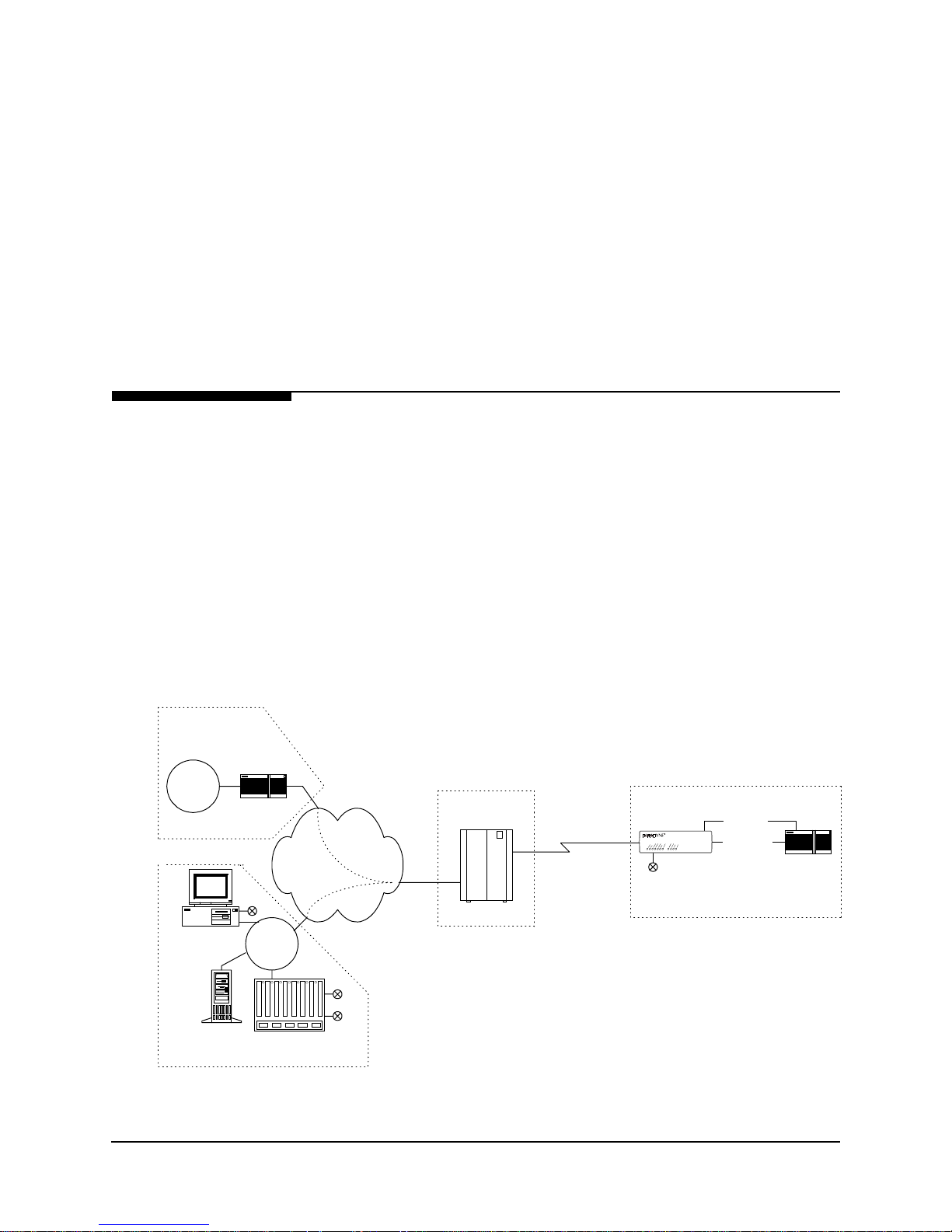
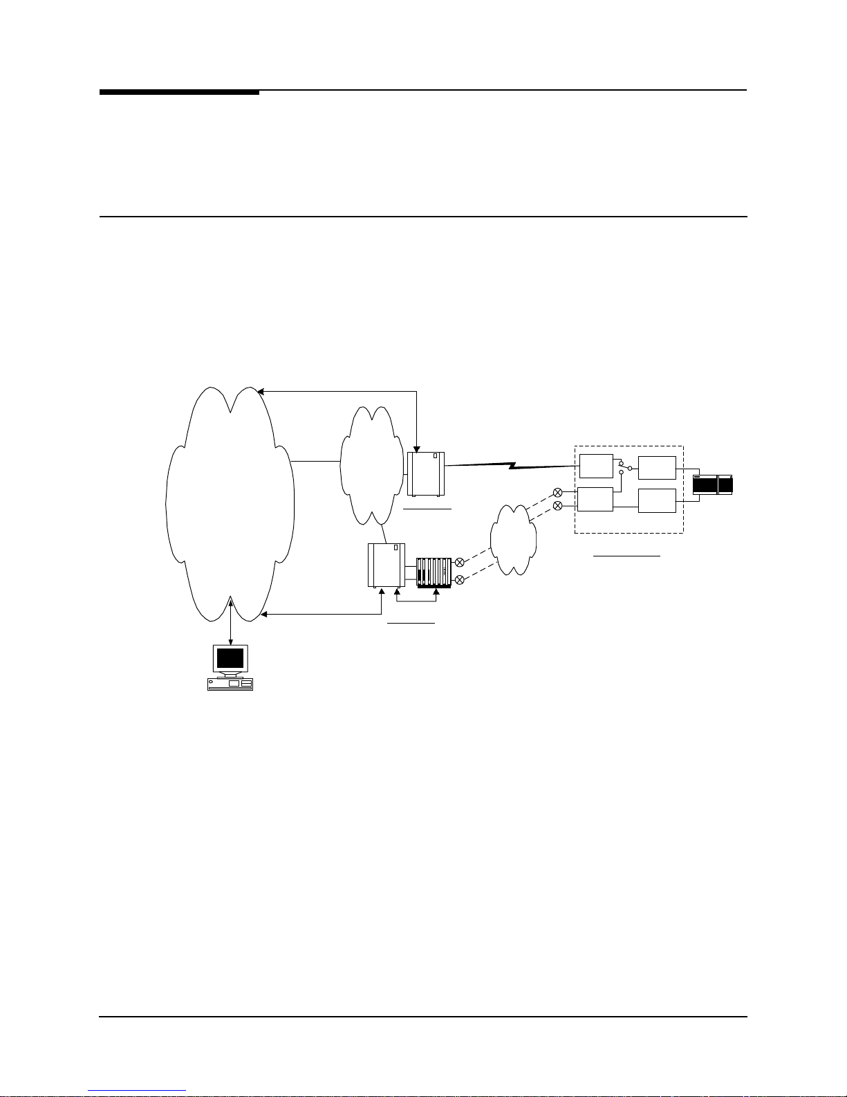
Figure 2-1 shows a system level view of the FrameSaver NP 110, including
management t ransport. As shown in the figure, the Fr ame Relay network provides
Permanent Virtual Circuits (PVCs) for both the Customer Data and FrameSaver NP
110 management.
NOTE: FrameSaver NP 110 is transparent to SVCs (Switched Virtual Circuits).
The NP 110 can have up to two I P Address es for ma nagement. On e IP Addres s allows
it to communicate with SNMP work stations that have access to the NSP management
PVC. A second IP Address can provide manag ement ac cess v ia a cu stomer d ata PVC.
FrameSaver NP 110 can also send SNMP Traps to multiple SNMP Stations via the
management PVCs. The integral modem is used to dial into the Network Control Center (NCC) Terminal Ser ver to report faults that are prevented fr om being repor ted over
the PVC management channels. It can also accept maintenance calls from NCC Work
Stations to support operator interaction, and accept inbound calls from a customer or
NCC Work Station to manage co-located devices such as routers.
End User Premise
FrameSaver
NP 110
FrameSaver NP 110
Dial Line
Serial Port
(Cust. PVC)
Console Port
Frame Relay
NCC
LAN
Backbone
Cust.
PVCs
Mgmt
PVC
IP Ov e r
Frame
POP
Frame Sw itch
Customer &
Mgmt PVCs
Router
SNMP Alarm
Server
Network Control Center
Terminal Server
Figure 2-1 FrameSaver NP 110 Typical Network Application
980-001-0240B FrameSaver NP 110 User’s Manual - Installation Guide 2-1
November 2000
2 Description
FrameSaver NP 110 provides a configuration option to capture an d rank IP Traffic in
either Top Conversation Pair or Top Talker/Listener mode. By examining Top IP Traffic statistics, the network manager can determine the local device or the host/client
connections sending and receiving excessive traffic.
DSX/Drop
Adapter Option
The FrameSaver NP 110 can be factory-optioned to include an integral DSX/Drop
Adapter module (Drop & Insert). The DSX/Drop adap ter inclu des a DSX Port an d an
additional V.35 Drop Port which are used to support Integrated Voice/Data (IVD) access applications.
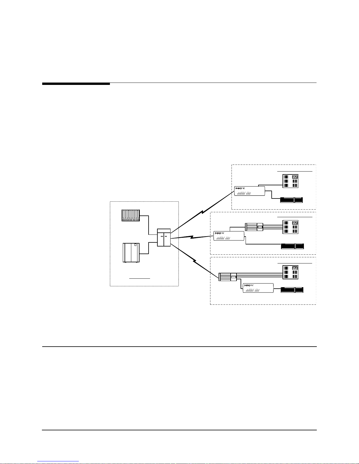
Figure 2-2 shows three IVD applications. In each case, the IVD traffic is carried to a
NSP POP where a DCS is employed to groom the voice and data traffic to the appropriate switching device.
Configuration (a)
DS1
FrameSaver NP 110
PBX
Router
Configuration (b)
FXS
PBX
Router
Configuration (c)
PBX
Voice Switch
Frame Sw itch
NSP POP
DCS
T1
T1
T1
FrameSaver NP 110
FrameS aver
NP 110
Channel Bank
FrameS aver
NP 110
Channel Bank
FXS
FrameSaver NP 110
Figure 2-2 Typical Integrated Voice and Data Applications
DSX Port
2-2 FrameSaver NP 110 User’s Manual - Installation Guide 980-001-0240B
In configuration (a) in Figu re 2-2, voice tr affic is delive red toward the ne twork from a
PBX through a DSX (DS1 compatible) connection. In this case, the FrameSaver NP
110 terminates the T1 facility and provides a “drop” function which separates the T1
into voice and data channels.
FrameS aver
NP 110/120
November
Router
2000
2 Description
Channel Bank
Behind Channel
Bank
Second V.35
Drop Port
In configuration (b), vo ice traffic is delivered t oward the network f rom a PBX through
individual FXS circuits. In this case, the FrameSaver NP 110 terminates the T1 facility
and provides a “drop” function that separates the DS 1 into a voice bu ndle. The bundl e
is then delivered to a channel bank for conversion into m ultiple FXS circuits and a single V.35 frame relay User Interface data circuit for the router. This configuration facilitates inband access to the T1 performance through simple inband transport.
In configuration (c), voice traffic is delivered toward the network from a PBX through
individual FXS circuits. In this case, a channel bank terminates the T1 facility and provides a “drop” function that separates the DS1 into multiple FXS circuits and a single
frame relay User Interface data circuit. These circuits can be delivered to a standard
FrameSaver NP 120 as V.35 or to a standard FrameSaver NP 110 as a DS1.
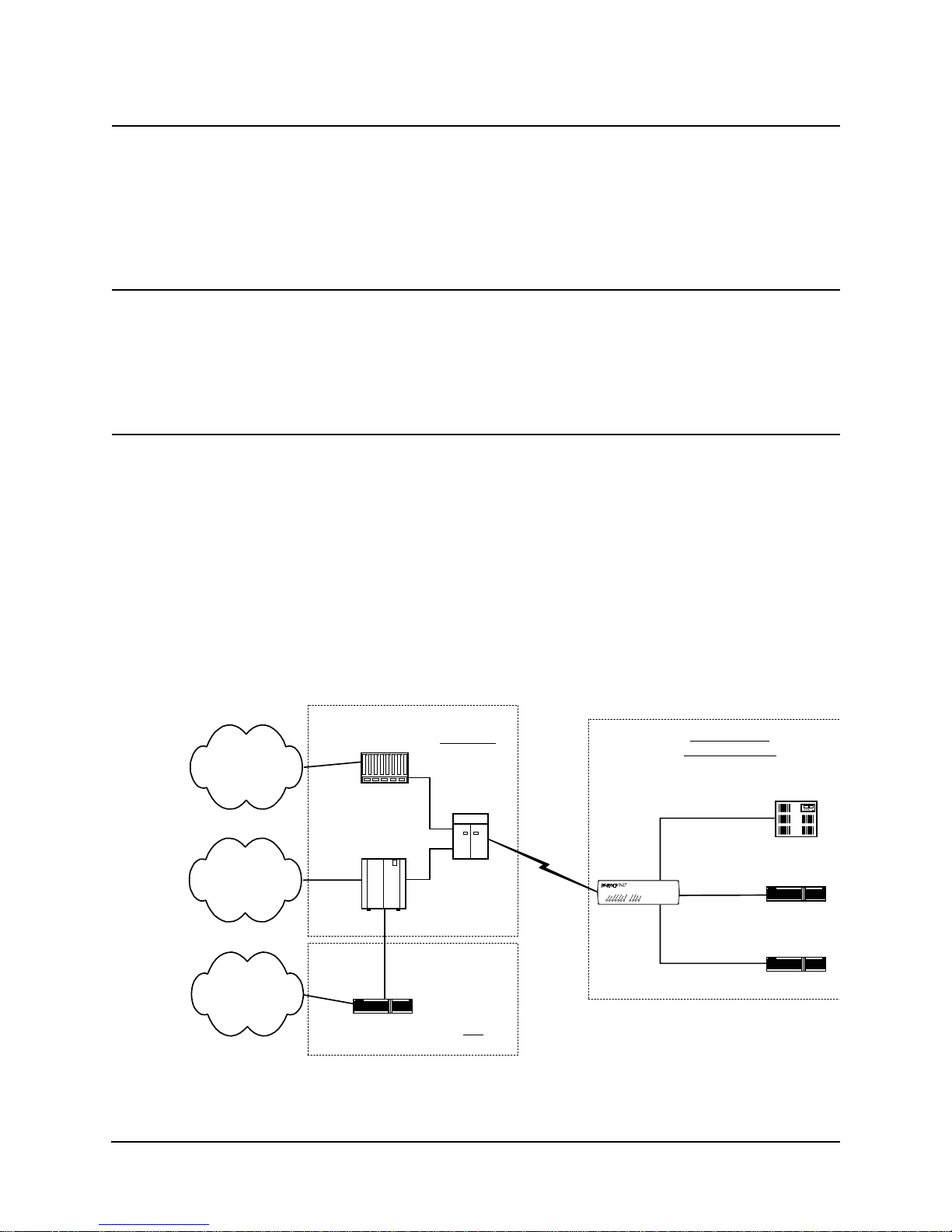
Figure 2-3 shows an application in which a third bundle of DS0s are integrated into the
T1 stream and delivered to a separate V.35 drop port. In this applicati on, one group of
DS0s are assigned to the customers PBX via the DSX port and used for direct access
to the IXC’s inter-LATA dial network. The second group of DS0s are channeled via
our V.35 User (frame aware) port for use on the customer’s frame relay Virtual Private
Network. Then for security and bandwidth allocation purposes, the third group of
DS0s for Internet access are channelized to a different router via a V.35 Drop port.
Depending on the network architecture, the ISP could be co-located with the IXC DCS
or be remote from it, and the traffic on this bundle may or may not be frame relay.
Switch Voice
Cloud
PVN
Frame Relay
Cloud
Inte rne t
This configuration could exist with configuration a, b, or c described on the previous
page.
Customer Site
Configuration (a)
DSO Bundle 1 - Voice
FrameSaver NP 110
User
Port
DSO Bundle 3 - Frame
DSX-1
DSO Bundle 2
Frame
V.35
V.35
PBX
Router A
Router B
Voice Switch
Frame Sw itch
Bundle 2
Frame
Gateway Router
NSP POP
Bundle 1 - Voice
Bundle 2 and 3 -Frame
Bundle 3 - Frame
DCS
ISP
T1
FrameS aver
NP 110
DSX Port
Drop Port
Figure 2-3 Integrated Voice and Dual Data Application
980-001-0240B FrameSaver NP 110 User’s Manual - Installation Guide 2-3
November 2000
2 Description
ISDN Adapter
Option
ISDN Backup
IP Ma n agement
Network
The FrameSaver NP 110 can also be factory-optioned to include an integral ISDN
Adapter module.
The ISDN adapter includes four “U” ISDN TA Interfaces with two integral NT1 Inverse Multiplexers, thereby providing up to 512 Kbps of switched connectivity for network Backup and/or additional Bandwidth On-Demand.
Backup in Frame Relay Protocol utilizing the Router’s Primary Port can be via dedi-
cated PVCs on an alternate port, or the frame switch manag er may reroute the or iginal
PVCs to the Backup Frame Switch. It is also possible to b ypass the entire Frame Relay
Network and initiate backup to a pool of ports on an alternate Frame Switch connected
directly to another Router.
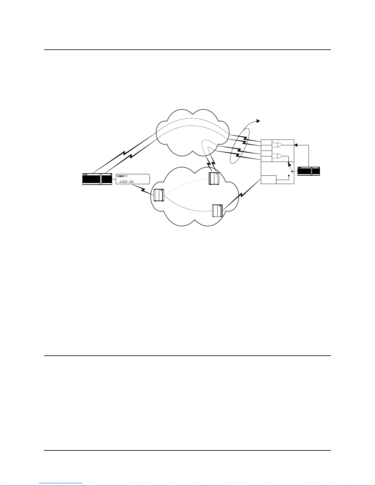
A typical network configuration showing the backup connection to a Backup Frame
Switch using rerouted PVCs is shown in Figure 2-4.
F/S Control
NP 11 0 D ata
& Control
F/S & IMux Control
Control
Frame
Backbone
Backup
Frame
Switch
Frame
Switch
Primary Node
Inv e r s e
Mu lt i plexer
Control
Backup Node
NP 11 0 D ata
PRI 1
PRI 4
& Control
IS DN
BRI 1
BRI 4
CSU
IS DN
FrameSaver
NP 110
Customer Location
V.35
Data
On
Demand
Router
Work Station
Figure 2-4 Typical Backup Configuration
The backup process is described as follows:
2-4 FrameSaver NP 110 User’s Manual - Installation Guide 980-001-0240B
•
FrameSaver NP 110 detects loss of connectivity at CSU.
•
ISDN Adapter card calls Backup Frame Switch and is identified by caller ID.
•
Frame Switch Manager either reroutes original PVCs, or Frame Switch uses
alternate PVCs for the backup connection.
•
FrameSaver NP 110 switches the data path when connected.
•
Associated routers determine that PVCs have been established through LMI
enquiries.
•
Communication is resumed.
November
2000
2 Description
ISDN Bandwidth
On-Demand
Router
Bandwidth On-Demand provides an additional network connection for a second DTE
(router) port based on a r equest fr om th e DTE. In this configurat ion t he NP 110 ISD N
Adapter is protocol-transparent. The Router determines the protocol used.
A typical network configuration showing simultaneous Bandwidth On-Demand and
Backup connections is shown in Figure 2-5.
Bonding
Mode 1 or MLPPP
FrameSaver
NP 110
FrameSaver NP 110
Switch
ISDN Cloud
Backup Switch
Frame Relay Cloud
Primary Switch
TA
TA
TA
TA
CSU
FrameS aver
NP 110
Bandwidth
On Demand
Router
Figure 2-5 Typical Simultaneous Bandwidth On-Demand Configuration
ISDN Adapter
ML-PPP Support
The bandwidth on-demand process is described as follows:
•
User’s router detects need for bandwidth and raises DTR on its second port.
•
FrameSaver NP 110 ISDN Adapter calls predetermined number.
•
The Central Router answers the call and establishes communications with the
remote Router.
•
Communication commences between Routers.
•
User’s Router lowers DTR to terminate the ISDN connection when the
“demand” has been satisfied.
Because the FrameSaver NP equipment is intended to operate as a demarcation device,
it cannot be dependent on co-located equipment to establish a connection. For this reason, connection-associated parameters reside in the FrameSaver NP. ML-PPP operation is based on the use of CHAP or PAP ID or Caller ID to associate each incoming
call with the proper ML-PPP bundle. Because the associated router is using a single
physical port, it must be configured for PPP. The ML-PPP engine supports the Link
Configuration Protocol (LCP) required by PPP. In this case, the configuration values
are defined by the ML-PPP RFC, but are communicated to the router to ensure orderly
operation.
ML-PPP is supported on a dial-out basis on the BOD port only.
980-001-0240B FrameSaver NP 110 User’s Manual - Installation Guide 2-5
November 2000

2 Description
FrameSaver
NP 110
The basic FrameSaver NP 110 includes a T1 interface, network-compliant Fractional
Rate to Full Rate CSU/DSU, a Frame Relay switch function, a Frame Relay manag e ment module, and an SNMP Agent.
The unit includes an internal V.90 modem and two Auxiliary ports. An integral call
director connects the modem to the CSU, AUX 1 port, AUX 2 port, or Option module
(ISDN) based on a DTMF code sent by the caller. All the devices can access the modem for call-out purposes on a first-come, first-served basis.
The unit also includes a CPE power-control feature, whereby power to the CPE can be
momentarily interrupted by operator command to the FrameSaver NP (thereby forcing
a reset of the CPE.)
System software can be downloaded to the FrameSaver NP 110 for upgrades.
Detailed descriptions of the FrameSav er NP 110 indi cators and controls are provided
in
section 5, “Diagnostics” in this manual. Connector and pinout details are provided in
section 3, “Installation” in this manual.
2-6 FrameSaver NP 110 User’s Manual - Installation Guide 980-001-0240B
November
2000
2 Description
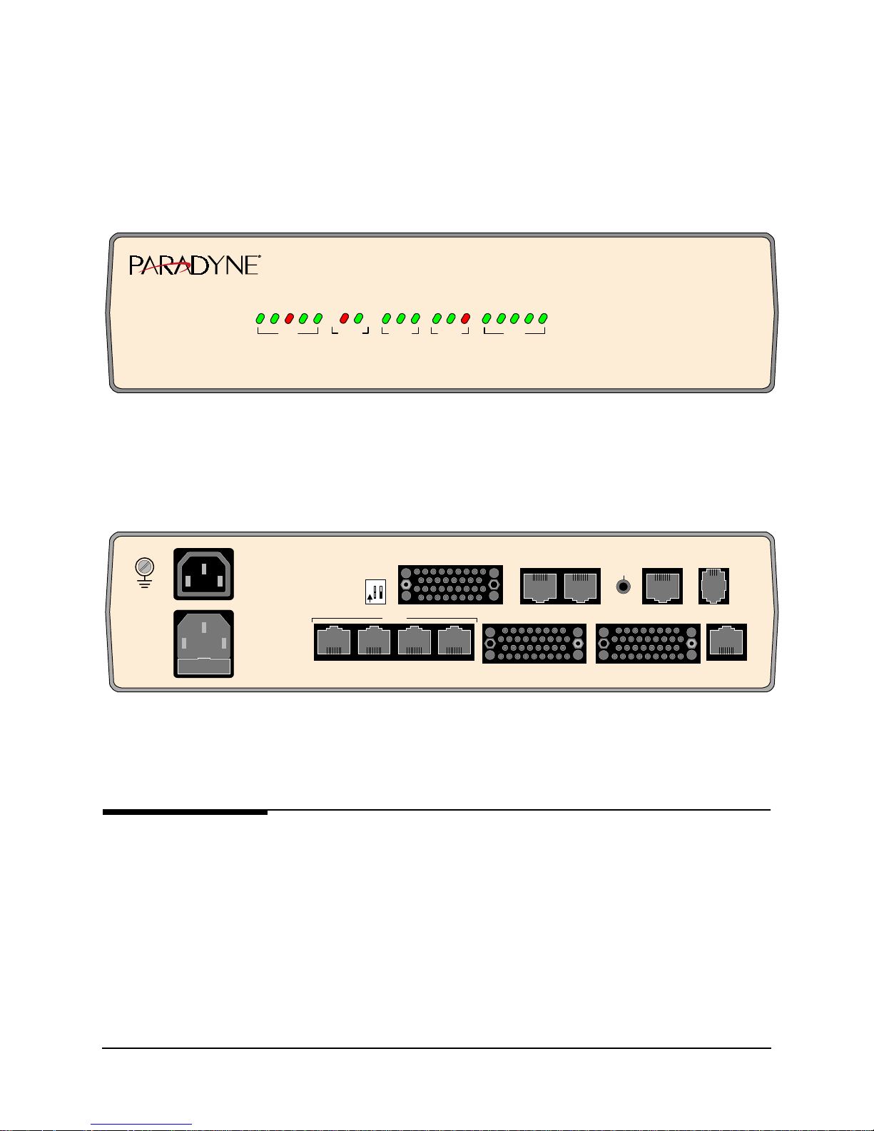
The front and rear panels of the a FrameSaver NP 110 with DSX/Drop and ISDN
Adapter options are shown in Figure 2-6 and Figure 2-7.
E
S
U
T
M
IN
G
R
Y
E
D
W
A
E
O
P
R
UNIT
M
M
E
R
M
T
D
M
S
O
LA
A
M
FR
TE
NETW
I
I
xD
LM
LM
USER
.35 R
R
TxD
V
DROP
M
R
LA
xD
V
.35 TxD
Y
A
D
E
X
A
S
E
D
R
LIN
4
1
3
2
E
E
E
IN
IN
LIN
L
L
ISDN
Figure 2-6 FrameSaver NP 1 10 Front Panel (shown with DSX/Drop and ISDN options)
FrameS averTM NP 110
USER PORT
AUX 1 AUX 2
NETWORK MO DEM
NVM
RESET
DSX PORTISDN DATA PORT DROP PORT
100-240 VAC
5A
50-60 Hz
FUSE
5A/250V
SLOW BLOW
5x20mm
SWITCHED
AC OUT
250VAC
4.5A MAX
"CAUTION"
FOR CONTINUED
PROTECTION
AGAINST RISK
OF FIRE,
REPLACE ONLY
WITH SAME TYPE
AND RATING
OF FUSE.
1 2
12
O
N
LINE 1 LINE 4LINE 3LINE 2
ISD N
Figure 2-7 FrameSaver NP 110 Rear Panel (shown with DSX/Drop and ISDN options)
CPE
Power Control
980-001-0240B FrameSaver NP 110 User’s Manual - Installation Guide 2-7
November 2000
A switched power output conn ector on t he rear o f t he FrameS aver NP 11 0 pr ovi d es a
mechanism for rebooting an external device (us ually the CPE connected to the unit) by
momentarily interrupting its AC power source.
The integral switched outlet responds to an operator command issued to the FrameSaver NP 110 to interrupt power to the connected device for a duration of one (1) to 30
seconds. When commanded, both the Hot and Neutral power leads are interrupted.

2 Description
Operating
Features
Management
Access
This section contains operation information about the following:
•
Management Access
•
Software Download
•
Trap Reporting
•
Modem & Call Director
Management access for control sessions or to retrieve alarm status is provided to the
FrameSaver NP 110 via in-band Telnet, dial-in VT-100 console connection or directconnected VT-100 terminal. FrameSaver NP 110 also supports SNMP “Get,” “Get
Next,” and “Set” commands for retrieval of configurations, trap events, and statistics
information.
Password Security
System Screen
Displays
Security is provided through five levels of password-protected access.
Level 1, System Access Password:
Allows access to system login via User Access Passwords.
Levels 2 - 5, User Access Passwords:
View - Allows user to display all screens.
Test - Allows user to perform diagnostic tests from Status / Test screens and
allows View password access.
Configuration - Allows user to change operating parameters and allows Test
password access.
Supervisor - Grants unlimited access including the viewing and changing of
passwords.
Once successfully logged in, the system provides screen displays for configuration,
testing, and performance statistics. Help text describing each screen’s display fields
and commands is also provided.
2-8 FrameSaver NP 110 User’s Manual - Installation Guide 980-001-0240B
November
2000

2 Description
WAN DLCI
Management
IP Addressing
Customer Data
Center
Customer
LAN
Router
NCC Telnet
Work Station
FrameSaver
NP 110
NCC
LAN
The in-band Frame Relay Management Cha nnel WAN address is defined by the DLCI
(Data Link Connection Identifier). The WAN DLCI can be configured for a Dedicated
PVC, or as a Tunneled channel within a Payload PVC. During initial installation the
WAN DLCI can be set via the unit’s Local Console Port or Dial-In Console Port.
Thereafter the DLCI can also be changed via in-band management access.
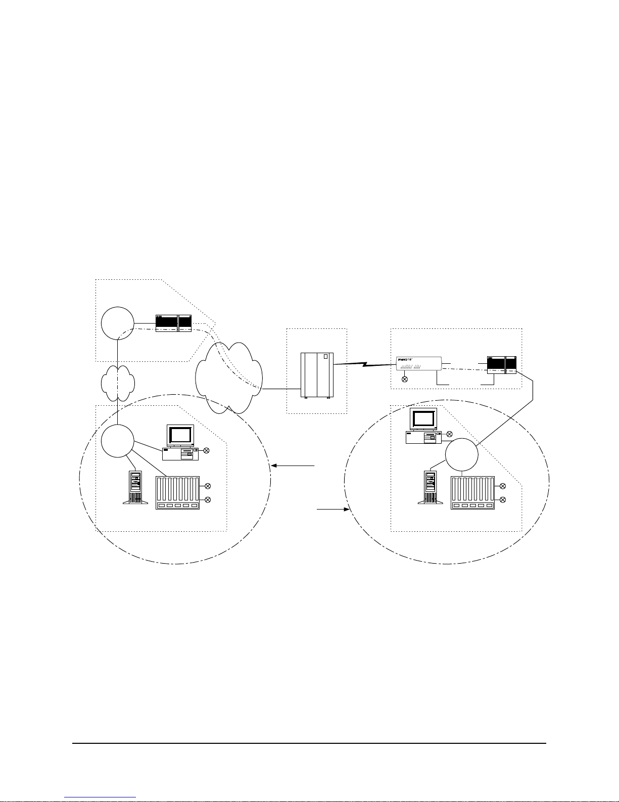
FrameSaver NP 110 has special features for Network Service Providers (NSPs) who
require management access (to the unit) to be isolated from the payload data. This iso lated access is provided either by FrameSaver NP 110’s dedicat ed netw ork -facing
management PVC as shown in Figure 2-1 or by the Tunneled management channel on
a network-facing Payload PVC as shown in Figure 2-8.
HUB
Group
Mgmt
PVC
Cust.
PVCs
Frame Relay
Backbone
IP Over
Frame
POP
FrameSaver NP
Customer &
Mgmt PVCs
Frame Sw itch
End Us er Prem ise
Serial Po rt
(Cus t . PVC)
FrameSaver NP 110
Console Port
Dial Line
Router
SNMP Alarm
Server
Terminal Server
Network Control Center
Tunnel management is accomplished by a FrameSaver NP HUB (FrameSaver NP100
class unit) located at a site which supports up to 48 PVCs connected to FrameSaver NP
units located at remote (spoke) sites. The HUB unit perfo rms the r outing and encap sulation function for manag ement channel mes sages going to and from the rem ote units.
The HUB is connected to the network management systems by a separate dedicated
group management PVC.
980-001-0240B FrameSaver NP 110 User’s Manual - Installation Guide 2-9
November 2000
Figure 2-8 Tunneled Management
2 Description
Customer Data
Center
Customer
LAN
Mgmt
Router
FrameSaver NP 110 also provides expanded management access to the unit through
the following features:
•
Support for two IP Addresses.
•
An optional network-facing management channel via a specified IP Address
on a specified payload PVC.
•
An optional CPE-facing dedicated PVC management channel.
These optional management paths are shown in Figure 2-9.
End User Premise
FrameSaver
NP 110
FrameSaver NP 11 0
Dial Line
Serial Port
(Cu s t. P V C)
Console Port
Router
Cust.
PVCs
Frame R elay
Backbone
IP O v e r
Frame
POP
Customer &
Mgmt PVCs
Frame Sw itch
NCC
LAN
NCC Telnet
W ork S tat io n
SNMP Alarm
Server
Terminal Server
Network Control Center
NCC Telnet
Payloa d
W ork S tat io n
OR
CPE
SNMP Alarm
Server
Network Control Center
Figure 2-9 Payload / CPE Management
NCC
LAN
Terminal Server
Mgmt
2-10 FrameSaver NP 110 User’s Manual - Installation Guide 980-001-0240B
November
2000

2 Description
With these features, NSP and/or customer management of the unit can be accomplished through three basic management modes:
•
The primary IP Address is associated with the network-facing dedicated PVC
or Tunneled payload PVC. In this mode, there may be a secondary IP Address.
The secondary IP Address can be associated with a specified payload PVC or a
dedicated CPE-facing PVC.
•
The primary IP Address is associated with a specified payload PVC. There is
no secondary IP Address.
•
The Primary IP Address is associated with a dedicated CPE-facing PVC. There
is no secondary IP Address.
980-001-0240B FrameSaver NP 110 User’s Manual - Installation Guide 2-11
November 2000

2 Description
WAN Management
IP Address
FrameSaver NP 110 utilizes one IP Address on the dedicated, network-facing Wide
Area Network (WAN) management channel. This address is embedded within the various communications protocol stacks used for SNMP, Telnet and PPP. The unit’s WAN
Management IP Address may be automatically learned from the first message received
on the management PVC, or it can be set via the local or remote Console Port.
When optioned with ISDN, FrameSaver NP 110 can have several communications
paths that allow the management channel to connect to the frame relay network in different places. Each of these connection points could result in the management PVC
routing through different IP sub-nets to reach the Network Contro l Center, or it may be
desirable to have the FrameSaver NP 110 appear as a logically different object in the
SNMP manager, especially if static routing and dedicated backup ports are utilized.
The setting/learning of these additional IP Addresses is described in detail in Section
4, “Configuration,” in this manual.
FrameSaver NP 110 will retain in Non-Volatile Memory (NVM), a separate WAN IP
Address for each connection point. All communications via OOB PPP (Out-Of-Band
Point-to-Point Protocol ) will utilize whatever IP Address is in effect depending on how
the unit is currently connected to the network. There are several options for establishing the WAN IP Address within the FrameSaver NP 110.
When the unit is shipped from the factory or when NVM is cleared on initial installation, the WAN IP Address for each connection point is set to 000.000.000.000 , wh ich
indicates no address is known.
Software
Download
The WAN IP Address to be used on the T1 link is automatically “learned” from the
first valid IP message received over the unit’s management PVC. Learning will take
place as long as the value of the WAN IP Address in NVM is 000.000.000.000. Once
the IP Address is set or learned it is retained and used until the NVM is cleared or another addre s s is manually set.
The FrameSaver NP 110 system software (firmware) is stored in flash memory. A new
version of the softwa re can be down loaded to the uni t for sof tware upg rade, or fo r restoration in the event an error is detected in the flash storage.
A description of the software download process is provided in Section 5, “Diagnos-
tics,” in this manual.
2-12 FrameSaver NP 110 User’s Manual - Installation Guide 980-001-0240B
November
2000

2 Description
Trap Reporting
Event Log
The FrameSaver NP 1 10 provides a MIB which includes s t andar d MIB -II gro ups an d
also contains a Private MIB Extension which supports the issuance of unique Traps.
Traps are notifications of events which are significant in terms of performance and/or
troubleshooting.
Traps are issued either in-band or dial-out (out- of-band) via the on-board modem, depending on the specific fault detected.
The MIB objects and the Trap reporting path for each are listed in Section 5, “Diag-
nostics” of this manual.
FrameSaver NP 110 includes an Even t Log which captures and Trap occurrences and
logs them into a table for SNMP retrieval. The table stores up to 255 of the latest occurred events.
The log table includes the following:
•
A unique event number for each event. Maximum number is 65,536 after
which the count restarts. The count is als o restar ted b y a un it res et or power up.
•
A relative time-stamp which counts from when the unit last started operation.
•
A description of the event, including any data included in the Trap regarding
that event.
980-001-0240B FrameSaver NP 110 User’s Manual - Installation Guide 2-13
November 2000
 Loading...