

Page 1

FrameSaver® DSL 9788 Router
Installat i on Inst r uct ions
Document Number 9788-A2-GN11-00
July 2002
Contents
F rameSaver DSL Router Overview ............................................................... 2
Upgrading a Unit to Advanced SLM Feature Set .......................................... 3
Product Documentation Online ..................................................................... 3
Package Checklist ......................................................................................... 4
Wiring and Cables You May Need ................................................................ 5
Provisioning Data Circuits Before Installation ............................................... 6
Installing the Router ...................................................................................... 7
Power-On ...................................................................................................... 11
Status LEDs .................................................................................................. 12
Troubleshooting ............................................................................................. 13
Configuration Setup ...................................................................................... 14
Verifying that Self-Test Passed ..................................................................... 17
Using the Easy Install Feature ...................................................................... 17
Completing Setup From the NOC ................................................................. 18
Setting Up for In-Band Managemen t ............................................................ 19
Provisioning the Router Interface .................................................................. 22
Cables and Connectors ................................................................................ 22
Router Technical Specifications .................................................................... 25
Impor tant Safety Instructions ........................................................................ 26
Government Requirements ........................................................................... 27
Warranty, Sales, Service, and Traini ng Information ...................................... 28
1
Page 2
FrameSaver DSL Router Overview
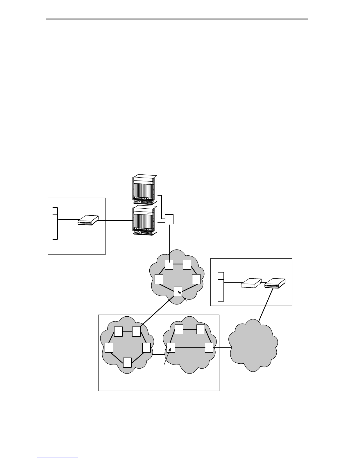
The FrameSaver® DSL (Digital Subscriber Line) Router is a component in the
FrameSav er system. This system allows you to perform end-to-end service le vel
management (SLM) across a hybrid DSL/ATM/Frame Relay network. Service providers
can isolate and correct problems remotely from their NOC (Netw ork Operations Ce nter).
The router has a DSL inter face and is a manageable frame re lay-aware endpoint . It
operates as a bridge or an IP router that conne cts a DSL link to an Ethernet network.
The FrameSaver DSL Router is used for data only and provides corporate LAN access
over traditional twisted-pair copper telephone wiring. Copper pairs run from the central
office (CO ) to the customer premises ( CP ) to cr eate the local loop. The local loop
terminates on the customer premises at the demarcation point in a punchdown block or
network interface device (NID). The following diagram shows a typical use of the
FrameSav er DSL Router in a network.
Central Office
Customer
Premises–
Remote Site
LAN
FrameSaver
DSL 9783
Bridge/Router
Endpoint
DSL
Copper
Loop
GranDSLAMs
Access
Network
ATM
Switches
P
O
W
E
R
E
N
T
R
Y
M
O
D
U
L
E
L
C
E
F
L
T
O
U
N
I
T
:
L
I
N
E
A
P
O
W
E
R
E
N
T
R
Y
M
O
D
U
L
E
R
I
G
H
T
U
N
I
T
:
L
I
N
E
A
B
48V RTN
L
E
F
T
U
N
I
T
:
L
I
N
E
A
R
I
G
H
T
U
N
I
T
48V NEG
:
L
I
N
E
B
48V RTN
48V NEG
W
A
R
N
I
N
G
!
P
O
W
E
R
M
U
S
T
B
E
D
I
S
C
O
N
N
E
C
T
E
D
A
T
B
T
E
H
F
O
E
R
S
E
O
U
R
R
E
M
C
E
O
V
I
N
G
O
R
I
W
N
S
A
T
R
A
N
L
I
N
L
I
G
N
!
G
P
T
O
H
W
I
S
E
R
P
W
M
R
U
S
E
T
N
T
B
R
E
Y
D
M
I
S
O
C
D
O
U
N
L
N
E
E
C
T
E
D
A
T
B
T
E
H
F
O
E
R
S
E
O
U
R
R
E
M
C
E
O
V
I
N
G
O
R
I
N
S
T
A
L
L
I
N
G
T
H
I
S
P
W
R
E
N
T
R
Y
M
O
D
U
L
E
B
C
L
O
P
O
W
E
R
E
N
T
R
Y
M
O
D
U
L
E
L
C
E
F
L
T
O
U
N
I
T
:
L
I
N
E
A
P
O
W
E
R
E
N
T
R
Y
M
O
D
U
L
E
R
I
G
H
T
U
N
I
T
:
L
I
N
E
A
B
48V RTN
L
E
F
T
U
N
I
T
:
L
I
N
E
A
R
I
G
H
T
U
N
I
T
48V NEG
:
L
I
N
E
B
48V RTN
48V NEG
W
A
R
N
I
N
G
!
P
O
W
E
R
M
U
S
T
B
E
D
I
S
C
O
N
N
E
C
T
E
D
A
T
B
T
E
H
F
O
E
R
S
E
O
U
R
R
E
M
C
E
O
V
I
N
G
O
R
I
W
N
A
S
T
R
A
N
L
I
N
L
G
I
N
!
G
P
T
O
H
W
I
S
E
R
P
W
M
R
U
S
E
T
N
B
T
R
E
Y
D
M
I
S
O
C
D
O
U
N
L
N
E
E
C
T
E
D
A
T
B
T
E
H
F
E
O
R
S
E
O
U
R
R
E
C
M
E
O
V
I
N
G
O
R
I
N
S
T
A
L
L
I
N
G
T
H
I
S
P
W
R
E
N
T
R
Y
M
O
D
U
L
E
B
C
L
O
Hotwire
DSL
ATM
NNI(s)
P
O
W
E
R
A
L
A
R
M
S
A
B
F
a
n
M
a
j
o
r
M
i
n
C
K
S
E
R
I
A
L
A
C
M
C
C
A
L
A
R
M
L
A
N
2
/
W
A
N
S
L
4
O
T
6
8
A
1
0
1
2
1
4
S
E
R
I
A
L
A
L
A
R
M
1
3
C
K
S
M
5
C
M
7
9
B
1
1
1
3
P
O
W
E
R
A
L
A
R
M
S
A
B
F
a
n
M
a
j
o
r
M
i
n
C
K
S
E
R
I
A
L
A
C
M
C
C
A
L
A
R
M
L
A
N
2
/
W
A
N
S
L
4
O
T
6
8
A
1
0
1
2
1
4
S
E
R
I
A
L
A
L
A
R
M
1
3
C
K
S
M
5
C
M
7
9
B
1
1
1
3
o
r
1
6
1
8
1
5
1
7
o
r
1
6
1
8
1
5
1
7
Services
FR/ATM
IWF
Aggregation
Switch
(Optional)
ATM
ATM
Switches
FR Network
FR
Switches
Customer Premises–
HQ Site
FrameSaver
LAN
Endpoint
Router
TDM
Access
Network
Frame Relay NSP's Network
ATM – Asynchronous Transfer Mode
DSL – Digital Subscriber Line
FR – Frame Relay
HQ – Headquarters
00-16915a
IWF – Interworking Function
LAN – Local Area Network
NSP – Network Service Provider
TDM – Time Division Multiplexer
2
Page 3

The FrameSav er DSL Router is available in two feature sets:
Diagnostic Feature Set pr ovides basic frame relay and diagnostic capa bil ity.
Advanced SLM (Service Lev el Management) Feature Set provides the same
feat ures as the Diagnostic Feature Set, plus service level management and
reporting capabil ity.
Refer to
DSL router’s features, and the capabilities provided by each feature set.
About FrameSaver DSL Devices
in th e U ser’s Guide for a list of FrameSaver
Upgrading a Unit to Advanced SLM Feature Set
A FrameSaver DSL Router with the Diagnostic Feature Set can be upgraded to the
Advanced SLM Feature Set at any time by orderin g a FrameSa ver Advanced SLM
Activ ation Certificate (Fea tur e Number 9788-C1-220). A certificate can be ordered f or a
single DSL router, or for many DSL routers. You must specify the mod el t o be acti vated
(for example , 9788-Rtr), your OpenLane SLM system license key number , and the
number of router activations to be included on the certificate.
®
The OpenL ane
of Advanced SLM features and to manage the certificate activations incl uded in the
certificate.
To learn more about activating the Advanced SLM F eature Set, refer to the
SLV Activation Instructions
representative.
SLM system , Rel ease 5.3 o r l ater, i s requ ired t o sched ule t he acti vat i on
FrameSaver
(Document Number 9000-A2-GK43), or con tact your sales
Product Documentation Online
Complete documentation for this product is available at www.paradyne.com.
Select
Select the following document:
Library → Technical Manuals → FrameSaver Frame Relay Devices.
9700-A2-GB20
FrameSaver DSL, Models 9783 and 9788, User’s Guide
To order a paper copy of a Paradyne do cument:
Within the U.S.A., call 1-800-PARADYNE (1-800-727-2396)
Outside th e U.S.A., call 1-727-530-8623
3
Page 4

Package Checklist
In addition to these instructions, verify that your package contains the following:
❑
FrameSaver DSL Router
❑
Power cord with power transfor mer
❑
Tie wrap for power cord st rain relief
❑
DSL network access cable (with U .S. models only)
❑
FrameSaver DSL Router, Models 9783 and 9788, Quick Reference
Number 9700-A2-GL11)
Be sure to register your war ranty at www.paradyne.com/warranty.
(Document
4
Page 5

Wiring and Cables You May Need
The following wiring and cables are used with this product, which uses standard
interface connectors:
Standard conn ectors: An 8-pin modular (similar to RJ45) wall jack for the DSL
network connection.
DSL wiring: Unshi elded twisted-pair wiring (CAT3, or better). The CAT3 wiring must
meet EIA/TIA-568 specifications with 24 AWG (0.5 mm) or 26 AWG (0.4 mm).
Ethernet wiring: Shielded twisted-pair wiring (CAT5, or better). The CAT5 wiring
must meet EIA/ TIA- 568 specifica ti ons with 24 AW G (0.5 mm) or 26 AWG (0.4 mm) .
For standard cabl es, refer to
numbers. For Paradyn e cables, cont act your sales representative to order them.
Cables and Connectors
Interface
Connection Cables
COM
Communication
port to a PC or
asynchronous
terminal
ETHERNET
Ethernet port to a
NIC on a PC or an
Ethernet hub
NET
Network port to the
DSL wall jack
DB9-to-D B9, st andard EIA-232
straight-through cable —
For connect ion to a PC NIC:
Standard Ethernet crossover cable 9008-F1-550
For connection to an Ethernet Hub:
Standard Ethernet straight-through cable —
Standard straight-through DSL network cable
with 8-pin modular c onnectors, si mil ar to an
RJ45-to-R J45 cable. Su ppli e d with U.S.
models.
on page 22 for standard pin
Feature
Number
3100-F1-500
5
Page 6

Provisioning Data C ircuits Before Installation
Before install ing the rout er, use the OpenLane SLM system’s Provision Circuit screen to
add:
New circu it s that start at the FrameSaver DSL endpoint and tra verse the SCM and
ATM lin e card in the H o twire
The default VC sets (from 1 to 4)
A group of 250 VCs can be allocated to each line card , which can be assigned to any
port on the card. These custom connections carry the frame relay traffic.
Note that before the custom cross-connect ions are configured, the Maximum VCI
number for the uplink VP to be used by these custom connections must be specified on
the Max VCI per VPI screen, and the apply changes executed.
For ATM line cards, custom connections can be used to expand the number of VCs
connected to the c ard. Eac h of the 250 VCs can b e cross- con nected f rom any VC on t he
uplink to any port on the line card.
The fol lowing information is collected by the Provis ion Circuit process :
Uplink VPI/VCI
®
GranDSLAM™
Slot number and Por t number of the DSL connection
Traffic Profile
DSL link VPI/VCI
Frame relay DLCI (provided by NSP)
Frame relay CIR, B
, Bc (provided by NSP)
e
A Circuit ID is then applied to the newly defi ned circui t, and sto red in both the router and
the OpenLane SLM sy stem.
6
Page 7
Installing the Router
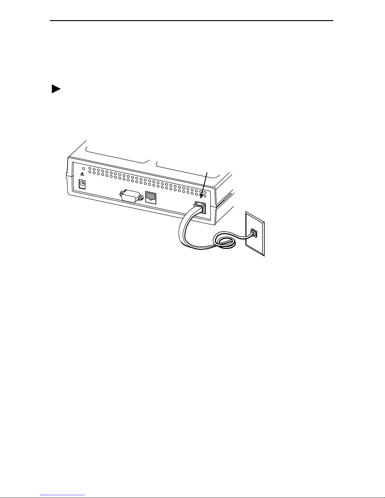
Place the F rameSav er DSL Router on a flat surface, wit h clearance for the rear
connectors.
Procedure
1. Use an 8-pin modular cable (supplied with U.S. models).
Insert one end of the cabl e into the jack label ed NET. Insert the other end int o the
wall jack for DSL data communications.
NET
POW
ER
COM
ETHERNET
NET
DSL
Network
01-16981
7
Page 8
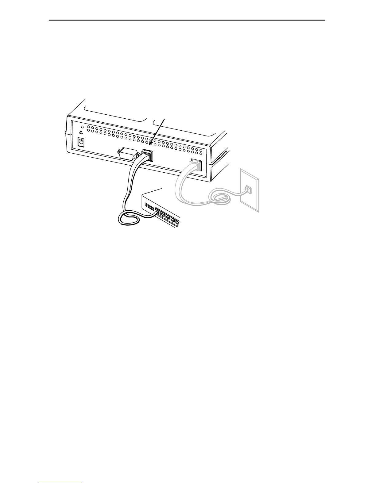
2. Use an 8-pin Ethernet ca b le f o r the E thernet c onnecti on. Insert one end of the cab l e
into the jac k la beled ETHERNET.
— Use a straight-through cable to connect the ot her end of the cable to an
Ethernet hub. Do not connect to the hub’s opti onal Uplink connection with a
straight-through cable; the Uplink connection requires an Ethernet crossover
cable.
ETHERNET
P
OWER
COM
ETHERNET
NET
Ethernet
Straight-Through
Cable
Hub
01-16982
– or –
— Use an Ethernet crossover cable to connect to a PC with an Ethernet Network
Interface Card (NIC) i nstalled or a hub’s Uplink connection.
8
Page 9
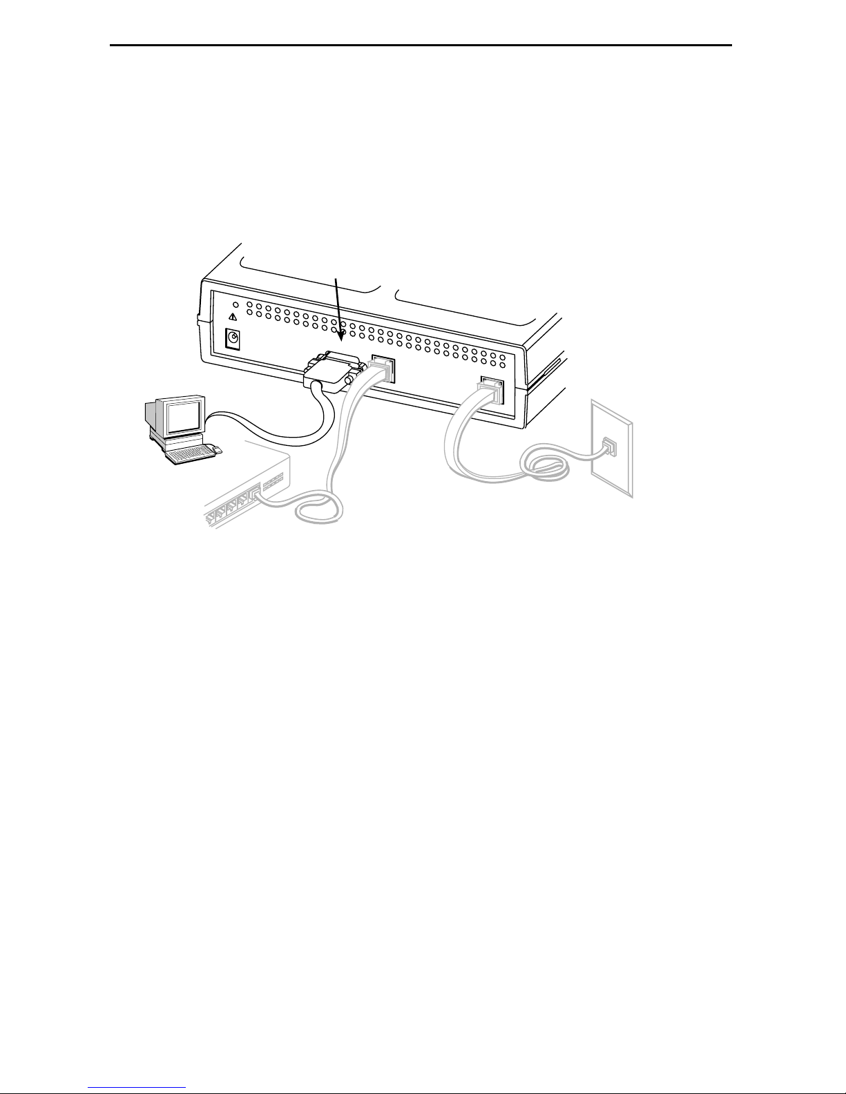
3. Use a VT100-compatible asynchronous terminal or PC to set up management
access to the unit. Insert the DB9 end of an EIA-232 cable into the router’s COM
port. Tighten the scr ews on e ach side of the conne cto r . Insert the other end into the
terminal or PC.
The terminal or PC’s confi gurat ion must be compat ib le wit h the r out er’s. Refer to the
procedure on page 15 of
the COM port, refer to
Connecting an External Modem
Configurati on Setup
. If connecting an external modem to
on page 24.
COM
P
OW
ER
COM
ETHERNET
NET
01-16983
9
Page 10

4. Insert the supplied power cord’s round end into the jack labeled POWER. Plug the
transformer into an AC outlet.
Install the supplied tie wr ap for strain relief, as shown.
Grounded
Power
Outlet
Cable
Tie
POWER
POW
ER
COM
ETHERNET
NET
01-16984
Installation of the hardwar e is now complete. Whe n the power cord is installed, the
router goe s thr ough a power-on self -test.
10
Page 11

Power-On
When power is applied, the router performs self-di agnostics and the PWR LED is on.
The self-diagnostics include a power-on sel f-test where all of the LEDs are on.
Refer to
Status LEDs
Troubleshooting
FrameSaver
SHDSL
on page 12 for information about the LEDs. Refer to
on page 13 for LED indications requiring action.
R
®
DSL
SLV
FrameSaver DSL 9788 Router
System OK – green
Alarm – red
Test – yellow
ATM – green
DSL – green
9788
ROUTER
OK
ALM
TEST
ATM
DSL
NetworkSystem
Ethernet Port – green
OK
Port
01-16985
11
Page 12

Status LEDs
After a successful self-test, the LEDs should appear as indicated in BOLD in the
Condition column below.
LED Condition Status
System LEDs
OK ON The router has power.
ALM ON
OFF
TEST ON
OFF
Network LEDs
ATM ON – Green
OFF
DSL Blinking
ON
OFF
Port LED
OK ON
An alarm condition exists.
No alarms have been detected by the router.
The router is performing the power-on self-test, or a test
initiat ed by the service provider is currently acti ve.
No tests are active.
ATM LED is active and cell delineation is in sync.
ATM mode is active and ther e is loss of cell delineation.
The router is in start-up or is retr aining. The LED blink s
on and off about five times per second.
The DSL link is ready to tr ansm it and receive data.
No DSL link has been established, or the link i s down.
The Ethernet port is transmit ti ng and receiving data.
OFF
Self-diagnostics have not been completed successfully.
12
Page 13

Troubleshooting
LED Symptom Action
All LEDs are on. If the LEDs remain on for more than ten m inutes, the router is
not functional. Unplug the router and reapply power. If the
ALM LED is still on, contact the service provider.
ALM LED only
remains on.
ALM and TEST LEDs
are blinking.
The power-on self-test may have failed. Unplug the router
and reapply po wer. If the alarm LED is still on, contact the
service provider.
Firmware download may be in progress. If firmware
download i s not in progress or the LEDs continue b linking for
more than ten minutes, contact the service provider.
Do not
unplug the uni t, unless instructed to do so by the service
provider.
ATM LED is off while
DSL LED is on.
DSL LED is off. Verify that the DSL cable is securely installed on both ends.
DSL LED continues
blinking after the
power-on sel f-test
has completed.
DSL and ATM LEDs
are on, but no data is
being transmitted.
There is loss of cell delineation (OCD) due to line
impairments . Cont act the service provide r.
Unplug the unit and reapply power. If the problem contin ues,
contact the service provider.
The router is a ttempt ing to estab l ish t he DSL li nk, o r a djust ing
the DSL line rate due to line conditions. If the bli nking
contin ues for more than ten minutes, contact the service
provider.
The DSL link has been established, but there is no data
transmission. Verify the Ethernet connection. If the problem
persist s, contact the service provider.
DSL, ATM, and Port
LEDs are on, but no
data is being
transmitted.
Port LED is off. Verify that the Et hernet cable is securel y installed at both
System OK LED is off. Check that the power cord is securely installed on both ends.
TEST LED is on. A test initiat ed by t he service pr ovid er may be act iv e. W ai t ten
DSL and Ethernet links ha ve been established, b ut th ere is
no data transmission. If the problem continues, contact the
service provider.
ends, and at least one PC is connected and po wered on.
Verify that the correct Ethernet straight-through or crossover
cable is installed. Refer to Step 2 on page 8.
If no LEDs are on, the power supply may be defective. Test
the outlet to v erify power. If the out let has power and the
probl e m persists, contact your service representative.
If other LEDs are on, the OK LED may be b urned out. Unpl ug
the unit and reappl y power, and watch all LEDs as the ro uter
perf orms its power-on self-test. If the OK LED is functioning,
call y our service representative.
minutes. If the LED does not go off, contact the service
provider.
13
Page 14

Configur ation Setup
Once the router is installed, i t can be accessed locall y through the menu-driven user
interface via an asynchr onous terminal or PC connection, or remotely via a Telnet
session, and the router’s interfaces can be provisioned. The following provisioning can
be set up:
Frame relay, ATM, and physical layer provis ioning – Typically set up by the LEC
(Local Exch ange Carrier) or CLEC (Competit ive LEC) using the men u-driven user
interface via an ASCII terminal or PC running a terminal emulation program, or a
Telnet session.
Router provisioning, using the CLI – Typically accessed by the frame relay
service provider providing managed router service, or by the end user .
SLM provisioning – Typically set up by the f rame relay service provider, LEC , or
CLEC.
As soon as the router’s COM port is connected to a terminal or PC, the menu-driven
user interface can be accessed. The terminal or PC’s configuration must be compat ible
with the router’s COM port settings.
14
Page 15

Procedure
To access the menu-driven user interface:
1.
Verify the terminal or PC’s configuration:
— Data Rate is set to 19.2 kbps.
— Charact er Length is set to 8 data bits.
— Parity is set to None.
— Stop Bits is set to 1.
— Flow Co nt ro l is set to No n e.
2.
Press Enter to display the Main Menu.
main 9788-RtrSLV
Device Name: Node A 6/05/2001 00:02
MAIN MENU
Status
Test
Configuration
Control
Easy Install
----------------------------------------------------------------------------Ctrl-a to access these functions, Shift-r to access the Router's CLI. Exit
If the Main Men u does not appear:
Press Enter again
Check the terminal or PC settings
Refer to
Troubleshooting
in the User’s Guide
15
Page 16

Menu Navigation
The router sh ould operate using the default (f actory-set) confi guration opt ions. Refe r to
the following table for help in navigating the menus.
Press t he . . . To . . .
Esc key Go back one screen or menu level. For a visual display of
the menu hiera rchy, see the Quick Ref erence.
Tab key, and
Up ( ↑), Down (↓),
Left (←), Right (→)
Arrow keys
Enter or Return key Complete the menu or opt ion selection.
Spacebar Displa y the next available sett ing when changing a
As an example, follow these steps t o go to the Confi guration Edit/Displa y men u so you
can start setting up the unit.
Move the cursor from one menu it em to the next.
configuration option. All the avail able settin gs for an option
appear at the bottom of t he screen.
Procedure
To load a configuration for editi ng:
1. From the Main Men u, pre ss the Tab k ey t wice , or press t he d own (↓) arrow twice, so
the cursor is on Conf iguration.
2. Press Enter to select Configuration. The Load Configuration From menu appears.
3. Press Enter to select Curr ent Configuration (th e cursor is already on this selection).
The Configuration Edit/Display menu appears.
This sequence of steps would be show n as the menu selecti on sequence:
Main Menu → Configuration
Procedure
To save configuratio n changes:
1. Press Ctrl-a to swit ch to t he function ke ys area at the bottom of the screen.
2. Type s (S
3. Press Enter again to save your changes to the Current Configuration (the cursor is
already on t his selection).
To continue configuri ng the router , press Esc until the Configuration Edit/Display menu
reappears . To return to the Main Menu, press Ctrl-a, type m (M
Enter.
ave) and press Enter. The Sa ve Configuration To menu appears.
ainMenu), and press
16
Page 17

Verifying that Sel f-Test Passe d
To verify that the unit passed its self-t est, go to the System and Test Status scr een.
Main Menu
→
Status → System and Test Status
The result s of t he self-test appear di rectly under the screen title.
If any failure messages appear, reset the unit by disconnecting, then reconnecting the
power cord. The unit will perform the self-tes t agai n. If the fa il ure reappears, call your
service representative for assistance.
Using the Easy Install Feature
An Easy Install screen is provi ded for custom configurations, but you are not requir ed to
use it for normal i nstallation. You can configure the rou ter by maki ng selections from the
Configuration Edit/Display menu.
Procedure
1. Select the Easy Install f eature.
Main Menu
Easy Install Screen Example
→
Easy Install
main/easy_install 9788-RtrSLV
Device Name: Node A 6/5/2001 00:01
EASY INSTALL
Node IP Address: 000.000.000.000 Clear
Node Subnet Mask: 000.000.000.000
TS Access: VPI,VCI 0,35
Create a Dedicated Network Management Link
Ethernet Management Options Screen
Network 1 DSL Line Rate Mode Fixed
Network 1 DSL Line Rate (Kbps) 784
Network 1 FRF.8 Encapsulation Mode Transparent
----------------------------------------------------------------------------Ctrl-a to access these functions, ESC for previous menu MainMenu Exit
ave
S
Clear
2. Enter the Node IP Address and Subnet Mask.
17
Page 18

3. Specify TS Access if a Troubleshooting (TS) DLCI or Virtual Circuit (VC) is being
set up f or remote access by the service provider. The default is 0,35.
4. Select Create a Dedicated Netw ork Managem ent Link to set up for permanent
remote access by the NOC. Enter a DLCI, VPI, and VCI at the resulting prompts.
5. Select the Ethernet Management Options Screen to go directly to the Ethernet
Management Options screen. The in ter face (Status) is already enab led.
— Enter the IP Address (for e xample, 10.101.51 .253) and Subnet Mask (f or
example, 255.255.255.0) for the Ethernet interface.
— Enter the Default Gateway Address (the IP Address that will be used for
packets without a specified route).
— Press the Esc key to return to the Easy I nstall screen.
6. Change Network 1 DSL Line Rate (Kbps), if desired. The default is AutoRate.
7. S
ave the configuration and return to the Configuration Edit/Display menu.
Completing Setup F rom the NOC
Procedure
1. Access the router on the TS Management Link tha t was set up at the remote s it e in
Step 4 of
2. Ping the router fiv e ti m es within five seconds. The rout er aut om atically provisions
the TS Access VC and accept s the destination IP addr ess of the Ping as its
temporary IP address, which is used on the ma nagement VC interface.
3. If necessary, open a Telnet sessio n and co nfigur e any sp eci fic co nfigur ati on opti ons
that require input or changes from default settings. Create all customer VCs,
including internal DLCIs and VPI/VCIs on the DSL interface, and cross-connect the
DLCIs to the VCCs.
Using the Easy Install Feat ure
.
18
Page 19

Configuring SNMP Trap Managers and Traps
Procedure
To enter SNMP managers and configure traps:
1.
Select SNMP Traps.
Main Menu
Configuration
→
Management and Com m unication
→
→
SNMP Traps
2.
Configure the following:
— Enable SNMP Traps.
— Identify the total Number of Trap Managers.
— Specify the IP address for each NMS Trap Manager to whi ch traps will be sent .
— Specify the Ini tial Route Destinat ion for each Trap Manager. The default is
AutoRoute.
— Select or disable trap categories, as neede d.
3.
ave the configuration.
S
Setting Up for In-Band Management
If FRF.8 Encapsulation Mode is set to Translat ional, remote management of the router
can still be accomplished in-band, as indicated in the following procedure.
Befor e you use the following procedure, verify that:
The router’s Ethernet interface has already been assigned an IP address that is in
the same subnet as the management IP address entered in Step 5 on page 18 of
Using the Easy I nstall Feat ure
The router is not configured for bridging only
Refer to
Designations
additional information.
Configuring the FrameSaver DSL Router; CLI Commands, Codes, and
Command Line Summaries and Shortcu ts
, and
in the User’s Guide for
19
Page 20

Procedure
1. Create a DLCI on the router virtual port.
Configuration → Vitual Router Ports → DLCI Records
Assign the DLCI number that will be used for management on Serial port 0
(Rtr-S0 – e.g ., DL C I 90 0 ).
2. Create a management PVC using the DLCI just co nfi gured on Serial port 0
to connect t he managem ent link to the router.
Configuration → Management and Communication → Management PVCs
Using the DLCI 900 example, make the following connection:
— Select Name: Mgmt900
— Intf IP Address: Special, and add the IP address for the Ethernet int erface in
Step 5 on page 18 of
— Intf Subnet Mask: Special, and add the Subnet Mask for the Ethernet interface
in Step 5 on page 18 of
— Set DE: Leav e at the default, Disable.
Using the Easy In stall Feature
Using the Easy Install Feature
.
.
— Primary Link: Select Rtr-S0.
— Primary DLCI: Select 900.
3. Return to the M
4. From the CLI, enable password and show the router’s configuration.
en
show config
A list of the router ’s configuration is shown, most of the configuration already
completed using the default values .
interface serial 0.900
ip unnumbered
frame-relay interface-dlci 900
no bridge-group 1
exit
5. Add the route to the routing table.
config t
ip route 10.101.51.253 255.255.255.255 Serial 0.900
save
exit
ain Menu and press Shift-r to access the router’s CLI.
6. Ping the Ethernet management inter face to verify that the router can be reached.
ping 10.101.51.253
exit
The router is now set up for in-band management.
20
Page 21

Verifying the End-to-End Management Path
After installation of a remote ro uter, run an ATM Ping test fr om the Hotwire GranDSLAM.
Procedure
To Ping the router:
1. From the Hotwire ATM Line Card’s Main Menu, sel ect the ATM Ping test.
Diagnostics → ATM Ping
2. Enter a VPI of 0 and a VCI of 35.
3. Select a Direction of Endpoint, then Start.
4. If the test is successful, select a Direction of Network, then Start.
If both tests are successful, t he VC has been tested from end to end.
(D-C)
Checking That Data is Being Received
Procedure
To verify that data is being receiv ed:
1. From the router’s Main Menu, select frame relay performance statistics.
Main Menu
2. Repeatedly R
— V eri fy tha t the counts for F ram es Receiv ed and Char ac ters Rece ive d under the
Frame Rela y Link statistics are increasing.
→
Status
efresh th e screen to:
→
Performance Statistics
→
Frame Relay
— Verify that there are no errors under Frame Relay Errors.
If data is not being received or you are receiving errors, check your cable
connecti ons and replace or repair a damaged cable.
3. Return to the Status menu.
21
Page 22

Checking PVC Connections
Check PVC connections to ve rify that all PVCs, includi ng m anagem ent PVCs, are
configu red and active .
Procedure
To veri fy PVCs:
1. Select PVC Connection Status from the Status menu.
The PVC Connection Status screen shows al l PVC connections, the interface
source and DLCI nu mber of the incoming data linked to the interface, and DLCI
number for the outgoing data. You can also see whether the PVC is active.
2. Verify that each PVC is active.
— If active, the router should be passing data.
— If not active, no data traf fi c can be carried by the PVC . If the PVC is configured
correct ly, the circui t may be down.
Provisioning the Router Interface
The FrameSav er DSL Router defaults to bridge mode. Routing without bridging, and
simult aneous routing and bridging, are also option s.
Use the bridge command f rom the router’s CLI to configure t he brid ge and routing
attributes. Also, enter an Ethernet IP address and a DHCP IP address. Refer to the
Quick Reference for a summary of configur ation options , CLI commands, and def ault
settings.
Cables and Connectors
Refer to
Installing the Router
The DSL network interface uses an 8-pin
unkeyed modular plug. Use a standard
twisted-pair cable rated at CAT3 or better.
on page 7 for cable installation information.
8-Pin
Connector
Pin Number Functi o n
1–3 Not used
DSL
Cable
4DSL Ring
5DSL Tip
6–8 Not used
Pin #8
Pin #1
01-16887-01
22
Page 23

The Ethernet interface connector uses an 8-pin, non-keyed modular plug. Use
shielde d twi sted-pair CAT5, or better, cables. See Step 2 on page 8.
— To connect the router to an Ethe rnet hub, use a str aight-through connection.
8-Pin Straight-through Connections
Pin # Function
Ethernet
Cable
1 10/100BaseT TX D+
2 10/100BaseT TX D –
3 10/100BaseT RX D+
8-Pin
Plug
4 & 5 Not used
6 10/100BaseT RX D –
7 & 8 Not used
Pin #8
Pin #1
98-16055a
– or –
— To connect the router to a PC with an Ethernet NIC card, use an Ethernet
crossover cable.
8-Pin Ethernet Crossover Cable
Function Pin # FunctionPin #
10/100BaseT TX D+
10/100BaseT TX D–
1
2
1
10/100BaseT TX D+
2
10/100BaseT TX D–
10/100BaseT RX D+
Not Used
Not Used
10/100BaseT RX D–
Not Used
Not Used
Pin #1/2 = Orange/White
Twisted Pair
3
4
5
6
7
8
Pin #3/6 = Blue/White
3
10/100BaseT RX D+
4
Not Used
5
Not Used
6
10/100BaseT RX D–
7
Not Used
8
Not Used
99-16518
Twisted Pair
23
Page 24

The communicat ion (CO M) port connector use s a 9-posi tion, EIA- 232-C connec tor.
Pin # Signal Direction
1 Data Carrier Detect (DCD) To DTE (Out)
2 Receive Data (RD) To DTE (Out)
3 Transmit Data (TD) From DTE (In)
4 Data Terminal Ready (DTR) From DTE (In)
5 Signal Ground (GND) —
6 Data Set Ready (DSR) To DTE (Out)
7 Not used —
8 Clear To Send (CTS) To DTE (Out)
9 Not used —
Connecting an External Modem
A standard cr ossover cable can be used to connect the COM port to an external
modem. Configure the external modem to be compatible with the FrameSaver unit.
Refer to
crossover cabl e external modem pin assignments and AT commands to configu re the
modem and enable auto-answer .
Connectors , Cables, and Pin Assignments
in the User’s Guide f or standard
24
Page 25

Router Technical Specifi cations
Item Specification
Approvals
FCC Part 15
Safety Ce rtif ic a tion s
Physical Environme nt
Operating temperature
Storage temperature
Relative humidity
Shock and vibr ation
Power Consumption and
Dissipation
Height x Width x Depth 2.1" x 6.2" x 8.7" (5.3 cm x 15.7 cm x 22.1 cm)
Weight 1 .38 lbs (0. 62 kg)
Class A digital device
Refer to equipment’s label for appro vals on product
0°C to 50°C (32°F to 122°F)
–20°C to 70°C (–4°F to 158°F)
5% to 85% (noncondensing)
Withstands normal shipping and handling
4.5 watts, 60 Hz ±3, 0.135 A at 120 VAC ±12
Result: 15.4 Btu per hour
*
COM Port
Standard
Data rates
NET Port
Line Code
Service
Data rates
Ethernet Port
Standard
Data rates
*
Technical Specifications are subject to change without notification.
9-posi tion (DB9) connecto r
EIA-232-E, V.24 (ISO 2110)
9.6, 14.4, 19.2, 28.8, 38.4, 57.6, and 115.2 kbps
8-position modular unkeyed RJ45-style jack
TC PAM
SHDSL (G.991.2)
200–2312 kbps
8-position modular unkeyed RJ45-style jack
ANSI/IEEE Standard 802.3, Ethernet V ersion 2
10/100BaseT (auto-sensing 10/100 Mbps rates)
25
Page 26

!
Importa nt Safety Instr uctions
1. Read and follow all warning notices and instructions marked on the product or
included in the manual.
2. Slots and openings in the cabi net are provided for ventilation. To ensure reliable
operati on of the product and to prot ect it from ov erheating, these slots and
openings must not be bloc ked or covered.
3. Do not allow any thing to rest on the po we r cord an d do not l ocate t he produc t where
persons will walk on the power cord.
4. Do not attempt to servic e this product yourself, as opening or remo ving covers ma y
expose you to dangerous high voltage points or other risks. Refer all servicing to
qualified service personnel.
5. General purpose cables are used with this product for connection to the network.
Special cables, which may be required by the regulatory inspection authority for the
installation site, are the responsibility of the custom er. Use a UL Listed, CSA
certified, minimum No. 24 AWG line cord for connection to the Digi tal Subscriber
Line (DSL) network.
6. When installed in the final configuration, the product must comply with the
applica ble Safet y Standards and regulatory requirements of the country in which it
is install ed. If necessary, consult with the appropriate regulatory agencies and
inspection authoritie s to ensure compliance.
7. A rare phenomenon can create a v oltage potential between the earth grounds of
two or more buildings. If products inst alled in separate building s are
interconnected, the vol tage potenti al may cau se a hazardous condition. Consult a
qualified electrical cons ult ant to determine whether or not thi s phenom enon exists
and, if necessary, implement corrective action prior to interc onnecting the produ cts.
8. Input power to this product must be pro vided by one of the following : (1) a UL
Listed/CSA certifi ed power source with a Class 2 or Lim it ed Power Source (LPS)
output for use in North America, or (2) a certified transformer, with a Safety Extra
Low Voltage (SELV) output having a maximum 240 VA available, for use in the
country of installation.
9. In addition, if the equi pment is to be used with telecommu nic ations circuit s , tak e the
fol lowing precautions:
— Never install te lephone wiring during a lightning storm.
— Never instal l te lephone jacks i n w et locations unless the jack is specifically
designed for wet locati ons.
— Nev er touch uni nsula ted tel eph one wire s or terminal s unless th e telep hone li ne
has been disconnected at the network i nterface.
— Use caution when installing or modifying telephone lines.
— Av oi d using a t elephone ( other t han a cordl ess type) during an el ectri cal storm.
There may be a remote risk of electric shock from lightning.
— Do not use the telephone to report a gas leak in the vicini ty of the leak.
26
Page 27

Government Requirements
Certain governments require that ins truc ti ons pertaining to connecti on to t he telephone
network be included in the installation and operation manual. Specific instructions are
listed in the following sections.
CE Marking
When the product is marked with the CE mark on the equipment label, a supporting
Declaration of Conformity may be downloaded from the Paradyne World Wide Web site
at www.paradyne.com. Select
Conformity.
EM I No tices
!
UNITED STATES – EMI NOTICE:
This equipment has been tested and found to comply with the limits for a
Class A digital de vice, pursuant to P art 15 of the FCC rules. These limits are
designed to pr o vide reas onab le prot ectio n agai nst harmful interf e rence when
the equipment is operated in a commercial envir onm ent. This equipment
generates, uses, and can ra diate radio frequency energy and, if not inst alled
and used in accordance with the instruction manual, may cause harmful
interference to radio communications. Operation of this equipment in a
resident ial area is likely to cause harmful inter ference in which case the user
will be required to correct the interference at his own expense.
Library → Technical Manuals → CE Declarations of
The authority to operate this equipment is conditioned by the requirements
that no modifications will be made to the equipment unless the changes or
modificat ions are expressly approved by Par adyne Corporation.
!
CANADA – EMI NOTICE:
This Class A digital apparatus meets all requirement s of the Canadian
interf erence-causing equi pm ent regulations.
Cet appareil numéri que de la classe A respecte toutes les exigences du
règlement sur le matérial brouilleur du Canada.
27
Page 28

Wa rr a nty, Sales, Servi ce, a nd Training Informa tion
Contact y our local sales representative, service representativ e, or distributor directl y for
any help needed. For addi ti onal inf ormation concerning warrant y, sales, servic e, repair,
installation, documentation, training, distrib utor locations, or Par adyne worldwide office
locations, use one of the following methods:
Inte rn e t: Visit the P aradyne World Wide Web site at www.paradyne.com.
(Be sure to register your warranty at www.paradyne.com/warranty.)
Telephone: Call our automated system to receive current information by fax or to
speak with a company representati ve.
— Within the U.S.A., call 1-800-870- 2221
— Outside th e U.S.A., call 1-727-530-2340
Document Feedback
We w elcome y our comment s an d suggest ions abo ut this do cument . Plea se mail them to
Technical Publications , Paradyne Corpor ati on, 8545 126th Ave. N., Largo, FL 33773, or
send e-mail to userdoc@paradyne.com. Include the number and tit le of this document
in your correspondence. Please include your name and phone num ber if you ar e wil li ng
to provide additional clarification.
Trademarks
FrameSav er, Hotwire, and OpenLane are registered tr adem arks of Paradyne
Corporation. GranDSLAM is a trademark of Paradyne Corporation. All other products
and services mentioned are the trademark s, service marks, registered trademarks, or
registered service marks of their respective owners.
*9788-A2-GN11-00*
Copyright © 2002 Paradyne Corporation. Printed in U.S.A.
28
 Loading...