

Page 1

1
FrameSaver DSL 9783
Installation Instructions
Document Number 9783-A2-GN10-10
September 2000
Product Documentation on the World Wide Web
We provide complete product documentation online. This lets you search the
documentation for specific topics and print only what you need, reducing the waste
of surplus printing. It also helps us maintain competitive prices for our products.
Complete documentation for this product is available at www.paradyne.com.
Select
Library →Technical Manuals →FrameSaver Frame Relay Devices.
Select the following documents:
Document Number Document Title
9000-A2-GB20
Configuring Frame Relay Service Over DSL
9783-A2-GB20
FrameSaver DSL 9783 User’s Guide
9783-A2-GL10
FrameSaver DSL 9783 Quick Reference
To order a paper copy of a Paradyne document:
Within the U.S.A., call 1-800-PARADYNE (1-800-727-2396)
Outside the U.S.A., call 1-727-530-8623
Upgrading a Basic Unit to SLV
Full SLV capability can be activated in basic FrameSaver DSL models at any time.
This is an optional feature that adds real-time and historical network performance
monitoring and SLA (Service Level Agreement) reporting capabilities to your
FrameSaver unit(s) and network. Simply order an Activation Certificate, providing the
model to be activated (9783), your OpenLane SLM system license key number, and
the number of FrameSaver units whose SLV capability is to be activated.
The OpenLane SLM system, Release 5.3 or later, is required to schedule the activation
of the SLV feature and to manage the number of activations remaining on the
certificate. OpenLane also provides a Certificate Summary Report to assist you in the
management of the certificate.
Page 2

2
When the Activation Certificate arrives, add the Activation Certificate Number to your
OpenLane SLM application’s database. Activations can occur at any time, for as many
units as desired, until no activations remain for the certificate. When ready to activate
units, select the units to be activated and schedule the activations. The activations
occur when scheduled, and OpenLane updates the certificate information.
Contact your sales representative for additional information.
Package Checklist
In addition to these instructions, your package should contain the following:
FrameSaver DSL unit
Power cord with a wall-mount 120 VAC power transformer
Tie wrap for power cord strain relief
DSL network access cable with 6-pin connector
FrameSaver DSL 9783 Quick Reference
(Document No. 9783-A2-GL10)
Be sure to register your warranty at www.paradyne.com/warranty.
Before You Install the FrameSaver DSL Unit
Make sure you have:
A dedicated, grounded power outlet that is protected by a circuit breaker within
6 feet of the FrameSaver unit
A clean, well-lit, and ventilated site that is free from environmental extremes
One-to-two feet of clearance for cable connections
A physical connection to the DSL network
An asynchronous terminal or PC (personal computer)
If desired, an operable Ethernet LAN (Local Area Network) connection for access
by an NMS (Network Management System)
Configuration information for the FrameSaver unit being installed or replaced
Appropriate cables:
— Ethernet cable
— Data port cable
— COM port-to-terminal or COM port-to-PC cable
Read the
Important Safety Instructions
beginning on page 16.
Page 3

3
See the User’s Guide for additional information on:
Configuration Options
Troubleshooting
Technical Specifications
Connectors, Cables, and Pin Assignments
Cables You May Need to Order
If connecting to . . . Order a . . .
Feature
Number
Part
Number
Asynchronous
terminal or PC with
an 8-pin modular
interface/connector
Standard EIA-232
straight-through cable,
8-pin modular-to-DB25
(14 feet – 4.3 meters)
3100-F2-540 035-0314-1431
PC with a D-Sub9
interface/connector
Standard EIA-232
straight-through cable,
D-Sub9-to-DB25
(14 feet – 4.3 meters)
3100-F2-550 035-0313-1431
External device
(e.g., a modem)
Standard EIA-232-D
crossover cable
(14 feet – 4.3 meters)
9008-F1-550 035-0336-1431
DSL network
connection;
for use in the U.S.
RJ48C DSL Network Cable,
RJ48C-to-RJ48C/RJ49C
(20 feet – 6.1 meters)
3100-F1-500 035-0209-2031
Contact your sales representative to order cables.
Page 4
4
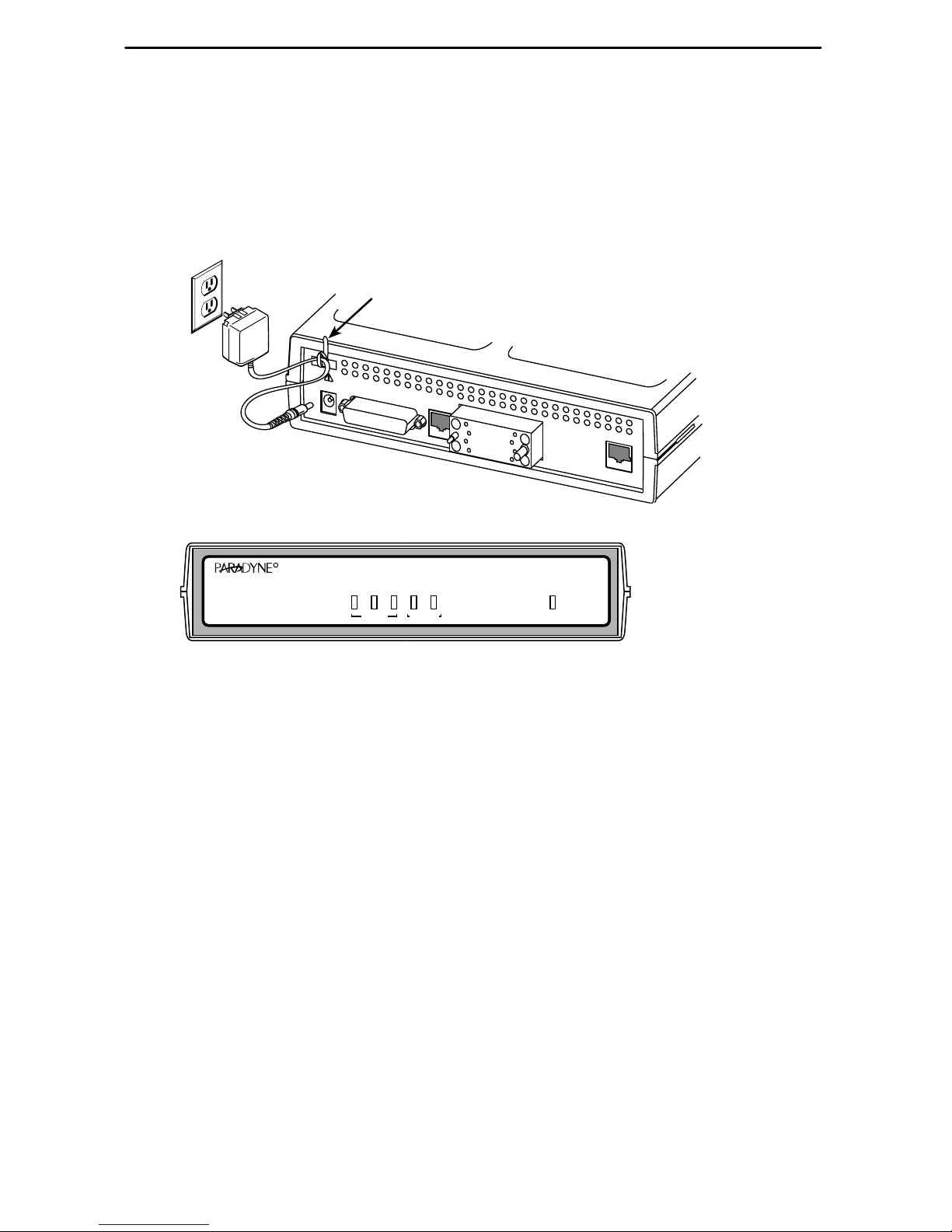
Installing the Power Supply
Procedure
1. Insert the supplied power cord’s plug into the POWER jack.
OK
OK
ALM
TEST
ATM
DSL
NetworkSystem
Port
9783-C
SLV
FrameSaver
®
DSL
SDSL
R
00-16773-01
ETHERNET
P
O
R
T
COM
POWER
NET
Grounded
Power
Outlet
Tie Wrap
2. Plug the power supply into the grounded power outlet and check the LEDs.
If any LEDs light, you have power. If not, refer to
Troubleshooting
in the User’s
Guide for possible explanations.
3. Insert the self-mounting tie wrap in the top left hole (hole with a dark circle around
it) until it snaps securely into place. The tie wrap provides strain relief for the power
cord.
4. Loop the tie wrap around the power cord, thread it through the hole at the base of
the wrap, and pull it snugly around the cord.
Page 5
5
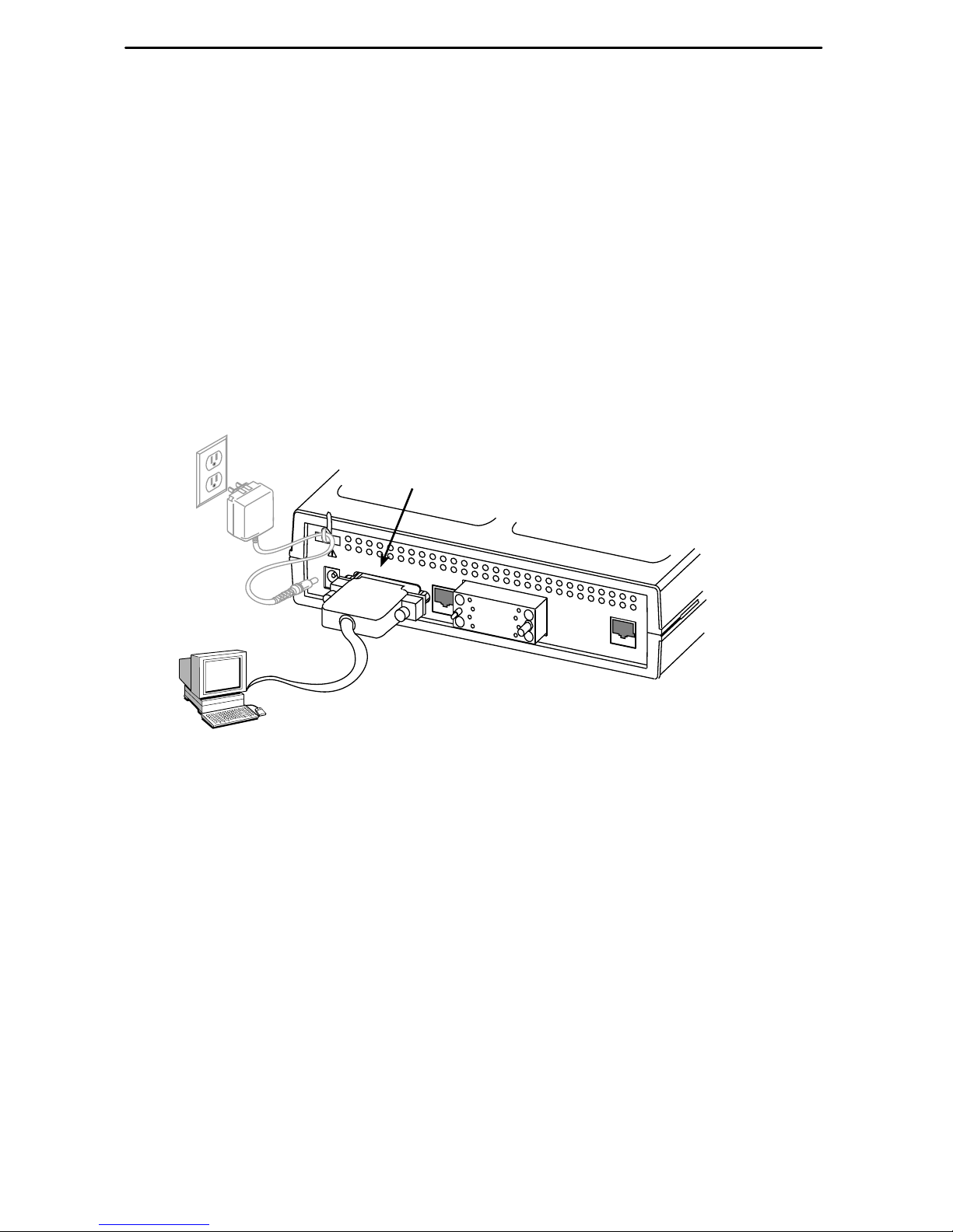
Connecting to an Asynchronous Terminal or PC
A VT100-compatible asynchronous terminal or a PC providing VT100 terminal
emulation must be used to set up access to and management of the unit.
Procedure
1. Configure the terminal or PC so it is compatible with the FrameSaver unit:
– Baud Rate set to 19.2 kbps.
– Character length set to 8 data bits.
– Parity set to none.
– Stop bit set to 1.
– Flow Control set to None.
2. Insert the DB25 end of the EIA-232 cable into the FrameSaver unit’s COM port.
COM
Port
00-16685-01
ETHERNET
P
O
R
T
COM
POWER
NET
VT100
Terminal
or PC
3. Insert the other end of the cable into the terminal or PC.
4. Tighten the screws on each side of the connector to secure the cable.
5. Press Enter on the keyboard to display the Main Menu.
If the Main Menu does not appear, recheck the terminal or PC settings (see
Step 1), or press the Enter key. Refer to
Troubleshooting
in the User’s Guide for
other possible explanations.
Page 6

6
Verifying that Self-Test Passed
To verify that the unit passed its self-test, go to the System and Test Status screen.
Main Menu→Status→System and Test Status
The results of the self-test appear directly under the screen title.
If any failure messages appear, reset the unit by disconnecting, then reconnecting the
power cord. The unit will perform the self-test again. If the failure reappears, call your
service representative for assistance.
A Quick Guide to Configuration
The FrameSaver unit should operate using the default (factory-set) configuration
options, with exception to the changes specified in these installation instructions. Refer
to the following table for help in navigating through the menus.
Press the . . . To . . .
Esc key Go back one screen or menu level. To see a visual
representation of the menu levels, see
Menu Hierarchy
in
the Quick Reference.
Tab key, or
Up (↑), Down (↓),
Left (←) and Right (→)
Arrow keys
Move the cursor from one menu item to the next.
Enter or Return key Complete the menu or option selection.
Spacebar Display the next available setting when changing a
configuration option. All the available settings for an
option appear at the bottom of the screen.
As an example, follow these steps to go to the Configuration Edit/Display menu so you
can start setting up the unit.
Procedure
To load a configuration for editing:
1. From the Main Menu, press the down arrow key twice so the cursor is on
Configuration.
2. Press Enter to display the Configuration menu. The Load Configuration From
menu appears.
3. Press Enter to select Current Configuration (the cursor is already on this
selection). The Configuration Edit/Display menu appears.
This sequence of steps would be shown as the menu selection sequence:
Main Menu→Configuration
Page 7

7
Procedure
To save a configuration option change:
1. Press Ctrl-a to switch to the function keys area at the bottom of the screen.
2. Type s or S (S
ave) and press Enter. The Save Configuration To menu appears.
3. Press Enter again to save your changes to the Current Configuration.
4. Press Esc until the Configuration Edit/Display menu reappears to continue
configuring the unit.
Press Ctrl-a, type m (M
ainMenu), and press Enter to return to the Main Menu.
FrameSaver DSL Installation
An Easy Install screen is provided for custom configurations, but is not required for
normal installation.
Procedure
To use the Easy Install screen:
1. Select the Easy Install feature.
Main Menu→Easy Install
Easy Install Screen Example
main/easy_install 9783
Device Name: Node A 09/11/2000 00:01
EASY INSTALL
Node IP Address: 000.000.000.000
Clear
Node Subnet Mask: 000.000.000.000
Clear
TS Access: VPI,VCI
0 , 35
Create a Dedicated Network Management Link
Ethernet Port Options Screen
Network 1 DSL Line Rate (Kbps) AutoRate
Network 1 FRF.8 Encapsulation Mode Translation
–––––––––––––––––––––––––––––––––––––––––––––––––––––––––––––––––––––––––––––
Ctrl-a to access these functions, ESC for previous menu M
ainMenu Exit
S
ave
Page 8

8
2. Enter the Node IP Address and Node Subnet Mask.
3. Select Create a Dedicated Network Management Link, and enter a DLCI, VPI, and
VCI at the ensuing prompts. The Management Link that is created will be used by
the NOC to access the unit.
4. If the Ethernet port will be used, select the Ethernet Port Options Screen. Enable
the interface. Respond Yes to the prompt Would you like to set the
Node’s Default IP Destination to Ethernet? and configure the
following:
– Enter the IP address and subnet mask for the Ethernet interface.
– Enter the Default Gateway Address (the IP Address that will be used for packets
without a route).
– Press the ESC key to return to the Easy Install screen.
5. The Network 1 FRF.8 Encapsulation Mode default setting is Translation.
Encapsulation Translation used for carrying multiple upper layer user protocols
(frame relay PVC and ATM PVC).
Modify to Transparent to use SLV and multiplexed PVC functions.
6. S
ave the configuration.
7. Install the network cable (see
Connecting to the Network
on page 10).
8. Optionally, install the Ethernet cable (see
Connecting to the Ethernet
on page 11).
9. Install the DTE cable (see
Connecting to the DTE (Router or FRAD)
on page 12).
Physical installation of the unit is complete; the NOC can now remotely access the unit
for additional configuration.
Page 9

9
Completing Setup of the Unit From the NOC
Procedure
1. Access the remote FrameSaver unit on the TS Management Link that was set up
at the remote site.
2. Ping the FrameSaver unit five times within five seconds. The unit automatically
provisions the TS Access VC.
3. Configure specific frame relay options, including the Data Port Frame Relay LMI
settings, and any other configuration options requiring input or changes from the
default settings.
4. Set the SNMP Traps configuration options (see
Configuring SNMP Trap Managers
and Traps
on page 13).
5. Verify the entire path from the remote unit to the NOC NMS is functioning (see
Verifying the End-to-End Path
on page 13).
6. Verify that data is being received (see
Checking That Data is Being Received
on
page 15).
7. Using the OpenLane VC Provisioning Application or Telnet, create all customer
VCs. This requires creation of the DLCI on the user data port, an internal DLCI, the
VPI/VCI on the DSL interface, specifying all parameters (CIR, Be, Bc), and cross
connecting the VPI/VCIs on the network interface to the DLCIs on the V.35 port.
8. Verify that all PVCs, including Management PVCs, are configured; and to see
whether the PVC is active or not (see
Checking PVC Connections
on page 15).
The FrameSaver installation is complete.
In the User’s Guide, see
Operation and Maintenance
for additional status information,
and
Troubleshooting
for additional troubleshooting information.
Page 10

10
Connecting to the Network
Now that the FrameSaver unit is set up, the unit can be connected to the network.
Procedure
1. Use the supplied 6-pin cable for the DSL connection. Insert one end of the cable
into the DSL network interface.
2. Insert the other end of the cable into the modular jack labeled NET.
DSL
Network
00-16685-01
ETHERNET
P
O
R
T
COM
POWER
NET
3. Verify that the Network signal (DSL) LED is green. If so, the network interface is
set up correctly and is operational. If not, make sure both ends of the network
cable are properly seated.
4. Check Health and Status messages in the left column of the System and Test
Status screen.
Main Menu→Status→System and Test Status
Page 11

11
Connecting to the Ethernet
Procedure
1. Insert one 8-pin connector of the Ethernet cable into the Ethernet port.
2. Insert the other end of the cable into the Ethernet interface of the LAN where the
NMS resides.
00-16687-01
NMS
LAN
ETHERNET
P
O
R
T
COM
POWER
NET
3. Check Health and Status messages in the left column of the System and Test
Status screen to verify that there are no Ethernet-related Health and Status
messages.
Main Menu→Status→System and Test Status
If the Ethernet Link Down message appears, make sure both ends of the
Ethernet cable are properly seated.
Page 12

12
Connecting to the DTE (Router or FRAD)
Procedure
1. Connect one end of the DTE’s cable to the user data port.
2. Plug the other end of the cable into the DTE.
3. Tighten the screws on each side of the connector to secure the cable.
00-16689-01
ETHERNET
P
O
R
T
COM
POWER
NET
DTE
4. Verify that the Port OK LED is on. If it is, the port is set up correctly and it is
operational. If not, make sure both ends of the cable are properly seated and
secured.
5. Check Health and Status messages in the left column of the System and Test
Status screen for messages.
Main Menu →Status →System and Test Status
– If System Operational appears, the port interface is set up correctly and
is operational.
– If not, refer to
Status Information
in the
Operation and Maintenance
chapter of
the User’s Guide.
NOTE:
When any error conditions are detected, a status message appears along the
bottom right corner of the screen.
Page 13

13
Configuring SNMP Trap Managers and Traps
Once the FrameSaver unit is connected to the network, SNMP trap managers and
SNMP traps can be configured.
Procedure
To enter SNMP managers and configure traps:
1. Select SNMP Traps.
Main Menu→Configuration→Management and Communication
→
SNMP Traps
2. Configure the following:
– Enable SNMP Traps.
– Identify the total Number of Trap Managers.
– Specify the IP address of the NMS(s) to which traps will be sent.
– Specify the Initial Route Destination for the Trap Manager(s).
– Select desired trap categories.
3. S
ave the configuration.
4. Return to the Main Menu.
Verifying the End-to-End
DSL Provider Management Path
After installation of a remote site unit, run an ATM Ping test from the Hotwire ATM Line
Card.
Procedure
1. From the Hotwire ATM Line Card’s Main Menu, select the A TM Ping test.
Diagnostics→ATM Ping
(D-C)
2. Enter a VPI of 0 and a VCI of 35. Select a Direction of Endpoint. Select Start.
3. If the test is successful, select a Direction of Network. Select Start.
If both tests are successful, the VC has been tested from end to end.
Page 14

14
Provisioning the Customer Data Circuits
Use the OpenLane Provision Circuit screen to add new circuits that start at the
FrameSaver DSL endpoint and traverse the SCM and ATM line card in the Hotwire
GranDSLAM. In addition the default VC sets (from 1 to 4), there is a group of 250 VCs
allocated to each line card that can be assigned to any port on the card. These custom
connections are used to carry the frame relay traffic.
Note that before the custom cross connects are configured, the Maximum VCI
number for the uplink VP to be used by these custom connections must be
specified on the Max VCI per VPI screen and the apply changes executed.
For ATM line cards, custom connections can be used to expand the number of
VCs connected to the card. Each of the 250 VCs can be cross connected from any
VC on the up link to any port on the line card.
The following information is collected by the Provision Circuit process:
Uplink VPI/VCI
Slot number and Port number of DSL connection
Traf fic Profile
DSL link VPI/VCI
Frame relay DLCI (provided by NSP)
Frame relay CIR, B
c
, Be (provided by NSP)
A Circuit ID is then applied to the newly defined circuit, and stored in both the
FrameSaver DSL unit and in OpenLane.
Page 15

15
Checking That Data is Being Received
Procedure
1. From the FrameSaver DSL 9783 Main Menu, select Performance Statistics, and
select either interface’s frame relay statistics.
Main Menu →Status →Performance Statistics →Frame Relay →Net1-FR1
2. Repeatedly Refresh the screen to verify that the Frames Received and Characters
Received counts under the Frame Relay Link statistics are increasing. Verify that
there are no errors under Frame Relay Errors.
If data is not being received or you are receiving errors, check your cable
connections, and replace or repair a damaged cable.
Checking PVC Connections
Check PVC connections to verify that all PVCs, including management PVCs, are
configured, and to see whether the PVC is active or not.
Procedure
1. From the FrameSaver DSL 9783 Main Menu, select PVC Connection Status.
The PVC Connection Status screen shows all PVC connections; the interface
source and DLCI number of the incoming data linked to the interface and DLCI
number for the outgoing data. You can also see whether the PVC is active.
2. Verify that each PVC is active.
– If active, the FrameSaver unit should be passing data.
– If not active, no data traffic can be carried by the PVC. If the PVC is configured
correctly, the circuit may be down.
The FrameSaver installation is complete.
In the User’s Guide, see
Operation and Maintenance
for additional status information,
and
Troubleshooting
for additional troubleshooting information.
Page 16

16
!
Important Safety Instructions
1. Read and follow all warning notices and instructions marked on the product or
included in the manual.
2. Slots and openings in the cabinet are provided for ventilation. To ensure reliable
operation of the product and to protect it from overheating, these slots and
openings must not be blocked or covered.
3. Do not allow anything to rest on the power cord and do not locate the product
where persons will walk on the power cord.
4. Do not attempt to service this product yourself, as opening or removing covers
may expose you to dangerous high voltage points or other risks. Refer all servicing
to qualified service personnel.
5. General purpose cables are provided with this product. Special cables, which may
be required by the regulatory inspection authority for the installation site, are the
responsibility of the customer.
6. When installed in the final configuration, the product must comply with the
applicable Safety Standards and regulatory requirements of the country in which it
is installed. If necessary, consult with the appropriate regulatory agencies and
inspection authorities to ensure compliance.
7. A rare phenomenon can create a voltage potential between the earth grounds of
two or more buildings. If products installed in separate buildings are
interconnected, the voltage potential may cause a hazardous condition. Consult a
qualified electrical consultant to determine whether or not this phenomenon exists
and, if necessary, implement corrective action prior to interconnecting the products.
8. In addition, if the equipment is to be used with telecommunications circuits, take
the following precautions:
— Never install telephone wiring during a lightning storm.
— Never install telephone jacks in wet locations unless the jack is specifically
designed for wet locations.
— Never touch uninsulated telephone wires or terminals unless the telephone
line has been disconnected at the network interface.
— Use caution when installing or modifying telephone lines.
— Avoid using a telephone (other than a cordless type) during an electrical
storm. There may be a remote risk of electric shock from lightning.
— Do not use the telephone to report a gas leak in the vicinity of the leak.
Page 17

17
Canada
Notice to Users of the Canadian Telephone Network
The following notice applies to units that have been CS-03 certified and bear the
Industry Canada certification label.
The Industry Canada label identifies certified equipment. This certification means that
the equipment meets telecommunications network protective, operational and safety
requirements as prescribed in the appropriate Terminal Equipment Technical
Requirements document(s). The Department does not guarantee the equipment will
operate to the user’s satisfaction.
Before installing this equipment, users should ensure that it is permissible to be
connected to the facilities of the local telecommunications company. The equipment
must also be installed using an acceptable method of connection. The customer should
be aware that compliance with the above conditions may not prevent degradation of
service in some situations.
Repairs to certified equipment should be coordinated by a representative designated by
the supplier. Any repairs or alterations made by the user to this equipment, or
equipment malfunctions, may give the telecommunications company cause to request
to disconnect the equipment.
Users should ensure for their own protection that the electrical ground connections of
the power utility, telephone lines and internal metallic water pipe system, if present, are
connected together. This precaution may be particularly important in rural areas.
CAUTION:
Users should not attempt to make such connections themselves, but should
contact the appropriate electric inspection authority, or electrician, as
appropriate.
The Ringer Equivalence Number (REN) assigned to each terminal device provides an
indication of the maximum number of terminals allowed to be connected to a telephone
interface. The termination on an interface may consist of any combination of devices
subject only to the requirement that the sum of the Ringer Equivalence Numbers of all
the devices does not exceed 5.
If your equipment is in need of repair, refer to
Warranty, Sales, Service, and Training
Information
on page 19.
Page 18

18
!
UNITED STA TES – EMI NOTICE
This equipment has been tested and found to comply with the limits for a
Class A digital device, pursuant to Part 15 of the FCC rules. These limits are
designed to provide reasonable protection against harmful interference
when the equipment is operated in a commercial environment. This
equipment generates, uses, and can radiate radio frequency energy and, if
not installed and used in accordance with the instruction manual, may cause
harmful interference to radio communications. Operation of this equipment
in a residential area is likely to cause harmful interference in which case the
user will be required to correct the interference at his own expense.
The authority to operate this equipment is conditioned by the requirements
that no modifications will be made to the equipment unless the changes or
modifications are expressly approved by Paradyne Corporation.
!
CANADA – EMI NOTICE
To Users of Digital Apparatus in Canada:
This Class A digital apparatus meets all requirements of the Canadian
interference-causing equipment regulations.
Cet appareil numérique de la classe A respecte toutes les exigences du
règlement sur le matérial brouilleur du Canada.
Page 19

19
Warranty, Sales, Service, and Training Information
Contact your local sales representative, service representative, or distributor directly for
any help needed. For additional information concerning warranty, sales, service, repair,
installation, documentation, training, distributor locations, or Paradyne worldwide office
locations, use one of the following methods:
Internet: Visit the Paradyne World Wide Web site at www.paradyne.com.
(Be sure to register your warranty at www.paradyne.com/warranty.)
Telephone: Call our automated system to receive current information by fax or to
speak with a company representative.
— Within the U.S.A., call 1-800-870-2221
— Outside the U.S.A., call 1-727-530-2340
Document Feedback
We welcome your comments and suggestions about this document. Please mail them
to Technical Publications, Paradyne Corporation, 8545 126th Ave. N., Largo, FL 33773,
or send e-mail to userdoc@paradyne.com. Include the number and title of this
document in your correspondence. Please include your name and phone number if you
are willing to provide additional clarification.
Trademarks
FrameSaver and Hotwire are registered trademarks of Paradyne Corporation.
OpenLane is a trademark of Paradyne Corporation. All other products and services
mentioned herein are the trademarks, service marks, registered trademarks, or
registered service marks of their respective owners.
Patent Notification
FrameSaver products are protected by U.S. Patents: 5,550,700 and 5,654,966. Other
U.S. patents pending.
Copyright 2000 Paradyne Corporation. Printed in U.S.A.
 Loading...