

Page 1

FrameSaver
®
DSL
Models 9720, 9783, and 9788
User’s Guide
Document No. 9700-A2-GB20-20
December 2002
Page 2

Copyright © 2002 Paradyne Corporation
All rights reserved.
Printed in U.S.A.
Notice
This publication is protected by federal copyright law. No part of this publication may be copied or distributed,
transmitted, transcribed, stored in a retrieval system, or translated into any human or computer language in any form or
by any means, electronic, mechanical, magnetic, manual or otherwise, or disclosed to third parties without the express
written permission of Paradyne Corporation, 8545 126th Ave. N., Largo, FL 33773.
Paradyne Corporation makes no representation or warranties with respect to the contents hereof and specifically
disclaims any implied warranties of merchantability or fitness for a particular purpose. Further, Paradyne Corporation
reserves the right to revise this publication and to make changes from time to time in the contents hereof without
obligation of Paradyne Corporation to notify any person of such revision or changes.
Changes and enhancements to the product and to the information herein will be documented and issued as a new
release to this manual.
Warranty, Sales, Service, and Training Information
Contact your local sales representative, service representative, or distributor directly for any help needed. For additional
information concerning warranty, sales, service, repair, installation, documentation, training, distributor locations, or
Paradyne worldwide office locations, use one of the following methods:
Internet: Visit the Paradyne World Wide Web site at www.paradyne.com. (Be sure to register your warranty at
www.paradyne.com/warranty.)
Telephone: Call our automated system to receive current information by fax or to speak with a company
representative.
— Within the U.S.A., call 1-800-870-2221
— Outside the U.S.A., call 1-727-530-2340
Document Feedback
We welcome your comments and suggestions about this document. Please mail them to Technical Publications,
Paradyne Corporation, 8545 126th Ave. N., Largo, FL 33773, or send e-mail to userdoc@paradyne.com. Include the
number and title of this document in your correspondence. Please include your name and phone number if you are
willing to provide additional clarification.
Tradem ark s
ACCULINK, COMSPHERE, FrameSaver, Hotwire, MVL, NextEDGE, OpenLane, and Performance Wizard are
registered trademarks of Paradyne Corporation. ReachDSL and TruePut are trademarks of Paradyne Corporation. All
other products and services mentioned herein are the trademarks, service marks, registered trademarks, or registered
service marks of their respective owners.
Patent Notification
FrameSaver products are protected by U.S. Patents: 5,550,700 and 5,654,966. Other patents are pending.
A December 2002 9700-A2-GB20-20
Page 3

Contents
About This Guide
Purpose and Intended Audience . . . . . . . . . . . . . . . . . . . . . . . . . . . . . ix
Document Organization . . . . . . . . . . . . . . . . . . . . . . . . . . . . . . . . . . . . ix
Product-Related Documents . . . . . . . . . . . . . . . . . . . . . . . . . . . . . . . . xi
Conventions Used . . . . . . . . . . . . . . . . . . . . . . . . . . . . . . . . . . . . . . . . xii
1 About FrameSaver DSL Devices
System Overview . . . . . . . . . . . . . . . . . . . . . . . . . . . . . . . . . . . . . . . . . 1-1
FrameSaver DSL Features . . . . . . . . . . . . . . . . . . . . . . . . . . . . . . . . . 1-2
CSU/DSU-Specific Features . . . . . . . . . . . . . . . . . . . . . . . . . . . . . 1-2
Router-Specific Features . . . . . . . . . . . . . . . . . . . . . . . . . . . . . . . . 1-2
Diagnostic Feature Set . . . . . . . . . . . . . . . . . . . . . . . . . . . . . . . . . 1-4
Advanced SLM Feature Set. . . . . . . . . . . . . . . . . . . . . . . . . . . . . . 1-6
Network Configuration Examples . . . . . . . . . . . . . . . . . . . . . . . . . . . . . 1-7
OpenLane SLM System . . . . . . . . . . . . . . . . . . . . . . . . . . . . . . . . . . . . 1-9
OpenLane Features . . . . . . . . . . . . . . . . . . . . . . . . . . . . . . . . . . . . 1-9
2 User and Command Line Interfaces, and Basic Operation
Logging On. . . . . . . . . . . . . . . . . . . . . . . . . . . . . . . . . . . . . . . . . . . . . . 2-2
Ending a Session . . . . . . . . . . . . . . . . . . . . . . . . . . . . . . . . . . . . . . 2-3
Main Menu . . . . . . . . . . . . . . . . . . . . . . . . . . . . . . . . . . . . . . . . . . . . . . 2-4
Screen Work Areas . . . . . . . . . . . . . . . . . . . . . . . . . . . . . . . . . . . . . . . 2-5
Navigating Menu-Driven User Interface Screens . . . . . . . . . . . . . . . . . 2-6
Keyboard Keys . . . . . . . . . . . . . . . . . . . . . . . . . . . . . . . . . . . . . . . 2-6
Function Keys . . . . . . . . . . . . . . . . . . . . . . . . . . . . . . . . . . . . . . . . 2-7
Selecting from a Menu . . . . . . . . . . . . . . . . . . . . . . . . . . . . . . . . . . 2-7
Switching Between Screen Areas . . . . . . . . . . . . . . . . . . . . . . . . . 2-8
Selecting a Field for Input . . . . . . . . . . . . . . . . . . . . . . . . . . . . . . . 2-8
Navigating the Router’s CLI . . . . . . . . . . . . . . . . . . . . . . . . . . . . . . . . . 2-9
CLI Keyboard Keys . . . . . . . . . . . . . . . . . . . . . . . . . . . . . . . . . . . . 2-9
9700-A2-GB20-20 December 2002 i
Page 4

Contents
3 Configuration Procedures
Basic Configuration From the User Interface . . . . . . . . . . . . . . . . . . . . 3-2
Configuration Option Areas . . . . . . . . . . . . . . . . . . . . . . . . . . . . . . 3-3
Accessing and Displaying Configuration Options . . . . . . . . . . . . . 3-4
Changing Configuration Options . . . . . . . . . . . . . . . . . . . . . . . . . . 3-5
Saving Configuration Options . . . . . . . . . . . . . . . . . . . . . . . . . . . . 3-5
4 Configuration Options
Using the Easy Install Feature . . . . . . . . . . . . . . . . . . . . . . . . . . . . . . . 4-3
Entering System Information and Setting the System Clock . . . . . . . . 4-8
Changing the Operating Mode . . . . . . . . . . . . . . . . . . . . . . . . . . . . . . . 4-8
Configuration Option Tables . . . . . . . . . . . . . . . . . . . . . . . . . . . . . . . . 4-9
Configuring the Overall System . . . . . . . . . . . . . . . . . . . . . . . . . . . . . . 4-10
Configuring Frame Relay and LMI for the CSU/DSU . . . . . . . . . . 4-10
Configuring Class of Service Definitions . . . . . . . . . . . . . . . . . . . . 4-13
Code Point Definitions . . . . . . . . . . . . . . . . . . . . . . . . . . . . . . . . . . 4-15
Configuring Service Level Verification Options . . . . . . . . . . . . . . . 4-16
Configuring General System Options . . . . . . . . . . . . . . . . . . . . . . 4-19
Configuring Network Interfaces . . . . . . . . . . . . . . . . . . . . . . . . . . . . . . 4-20
Configuring the Network Physical Interface . . . . . . . . . . . . . . . . . . 4-20
Configuring Frame Relay for the Network Interface . . . . . . . . . . . 4-23
Configuring DLCI Records for the Network Interface (9720) . . . . . 4-23
Configuring Circuit Records for the Network Interface (9783, 9788) 4-24
Configuring ATM for the Network Interface (9783, 9788) . . . . . . . 4-27
Configuring the User Data or Virtual Router Port . . . . . . . . . . . . . . . . . 4-28
Configuring the CSU/DSU’s Data Port Physical Interface . . . . . . . 4-28
Configuring Frame Relay on the CSU/DSU’s Data Port . . . . . . . . 4-30
Configuring DLCI Records . . . . . . . . . . . . . . . . . . . . . . . . . . . . . . . 4-32
Configuring PVC Connections . . . . . . . . . . . . . . . . . . . . . . . . . . . . . . . 4-35
Configuring the IP Path List . . . . . . . . . . . . . . . . . . . . . . . . . . . . . . . . . 4-37
Setting Up Management and Communication . . . . . . . . . . . . . . . . . . . 4-38
Configuring Node IP Information . . . . . . . . . . . . . . . . . . . . . . . . . . 4-38
Configuring Management PVCs . . . . . . . . . . . . . . . . . . . . . . . . . . 4-41
Configuring General SNMP Management . . . . . . . . . . . . . . . . . . . 4-46
Configuring Telnet and/or FTP Sessions. . . . . . . . . . . . . . . . . . . . 4-48
Configuring SNMP NMS Security . . . . . . . . . . . . . . . . . . . . . . . . . 4-51
Configuring SNMP Traps. . . . . . . . . . . . . . . . . . . . . . . . . . . . . . . . 4-53
Configuring Ethernet Management . . . . . . . . . . . . . . . . . . . . . . . . 4-57
Configuring the Communication Port. . . . . . . . . . . . . . . . . . . . . . . 4-59
Configuring the COM Port to Support an External Modem . . . . . . 4-63
ii December 2002 9700-A2-GB20-20
Page 5

5 Configuring the FrameSaver DSL Router
FrameSaver DSL Router Overview . . . . . . . . . . . . . . . . . . . . . . . . . . . 5-2
IP Routing . . . . . . . . . . . . . . . . . . . . . . . . . . . . . . . . . . . . . . . . . . . . . . 5-3
Address Resolution Protocol . . . . . . . . . . . . . . . . . . . . . . . . . . . . . . . . 5-3
Proxy ARP . . . . . . . . . . . . . . . . . . . . . . . . . . . . . . . . . . . . . . . . . . . . . . 5-3
Interface Configuration . . . . . . . . . . . . . . . . . . . . . . . . . . . . . . . . . . . . . 5-4
Network Address Translation . . . . . . . . . . . . . . . . . . . . . . . . . . . . . . . . 5-5
IP Options Processing . . . . . . . . . . . . . . . . . . . . . . . . . . . . . . . . . . 5-5
Applications Supported by NAT. . . . . . . . . . . . . . . . . . . . . . . . . . . 5-5
NAT Configuration Example . . . . . . . . . . . . . . . . . . . . . . . . . . . . . 5-6
Network Address Port Translation . . . . . . . . . . . . . . . . . . . . . . . . . . . . 5-8
NAPT Configuration Example . . . . . . . . . . . . . . . . . . . . . . . . . . . . 5-8
NAT and NAPT Configuration Example. . . . . . . . . . . . . . . . . . . . . 5-10
Dynamic Host Configuration Protocol Server. . . . . . . . . . . . . . . . . . . . 5-11
DHCP Server with NAT Configuration Example . . . . . . . . . . . . . . 5-12
DHCP Server at Remote Site Configuration Example. . . . . . . . . . 5-13
DHCP Relay Agent . . . . . . . . . . . . . . . . . . . . . . . . . . . . . . . . . . . . . . . 5-13
DHCP Relay Configuration Example . . . . . . . . . . . . . . . . . . . . . . . 5-14
Router Security . . . . . . . . . . . . . . . . . . . . . . . . . . . . . . . . . . . . . . . . . . 5-15
IP Router Filtering . . . . . . . . . . . . . . . . . . . . . . . . . . . . . . . . . . . . . 5-15
Bridge Filtering. . . . . . . . . . . . . . . . . . . . . . . . . . . . . . . . . . . . . . . . 5-15
IP Filtering . . . . . . . . . . . . . . . . . . . . . . . . . . . . . . . . . . . . . . . . . . . 5-16
Land Bug Prevention . . . . . . . . . . . . . . . . . . . . . . . . . . . . . . . . . . . 5-16
Smurf Attack Prevention . . . . . . . . . . . . . . . . . . . . . . . . . . . . . . . . 5-16
Verifying the End-to-End Management Path . . . . . . . . . . . . . . . . . . . . 5-17
Provisioning the Router Interface. . . . . . . . . . . . . . . . . . . . . . . . . . . . . 5-17
Configuring the Router Using Terminal Emulation . . . . . . . . . . . . . . . . 5-18
Uploading and Downloading the Router Configuration Via the CLI 5-18
Contents
6 Security and Logins
Limiting Access . . . . . . . . . . . . . . . . . . . . . . . . . . . . . . . . . . . . . . . . . . 6-2
Controlling Asynchronous Terminal Access. . . . . . . . . . . . . . . . . . . . . 6-3
Controlling External COM Port Device Access . . . . . . . . . . . . . . . . . . 6-4
Controlling Telnet and FTP Access . . . . . . . . . . . . . . . . . . . . . . . . . . . 6-4
Controlling SNMP Access . . . . . . . . . . . . . . . . . . . . . . . . . . . . . . . . . . 6-8
9700-A2-GB20-20 December 2002 iii
Limiting Telnet Access . . . . . . . . . . . . . . . . . . . . . . . . . . . . . . . . . . 6-5
Limiting FTP Access . . . . . . . . . . . . . . . . . . . . . . . . . . . . . . . . . . . 6-6
Limiting Telnet or FTP Access Over the TS Management Link. . . 6-7
Disabling SNMP Access . . . . . . . . . . . . . . . . . . . . . . . . . . . . . . . . 6-8
Assigning SNMP Community Names and Access Levels . . . . . . . 6-9
Limiting SNMP Access Through IP Addresses . . . . . . . . . . . . . . . 6-10
Page 6

Contents
Controlling Router CLI Access . . . . . . . . . . . . . . . . . . . . . . . . . . . . . . . 6-11
Access Levels (Command Modes) . . . . . . . . . . . . . . . . . . . . . . . . 6-11
Changing Access Levels . . . . . . . . . . . . . . . . . . . . . . . . . . . . . . . . 6-12
Creating a Login for the User Interface . . . . . . . . . . . . . . . . . . . . . . . . 6-13
Modifying a Login . . . . . . . . . . . . . . . . . . . . . . . . . . . . . . . . . . . . . . . . . 6-14
Deleting a Login . . . . . . . . . . . . . . . . . . . . . . . . . . . . . . . . . . . . . . . . . . 6-14
7 Operation and Maintenance
Displaying Identity System Information . . . . . . . . . . . . . . . . . . . . . . . . 7-2
Viewing LEDs and Control Leads . . . . . . . . . . . . . . . . . . . . . . . . . . . . 7-3
LED Descriptions . . . . . . . . . . . . . . . . . . . . . . . . . . . . . . . . . . . . . . 7-5
Control Lead Descriptions . . . . . . . . . . . . . . . . . . . . . . . . . . . . . . . 7-6
Device Messages . . . . . . . . . . . . . . . . . . . . . . . . . . . . . . . . . . . . . . . . . 7-8
Router CLI Messages . . . . . . . . . . . . . . . . . . . . . . . . . . . . . . . . . . . . . 7-13
Status Information . . . . . . . . . . . . . . . . . . . . . . . . . . . . . . . . . . . . . . . . 7-18
System and Test Status Messages . . . . . . . . . . . . . . . . . . . . . . . . . . . 7-19
Self-Test Results Messages . . . . . . . . . . . . . . . . . . . . . . . . . . . . . 7-19
Last Reset . . . . . . . . . . . . . . . . . . . . . . . . . . . . . . . . . . . . . . . . . . . 7-19
Health and Status Messages. . . . . . . . . . . . . . . . . . . . . . . . . . . . . 7-20
Test Status Messages . . . . . . . . . . . . . . . . . . . . . . . . . . . . . . . . . . 7-22
IP Path Connection Status . . . . . . . . . . . . . . . . . . . . . . . . . . . . . . . . . . 7-22
PVC Connection Status . . . . . . . . . . . . . . . . . . . . . . . . . . . . . . . . . . . . 7-24
Network Interface Status . . . . . . . . . . . . . . . . . . . . . . . . . . . . . . . . . . . 7-26
IP Routing Table (Management Traffic) . . . . . . . . . . . . . . . . . . . . . . . . 7-27
Performance Statistics . . . . . . . . . . . . . . . . . . . . . . . . . . . . . . . . . . . . . 7-29
Service Level Verification Performance Statistics . . . . . . . . . . . . . 7-30
DLCI Performance Statistics . . . . . . . . . . . . . . . . . . . . . . . . . . . . . 7-34
Additional Performance Statistics for IP Enabled DLCI . . . . . . . . . 7-35
Frame Relay Performance Statistics . . . . . . . . . . . . . . . . . . . . . . . 7-36
ATM Performance Statistics (9783, 9788) . . . . . . . . . . . . . . . . . . . 7-38
VCC Performance Statistics (9783, 9788) . . . . . . . . . . . . . . . . . . . 7-39
SHDSL Line Performance Statistics (9788). . . . . . . . . . . . . . . . . . 7-40
Ethernet Performance Statistics . . . . . . . . . . . . . . . . . . . . . . . . . . 7-41
Clearing Performance Statistics . . . . . . . . . . . . . . . . . . . . . . . . . . 7-42
Trap Event Log. . . . . . . . . . . . . . . . . . . . . . . . . . . . . . . . . . . . . . . . . . . 7-43
FTP File Transfers . . . . . . . . . . . . . . . . . . . . . . . . . . . . . . . . . . . . . . . . 7-44
Initiating an FTP Session . . . . . . . . . . . . . . . . . . . . . . . . . . . . . . . . 7-45
Upgrading System Software . . . . . . . . . . . . . . . . . . . . . . . . . . . . . 7-46
Determining Whether a Download Is Completed. . . . . . . . . . . . . . 7-47
Activating Software . . . . . . . . . . . . . . . . . . . . . . . . . . . . . . . . . . . . 7-47
Transferring Collected Data . . . . . . . . . . . . . . . . . . . . . . . . . . . . . . 7-48
iv December 2002 9700-A2-GB20-20
Page 7

8Troubleshooting
Problem Indicators . . . . . . . . . . . . . . . . . . . . . . . . . . . . . . . . . . . . . . . . 8-2
Resetting the Unit and Restoring Communication . . . . . . . . . . . . . . . . 8-3
Resetting the Unit from the Control Menu . . . . . . . . . . . . . . . . . . . 8-3
Resetting the Unit By Cycling the Power . . . . . . . . . . . . . . . . . . . . 8-3
Restoring Communication with an Improperly Configured Unit . . . 8-4
Troubleshooting Management Link Feature . . . . . . . . . . . . . . . . . . . . 8-5
LMI Packet Capture Utility Feature . . . . . . . . . . . . . . . . . . . . . . . . . . . 8-5
Viewing LMI Captured Packets from the User Interface . . . . . . . . 8-6
Telnet . . . . . . . . . . . . . . . . . . . . . . . . . . . . . . . . . . . . . . . . . . . . . . . . . . 8-7
Alarms . . . . . . . . . . . . . . . . . . . . . . . . . . . . . . . . . . . . . . . . . . . . . . . . . 8-8
Viewing the Trap Event Log . . . . . . . . . . . . . . . . . . . . . . . . . . . . . . . . . 8-11
Troubleshooting Tables . . . . . . . . . . . . . . . . . . . . . . . . . . . . . . . . . . . . 8-11
Device Problems . . . . . . . . . . . . . . . . . . . . . . . . . . . . . . . . . . . . . . 8-12
ATM Problems . . . . . . . . . . . . . . . . . . . . . . . . . . . . . . . . . . . . . . . . 8-13
Frame Relay PVC Problems . . . . . . . . . . . . . . . . . . . . . . . . . . . . . 8-14
Tests Available . . . . . . . . . . . . . . . . . . . . . . . . . . . . . . . . . . . . . . . . . . . 8-15
Test Timeout Feature . . . . . . . . . . . . . . . . . . . . . . . . . . . . . . . . . . 8-16
Starting and Stopping a Test . . . . . . . . . . . . . . . . . . . . . . . . . . . . . . . . 8-17
Aborting All Tests. . . . . . . . . . . . . . . . . . . . . . . . . . . . . . . . . . . . . . 8-17
PVC Tests . . . . . . . . . . . . . . . . . . . . . . . . . . . . . . . . . . . . . . . . . . . . . . 8-18
PVC Loopback. . . . . . . . . . . . . . . . . . . . . . . . . . . . . . . . . . . . . . . . 8-19
Send Pattern . . . . . . . . . . . . . . . . . . . . . . . . . . . . . . . . . . . . . . . . . 8-19
Monitor Pattern . . . . . . . . . . . . . . . . . . . . . . . . . . . . . . . . . . . . . . . 8-20
Connectivity . . . . . . . . . . . . . . . . . . . . . . . . . . . . . . . . . . . . . . . . . . 8-20
Network ATM Loopback . . . . . . . . . . . . . . . . . . . . . . . . . . . . . . . . . . . . 8-21
Data Port Physical Tests . . . . . . . . . . . . . . . . . . . . . . . . . . . . . . . . . . . 8-23
DTE Loopback . . . . . . . . . . . . . . . . . . . . . . . . . . . . . . . . . . . . . . . . 8-23
IP Ping Test . . . . . . . . . . . . . . . . . . . . . . . . . . . . . . . . . . . . . . . . . . . . . 8-24
IP Ping Test – Procedure 1 . . . . . . . . . . . . . . . . . . . . . . . . . . . . . . 8-28
IP Ping Test – Procedure 2 . . . . . . . . . . . . . . . . . . . . . . . . . . . . . . 8-29
Lamp Test . . . . . . . . . . . . . . . . . . . . . . . . . . . . . . . . . . . . . . . . . . . . . . 8-30
Contents
9 Setting Up OpenLane for FrameSaver Device
OpenLane Support of FrameSaver Devices . . . . . . . . . . . . . . . . . . . . 9-2
Setting Up the OpenLane SLM System . . . . . . . . . . . . . . . . . . . . . . . . 9-2
Setting Up FrameSaver Support . . . . . . . . . . . . . . . . . . . . . . . . . . . . . 9-3
Ordering Advanced SLM Feature Set Activations . . . . . . . . . . . . . . . . 9-4
9700-A2-GB20-20 December 2002 v
To Find Your License Key Number . . . . . . . . . . . . . . . . . . . . . . . . 9-4
The Activation Certificate . . . . . . . . . . . . . . . . . . . . . . . . . . . . . . . . 9-5
Page 8

Contents
Administering and Managing Advanced SLM Activations . . . . . . . . . . 9-6
Entering an Activation Certificate. . . . . . . . . . . . . . . . . . . . . . . . . . 9-7
Checking Activation Certificate Status. . . . . . . . . . . . . . . . . . . . . . 9-7
Scheduling Activations. . . . . . . . . . . . . . . . . . . . . . . . . . . . . . . . . . 9-8
Checking the Status of Scheduled Activations . . . . . . . . . . . . . . . 9-9
Canceling Scheduled Activations . . . . . . . . . . . . . . . . . . . . . . . . . 9-9
Accessing and Printing the Certificate Summary Report. . . . . . . . 9-9
10 Setting Up Network Health for FrameSaver Device
Installation and Setup of Network Health . . . . . . . . . . . . . . . . . . . . . . . 10-2
Discovering FrameSaver Elements . . . . . . . . . . . . . . . . . . . . . . . . . . . 10-3
Configuring the Discovered Elements . . . . . . . . . . . . . . . . . . . . . . . . . 10-4
Grouping Elements for Reports . . . . . . . . . . . . . . . . . . . . . . . . . . . . . . 10-5
Generating Reports for a Group. . . . . . . . . . . . . . . . . . . . . . . . . . . . . . 10-6
About Service Level Reports . . . . . . . . . . . . . . . . . . . . . . . . . . . . . 10-6
About At-a-Glance Reports . . . . . . . . . . . . . . . . . . . . . . . . . . . . . . 10-6
About Trend Reports . . . . . . . . . . . . . . . . . . . . . . . . . . . . . . . . . . . 10-7
Printed Reports . . . . . . . . . . . . . . . . . . . . . . . . . . . . . . . . . . . . . . . 10-7
Reports Applicable to FrameSaver Devices . . . . . . . . . . . . . . . . . . . . 10-7
A Menu Hierarchy
Menus . . . . . . . . . . . . . . . . . . . . . . . . . . . . . . . . . . . . . . . . . . . . . . . . . A-1
FrameSaver DSL CSU/DSUs Menu Structure . . . . . . . . . . . . . . . A-2
FrameSaver DSL Routers Menu Structure . . . . . . . . . . . . . . . . . . A-4
B SNMP MIBs, Traps, and RMON Alarm Defaults
MIB Support . . . . . . . . . . . . . . . . . . . . . . . . . . . . . . . . . . . . . . . . . . . . . B-2
Downloading MIBs and SNMP Traps. . . . . . . . . . . . . . . . . . . . . . . . . . B-2
System Group (mib-2) . . . . . . . . . . . . . . . . . . . . . . . . . . . . . . . . . . . . . B-3
FrameSaver Unit’s sysDescr (system 1) . . . . . . . . . . . . . . . . . . . . B-3
FrameSaver Unit’s sysObjectID (system 2). . . . . . . . . . . . . . . . . . B-3
Interfaces Group (mib-2) . . . . . . . . . . . . . . . . . . . . . . . . . . . . . . . . . . . B-4
Paradyne Indexes to the Interface Table (ifTable). . . . . . . . . . . . . B-4
NetScout Probe Indexes to the Interface Table (ifTable). . . . . . . . B-5
Standards Compliance for SNMP Traps . . . . . . . . . . . . . . . . . . . . . . . B-6
Trap: warmStart . . . . . . . . . . . . . . . . . . . . . . . . . . . . . . . . . . . . . . . B-7
Trap: authenticationFailure . . . . . . . . . . . . . . . . . . . . . . . . . . . . . . B-7
Trap: linkUp and linkDown . . . . . . . . . . . . . . . . . . . . . . . . . . . . . . . B-8
Trap: enterprise-Specific . . . . . . . . . . . . . . . . . . . . . . . . . . . . . . . . B-11
Trap: RMON-Specific. . . . . . . . . . . . . . . . . . . . . . . . . . . . . . . . . . . B-13
vi December 2002 9700-A2-GB20-20
Page 9

RMON Alarm and Event Defaults . . . . . . . . . . . . . . . . . . . . . . . . . . . . B-14
Network Physical Interface Alarm Defaults . . . . . . . . . . . . . . . . . . B-15
Frame Relay Link Alarm Defaults . . . . . . . . . . . . . . . . . . . . . . . . . B-15
DLCI Alarm Defaults . . . . . . . . . . . . . . . . . . . . . . . . . . . . . . . . . . . B-17
OID Cross-References . . . . . . . . . . . . . . . . . . . . . . . . . . . . . . . . . . . . . B-19
C Router CLI Commands, Codes, and Designations
CLI Commands . . . . . . . . . . . . . . . . . . . . . . . . . . . . . . . . . . . . . . . . . . C-1
Pager Command . . . . . . . . . . . . . . . . . . . . . . . . . . . . . . . . . . . . . . C-3
Access Control Commands . . . . . . . . . . . . . . . . . . . . . . . . . . . . . . C-3
Configuration Commands . . . . . . . . . . . . . . . . . . . . . . . . . . . . . . . C-4
Interface Commands . . . . . . . . . . . . . . . . . . . . . . . . . . . . . . . . . . . C-5
IP Routing Commands. . . . . . . . . . . . . . . . . . . . . . . . . . . . . . . . . . C-8
Bridge Commands . . . . . . . . . . . . . . . . . . . . . . . . . . . . . . . . . . . . . C-9
ARP Commands . . . . . . . . . . . . . . . . . . . . . . . . . . . . . . . . . . . . . . C-11
NAT Commands . . . . . . . . . . . . . . . . . . . . . . . . . . . . . . . . . . . . . . C-12
DHCP Server Commands . . . . . . . . . . . . . . . . . . . . . . . . . . . . . . . C-15
DHCP Relay Agent Commands. . . . . . . . . . . . . . . . . . . . . . . . . . . C-18
Filter (access-list) Commands . . . . . . . . . . . . . . . . . . . . . . . . . . . . C-19
Diagnostic Commands. . . . . . . . . . . . . . . . . . . . . . . . . . . . . . . . . . C-23
Show Commands . . . . . . . . . . . . . . . . . . . . . . . . . . . . . . . . . . . . . C-25
Ethernet Type Codes . . . . . . . . . . . . . . . . . . . . . . . . . . . . . . . . . . . . . . C-29
Protocol and Port Designations . . . . . . . . . . . . . . . . . . . . . . . . . . . . . . C-31
ICMP Designations . . . . . . . . . . . . . . . . . . . . . . . . . . . . . . . . . . . . C-31
TCP Port Designations . . . . . . . . . . . . . . . . . . . . . . . . . . . . . . . . . C-33
UDP Port Designations . . . . . . . . . . . . . . . . . . . . . . . . . . . . . . . . . C-34
Contents
D Router Command Line Summaries and Shortcuts
CLI Summaries . . . . . . . . . . . . . . . . . . . . . . . . . . . . . . . . . . . . . . . . . . D-1
E Connectors, Cables, and Pin Assignments
Rear Panels . . . . . . . . . . . . . . . . . . . . . . . . . . . . . . . . . . . . . . . . . . . . . E-2
DSL Network Interface and Cable . . . . . . . . . . . . . . . . . . . . . . . . . . . . E-4
Model 9783 COM Port Connector . . . . . . . . . . . . . . . . . . . . . . . . . . . . E-5
Model 9720 and 9788 COM Port Connector . . . . . . . . . . . . . . . . . . . . E-5
Ethernet Port Connector . . . . . . . . . . . . . . . . . . . . . . . . . . . . . . . . . . . E-6
9700-A2-GB20-20 December 2002 vii
Show Command Summary . . . . . . . . . . . . . . . . . . . . . . . . . . . . . . D-2
Access Control and System Level Command Summary . . . . . . . . D-3
CLI Command Summary . . . . . . . . . . . . . . . . . . . . . . . . . . . . . . . . D-4
CLI Command Default Settings . . . . . . . . . . . . . . . . . . . . . . . . . . . D-6
Page 10

Contents
Model 9720 and 9783 CSU/DSU Data Port Connector . . . . . . . . . . . . E-7
Standard V.35 Straight-through Cable. . . . . . . . . . . . . . . . . . . . . . E-7
Model 9788 CSU/DSU Data Port Connector . . . . . . . . . . . . . . . . . . . . E-8
EIA-530-A-to-V.35 Adapter . . . . . . . . . . . . . . . . . . . . . . . . . . . . . . . . . E-9
EIA-530-A-to-X.21 Adapter . . . . . . . . . . . . . . . . . . . . . . . . . . . . . . . . . E-10
Configuring an External Modem. . . . . . . . . . . . . . . . . . . . . . . . . . . . . . E-11
DB25-to-DB25 Crossover Cable . . . . . . . . . . . . . . . . . . . . . . . . . . E-12
DB9-to-DB25 Crossover Cable . . . . . . . . . . . . . . . . . . . . . . . . . . . E-13
F Technical Specifications
G Equipment List
Equipment . . . . . . . . . . . . . . . . . . . . . . . . . . . . . . . . . . . . . . . . . . . . . . G-1
Cables . . . . . . . . . . . . . . . . . . . . . . . . . . . . . . . . . . . . . . . . . . . . . . . . . G-5
Index
viii December 2002 9700-A2-GB20-20
Page 11

About This Guide
Purpose and Intended Audience
This document contains information that applies to FrameSaver DSL (Digital
Subscriber Line) 9720, 9783, and 9788 CSU/DSUs (Channel Service Unit/Data
Service Units) and FrameSaver DSL routers running firmware release level 2.0.4
and above. Features slated for firmware release 2.1, such as Telnet capability, are
described in this manual but may not be immediately available in all models.
It is intended for system designers, engineers, administrators, and operators who
are familiar with the operation of digital data communications equipment and frame
relay networks.
NOTE:
In this manual, CSU/DSU refers to the line termination capability of the DSL
endpoint, and does not imply association with traditional T1 or DDS
equipment.
Document Organization
Section Description
Chapter 1,
FrameSaver DSL Devices
Chapter 2,
Command Line Interfaces,
and Basic Operation
Chapter 3,
Procedures
Chapter 4,
Options
About
User and
Configuration
Configuration
Identifies how FrameSaver DSL devices fit into
Paradyne’s Service Level Management (SLM) solution,
and describes the unit’s basic, unique, and advanced
features.
Shows how to navigate the menu-driven user interface
and the router’s Command Line Interface (CLI).
Shows how to access and save configuration options.
Describes the configuration options available for the
devices.
Chapter 5,
FrameSaver DSL Router
9700-A2-GB20-20 December 2002 ix
Configuring the
Describes the FrameSaver DSL Router’s interfaces and
features, with sample router scenarios, and how to
configure the router.
Page 12

About This Guide
Section Description
Chapter 6,
Security and
Logins
Chapter 7,
Operation and
Maintenance
Chapter 8,
Chapter 9,
Troubleshooting
Setting Up
OpenLane for FrameSaver
Device
Chapter 10,
Setting Up
Network Health for
FrameSaver Device
Appendix A,
Appendix B,
Menu Hierarchy
SNMP MIBs,
Traps, and RMON Alarm
Defaults
Appendix C,
Router CLI
Commands, Codes, and
Designations
Provides procedures for controlling access to the device
and setting up logins.
Provides procedures to display device identification
information and perform file transfers, as well as how to
display and interpret status and statistical information.
Provides device problem indicators, problem resolution,
alarm conditions, troubleshooting, and test procedures.
Identifies where installation and setup information is
located and how FrameSaver devices are supported.
Describes setup of Concord’s Network Health application
to create reports for FrameSaver devices.
Contains a graphical representation of how the
menu-driven user interface screens are organized.
Identifies the MIBs supported, lists the device’s
compliance with SNMP format standards and special
operational trap features, describes the RMON-specific
user history groups, and presents alarm and event
defaults.
Describes the configuration options available on the
FrameSaver DSL Router, and the minimum access level
for each command.
Appendix D,
Command Line Summaries
and Shortcuts
Appendix E,
Cables, and Pin Assignments
Appendix F,
Router
Connectors,
Technical
Provides a summary of commands, with abbreviated
syntax that can be entered, and the default setting for
each command.
Shows the unit’s rear panels, tells what cables are
needed, and provides pin assignments for interfaces and
cables.
Technical Specifications.
Specifications
Appendix G,
Index
Equipment List
Equipment List.
Lists key terms, acronyms, concepts, and sections.
A master glossary of terms and acronyms used in Paradyne documents is
available on the World Wide Web at www.paradyne.com. Select
Technical Manuals
→
Technical Glossary
.
Library
→
x December 2002 9700-A2-GB20-20
Page 13

Product-Related Documents
Document Number Document Title
Paradyne FrameSaver Documentation:
About This Guide
9000-A2-GB20
9000-A2-GK43
9700-A2-GL10
9700-A2-GL11
9720-A2-GN10
9783-A2-GN10
9783-A2-GN11
9788-A2-GN10
9788-A2-GN11
Paradyne Hotwire Documentation:
8000-A2-GB26
8335-A2-GB20
8820-A2-GN20
Paradyne OpenLane NMS Documentation:
Configuring Frame Relay Service Over DSL
FrameSaver SLV Activation Instructions
FrameSaver DSL CSU/DSU, Models 9783 and 9788,
Quick Reference
FrameSaver DSL Router, Models 9783 and 9788, Quick
Reference
FrameSaver DSL 9720 CSU/DSU Installation Instructions
FrameSaver DSL 9783 CSU/DSU Installation Instructions
FrameSaver DSL 9783 Router Installation Instructions
FrameSaver DSL 9788 CSU/DSU Installation Instructions
FrameSaver DSL 9788 Router Installation Instructions
Hotwire MVL, ReachDSL, RADSL, IDSL, and SDSL Cards,
Models 8310, 8312/8314, 8510/8373/8374, 8303/8304, and
8343/8344, User’s Guide
Hotwire ATM Line Cards, Models 8335, 8355, 8365, and 8385,
User’s Guide
Hotwire 8820 GranDSLAM Installation Guide
7800-A2-GB30
7800-A2-GB32
7800-A2-GZ46
NetScout Documentation:
2930-170
2930-610
2930-620
2930-788
Concord Communications Documentation:
09-10010-005
09-10020-005
09-10050-002
09-10070-001
OpenLane SLM Reports Reference Guide
OpenLane SLM Administrator’s Guide
OpenLane SLM Oracle Database Administration Instructions
NetScout Probe User Guide
NetScout Manager/Plus User Guide
NetScout Manager/Plus & NetScout Server Administrator Guide
NetScout Manager Plus Set Up & Installation Guide
Network Health User Guide
Network Health Installation Guide
Network Health – Traffic Accountant Reports Guide
Network Health Reports Guide
Complete Paradyne documentation for this product is available at
www.paradyne.com. Select
Library →Technical Manuals.
9700-A2-GB20-20 December 2002 xi
Page 14

About This Guide
To order a paper copy of this manual:
Conventions Used
Convention Interpretation
Within the U.S.A., call 1-800-PARADYNE (1-800-727-2396)
Outside the U.S.A., call 1-727-530-8623
[ ]
{}
|
[{ }]
Italics
Bold
x.x.x.x
xx:xx:xx:xx:xx:xx
Main Menu →Status
Text highlighted in blue A hyperlink to additional information when viewing this
Brackets indicate an optional element.
Braces indicate a required entry.
Vertical bars separate mutually exclusive elements. Enter
one element only.
Braces within brackets indicate a required choice within an
optional element.
Entry is a variable, which must be supplied by the operator.
Entry, or the minimum characters that can be entered, must
be typed as shown
32-bit IP address and mask information where x is an 8-bit
weighted decimal notation.
MAC address information, where x is a hexadecimal
notation.
Menu selection indicates a selection sequence to be made
from a menu (e.g., select Status from the Main Menu).
manual online. Click on the highlighted text.
xii December 2002 9700-A2-GB20-20
Page 15

About FrameSaver DSL Devices
This chapter includes the following:
System Overview
FrameSaver DSL Features
CSU/DSU-Specific Features
—
—
Router-Specific Features
—
Diagnostic Feature Set
—
Advanced SLM Feature Set
on page 1-2
1
System Overview
The Paradyne system solution consists of:
This solution controls network costs by providing increased manageability,
monitoring, and diagnostics to identify and troubleshoot problems more quickly.
FrameSaver DSL devices operate with other FrameSaver devices, and are also
compatible with Concord Communication’s Network Health software.
Network Configuration Examples
OpenLane SLM System
FrameSaver® DSL (Digital Subscriber Line) CSU/DSU (Channel Service
Unit/Data Service Unit)
FrameSaver DSL Router
Hotwire® ATM (Asynchronous Transfer Mode) Line Card in the Hotwire
GranDSLAM, or with another vendor’s DSLAM (Digital Subscriber Line Access
Multiplexer)
Call Paradyne for compatible DSLAMs (see
Training Information
OpenLane® SLM (Service Level Management) System
on page 1-9
in the front of this document for the phone number).
on page 1-7
Warranty, Sales, Service, and
9700-A2-GB20-20 December 2002 1-1
Page 16

1. About FrameSaver DSL Devices
FrameSaver DSL Features
Based upon the model ordered, or whether the device has been upgraded to
Service Level Verifier (SLV) capability, FrameSaver DSL devices have the
Diagnostic Feature Set or Advanced SLM Feature Set, each providing different
levels of intelligence for monitoring, managing, and reporting performance of the
device.
For features specific to the DSL CSU/DSU or router, see
Features
CSU/DSU-Specific Features
The following features only apply to the DSL CSU/DSU:
Two Interfaces. Provides two interfaces for traffic:
— Synchronous DTE port for user data
— Ethernet Interface for management data
Upstream Pipelining. Provides pipelining capability into the Wide Area
Network (WAN) for reduced latency, where groups of bytes are transmitted as
soon as they are received, rather than waiting for the entire frame to be
collected before sending.
LMI Protocol Support. Automatically detects and initializes the Local
Management Interface (LMI) protocol type on the user data port.
Router-Specific Features
The following features only apply to the DSL router:
and
Router-Specific Features
CSU/DSU-Specific
.
Ethernet Interface. Supports user data and management traffic. An LED is
also provided to view the status of the interface.
In-Band Router Management. Permits the router to be managed via
customer data PVCs and EDLCIs by assigning an IP address for router
management that is different from the IP address generally used for the
network interface.
Inverse ARP for User Data. Provides Inverse ARP (Address Resolution
Protocol) support for user data, as well as management data. The router
responds to Inverse ARP requests, and can acquire the IP address of a
FrameSaver device at the far end of a customer PVC. ARP information is
retained for both customer data and management data.
1-2 December 2002 9700-A2-GB20-20
Page 17

1. About FrameSaver DSL Devices
CLI Access and Configuration. Provides a router Command Line Interface
(CLI), along with the menu-driven user interface, for configuring and managing
the router. It is accessed from the Main Menu via a direct COM port
connection or Telnet.
The following features are configurable using the CLI:
— NAT (Network Address Translation) support provides the means to bind IP
addresses in a private network to addresses in a public, or global, network
for transparent routing between the two domains on all PVCs. Up to 30
NAT pools are supported.
— Routing table configuration permits configuration of static routes. Up to
32 entries can be made.
— IP forwarding to forward multicast IP packets and customer datagrams.
— Filtering on the Ethernet and frame relay interfaces, configurable from the
CLI access list, allows the router to filter MAC frames and prevent
unwanted inbound connections. Two filter access lists are supported per
interface, one for the transmit and one for the receive direction.
The following protocol is supported:
— DHCP (Dynamic Host Configuration Protocol) support for dynamic
allocation of IP addresses and automatic cleanup when a subinterface is
deleted, as well as allowing multiple IP address ranges for DHCP deny
capability. The DHCP server and relay cannot be enabled at the same
time. Up to 253 DHCP clients can be supported. One DHCP pool of
addresses, and one IP address range per pool is supported.
9700-A2-GB20-20 December 2002 1-3
Page 18

1. About FrameSaver DSL Devices
Diagnostic Feature Set
The following feature set is common to all FrameSaver DSL devices. It provides
basic FrameSaver frame relay and diagnostic capability, which includes the
following features:
Easy Installation. When AutoBaud is used, no configuration is required.
SNMP options may be modified to provide security and enable traps.
Frame Relay Aware Management. Supports diagnostic and network
management features over the frame relay network. The device’s frame relay
capability also supports:
— Inband management channels over the frame relay network using
— Unique nondisruptive PVC (Permanent Virtual Circuit) diagnostics.
— Real-time end-to-end connectivity test and latency snapshots.
— Troubleshooting DLCI for service provider remote management.
— Basic frame relay statistics.
dedicated PVCs.
— Committed Information Rate (CIR) monitoring on a PVC basis.
— Multiple PVCs on an interface.
— Multiplexing management PVCs with user data PVCs.
— Multiplexing multiple PVCs going to the same location onto a single
network PVC.
Router-Independence. Remote access to diagnostics, performance
monitoring, PVC-based in-band network management, and SNMP
connectivity are not dependent upon external routers, cables, or LAN
adapters.
Security. Provides multiple levels of security to prevent unauthorized access
to the unit.
Dual Flash Memory. Allows software upgrades while the unit is running. Two
software loads can be stored and implemented at the user’s discretion.
Auto-Configuration. Provides the following automatic configuration features:
— CIR Determination – Recalculates the committed rate measurement
interval (T
— Excess Burst Size (B
when Committed Burst Size B
measurement interval (T
) and excess burst size (Be) when a DLCI’s CIR changes.
c
) and Committed Burst Size (Bc) are recalculated
e
(Bits) is set to CIR. The committed rate
c
) is recalculated when Committed Burst Size Bc
c
(Bits) is set to Other.
Configurable FTP Transfer Rate. Allows control of the transmit rate used for
downloading from the FrameSaver unit and uploading user history statistics to
an NMS (Network Management System) via the COM port connection or a
management PVC. This allows the data to be transferred as a background
task using the standard File Transfer Protocol (FTP) over extended periods of
time using low bandwidth.
1-4 December 2002 9700-A2-GB20-20
Page 19

1. About FrameSaver DSL Devices
Multiplexed PVCs. Provides a method of multiplexing management data with
customer data transparently over a single PVC (Permanent Virtual Circuit)
when FrameSaver devices are at each end of the circuit. This feature also
makes it possible to run nondisruptive PVC tests.
Maximum Number of PVCs and Management PVCs Supported. Provides
the following number of PVCs. All models provide two dedicated management
PVCs.
Model # Product PVCs
Diagnostic Feature Set
9720-A1-211
9783-A1-211
9788-A1-211
9783-A1-213 FrameSaver DSL 9783 Central Site CSU/DSU 64
9783-A1-214
9788-A1-214
Advanced SLM Feature Set
9720-A1-221
9783-A1-221
9788-A1-221
9783-A1-223 FrameSaver DSL 9783 Central Site CSU/DSU with SLM 64
9783-A1-224
9788-A1-224
ATM VPI/VCI and DLCI Correlation. For networks with both ATM and frame
FrameSaver DSL 9720 Remote CSU/DSU
FrameSaver DSL 9783 Remote CSU/DSU
FrameSaver DSL 9788 Remote CSU/DSU
FrameSaver DSL 9783 Router
FrameSaver DSL 9788 Router
FrameSaver DSL 9720 Remote CSU/DSU with SLM
FrameSaver DSL 9783 Remote CSU/DSU with SLM
FrameSaver DSL 9788 Remote CSU/DSU with SLM
FrameSaver DSL 9783 Router with SLM
FrameSaver DSL 9788 Router with SLM
relay-access endpoints, allows the FrameSaver unit to report the originating
Virtual Path and Channel Identifier (VPI/VCI) in the far-end ATM-access
endpoint where the local DLCI is mapped.
Frame Relay Traffic Policing. Ensures proper alignment and correlation of
CIR values between the FrameSaver unit and the frame relay interworking
function on the network switch. Using the same method as the switch, frames
that exceed CIR are tagged as Discard Eligible, and frames that exceed
excess burst size are discarded.
8
8
64
8
8
8
64
8
RMON User History Performance Statistics via SNMP Polling. Provides
access to physical interface and basic frame relay performance statistics via
SNMP (Simple Network Management Protocol) polling. These statistics are
available real-time via the Enterprise MIB (Management Information Base)
and historically as an RMON2 (Remote Monitoring, Version 2) User History
object.
Extensive Testing Capability. Provides a variety of tests to identify
and diagnose device and network problems, including nondisruptive PVC
loopbacks and end-to-end connectivity.
Tests can be commanded from the device’s menu-driven user interface or the
OpenLane system.These tests include ATM segment and end-to-end
loopbacks.
9700-A2-GB20-20 December 2002 1-5
Page 20

1. About FrameSaver DSL Devices
Trap Event Log. Shows the SNMP (Simple Network Management Protocol)
trap event log for the FrameSaver unit, with the most recent events first,
keeping a running total for all trap events stored, the amount of time since the
event was logged, plus a description of the trap.
LMI Packet Capture. Provides a way of uploading LMI data that has been
captured on the user data port in a trace file so the data can be uploaded and
transferred to a Network Associates Sniffer for analysis, or viewed via the
menu-driven user interface. When viewed from the menu-driven user
interface, the 12 most recent LMI messages are displayed.
Enhanced Ping Operation. FrameSaver devices can check connectivity and
roundtrip response time to any remote device in either direction, via the
FrameSaver internal management network or the data path.
Payload Management. Any standard, non-management DLCI can be
designated as payload managed, providing management directly from a user
data PVC, and support for Telnet, ping, SNMP, and FTP.
Endpoint identification. FrameSaver units can identify all destination units
via a specified Circuit (DLCI or VPI/ VCI). Third party destinations
(non-FrameSaver units) may be manually configured as endpoints.
Class of Service. Up to 7 Class of Service (COS) types are supported.
Advanced SLM Feature Set
The following additional features are provided with the Advanced SLM Feature set:
TruePu t™ Technology. Using FDR/DDR (Frame Delivery Ratio/Data Delivery
Ratio), throughput (within and above CIR, between CIR and EIR, and above
EIR) can be precisely measured, eliminating averaging inaccuracies.
Intelligent Service Level Verification (SLV). Provides accurate throughput,
latency, and availability measurements to determine network performance and
whether SLAs (Service Level Agreements) are being met, along with SLA
reporting.
RMON Alarms and Configurable Alarm Thresholds. Using the OpenLane
system, provides the ability to change the SLA parameters and the RMON
alarm thresholds to correct problems in real-time before the SLA is violated.
RMON-Based User History Statistics Gathering. Provides everything
needed to monitor network service levels, plus throughput with accurate data
delivery, network latency, and LMI and PVC availability. Continuous roundtrip
latency testing and reporting, as well as CIR relationship to transmitted and
received data performance statistics, are included. In addition, port bursting
statistics are kept for all frame relay links for accurate calculation of utilization.
FTP User History Poller. The OpenLane system provides a user history bulk
collector that generates a database for graphical and historical reporting.
1-6 December 2002 9700-A2-GB20-20
Page 21
1. About FrameSaver DSL Devices
Network User History Synchronization. Allows correlation of RMON2 User
History statistics among all SLV devices in a network. Using a central clock,
called the network reference time, all SLV device user history statistics are
synchronized across the network, further enhancing the accuracy of
OpenLane SLV reports.
If upgrading to this feature set, the OpenLane SLM system is required to activate
the Advanced SLM Feature Set. FRF.13 compliance is possible with service level
performance reporting.
Refer to the
FrameSaver SLV Activation Instructions
activation procedures. See
the document number.
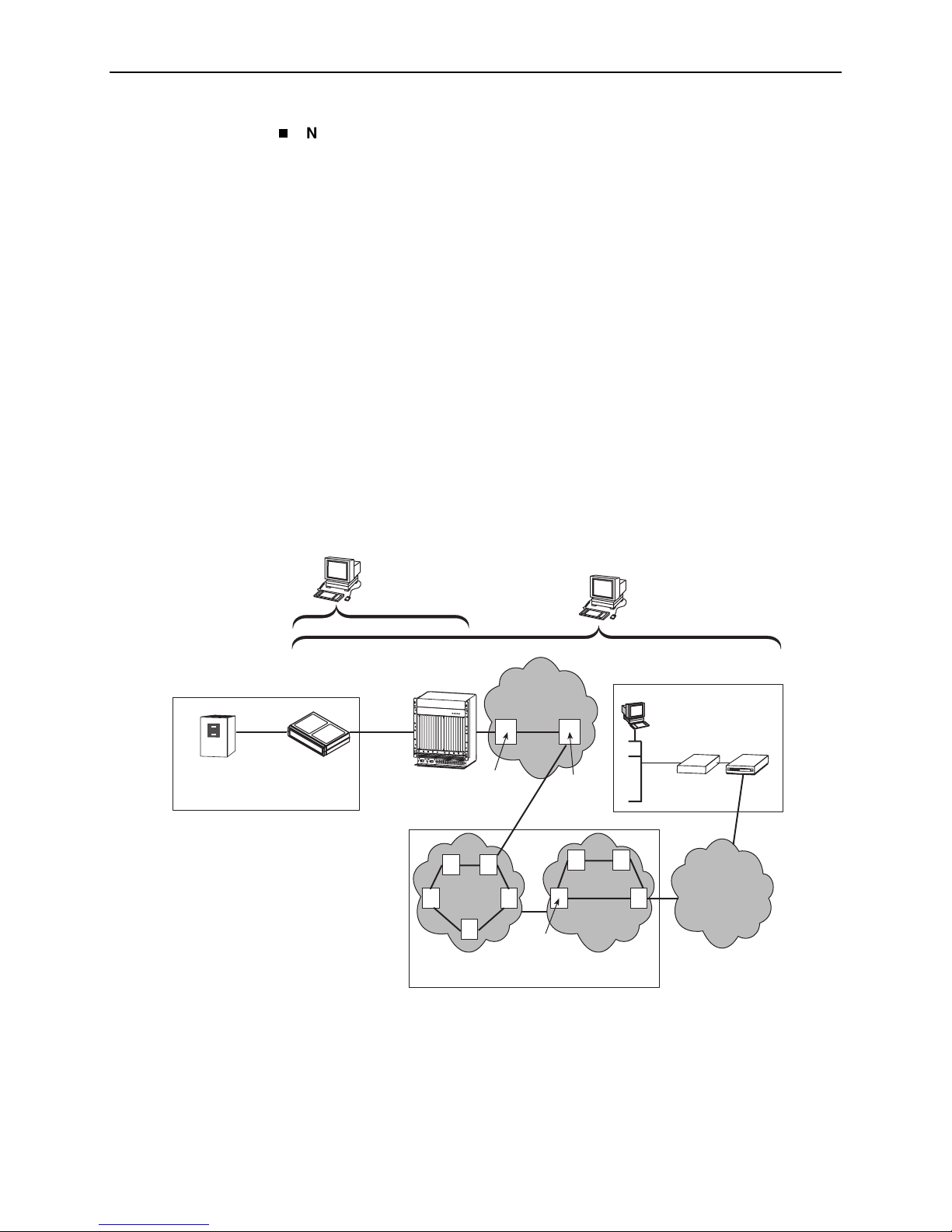
Network Configuration Examples
FrameSaver DSL devices can function in a variety of network configurations. The
following illustration shows a typical frame relay network configuration that
includes a FrameSaver DSL CSU/DSU.
OpenLane
NMS
Customer Premises –
Remote Site
Frame
Relay
Frame Relay
CPE
FrameSaver
xDSL Unit
Router/FRAD
DSL Provider's
Network
Operations
Center
DSL
Copper
Loop
POWE
R
ENTR
Y MO
D
U
LE
L
EFT
U
N
IT:
LI
N
E A
POWE
R
ENTR
Y
M
ODU
LE
RI
G
H
T UN
IT
:
L
I
N
E B
48V RTN
LEF
T UNI
T: LINE
A
R
I
G
HT
U
N
IT:
48V NEG
LI
N
E
B
48V RTN
48V NEG
W
A
R
N
I
N
G
!
P
O
W
E
R
M
U
S
T
B
E
D
I
S
C
O
N
N
E
C
T
E
D
A
T
T
H
B
E
E
S
F
O
O
U
R
R
E
C
R
E
E
M
O
V
I
N
G
O
R
I
N
S
W
T
A
A
L
R
L
I
N
N
I
G
N
T
G
H
!
I
S
P
O
P
W
W
E
R
R
E
M
N
T
U
R
S
Y
T
M
B
O
E
D
D
U
I
S
L
C
E
O
N
N
E
C
T
E
D
A
T
T
H
B
E
E
S
F
O
O
U
R
R
E
C
R
E
E
M
O
V
I
N
G
O
R
I
N
S
T
A
L
L
I
N
G
T
H
I
S
P
W
R
E
N
T
R
Y
M
O
D
U
L
E
DSLAM
P
O
W
E
R
BA
CLO
CK
S
ER
IAL
AC
A
M
CC
AL
AR
M
L
A
N
2
/W
AN
S
4
LO
T
6
8
A
10
B
SE
R
IAL
A
LAR
M
1
C
3
LO
CK
S
M
5
CM
7
9
B
Product-Related Documents
Frame Relay
A
L
A
R
M
S
F
a
n
M
a
j
o
r
M
i
n
o
r
12
1
4
1
6
1
8
1
1
1
3
1
5
17
Switch
AT M
OpenLane
NMS
DSL ATM
Access
Network
AT M
PVC
AT M
Switch
for upgrade information and
in
About This Guide
NSP's
Network
Operations
Center
Customer Premises –
HQ Site
DHCP
Server
FrameSaver
LAN
Endpoint
Router
for
.
9700-A2-GB20-20 December 2002 1-7
AT M
Switches
FR Network
FR
Switches
FR/ATM
IWF
Frame Relay NSP’s Network
TDM
Access
Network
01-16770-01
Page 22
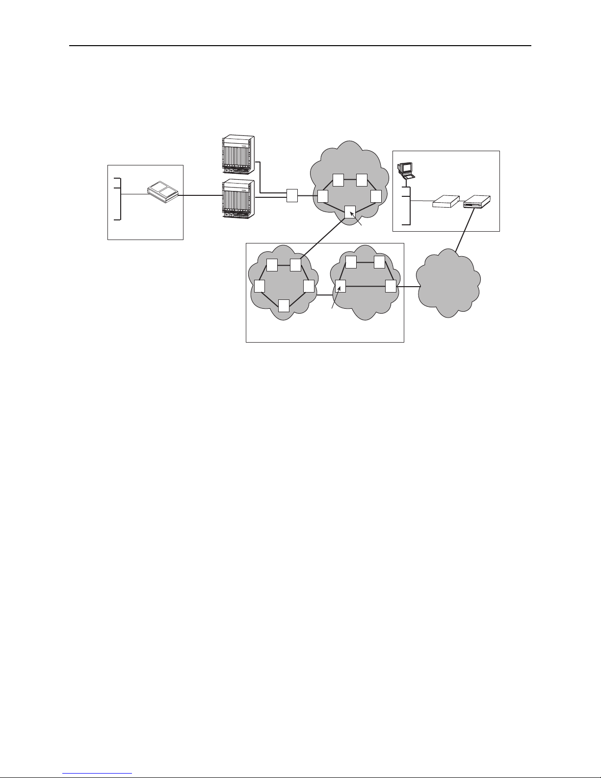
1. About FrameSaver DSL Devices
The illustration below shows a typical network configuration that includes a
FrameSaver DSL Router.
Customer Premises –
Remote Site
LAN
FrameSaver
xDSL Router
Endpoint
DSL
Copper
Loop
Central Office
P
O
W
E
R
A
L
A
R
M
S
BA
F
a
n
M
a
jo
r
M
in
o
r
P
O
W
E
R
E
N
T
R
Y
M
O
D
U
L
E
L
C
E
L
F
T
O
U
C
N
I
K
T
:
L
I
SE
N
E
P
A
O
R
W
IA
E
R
L
E
N
T
R
Y
A
M
C
O
D
U
L
E
R
I
G
H
T
U
N
I
T
:
L
I
N
A
E
B
48V RTN
L
E
M
F
T
CC
U
N
I
T
:
L
I
A
N
E
LA
A
R
M
L
A
N
2
/W
A
R
N
I
G
H
S
T
U
4
LO
N
48V NEG
I
T
:
T
L
I
N
E
B
48V RTN
6
8
A
1
0
1
2
48V NEG
1
4
1
6
1
8
W
A
R
N
I
N
G
!
P
O
W
ER
MU
S
T
BE
D
I
SCO
N
NECT
ED
A
T TH
E
B
E
S
FO
OU
R
R
E
CE
R
EM
O
V
I
N
G O
R
I
NS
W
T
AL
A
R
L
N
ING
I
N
TH
G
!
P
IS
O
PW
W
E
R
R
E
MU
NT
ST
RY
BE
M
O
DI
DU
S
CO
LE
N
NE
C
TE
D
A
T T
HE
BE
S
F
OUR
OR
E
CE
RE
M
OV
IN
G
OR
I
NS
T
A
LL
IN
G
TH
I
S
P
W
R
E
NT
R
Y
M
ODU
LE
B
S
E
R
IA
L
A
L
AR
M
1
C
3
L
O
C
K
SM
5
C
M
7
9
B
11
13 15
1
7
P
O
W
E
R
A
L
A
RM
S
A
B
F
a
n
M
a
j
o
r
M
i
n
o
r
P
O
W
E
R
E
N
T
R
Y
M
O
D
U
L
E
L
CLO
E
F
T
U
C
N
I
K
T
:
L
I
S
N
E
E
P
A
O
RI
W
E
AL
R
E
N
T
R
Y
A
M
C
O
D
U
L
E
R
I
G
H
T
U
N
I
T
:
L
I
N
A
E
B
48V RTN
L
E
M
F
T
CC
U
N
I
T
:
L
I
A
N
E
L
A
A
R
M
L
A
N
2
/W
A
R
N
I
G
H
SL
T
U
4
N
O
48V NEG
I
T
:
T
L
I
N
E
B
48V RTN
6
8
A
1
0
1
2
48V NEG
1
4
1
6
1
8
W
A
R
N
I
N
G
!
P
O
W
E
R
M
US
T
BE
D
IS
CON
NE
C
TE
D
A
T
TH
E
BE
SO
F
OR
U
RCE
E
RE
M
OV
I
NG
O
R
INS
W
T
A
A
LL
R
N
IN
I
N
G
G
TH
!
PO
I
S
P
W
W
ER
R
E
M
NT
UST
R
Y
B
MO
E
D
D
IS
UL
CO
E
N
NE
C
TE
D
A
T
TH
E S
BE
F
O
O
U
R
RCE
E
RE
M
O
VI
NG
O
R
IN
S
T
A
LL
I
N
G
TH
IS
P
WR
E
N
TR
Y
M
OD
U
LE
B
S
E
R
I
AL
AL
A
R
M
1
C
3
LO
C
K
SM
5
C
M
7
9
B
1
1
1
3
1
5
17
DSLAMs
Aggregation
Switch
(Optional)
AT M
NNI(s)
DSL
Access
Network
AT M
Services
Switches
AT M
Customer Premises –
HQ Site
DHCP
Server
FrameSaver
LAN
Endpoint
Router
Switches
Frame Relay NSP’s Network
ATM – Asynchronous Transfer Mode
DHCP – Dynamic Host Configuration Protocol
DSL – Digital Subscriber Line
FR – Frame Relay
HQ – Headquarters
AT M
FR Network
FR
Switches
FR/ATM
IWF
IWF – Interworking Function
LAN – Local Area Network
NSP – Network Service Provider
TDM – Time Division Multiplexer
TDM
Access
Network
01-16915-01
1-8 December 2002 9700-A2-GB20-20
Page 23

OpenLane SLM System
Paradyne’s OpenLane® Service Level Management (SLM) solution is an open,
standards-based, highly distributable system offering robust scalability and
flexibility. A Web browser-enabled user interface provides accessibility anytime,
anywhere.
Paradyne’s network management solution features support for diagnostics,
real-time performance monitoring, historical reporting, and detailed health and
status indicators for Paradyne’s SNMP-managed network access device families.
OpenLane Features
Some of the OpenLane system’s features include:
Easy-to-use Web browser-based user interface
Optional integration with HP OpenView
Device configuration through the Web interface
1. About FrameSaver DSL Devices
Real-time device health and status, diagnostics, and performance monitoring
Extensive Web-based diagnostics, including non-disruptive PVC loopback and
end-to-end connectivity testing
Real-time performance graphs and historical SLV graphs
Service level management historical reports, including:
— Frame Delivery Ratio Detail
— Frame Transfer Delay Detail
— Availability Detail
— Network Capacity and Throughput Detail
— PVC Tx Activity (by % CIR) Detail
— Protocol Distribution Detail
— Top 6 IP Communicator Distribution
— PVC Congestion Detail
— DTE Port Errors
— Network Port Errors
— Port Trend Analysis
— PVC Trend Analysis
— SLV Detail
Diagnostic troubleshooting tests, including end-to-end, connectivity, and
nondisruptive PVC, ATM, and frame relay loopbacks
Automatic SLV device and PVC discovery
Ability to reset FrameSaver DSL devices from the OpenLane system
Firmware download to a single device or an entire network
On-demand polling of FrameSaver devices
9700-A2-GB20-20 December 2002 1-9
Page 24

1. About FrameSaver DSL Devices
1-10 December 2002 9700-A2-GB20-20
Page 25

User and Command Line Interfaces,
and Basic Operation
This chapter explains how to access, use, and navigate the menu-driven user
interface and the router’s Command Line Interface (CLI ).
It includes the following:
Logging On
—
Ending a Session
Main Menu
Screen Work Areas
Navigating Menu-Driven User Interface Screens
on page 2-2
on page 2-4
on page 2-5
2
on page 2-6
—
Keyboard Keys
—
Function Keys
—
Selecting from a Menu
—
Switching Between Screen Areas
—
Selecting a Field for Input
Navigating the Router’s CLI
—
CLI Keyboard Keys
What appears on interface screens depends on:
Current configuration – How your network is currently configured.
Security access level – The security level set by the system administrator for
each user.
Data selection criteria – What you entered in previous screens.
on page 2-9
9700-A2-GB20-20 December 2002 2-1
Page 26

2. User and Command Line Interfaces, and Basic Operation
Logging On
Start a session using one of the following methods:
Telnet session via:
— An in-band management channel through the frame relay network (frame
relay network service provider).
— An in-band management channel through the ATM network (DSL
provider).
— A local in-band management channel configured on the DTE port between
the FrameSaver DSL CSU/DSU and a router (V.35 units only).
— An Ethernet LAN port.
Dial-in connection using an external modem.
Direct terminal connection over the COM port.
If no security was set up or security was disabled, the Main Menu screen appears
(see the example in
Main Menu
on page 2-4). You can begin your session.
If security was set up and is enabled, you are prompted for a login. Enter your login
ID and password.
If your login was . . . Then the . . .
Valid Main Menu appears. Begin your session.
NOTE: If your login is valid, but access is denied, there are
two currently active sessions.
Invalid Message, Invalid Password, appears on line 24, and
the Login screen is redisplayed.
After three unsuccessful attempts:
A Telnet session is closed.
The User Interface Idle screen appears for a directly
connected terminal or modem.
An external modem is disconnected.
An SNMP trap is generated.
Access is denied.
See your system administrator to verify your login (Login
ID/Password combination).
When the user interface has been idle, the device times out and the session is
automatically ended; the screen goes blank. Press Enter to reactivate the
interface.
2-2 December 2002 9700-A2-GB20-20
Page 27

2. User and Command Line Interfaces, and Basic Operation
Procedure
To log in when security is being enforced:
1. Type your assigned Login ID and press Enter.
2. Type your Password and press Enter.
— Valid characters – All printable ASCII characters
— Number of characters – Up to 10 characters can be entered in the
Login ID and Password fields
— Case-sensitive – Yes
An asterisk ( *) appears in the password field for each character entered.
FrameSaver devices support two sessions simultaneously. If two sessions are
currently active, wait and try again.
If two sessions are currently active and you are attempting to access the unit
through Telnet, the local Telnet server process returns a Connection
refused: message at the bottom of the screen.
Ending a Session
If two sessions are currently active and you are attempting to access the unit
over the COM port (using a terminal or external modem, not via Telnet), the
User Interface Already In Use screen is displayed. In addition, the type of
connection (Telnet Connection or Direct COM Port Connection) for each
current user is identified, along with the user’s login ID.
When the user interface has been idle, the unit times out and the session is
automatically ended; the screen goes blank. Press Enter to reactivate the
interface. See Chapter 6,
Security and Logins
, to set up and administer logins.
Procedure
To end the session:
1. Press Ctrl-a to switch to the function keys area of the screen.
2. Type e (E
— For a terminal-connected to the COM port, the session is ended.
— For a modem connected to the COM port, the session is ended and the
— For a Telnet connection, the session is closed and, if no other Telnet or
xit) and press Enter.
modem is disconnected.
FTP session is occurring over the connection, the modem is
disconnected.
If ending a session from a Configuration menu, see
in Chapter 3,
9700-A2-GB20-20 December 2002 2-3
Configuration Procedures
Saving Configuration Options
.
Page 28

2. User and Command Line Interfaces, and Basic Operation
Main Menu
Entry to all FrameSaver device tasks begins at the Main Menu, which provides
access to several menus. The Access Level appears at the top of the screen
when security has been set up.
main Access Level: 1 9783-RtrSLV
Device Name: Node A 2/26/2001 02:01
MAIN MENU
Status
Test
Configuration
Control
Easy Install
------------------------------------------------------------------------------Ctrl-a to access these functions, Shift-r to access the Router's CLI Exit
Shift-r to access the Router's CLI appears only for the FrameSaver
DSL Router. See
Navigating the Router’s CLI
on page 2-9 for additional
information.
Select . . . To . . .
Status View diagnostic tests, interfaces, PVC connections, statistics,
LEDs, and FrameSaver unit identity information (except the
router’s CLI).
Test Select, start, and stop tests for the FrameSaver unit’s interfaces
(except the router’s CLI ).
Configuration Display and edit the configuration option settings (except the
router’s CLI).
Control Control the menu-driven user interface device naming, login
administration (except the router’s CLI), clock setting, and
software releases selection. You can also initiate a power-on reset
of the FrameSaver unit.
Easy Install Perform a quick installation.
See Appendix A,
structures.
2-4 December 2002 9700-A2-GB20-20
Menu Hierarchy
, for a pictorial view of FrameSaver device menu
Page 29
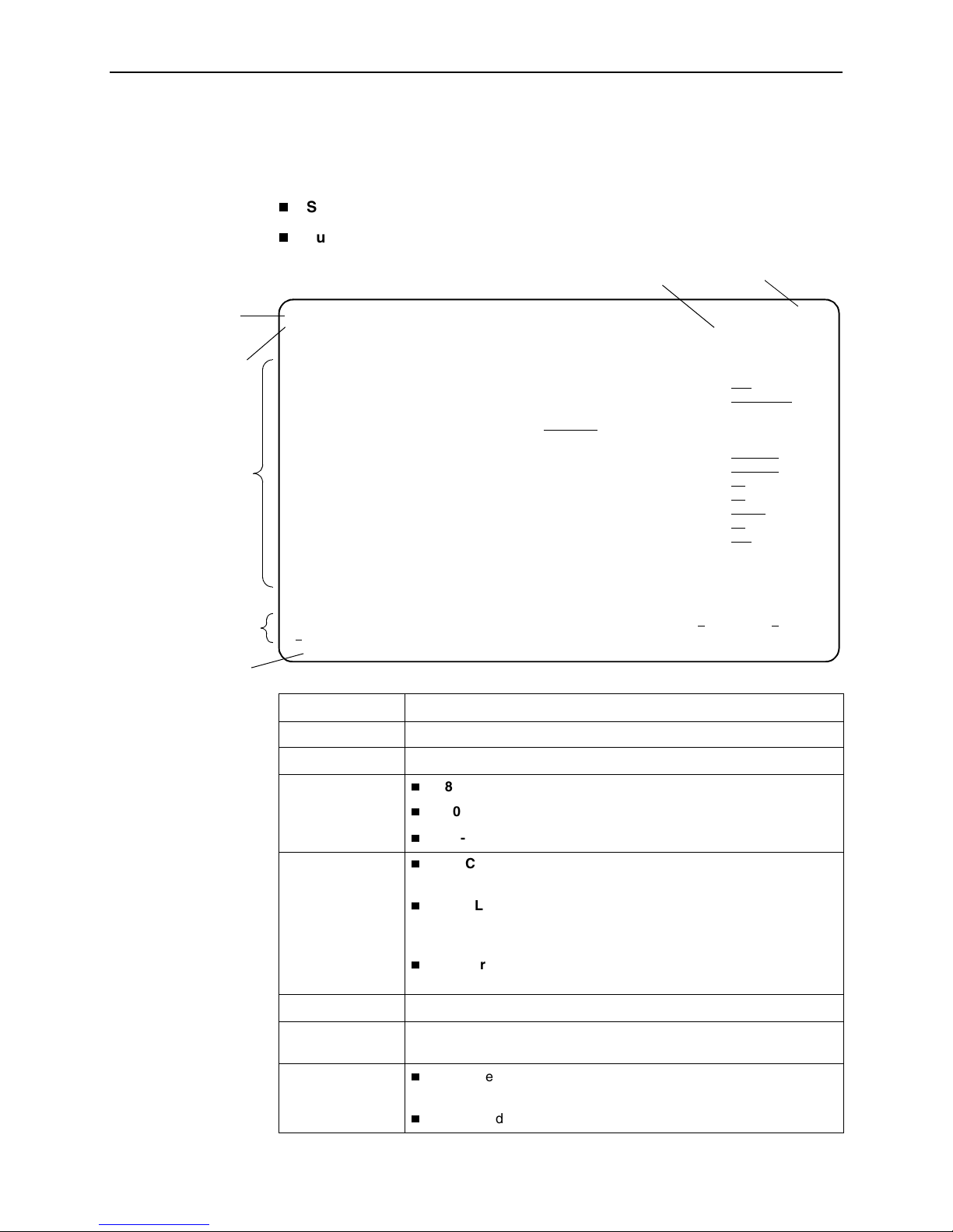
Screen Work Areas
There are two user work areas:
2. User and Command Line Interfaces, and Basic Operation
Screen area – Where you input information or information is displayed.
Function keys area – Where you perform specific screen functions.
Menu Path
Device Name
Screen Area
Function Keys Area
Message Area
Date and Time
main/config/system/slv 9783-C-SLV
Device Name: Node A 05/13/2002 23:32
SERVICE LEVEL VERIFICATION SYSTEM OPTIONS
SLV Sample Interval (secs): 60
SLV Synchronization Role: Tributary
SLV Type: Standard
SLV Delivery Ratio: Disable
DLCI Down on SLV Timeout: Enable
SLV Timeout Error Event Threshold: 3
SLV Timeout Clearing Event Threshold: 1
SLV Round Trip Latency Error Threshold (ms): 10000
SLV Latency Clearing Event Threshold: 2
SLV Packet Size (bytes): 64
------------------------------------------------------------------------------Ctrl-a to access these functions, ESC for previous menu MainMenu Exit
Save
Model Number
Screen Format Description
Menu Path Menu selections made to reach the current screen.
Device Name Customer-assigned name for the FrameSaver device.
Model Number:
Feature Set 1
Model Number:
Advanced SLM
Feature Set
9783-C – Central site CSU/DSU that supports 64 PVCs.
9720, 9783, 9788 – Remote site CSU/DSU that supports 8 PVCs.
9783-Rtr, 9788-Rtr – Router that supports 8 PVCs.
9783-C-SLV – Central site CSU/DSU that supports 64 PVCs and
has the Advanced SLM Feature Set installed.
9720-SLV, 9783-SLV, 9788-SLV – Remote site CSU/DSU that
supports 8 PVCs and has the Advanced SLM Feature Set
installed.
9783-RtrSLV, 9788-RtrSLV – Router that supports 8 PVCs and
has the Advanced SLM Feature Set installed.
Screen Area Fields for configuring and monitoring the FrameSaver device.
Function Keys
Area
Message Area
Specific functions that can be performed by pressing a specified key,
then pressing Enter.
System-related information and valid settings for input fields in the
lower left corner.
System and Test Status messages in the lower right corner.
9700-A2-GB20-20 December 2002 2-5
Page 30

2. User and Command Line Interfaces, and Basic Operation
Navigating Menu-Driven User Interface Screens
You can navigate the menu-driven user interface screens by using:
Keyboard keys.
Function keys to switch between the two screen work areas.
Keyboard Keys
For CLI navigation, see
Navigating the Router’s CLI
on page 2-9.
Use the following keyboard keys to navigate within the screen area.
Press . . . To . . .
Esc Return to the previous screen.
Backspace Move cursor one position to the left or to the last
character of the previous field.
Spacebar Select the next valid value for the field.
Delete (Del) Delete character that the cursor is on.
Ctrl-a Move cursor between the screen area and the
screen function keys area.
Shift-r Access the router’s Command Line Interface
(CLI).
Ctrl-l Redraw the screen display, clearing information
typed in but not yet entered.
Up Arrow or Ctrl-u Move cursor up one field within a column on the
same screen.
Down Arrow or Ctrl-d Move cursor down one field within a column on
Right Arrow or Ctrl-f Move cursor one character to the right if in edit
Right Arrow (on same screen row), or
Tab (on any screen row)
Left Arrow or Ctrl-b Move cursor one character to the left if in edit
Left Arrow (on same screen row), or
Ctrl-k
Enter (Return)
2-6 December 2002 9700-A2-GB20-20
the same screen.
mode.
Move cursor to the next field.
mode.
Move cursor to the previous field.
Accept default or displayed entry, or after
entering data.
Display valid options on the last row of the
screen.
Page 31

Function Keys
2. User and Command Line Interfaces, and Basic Operation
All function keys located in the lower part of the screen (see the example in
Work Areas
on page 2-5) operate the same way throughout the screens. They are
Screen
not case-sensitive, so upper- or lowercase letters can be used interchangeably.
For the screen
Select . . .
M or m MainMenu Return to the Main Menu screen.
E or e E
N or n N
O or o Modify Change existing data.
L or l Del
S or s S
R or r Refresh Update screen with current information.
C or c C
function . . . And press Enter to . . .
xit Terminate the menu-driven user interface session.
ew Enter new data.
ete Delete data.
ave Save information.
lrStats Clear network performance statistics and refresh the
screen. Select the following functions:
ClrSLV&DLCIStats for clearing SLV and DLCI
statistics.
ClrLinkStats for clearing frame relay link statistics.
ClrStats for clearing Ethernet interface statistics.
Selecting from a Menu
U or u PgUp Display the previous page.
D or d PgD
n Display the next page.
Procedure
To select from a menu:
1. Tab or press the down (
selection, or press the up (
menu list.
Each menu selection is highlighted as you press the key to move the cursor
from position to position.
2. Press Enter. The selected menu or screen appears.
To return to a previous screen, press the Esc (Escape) key until you reach the
desired screen.
↓
) arrow key to position the cursor on a menu
↑
) arrow key to move the cursor to the bottom of the
9700-A2-GB20-20 December 2002 2-7
Page 32

2. User and Command Line Interfaces, and Basic Operation
Switching Between Screen Areas
Use Ctrl-a to switch between screen areas (see the example in
Areas
Procedure
To switch to the function keys area from the screen area:
1. Press Ctrl-a.
2. Select either the function’s underlined character or Tab to the desired function
3. Press Enter. The function is performed as shown in
To return to the screen area, press Ctrl-a again.
Selecting a Field for Input
Press the Tab or right arrow key to move the cursor from one field to another. The
current setting or value appears to the right of the field.
You can enter information in up to four ways. Select the field, then:
Screen Work
on page 2-5).
key.
Function Keys
on
page 2-7.
If a field is blank and the Message area displays valid selections, press the
spacebar; the first valid setting for the field appears. Continue pressing the
spacebar to scroll through other possible settings.
Manually type in the field value or command. For example, the Device Name
field on the System Information screen is initially blank. Type a name into the
input area next to Device Name:
Device Name: MyDeviceName
Manually type in the first letter(s) of a field value or command, using the unit’s
character-matching feature. Type as many characters as are required to have
the software distinguish one option from another. For example, when
configuring the Network ATM option FRF.8 Encapsulation Mode, the default
option Transparent is at first displayed; typing transl causes the option
Translational to be displayed.
Switch to the function keys area and select or enter a designated function key.
For example, S
ave is one of the available commands in the function keys area
of configuration screens. To save a configuration option change, press Ctrl-A
and s (or S). The s key is the designated function key for S
ave.
2-8 December 2002 9700-A2-GB20-20
Page 33

Navigating the Router’s CLI
Access the FrameSaver DSL Router’s Command Line Interface by pressing the
Shift-r function key from the Main Menu. There is no need to press Ctrl-a first to
access the function keys area of the screen.
Once the CLI is accessed, you can use keyboard keys to navigate within the
interface. Using the router’s CLI, you can display and edit router configuration
settings, view router status, and access router tests.
For details of all CLI commands and the conventions used when entering
commands, see Appendix C,
For a summary of abbreviated (minimal) command entries and their default
settings, see Appendix D,
CLI Keyboard Keys
Use the following keyboard keys to navigate within the router’s CLI. Most terminal
emulation programs use these same keys.
2. User and Command Line Interfaces, and Basic Operation
Router CLI Commands, Codes, and Designations.
Router Command Line Summaries and Shortcuts.
Press . . . To . . .
Enter (Return) Accept the current command line input.
Ctrl-c
Ctrl-z Exit Configuration mode and returns to Standard mode. A prompt
Backspace Erase the character to the left of the cursor.
Delete Erase the character the cursor is on.
Down Arrow Recall command line history buffer with the most recent
Up Arrow Scroll to the last valid command for editing.
Right Arrow Move the cursor one position to the right.
Left Arrow Move the cursor one position to the left.
q
(or any key but
Spacebar or
Enter/Return)
Clear the current command line entry.
Abort a command line prompt without answering.
Exit a command in progress.
appears to save any unsaved changes.
command displaying first. Buffer contains ten lines of history.
Abort a Move display and return to the command line prompt.
9700-A2-GB20-20 December 2002 2-9
Page 34

2. User and Command Line Interfaces, and Basic Operation
2-10 December 2002 9700-A2-GB20-20
Page 35

Configuration Procedures
While it is easiest to configure FrameSaver devices using the OpenLane SLM
system, you can configure the FrameSaver DSL CSU/DSUs and routers using the
menu-driven user interface.
This chapter includes the following:
Basic Configuration From the User Interface
—
Configuration Option Areas
—
Accessing and Displaying Configuration Options
—
Changing Configuration Options
3
on page 3-2
—
Saving Configuration Options
9700-A2-GB20-20 December 2002 3-1
Page 36

3. Configuration Procedures
Basic Configuration From the User Interface
Configuration option settings determine how the FrameSaver DSL device
operates. Use the unit’s Configuration Edit/Display menu to display or change
configuration option settings.
Configuration Edit/Display Menu
main/config 9783-C-SLV
Device Name: Node A 2/26/2001 03:01
CONFIGURATION EDIT/DISPLAY
System
Network
Data Ports
PVC Connections
Management and Communication
-------------------------------------------------------------------------------Ctrl-a to access these functions, ESC for previous menu MainMenu Exit
Save
3-2 December 2002 9700-A2-GB20-20
Page 37

Configuration Option Areas
The FrameSaver device arrives with configured factory default settings, which are
located in the Factory Default Configuration option area. You can find the default
settings for configuration options in the:
Configuration Option Tables
FrameSaver DSL CSU/DSU, Models 9783 and 9788, Quick Reference
FrameSaver DSL Router, Models 9783 and 9788, Quick Reference
If the factory default settings do not support your network’s configuration, you can
customize the configuration options to better suit your application.
Four configuration option storage areas are available.
Configuration Option Area Description
Current Configuration The currently active set of configuration options.
Customer Configuration 1 An alternate set of configuration options that the
3. Configuration Procedures
in Chapter 4,
customer can set up and store for future use.
Configuration Options
, or
Scratchpad Configuration An alternate configuration area for temporary use. The
Scratchpad configuration is reset to the factory default
settings when the unit is powered off and on.
Default Factory Configuration A read-only configuration area containing the factory
default set of configuration options.
You can load and edit default factory configuration
settings, but you can save changes only to the Current,
Customer, or Scratchpad configuration option areas.
The Current, Customer, and Scratchpad configuration
option areas are initially identical with the Default Factory
Configuration.
9700-A2-GB20-20 December 2002 3-3
Page 38

3. Configuration Procedures
Accessing and Displaying Configuration Options
To access and display configuration options, load a configuration option set into
the edit area.
Procedure
To load a set of configuration options for editing:
1. From the Main Menu, press the down arrow key until the cursor is on
Configuration.
2. Press Enter to display the Configuration menu. The Load Configuration
From: menu appears.
NOTE:
Loading a configuration with many DLCIs from a unit’s Customer or
Scratchpad configuration option area may take time. Allow a minute or
more for the file to be loaded.
3. Select the configuration option area from which you want to load configuration
options (Current Configuration, Customer Configuration, Scratchpad
Configuration, or Default Factory Configuration) and press Enter.
The selected set of configuration options is loaded into the configuration edit
area and the Configuration Edit/Display menu appears.
This sequence of steps is shown in this guide as the menu selection sequence:
Main Menu→Configuration
3-4 December 2002 9700-A2-GB20-20
Page 39

Changing Configuration Options
When security has been set up, only Security Access Level 1 users can change
configuration options. See Chapter 6,
information.
Procedure
To change configuration option settings:
1. From the Configuration Edit/Display menu, select a set of configuration options
and press Enter.
For example:
Configuration→PVC Connections
2. Make appropriate changes to the configuration option setting(s). For additional
information regarding the user interface, see Chapter 2,
Line Interfaces, and Basic Operation.
When creating new PVC connections or management PVCs, some
configuration options will be blank. For a valid setting to appear, Tab to the
configuration option and press the spacebar.
Security and Logins,
3. Configuration Procedures
for additional
User and Command
3. Repeat Steps 1 and 2 until all changes are complete.
ave your changes.
4. S
Saving Configuration Options
When changing configuration option settings, you must Save the changes before
they will take effect.
Procedure
To save configuration option changes:
1. Press Ctrl-a to switch to the function key area at the bottom of the screen.
2. Type s or S to select the S
The Save Configuration To: screen appears.
NOTE:
If you try to exit the Configuration menu without saving changes, a Save
Configuration screen appears requiring a Yes or No response.
— If you select N
ave function and press Enter.
o, the Main Menu screen reappears and the changes
are not saved.
3. Select the configuration option area to which you want to save your changes
(normally the Current Configuration) and press Enter.
When the Save is complete, Command Complete appears in the message
area at the bottom of the screen.
9700-A2-GB20-20 December 2002 3-5
— If you select Y
es, the Save Configuration To: screen appears.
Page 40

3. Configuration Procedures
For the router, saving also updates the router’s configuration database, adding
newly configured DLCIs or subnets that do not yet exist in the router database.
NOTE:
There are other methods of changing configurations, like SNMP and
Auto-Configuration. Since multiple sessions can be active at the same
time, the last change made overwrites any previous or current changes
being made. For instance:
— Saving your configuration changes would cause configuration
changes made via another method to be lost.
— If you are making changes and someone else makes changes and
saves them, your changes would be lost.
3-6 December 2002 9700-A2-GB20-20
Page 41

Configuration Options
This chapter describes all the configuration options available on the FrameSaver
DSL devices. They can be modifed using the user interface or OpenLane SLM:
Using the Easy Install Feature
Entering System Information and Setting the System Clock
Configuration Option Tables
Configuring the Overall System
—
Configuring Frame Relay and LMI for the CSU/DSU
—
Configuring Class of Service Definitions
4
on page 4-3
on page 4-8
on page 4-9
on page 4-10
—
Configuring Service Level Verification Options
—
Configuring General System Options
Configuring Network Interfaces
Configuring the Network Physical Interface
—
—
Configuring Frame Relay for the Network Interface
—
Configuring Circuit Records for the Network Interface (9783, 9788)
—
Configuring ATM for the Network Interface (9783, 9788)
Configuring the User Data or Virtual Router Port
—
Configuring the CSU/DSU’s Data Port Physical Interface
—
Configuring Frame Relay on the CSU/DSU’s Data Port
—
Configuring DLCI Records
Configuring PVC Connections
Configuring the IP Path List
Setting Up Management and Communication
—
Configuring Node IP Information
on page 4-20
on page 4-35
on page 4-37
on page 4-28
on page 4-38
—
—
9700-A2-GB20-20 December 2002 4-1
Configuring Management PVCs
Configuring General SNMP Management
Page 42

4. Configuration Options
—
Configuring Telnet and/or FTP Sessions
—
Configuring SNMP NMS Security
—
Configuring SNMP Traps
—
Configuring Ethernet Management
—
Configuring the Communication Port
—
Configuring the COM Port to Support an External Modem
Default settings for some parameters may be different than shown here for models
with customer-specific factory settings.
See Chapter 5,
Configuring the FrameSaver DSL Router
configuration information when setting up the router.
, for additional
4-2 December 2002 9700-A2-GB20-20
Page 43

Using the Easy Install Feature
An Easy Install screen is provided for custom configurations, but is not required for
normal installation.
The FrameSaver Easy Install feature provides minimal configuration. Once the
installation and configuration are complete, the NOC can complete unit
configuration and verify the setup.
Main Menu→Easy Install
Easy Install Screen
main/easy_install 978x-xxxxx
Device Name: Node A 09/06/2002 04:02
EASY INSTALL
(9783:) DSLAM Type: Paradyne
Node IP Address: 000.000.000.000 Clear
Node Subnet Mask: 000.000.000.000 Clear
TS Access: VPI,VCI 0 , 35
4. Configuration Options
Create a Dedicated Network Management Link
Ethernet Management Options Screen
(9720:) Network 1 Operating Rate (Kbps) AutoRate
(9783/9788:) Network 1 DSL Line Rate (Kbps) AutoRate
(9788 DSU:) Port-1 Port Type: V.35
(9783/9788:) Network 1 FRF.8 Encapsulation Mode Transparent
-------------------------------------------------------------------------------Ctrl-a to access these functions, ESC for previous menu MainMenu Exit
Save
To access the device:
For non-managed networks: Use the TS Access DLCI to ping the unit five
times within five seconds.
For managed networks: Use the Dedicated Network Management Link that
is created.
Table 4-1, Easy Install Configuration Options, describes the entries on the Easy
Install screen.
9700-A2-GB20-20 December 2002 4-3
Page 44

4. Configuration Options
Table 4-1. Easy Install Configuration Options (1 of 4)
DSLAM Type (9783)
Possible Settings: Paradyne, Alcatel (NewBridge), PairGain, Nokia
Default Setting: Paradyne
Ensures interoperability with non-Paradyne DSLAMs, not just the Hotwire GranDSLAM.
This option is only available from the Easy Install screen.
NOTES:
– The default is set before the unit is shipped, based upon the CLEC customer
ordering the unit. If you change the default, you must S
effect, which will reset the unit.
– When the default is changed, the default settings for other configuration options
change. See
on page 4-21, and
Paradyne – The FrameSaver device is used with a Hotwire GranDSLAM.
Alcatel (NewBridge) – The FrameSaver device is used with Alcatel’s NewBridge DSLAM.
PairGain – The FrameSaver device is used with PairGain’s DSLAM.
Nokia – The FrameSaver device is used with Nokia’s DSLAM.
Network 1 DSL Line Rate (9783)
Cell Payload Scrambling
on page 4-27 for more information.
on page 4-6,
ave the change for it to take
DSL Line Rate (Kbps)
Node IP Address
Possible Settings: 001.000.000.000–126.255.255.255,
128.000.000.000–223.255.255.255, Clear
Default Setting: Clear (000.000.000.000)
Specifies the IP address needed to access the node. Since an IP address is not bound to
a particular port, it can be used for remote access via a management PVC.
001.000.000.000 – 223.255.255.255 – Shows the IP address for the node, which can be
viewed or edited. The first octet of the address cannot be decimal 0 or 127, or greater than
223.
Clear – Fills the node IP address with zeros.
Node Subnet Mask
Possible Settings: 000.000.000.000 – 255.255.255.255, Clear
Default Setting: 000.000.000.000
Specifies the IP address subnet mask that is needed to access the node. Since the
subnet mask is not bound to a particular port, it can be used with the Node IP address for
remote access via a management PVC.
000.000.000.000 – 255.255.255.255 – Shows the subnet mask for the node, which can be
viewed or edited.
Clear – Fills the node subnet mask with zeros. When the node’s subnet mask is all zeros,
the IP protocol creates a default subnet mask based upon the IP address class
(Class A: 255.000.000.000, Class B: 255.255.000.000, or Class C: 255.255.255.000).
4-4 December 2002 9700-A2-GB20-20
Page 45

4. Configuration Options
Table 4-1. Easy Install Configuration Options (2 of 4)
TS Access
Possible Settings: None, DLCI, VPI,VCI, DLCI_on_VPI,VCI
Default Setting: [Depends on model]
Specifies the type of Virtual Circuit (VC) by which special troubleshooting (TS) access is
provided to service providers.
None – No special troubleshooting link is defined.
DLCI – Allows the user to select a frame relay DLCI to be designated for special
troubleshooting access.
VPI,VCI – Specifies an ATM VC on a specific ATM VPI,VCI for TS access. It specifies the
VPI and VCI on the network interface for service provider troubleshooting. ATM data is
presumed to be encapsulated according to RFC 1483 (see
Encapsulation Mode (9783 and 9788)
management path between the FrameSaver device and the DSLAM. The VPI and VCI are
entered separately.
– VPI range is 0–15.
– VCI range is 32–255.
DLCI_on_VPI,VCI – Specifies a frame relay DLCI VC on a specific ATM VPI,VCI for
TS access. DLCI range is 16–1007. ATM data is presumed to be encapsulated according
to RFC 1490 (see
Network 1 FRF.8 Encapsulation Mode (9783 and 9788)
on page 4-7). VPI 0,VCI 35 is the default
Network 1 FRF.8
on page 4-7).
Create a Dedicated Network Management Link
Possible Settings: 16 – 1007
Default Setting: Initially blank
Enter a DLCI number and VPI,VCI for a dedicated network management PVC.
NOTE: With the cursor on the Create a Dedicated Network Management Link field,
press Enter. The Which DLCI would you like to Create a Dedicated
Frame Relay Management PVC on? prompt appears. If the DLCI entered is over
an ATM link, or Port-1 for the CSU/DSU. Prompts for VPI and VCI also appear.
16 – 1007 – Specifies the DLCI number be used.
Ethernet Management Options Screen
Provides a link to the Ethernet Management Options Screen. Press Enter and the screen
appears (see
Ethernet options, press the Esc key to return to the Easy Install screen.
Network 1 DSL Line Rate Mode
Possible Settings: Hunt (9783), AutoRate, Fixed
Default Setting: AutoRate
Specifies the mode to be used for rate selection.
Hunt – (9783 only.) The unit attempts to train at rate specified by Network 1 DSL Line
Rate. If that fails, the unit attempts to train at the next higher rate, and, if unsuccessful,
cycles through all the rates until training is successful or the unit is reset.
AutoRate – The unit automatically detects the line rate from the network interface.
Fixed – The unit uses the line rate specified by Network 1 DSL Line Rate.
Configuring Ethernet Management
on page 4-57.) After configuring
9700-A2-GB20-20 December 2002 4-5
Page 46

4. Configuration Options
Table 4-1. Easy Install Configuration Options (3 of 4)
Network 1 DSL Line Rate (9783)
Possible Settings:
If DSLAM Type is set to Paradyne, or if DSLAM Type is set to Nokia and Network 1
–
DSL Line Rate Mode is set to Fixed:
768, 784, 1024, 1152, 1168, 1536, 1552, 2320
–
If DSLAM Type is set to Alcatel (NewBridge):
– If DSLAM Type is set to Nokia and Network 1 DSL Line Rate Mode is set to Hunt:
192, 384, 768, 1152, 1536
If DSLAM Type is set to PairGain:
–
768, 784, 1024, 1152, 1168, 1536, 1552, 2320
Default Setting:
– If DSLAM Type is set to Alcatel (NewBridge) and Network 1 DSL Line Rate Mode is
set to Hunt:
208
– If DSLAM Type is set to Nokia and Network 1 DSL Line Rate Mode is set to Hunt:
384
–
If DSLAM Type is set to PairGain and Network 1 DSL Line Rate Mode set to Fixed:
784
–
(If DSLAM Type is set to Paradyne, Network 1 DSL Line Rate Mode is set to
AutoRate and Network 1 DSL Line Rate does not appear)
144, 192, 208, 256, 272, 384, 400, 512, 528,
208, 400, 784, 1168, 1552, 2320
144, 192, 208, 256, 272, 384, 400, 512, 528,
Determines whether the rate on the DSL interface is set to a specific value or
automatically detected using the Conexant AutoBaud algorithm.
144 – 2320 – Sets the DSL line rate in kbps.
Network 1 DSL Line Rate (9788)
Possible Settings:
If PSD Mask is Symmetric:
–
840, 904, 968, 1032, 1096, 1160, 1224, 1288, 1352, 1416, 1480, 1544, 1552, 1608,
1672, 1736, 1800, 1864, 1928, 1992, 2056, 2120, 2184, 2248, 2312
–
If PSD Mask is Asymmetric and Region Setting is Annex A:
If PSD Mask is Asymmetric and Region Setting is Annex B:
–
Default Setting: [None]
Determines the rate on the DSL network interface. Valid rates, and the rates presented on
the screen, depend on the values of Region Setting and PSD Mask on the Network
Physical Interface Options screen. If a change to another configuration option renders the
selected DSL Line Rate invalid, the line rate is set to AutoRate.
Display Conditions
Rate Mode is set to AutoRate.
200 – 2312 – The DSL line rate is set to the specified rate in kbps.
Network 1 Operating Rate (9720)
Possible Settings: AutoRate, 64, 128, 144
Default Setting: AutoRate
– Network 1 DSL Line Rate does not appear if Network 1 DSL Line
200, 264, 328, 392, 456, 520, 584, 648, 712, 776, 784,
776, 784, 1544, 1552
2056, 2312
Determines the rate on the IDSL network interface.
AutoRate – The unit automatically detects the line rate from the network interface.
64, 128, 144 – The IDSL line rate is set to the specified rate in kbps.
4-6 December 2002 9700-A2-GB20-20
Page 47

4. Configuration Options
Table 4-1. Easy Install Configuration Options (4 of 4)
Network 1 Channel (9720)
Possible Settings: B1, B2
Default Setting: B1
Specifies the B channel used for data transfer when the line rate is 64 kbps.
Display Conditions
is set to 64.
B1 – The B1 channel is used for data transfer.
B2 – The B2 channel is used for data transfer.
Port-1 Port Type (9788 CSU/DSU)
Possible Settings: E530, V.35, X.21
Default Setting: V. 3 5
Specifies the port type of the data port.
E530 – The port is configured as an EIA-530-A-compatible DCE. An EIA-530-Acompatible DTE may be directly connected to the DB25 connector for the port.
V. 3 5 – The port is configured as a V.35-compatible DCE. A V.35-compatible DTE may be
connected to the port using a DB25-to-MS34 adapter.
X.21 – The port is configured as an X.21-compatible DCE. An X.21-compatible DTE may
be connected to the port using a DB25-to-DB15 adapter.
– Network 1 Channel appears only when Network 1 Operating Rate
Network 1 FRF.8 Encapsulation Mode (9783 and 9788)
Possible Settings: Translational, Transparent
Default Setting: Transparent
Specifies the type of FRF.8 upper-layer protocol encapsulation used on the link for each
pair of interoperable Frame Relay and ATM PVCs.
Translational – Encapsulated data is translated (RFC 1490 to RFC 1483). FrameSaver
multiplexing and SLV communications are not supported in this mode.
Transparent – Encapsulated data is forwarded without being translated.
9700-A2-GB20-20 December 2002 4-7
Page 48

4. Configuration Options
Entering System Information and Setting the System Clock
Select System Information to set up or display the general SNMP name for the
unit, the location, a contact for the unit, and set the system clock.
Main Menu→Control→System Information
The following information is available. Save any entries or changes.
If the selection is . . . Enter the . . .
Device Name Unique name to identify the device (up to 20 characters).
System Name SNMP system name (up to 255 characters).
System Location System’s physical location (up to 255 characters).
System Contact System person name and how to contact (up to 255 characters).
ATM Location ID Identification of the ATM location for the system. The ID must be
entered as 16 one-byte values, each conveyed as two
hexadecimal characters, delimited by colons. When Clear is
selected, all octets are filled with 6A (for example,
6A:6A:6A:6A...), which is the factory default and an invalid value.
The values are restricted.
The first byte must be 01, 02, 03, FF, or 6A.
If the first octet is FF, the octets 2–16 must also be FF.
If the first octet is 6A, the octets 2–16 must also be 6A.
Date Current date in the month/day/year format (mm/dd/yyyy).
Time Current time in
NOTE:
To clear existing information, place the cursor in the Clear field (Tab to the
Clear field) and press Enter.
Changing the Operating Mode
The FrameSaver unit can be connected to another FrameSaver unit without a
frame relay switch between them. This is called back-to-back mode and can be
used for demonstrations or for a point-to-point configuration over a leased line.
To change the operating mode, select Change Operating Mode from the Control
menu:
Main Menu→Control→Change Operating Mode
On the ensuing screen, select Back-to-Back Operation or Standard Operation.
Standard Operation is the default mode.
the hours:minutes:seconds format (hh:mm:ss).
4-8 December 2002 9700-A2-GB20-20
Page 49

Configuration Option Tables
Configuration option descriptions contained in this chapter are in menu order, even
though this may not be the order in which they are accessed when configuring the
unit.
The following configuration option tables are included:
Table 4-2, CSU/DSU Frame Relay and LMI Options
Table 4-3, Class of Service Definitions
Table 4-4, Code Point Definitions
Table 4-5, Service Level Verification Options
Table 4-6, General Options
Table 4-7, Network Physical Interface Options (9720)
Table 4-9, Network Physical Interface Options (9788)
Table 4-10, Network Frame Relay Options
4. Configuration Options
Table 4-11, Circuit Records Options
Table 4-12, Network ATM Options
Table 4-13, CSU/DSU Data Port Physical Interface Options
Table 4-14, CSU/DSU Frame Relay Options
Table 4-15, DLCI Records
Table 4-16, PVC Connections
Table 4-17, IP Path List
Table 4-18, Node IP Options
Table 4-19, Management PVC Options
Table 4-20, General SNMP Management Options
Table 4-21, Telnet and FTP Session Options
Table 4-22, SNMP NMS Security Options
Table 4-23, SNMP Traps Options
Table 4-24, Ethernet Management Options
Table 4-25, Communication Port Options
Table 4-26, External Modem (COM Port) Options
9700-A2-GB20-20 December 2002 4-9
Page 50

4. Configuration Options
Configuring the Overall System
The System menu options are described in the following sections:
Configuring Frame Relay and LMI for the CSU/DSU
Configuring Class of Service Definitions
Code Point Definitions
Service Level Verification Options
Configuring General System Options
Configuring Frame Relay and LMI for the CSU/DSU
Select Frame Relay and LMI from the System menu to display or change the
Frame Relay and LMI (Local Management Interface) options for the entire system
(see Table 4-2, CSU/DSU Frame Relay and LMI Options). The Frame Relay and
LMI options do not apply to the router.
Main Menu→Configuration→System→Frame Relay and LMI
(Advanced SLM Feature Set)
Table 4-2. CSU/DSU Frame Relay and LMI Options (1 of 3)
LMI Behavior (9720)
Possible Settings: Independent, Net1-FR1_Follows_Port-1,
Port-1_Follows_Net1-FR1, Port-1_Codependent_with_Net1-FR1
Default Setting: Port-1_Codependent_with_Net1-FR1
Allows the state of the LMI to be passed from one interface to another.
Independent – The LMI state for each interface is handled separately, and is not affected
by the LMI state of the other interface.
Net1-FR1_Follows_Port-1 – The LMI state for the Net1-FR1 interface follows the state of
the LMI of the Port 1 interface. If the LMI is down on the Port 1 interface, the system brings
down the LMI on the Net1-FR1 interface, and when the LMI is up on Port 1, the system
brings up the LMI on the Net1-FR1 Interface. This setting is useful at a central site when
the remote site router on the other end of the PVC connection can initiate recovery via a
redundant central site when there is a catastrophic central site LAN or router failure. Not
recommended for NSPs.
Port-1_Follows_Net1-FR1 – Brings down LMI on Port-1 when there is a physical failure
on the network interface. When the alarm on the network interface is cleared, Port-1 is
re-enabled and its control leads are reasserted. This setting is useful if the router
connected to Port-1 is used to initiate recovery when network failures are detected.
Port-1_Codependent_with_Net1-FR1 – The LMI state for Port 1 and the Net1-FR1
interface are dependent on each other. If the LMI is down on either interface, the system
will bring the LMI down on the other interface. When the LMI is up on either interface, the
system will bring the LMI up on the other interface.
4-10 December 2002 9700-A2-GB20-20
Page 51

4. Configuration Options
Table 4-2. CSU/DSU Frame Relay and LMI Options (2 of 3)
LMI Behavior (9783 and 9788)
Possible Settings: Independent, Net1-FR1_Follows_Port-1,
Port-1_Follows_Net1-FR1, Port-1_Codependent_with_Net1-FR1
Default Setting: Port-1_Codependent_with_Net1-FR1
Configures the state of LMI on Port-1 and the state of the ATM link on the network
interface to be passed from one interface to another.
Independent – Handles the state of each interface separately so that the LMI state of
Port-1 has no effect on the state of the ATM link on the network interface, and vice versa.
Net1-FR1_Follows_Port-1 – Brings down VCs cross-connected to Port-1 on the network
interface when LMI on Port-1 goes down, and sends F5 OAM cells on all network VCs
cross-connected to Port-1 DLCIs to alert the network and far-end device that frame relay
data can not be delivered through the device. When LMI on Port-1 comes back up, the
network VCs are also re-enabled. This setting is useful at a central site when the remote
site router on the other end of the PVC connection can initiate recovery via a redundant
central site when there is a catastrophic central site LAN or router failure. Not
recommended for NSPs.
Port-1_Follows_Net1-FR1 – Brings down LMI on Port-1 when there is a physical failure
or ATM failure on the network interface. When the alarm on the network interface is
cleared, Port-1 is re-enabled and its control leads are reasserted. This setting is useful if
the router connected to Port-1 is used to initiate recovery when network failures are
detected.
Port-1_Codependent_with_Net1-FR1 – The LMI state for Port 1 and the Net1-FR1
interface are dependent on each other. If the LMI is down on either interface, the system
will bring the LMI down on the other interface. When the LMI is up on either interface, the
system will bring the LMI up on the other interface. When Port-1 LMI goes down, in
addition to bringing down the internal network frame relay link, the unit also sends
F5 OAM cells on all network VCs cross-connected to Port-1 DLCIs to alert the network
and far-end device that frame relay data can not be delivered through the device. Use this
setting when backup is through the router instead of the unit. Note that when the router is
disconnected, the NSP cannot access the unit using multiplexed VCs.
LMI Error Event (N2)
Possible Settings: 1 – 10
Default Setting: 3
Configures the LMI-defined N2 parameter, which sets the number of errors that can occur
on the LMI link before an error is reported. Applies to both the user and network sides of a
UNI.
1 – 10 – Specifies the maximum number of errors before reported.
LMI Clearing Event (N3)
Possible Settings: 1 – 10
Default Setting: 1
Configures the LMI-defined N3 parameter with the number of error-free messages that
must be received before clearing an error event. Applies to both the user and network
sides of a UNI.
1 – 10 – Specifies how many error-free messages it will take to clear the error event.
9700-A2-GB20-20 December 2002 4-11
Page 52

4. Configuration Options
Table 4-2. CSU/DSU Frame Relay and LMI Options (3 of 3)
LMI Status Enquiry (N1)
Possible Settings: 1 – 255
Default Setting: 6
Configures the LMI-defined N1 parameter, which sets the number of status enquiry polling
cycles that the user side of the LMI initiates before a full status enquiry is initiated. Applies
to the user side of a UNI only.
1 – 255 – Specifies the number of status enquiry polling cycles that can be initiated before
a full status enquiry is initiated.
LMI Heartbeat (T1)
Possible Settings: 5, 10, 15, 20, 25, 30
Default Setting: 10
Configures the LMI-defined T1 parameter with the number of seconds between the
initiation of status inquiry messages on the user side of the LMI. Applies to the user side
of a UNI only.
5 – 30 – Specifies the number of seconds between the initiation of status inquiry
messages in increments of 5 seconds.
LMI Inbound Heartbeat (T2)
Possible Settings: 5, 10, 15, 20, 25, 30
Default Setting: 15
Configures the LMI-defined T2 parameter with the number of seconds between the receipt
of status enquiry messages on the network side of the LMI. Applies to the network side of
a UNI only.
5 – 30 – Specifies the number of seconds between the receipt of status enquiry messages
in increments of 5 seconds.
LMI N4 Measurement Period (T3)
Possible Settings: 5, 10, 15, 20, 25, 30
Default Setting: 20
Configures the LMI-defined T3 parameter with the time interval in seconds that the LMI
network side uses to measure the maximum number of status enquiry messages that
have been received (N4) from the user side. Applies to the network side of a UNI only.
5 – 30 – Specifies the interval of time in increments of 5 seconds.
4-12 December 2002 9700-A2-GB20-20
Page 53

Configuring Class of Service Definitions
Select Class of Service Definitions from the System menu to display or change the
Class of Service definitions to be used with latency, availability, and throughput
measurements of IP traffic on IP Enabled circuits.
Main Menu→Configuration→System →Class of Service Definitions
The Class of Service Definitions screen appears.
Procedure
To create a new Class of Service definition:
1. To manually assign definition names and code points, proceed to Step 4
2. To automatically create Class of Service names and associate them with code
points according to RFCs 2474, 2497, and 2498, select R
following settings are established:
Field Setting After RfcCodePoints Selected
4. Configuration Options
fcCodePoints. The
Class of Service Name 1 – NewCtrl
2 – Expd Fwd
3 – AFClass4
4 – AFClass3
5 – AFClass2
6 – AFClass1
7 – Default
Measure Latency & Availability 1 – N
2 – Y
3 – Y
4 – Y
5 – Y
6 – Y
7 – Y
Code Points 1 (NetwCtrl) – 110000, 111000
2 (Expd Fwd) – 101110
3 (AFClass4) – 100010, 100100, 100110
4 (AFClass3) – 011010, 011100, 011110
5 (AFClass2) – 010010, 010100, 010110
6 (AFClass1) – 001010, 001100, 001110
7 (Default) – 000000
3. If these settings are satisfactory, proceed to Step 10.
4. Type a name of up to 8 characters into one of the Name fields next to IDs 1–6.
5. To unassign all code points by inserting blank names, select C
To assign all Code Points to a Class of Service name of Default, select
D
efaultCodePoints.
6. Select PgD
7. For any Code Point you want to assign to the name, type the name you
selected in Step 4 into the Name field to the right of the Code Point.
9700-A2-GB20-20 December 2002 4-13
lrAllCodePoints.
n or PgUp. The Code Point Assignment screen appears.
Page 54

4. Configuration Options
8. Select Save, then select PgDn or PgUp. The Class of Service Definitions page
reappears. In the Code Points Assigned column next to your selected name
there is now a Y for Yes.
9. If latency and availability should be measured for the selected name, change
the N in the Measure Latency & Availability column to Y.
10. Select S
ave.
To configure these options, Service Type on the Easy Install screen must be set to
Frame Relay.
Table 4-3. Class of Service Definitions
Class of Svc Name
Possible Settings:
Default Setting:
–
For IDs 2–7:
For ID 1:
–
Specifies a name to identify a Class of Service definition.
ASCII Text Entry –
Measure Latency & Availability
Possible Settings: N, Y
Default Setting:
For IDs 2–7:
–
–
For ID 1:
Determines whether latency and availability are measured for this Class of Service ID.
Display Conditions
defined and code points are assigned to it.
N – Latency and availability are not measured for this Class of Service ID.
Y – Latency and availability are measured for this Class of Service ID.
ASCII Text Entry
blank
Default
Enter a unique name for the definition (maximum length 8 characters).
N
Y
– This option is set to N and is read-only until the class of service is
Code Points Assigned
Possible Settings: Y, N
Default Setting:
–
–
This read-only field shows whether a Code Point has been assigned to this Class of
Service ID on the Code Point Definitions screen.
N – No Code Point is assigned to this ID.
Y – At least one Code Point is assigned to this ID.
4-14 December 2002 9700-A2-GB20-20
For IDs 2–7:
For ID 1:
Y
N
Page 55

Code Point Definitions
4. Configuration Options
Select Class of Service Definitions from the System menu, then PgDn or PgUp, to
display or change the Code Point definitions for a Class of Service ID. See
Configuring Class of Service Definitions
on page 4-13 for instructions.
Table 4-4. Code Point Definitions
Code Pnt
Possible Settings: 000000–111111
Default Setting: None.
This read-only field shows the possible Code Points. Code Points are described in
RFC 2474.
ID
Possible Settings: 1–7
Default Setting: 1
This read-only field shows the ID associated with the Name field. If you change a name in
a Name field on this screen and select Save, the ID changes to match the name.
Name
Possible Settings:
Default Setting: Default
The Name field specifies the Class of Service to which you want to assign the Code Point.
ASCII Text
Service Definitions screen.
ASCII Text
– Specifies one of the Class of Service Names entered on the Class of
9700-A2-GB20-20 December 2002 4-15
Page 56

4. Configuration Options
Configuring Service Level Verification Options
SLV options are selected from the System menu.These options only appear when
SLV is activated in the unit (see
FrameSaver DSL Devices
, for information about this feature).
Main Menu→Configuration→System→Service Level Verification
NOTE:
Options in Table 4-5, Service Level Verification Options, are not valid when
FRF.8 Encapsulation mode is set to Translational (see Table 4-12, Network
ATM Options, for details).
Table 4-5. Service Level Verification Options (1 of 3)
SLV Sample Interval (secs)
Possible Settings: 10 – 3600
Default Setting: 60
Advanced SLM Feature Set
in Chapter 1,
About
Sets the inband communications interval between FrameSaver SLV devices. Inband
communications are used to pass frames that calculate latency, as well as transmission
success and other SLV information.
10 – 3600 – Sets the SLV Sample Interval (secs) in seconds.
SLV Synchronization Role
Available Settings: Tributary, Controller, None
Default Setting: Tributa ry
Determines the role the unit plays in maintaining synchronization of user history data
collection and storage between SLV devices.
Tribu tary – Uses network timing received from incoming SLV communications and
provides network-based synchronization information to other devices in the network.
Controller – Uses its own internal time-of-day clock and provides synchronization
information to other devices in the network based upon its own clock.
NOTE: Only one device in the network should be configured as the SLV
synchronization controller.
None – Incoming timing information is ignored and no timing information is sent out. This
setting should only be used when network synchronization is not desirable, or when a
single unit connects multiple networks or network segments.
4-16 December 2002 9700-A2-GB20-20
Page 57

4. Configuration Options
Table 4-5. Service Level Verification Options (2 of 3)
SLV Type
Available Settings: Standard, COS 1–COS 7
Default Setting:
–
If SLV Feature is enabled:
If SLV Feature is disabled:
–
Determines the type of SLV measurements to which these other SLV options apply:
SLV Timeout Error Event Threshold
SLV Timeout Clearing Event Threshold
SLV Round Trip Latency Error Threshold
SLV Latency Clearing Event Threshold
SLV Packet Size
Standard – The options selected apply to standard FrameSaver SLV measurements,
utlizing an EDLCI for FrameSaver-to-FrameSaver communication. This option is not
available if the SLV Feature is disabed.
COS 1–COS 7 – The options selected apply to this Class of Service. Different settings
may be saved for each Class of Service.
Standard
COS 1
SLV Delivery Ratio
Possible Settings: Enable, Disable
Default Setting: Disable
Determines whether communication of Frame and Data Delivery Ratios (FDR/DDR)
between FrameSaver SLV devices is enabled. This capability requires FrameSaver SLV
units at both ends of the PVC, running software version 1.2 or higher.
Display Conditions
– This option appears only if SLV Type is Standard.
Enable – An extra byte for FDR/DDR statistics collection is included with each frame,
which is used at the receiving end to determine the amount of data dropped by the
network.
Disable – Extra byte is not included.
DLCI Down on SLV Timeout
Available Settings: Enable, Disable
Default Setting: Disable
Determines whether a DLCI is declared Inactive after the configured threshold for SLV
Timeout has been exceeded.
Display Conditions
– This option appears only if SLV Type is Standard.
NOTE: This option does not apply to multiplexed DLCIs connected to a far-end unit
with hardware bypass capability.
Enable – After the configured threshold for missed SLV packets has been exceeded, the
DLCI’s status is changed to Inactive.
Disable – An SLV Timeout Error Event does not affect DLCI status.
9700-A2-GB20-20 December 2002 4-17
Page 58

4. Configuration Options
Table 4-5. Service Level Verification Options (3 of 3)
SLV Timeout Error Event Threshold
Available Settings: 1, 2, 3, 4 . . . 20
Default Setting: 3
Specifies the number of consecutive missed SLV packets that must be detected before an
SLV Timeout Error Event is declared.
1–20 – Sets the limit for these error events.
SLV Timeout Clearing Event Threshold
Available Settings: 1, 2, 3, 4 . . . 20
Default Setting: 1
Specifies the number of consecutive SLV messages that must be received before the
DLCI Inactive status is cleared.
1 – 20 – Sets the limit for the clearing event.
SLV Round Trip Latency Error Threshold
Available Settings: 50 – 10000
Default Setting: 10000
Specifies, in milliseconds, the 15-sample average round trip latency which must be
exceeded before an SLV Latency Threshold alarm event is declared.
If SLV Type is Standard, the latency applies to a multiplexed DLCI.
If SLV Type is a Class of Service (COS 1 – COS 7), the latency applies to the COS on an
IP Enabled path.
50 – 10000 – Sets the limit for the clearing event.
SLV Latency Clearing Event Threshold
Available Settings: 1, 2, 3, 4 . . . 20
Default Setting: 1
Specifies the number of consecutive SLV latency measurements below the error
threshold that must be received before the error status is cleared.
1 – 20 – Sets the limit for the clearing event.
SLV Packet Size (bytes)
Available Settings: 64 – 2048
Default Setting: 64
Sets the size of packets, in bytes, that will be used for SLV communications. SLV packets
are used to track latency and other SLV-related variables.
When the packet size is changed, a new round trip and average latency calculation must
be performed, so these measurements will not appear on the SLV Performance Statistics
screen until a new sampling interval has occurred.
64 – 2048 – Sets the packet size for SLV communications.
4-18 December 2002 9700-A2-GB20-20
Page 59

Configuring General System Options
Select General from the System menu to configure the general system
configuration options (see Table 4-6, General Options).
Main Menu→Configuration→System→General
Table 4-6. General Options
Test Timeout
Possible Settings: Enable, Disable
Default Setting: Enable
Determines if loopback and pattern tests terminate automatically. This setting does not
effect DTE-commanded tests or the LMI Packet Capture Utility feature.
Enable – All Loopback and Pattern tests have an automatic timeout. This setting is
recommended when the FrameSaver unit is managed remotely via an inband data
stream. If the FrameSaver unit is accidently commanded to execute a disruptive test on
the interface providing management access, control can be regained after the timeout
expires, causing the test to terminate.
Disable – Loopback and pattern tests must be manually terminated.
4. Configuration Options
Test Duration (min)
Possible Settings: 1 – 120
Default Setting: 10
Specifies the maximum duration of user-initiated tests.
Display Conditions
1 – 120 – Sets the Test Timeout period in minutes.
– This option appears only when Test Timeout is set to Enable.
9700-A2-GB20-20 December 2002 4-19
Page 60

4. Configuration Options
Configuring Network Interfaces
Configuration of network interface is described in the following sections:
Configuring the Network Physical Interface
Configuring Frame Relay for the Network Interface
Configuring DLCI Records for the Network Interface (9720)
Configuring Circuit Records for the Network Interface (9783, 9788)
Configuring ATM for the Network Interface (9783, 9788)
Configuring the Network Physical Interface
When configuring network interface physical characteristics, select Physical from
the Network menu. See Table 4-7, Network Physical Interface Options (9720),
Table 4-7, Network Physical Interface Options (9720), or Table 4-9, Network
Physical Interface Options (9788).
Main Menu→Configuration→Network→Physical
Table 4-7. Network Physical Interface Options (9720)
Operating Rate
Possible Settings: AutoRate, 64, 128, 144
Default Setting: AutoRate
Specifies the IDSL line rate.
AutoRate – The line rate is automatically detected when the frame relay LMI is brought up
on one or both channels.
64 – The line rate is 64 kbps. One B channel is used for the data transfer, and automatic
rate detection is disabled.
128 – The line rate is 128 kbps. Both B channels are used for the data transfer, and
automatic rate detection is disabled.
144 – The line rate is 144 kbps. Both B channels are used for the data transfer, and
automatic rate detection is disabled.
Channel
Possible Settings: B1, B2
Default Setting: B1
Specifies the B channel used for data transfer when the line rate is 64 kbps.
Display Conditions
B1 – The B1 channel is used for data transfer.
B2 – The B2 channel is used for data transfer.
– Channel appears only when Operating Rate is set to 64.
4-20 December 2002 9700-A2-GB20-20
Page 61

4. Configuration Options
Table 4-8. Network Physical Interface Options (9783)
Line Rate Mode
Possible Settings: Hunt, AutoRate, Fixed
Default Setting: AutoRate
Specifies the mode to be used for rate selection.
Hunt – The unit attempts to train at rate specified by DSL Line Rate. If that fails, the unit
attempts to train at the next higher rate, and, if unsuccessful, cycles through all the rates
until training is successful or the unit is reset.
AutoRate – The unit automatically detects the line rate from the network interface.
Fixed – The unit uses the line rate specified by DSL Line Rate.
DSL Line Rate (Kbps)
Possible Settings:
If DSLAM Type is set to Paradyne, or if DSLAM Type is set to Nokia and Line Rate
–
Mode is set to Fixed:
1152, 1168, 1536, 1552, 2320
–
If DSLAM Type is set to Alcatel (NewBridge):
– If DSLAM Type is set to Nokia and Line Rate Mode is set to Hunt:
1152, 1536
If DSLAM Type is set to PairGain:
–
768, 784, 1024, 1152, 1168, 1536, 1552, 2320
Default Setting:
– If DSLAM Type is set to Alcatel (NewBridge) and Line Rate Mode is set to Hunt:
– If DSLAM Type is set to Nokia and Line Rate Mode is set to Hunt:
If DSLAM Type is set to PairGain and Line Rate Mode is set to Fixed:
–
–
(If DSLAM Type is set to Paradyne, Line Rate Mode is set to AutoRate and DSL
Line Rate does not appear)
144, 192, 208, 256, 272, 384, 400, 512, 528, 768, 784, 1024,
208, 400, 784, 1168, 1552, 2320
192, 384, 768,
144, 192, 208, 256, 272, 384, 400, 512, 528,
384
784
208
Determines the rate on the DSL network interface (if Line Rate Mode is Fixed), or the rate
the device will first use to attempt to train (if Line Rate Mode is Hunt).
Display Conditions
AutoRate.
144 – 2320 – The DSL line rate is set to the specified rate in Kbps.
SNR Margin Alarm Threshold (dB)
Possible Settings: –5, –4, –3, –2, –1, 0, 1, 2, 3, 4, 5, 6, 7, 8, 9, 10
Default Setting: 3
Specifies the level in decibels at which a Signal to Noise Ratio (SNR) margin alarm
condition is declared.
–5 – 10 – Specifies the threshold level in dB.
– DSL Line Rate does not appear if DSL Line Rate Mode is set to
9700-A2-GB20-20 December 2002 4-21
Page 62

4. Configuration Options
Table 4-9. Network Physical Interface Options (9788)
Line Rate Mode
Possible Settings: AutoRate, Fixed
Default Setting: AutoRate
Specifies the mode to be used for rate selection.
AutoRate – The unit automatically detects the line rate from the network interface.
Fixed – The unit uses the line rate specified by DSL Line Rate.
DSL Line Rate (Kbps)
Possible Settings:
–
If PSD Mask is Symmetric:
840, 904, 968, 1032, 1096, 1160, 1224, 1288, 1352, 1416, 1480, 1544, 1552, 1608,
1672, 1736, 1800, 1864, 1928, 1992, 2056, 2120, 2184, 2248, 2312
–
If PSD Mask is Asymmetric (available in future release) and Region is Annex A:
776, 784, 1544, 1552
If PSD Mask is Asymmetric (available in future release) and Region is Annex B:
–
2056, 2312
Default Setting: [Depends on settings of Line Rate Mode, PSD Mask, and Region]
200, 264, 328, 392, 456, 520, 584, 648, 712, 776, 784,
Determines the rate on the DSL network interface. Valid rates, and the rates presented on
the screen, depend on the values of Region and PSD Mask. If a change to another
configuration option renders the selected DSL Line Rate invalid, the Line Rate Mode is set
to AutoRate.
Display Conditions
AutoRate.
200 – 2312 – The DSL line rate is set to the specified rate in Kbps.
Region
Possible Settings: Annex A, Annex B
Default Setting: [Depends on model]
Determines the annex of the G.991.2 recommendation that the unit will conform to. The
value of Region in part determines what DSL Line Rates are available. If a change in the
Region renders the current DSL Line Rate invalid, the Line Rate Mode is set to AutoRate.
Annex A – The unit conforms to Annex A (for North America).
Annex B – The unit conforms to Annex B (for Europe).
PSD Mask
Possible Settings: Symmetric
Default Setting: Symmetric
Read-only. Specifies the Power Spectral Density (PSD) mask the unit will use. The value
of PSD Mask in part determines what DSL Line Rates are available. If a change in the
PSD Mask setting (available in a future release) renders the current DSL Line Rate
invalid, the Line Rate Mode is set to AutoRate.
Asymmetric – (Future use.) The unit uses the asymmetric PSD mask.
Symmetric – The unit uses the symmetric PSD mask.
– DSL Line Rate does not appear if DSL Line Rate Mode is set to
4-22 December 2002 9700-A2-GB20-20
Page 63

Configuring Frame Relay for the Network Interface
Select Frame Relay from the Network menu to display or change the network
Frame Relay options (see Table 4-10, Network Frame Relay Options).
Main Menu→Configuration→Network→Frame Relay
Table 4-10. Network Frame Relay Options
Traffic Policing
Possible Settings: Enable, Disable
Default Setting: Enable
Determines if CIR (Committed Information Rate) and EIR (Excess Information Rate) are
enforced by the unit on frames sent to the network interface.
Enable – CIR and EIR are enforced:
– Frames that exceed CIR are marked Discard Eligible (DE).
– Frames in excess of EIR are discarded.
– For the CSU/DSU only, DE frames received from the external router are credited as
frames transmitted above CIR. They are credited as frames transmitted between
CIR and EIR until that count reaches its limit, at which point they are counted as
frames transmitted above EIR.
Disable – CIR and EIR are not enforced.
4. Configuration Options
Configuring DLCI Records for the Network Interface (9720)
DLCI records can be created and modified using the Network DLCI Records
screen.
Main Menu →Configuration →Network →DLCI Records
DLCI Records options are similar for the network, data ports, and virtual router
ports. See
Configuring DLCI Records
on page 4-32.
9700-A2-GB20-20 December 2002 4-23
Page 64

4. Configuration Options
Configuring Circuit Records for the Network Interface (9783, 9788)
Circuit records can be created or modified and PVCs can be created based on
existing DLCIs using the Network Circuit Records screen.
Main Menu →Configuration →Network
→
Circuit Records
If any DLCI records exist, you may enter a DLCI number at the bottom of the
screen to display, copy from, or modify a DLCI record.
Select C
reatePVC to create a new PVC based on an existing DLCI record.
Table 4-11. Circuit Records Options (1 of 3)
DLCI Number
Possible Settings: 16 – 1007
Default Setting: Initially blank
Specifies the number for the DLCI in the DLCI record. The parameter determines which
DLCI record is used for transferring data on a particular frame relay interface. DLCI
numbers range from 0–1023 with numbers 0–15 and 1008–1023 reserved. Entry of an
invalid number results in the error message Value Out of Range (16–1007). If the
DLCI number is part of a connection, this field is read-only.
NOTES:
– If a DLCI number is not entered, the DLCI record is not created.
– The DLCI number entered must be unique for the interface.
– Changing this setting causes the FrameSaver unit to abort any active frame relay
tests.
16 – 1007 – Specifies the DLCI number.
VPI,VCI Number
Possible Settings:
–
For the VPI:
For the VCI:
–
Default Setting: Initially blank
Specifies the VPI and VCI. Entry of an invalid number results in the error message Value
Out of Range (0 – 15) for the VPI, and Value Out of Range (32 – 255) for
the VCI. The VPI/VCI must be unique on the ATM link.
0 – 15 – Specifies the VPI.
32 – 255 – Specifies the VCI.
0–15
32 – 255
4-24 December 2002 9700-A2-GB20-20
Page 65

4. Configuration Options
Table 4-11. Circuit Records Options (2 of 3)
DLCI Type
Possible Settings: Standard, Multiplexed, IP Enabled
Default Setting: Multiplexed
Specifies whether the DLCI is standard, multiplexed, or IP Enabled. This field is read-only
when the selected DLCI is used in a PVC or Management link connection and the DLCI
Type is Standard.
Display Conditions
Access Management Link. It is not applicable when FRF.8 Encapsulation Mode is set
to Translational (see Table 4-12, Network ATM Options).
Standard – Supports standard DLCIs as specified by the Frame Relay Standards. Use
this setting when a non-FrameSaver unit is at the other end.
Multiplexed – Enables multiplexing of multiple connections into a single DLCI. Allows a
single PVC through the frame relay network to carry multiple DLCIs as long as these
connections are between the same two endpoints (proprietary). Do not select Multiplexed
unless there are FrameSaver units at both ends of the connection.
IP Enabled – Enables connection to one or more endpoints through a Layer 3 network. A
Payload Management PVC is created as well as the IP Enabled DLCI.
– This option cannot be changed if the DLCI is specified as the TS
CIR (bps)
Possible Settings:
9783:
–
–
Default Setting: 0
Determines the data rate in bits per second for the DLCI that the network commits to
accept and carry without discarding frames. Entry of an invalid rate causes the error
message Value Out of Range (0 –x), where x is the maximum line rate available
on the port.
0 –
maximum
Tc
Possible Settings: 1 – 65535
Default Setting: Read-Only
Displays the DLCI’s calculated value of its committed rate measurement interval (Tc) in
milliseconds based on the CIR (bps) and Committed Burst Size Bc (Bits) settings.
Committed Burst Size Bc (Bits)
Possible Settings: CIR, Other
Default Setting: CIR
Specifies whether the DLCI’s committed burst size uses the CIR setting or is entered
independently. This value is the maximum amount of data that the service provider has
agreed to accept during the committed rate measurement interval (Tc).
CIR – Uses the value in the CIR (bps) option as the committed burst size (Bc). The Bc and
excess burst size (Be) options are updated when a CIR update is received from the
network switch.
Other – Allows you to specify the committed burst size for the DLCI. When Other is
selected, the Bc and Be values must be manually entered and maintained.
0 – 2320000
9788:
0 – 2312000
– Specifies the network-committed data rate.
9700-A2-GB20-20 December 2002 4-25
Page 66

4. Configuration Options
Table 4-11. Circuit Records Options (3 of 3)
Bc
Possible Settings:
9783:
–
–
Default Setting: 0
Allows you to display or change the DLCI’s committed burst size.
Display Conditions
to Other.
0 –
maximum
Excess Burst Size Be (Bits)
Possible Settings:
–
–
Default Setting:
–
–
0 – 2320000
9788:
0 – 2312000
9783:
0 – 2320000
9788:
0 – 2312000
9783:
2320000
9788:
2312000
– This option appears only when Committed Burst Size is set
– Specifies the DLCI’s committed burst size.
Specifies the maximum amount of data in bits that the network may accept beyond the
CIR without discarding frames.
Display Conditions
to Other.
0 –
maximum
Outbound Management Priority
Possible Settings: Low, Medium, High
Default Setting: Medium
Specifies the relative priority for management traffic sent on management PVCs on this
DLCI to the network.
Low – Management data configured for the DLCI has low priority.
Medium – Management data configured for the DLCI has medium priority.
High – Management data configured for the DLCI has high priority.
– This option appears only when Committed Burst Size is set
– Specifies the DLCI’s committed burst size.
4-26 December 2002 9700-A2-GB20-20
Page 67

Configuring ATM for the Network Interface (9783, 9788)
Select ATM from the Network menu to display or change ATM option settings (see
Table 4-12, Network ATM Options).
Main Menu→Configuration→Network→AT M
Table 4-12. Network ATM Options
Cell Payload Scrambling
Possible Settings: Enable, Disable
Default Setting:
–
9783 – If DSLAM Type is set to Paradyne:
9783 – If DSLAM Type is set to a non-Paradyne DSLAM:
–
–
9788:
Enable
Specifies whether the 48-byte information field of ATM cells is scrambled/descrambled per
ANSI T1.646 on this ATM link.
NOTE: For the 9783 CSU/DSU, the default setting is changed based upon the DSLAM
Type setting. See
Enable – Activates scrambling/descrambling of transmitted or received ATM cells.
Disable – No scrambling/descrambling is performed.
DSLAM Type (9783)
on page 4-4 for more information.
4. Configuration Options
Enable
Disable
Cell Delineation Error Event Threshold
Possible Settings: 1 – 1000
Default Setting: 10
Specifies the number of OCD (Out of Cell Delineation) events that must occur in a
one-minute interval for an LCD (Loss of Cell Delineation) alarm to be declared.
1 – 1000 – Specifies the LCD alarm threshold.
FRF.8 Encapsulation Mode
Possible Settings: Translational, Transparent
Default Setting: Transparent
Specifies the type of FRF.8 upper-layer protocol encapsulation used on the link for each
pair of interoperable Frame Relay and ATM PVCs.
Translational – Encapsulated data is translated (RFC 1490 to RFC 1483). FrameSaver
multiplexing and SLV communications are not supported in this mode.
Transparent – Encapsulated data is forwarded without being translated.
ILMI
Possible Settings: Enable, Disable
Default Setting: Enable
Specifies the state of the Integrated Local Management Interface (ILMI). ILMI can be used
in support of hybrid management, allowing access to the endpoint from a DSL provider’s
Network Operation Center using the same management PVC that is used to manage the
DSLAM.
Enable – The ILMI channel is enabled. SNMP traffic, embedded in the ATM cells, is
supported.
Disable – The ILMI channel is disabled.
9700-A2-GB20-20 December 2002 4-27
Page 68

4. Configuration Options
Configuring the User Data or Virtual Router Port
The following user data port and virtual router port interface characteristics are
described in the following sections:
Configuring the CSU/DSU’s Data Port Physical Interface
Configuring Frame Relay on the CSU/DSU’s Data Port
Configuring DLCI Records
Configuring the CSU/DSU’s Data Port Physical Interface
Select Physical from the Data Ports menu to configure the user data port physical
characteristics (see Table 4-13, CSU/DSU Data Port Physical Interface Options).
Main Menu→Configuration→Data Ports→Physical
Data Port Physical Interface Options do not apply to the router.
Table 4-13. CSU/DSU Data Port Physical Interface Options (1 of 2)
Port Type (9788)
Possible Settings: E530, V.35, X.21
Default Setting: V. 3 5
Determines the configuration of the data port.
E530 – The port is configured as an EIA-530-A-compatible DCE. An EIA-530-Acompatible DTE may be directly connected to the DB25 connector for the port.
V. 3 5 – The port is configured as a V.35-compatible DCE. A V.35-compatible DTE may be
connected to the port using a DB25-to-MS34 adapter.
X.21 – The port is configured as an X.21-compatible DCE. An X.21-compatible DTE may
be connected to the port using a DB25-to-DB15 adapter.
Invert Transmit Clock
Possible Settings: Auto, Enable, Disable
Default Setting: Auto
Determines if the FrameSaver unit clock on interchange circuit DB (ITU 114) – Transmit
Signal Element Timing (DCE Source) TXC is phase inverted with respect to the clock
used to time the incoming Transmitted Data (TD).
Auto – The port will check the clock supplied by the DCE on TXC on this port. If
necessary, the port will automatically phase invert the clock with respect to the transmitted
data.
Enable – Phase inverts the TXC clock. Use this setting when long cable lengths between
the FrameSaver unit and the DTE are causing data errors.
Disable – Does not phase invert the TXC clock.
4-28 December 2002 9700-A2-GB20-20
Page 69

4. Configuration Options
Table 4-13. CSU/DSU Data Port Physical Interface Options (2 of 2)
Transmit Clock Source
Possible Settings: Internal, External
Default Setting: Internal
Determines whether the DTE’s transmitted data is clocked into the FrameSaver unit by
internal transmit clock or external clock provided by the DTE.
NOTE: Changing this setting causes the FrameSaver unit to abort any physical port
tests, including any DTE-initiated loopback tests.
Internal – The FrameSaver unit uses its own internal clock, the interchange circuit DB
(ITU 114) – Transmit Signal Element Timing (TXC) (DCE source), for timing the incoming
data.
External – The DTE provides the clock for the transmitted data, and the FrameSaver unit
uses the interchange circuit DA (ITU 113) – Transmit Signal Element Timing (XTXC)
(DTE source) for timing the incoming data.
Monitor RTS (Control)
Possible Settings: Enable, Disable
Default Setting: Enable
Specifies if the state of the Request To Send (RTS) circuits on the user data port are used
to determine when valid data communication with the DTE is possible. When the RTS off
condition is detected, CTS is deasserted, LMI is declared down, and no further transfer of
frame relay data can occur on this interface.
Enable – Interchange circuit CA (ITU 105) – RTS is monitored to determine when valid
DTE data communication is possible.
Disable – RTS is not monitored. RTS is assumed to be asserted and data is being
transmitted, regardless of the state of the lead.
Monitor DTR
Possible Settings: Enable, Disable
Default Setting: Enable
Specifies whether the state of the DTE Ready (DTR) circuit on the user data port used to
determine when valid data communication is possible with the DTE. When the DTR off
condition is detected, an alarm is generated, LMI is declared down, and no further transfer
of frame relay data can occur on this interface.
Enable – Interchange circuit CD (ITU 108/1/2) – DTR is monitored to determine when
valid data is sent from the DTE.
Disable – DTR is not monitored. DTR is assumed to be asserted and data is being
transmitted, regardless of the state of the lead.
Port (DTE) Initiated Loopbacks
Possible Settings: Local, Disable
Default Setting: Disable
Allows a local external DTE Loopback to be started or stopped via the port’s attached
DTE interchange lead LL (ITU 141).
Local – The DTE attached to the port controls the local external DTE Loopback.
Disable – The DTE attached to the port cannot control the local external DTE Loopback.
9700-A2-GB20-20 December 2002 4-29
Page 70

4. Configuration Options
Configuring Frame Relay on the CSU/DSU’s Data Port
Select Frame Relay from the Data Ports menu to configure the user data port
frame relay characteristics (see Table 4-14, CSU/DSU Frame Relay Options).
Main Menu →Configuration →Data Ports
→
Frame Relay
Frame Relay Options do not apply to the router.
Table 4-14. CSU/DSU Frame Relay Options (1 of 2)
LMI Protocol
Possible Settings: Initialize_From_Interface, Auto_On_LMI_Fail, Standard, Annex-A,
Annex-D
Default Setting: Initialize_From_Interface
Specifies either the LMI protocol supported on the frame relay interface or the discovery
source for the LMI protocol.
Initialize_From_Interface – The LMI type supported on this frame relay link will be
configured to match the LMI protocol discovered from the attached DTE device. Once a
protocol has become active, the protocol will be set to the protocol discovered (Standard,
Annex-A, or Annex-D) on the frame relay link. The frame relay link discovers the LMI
protocol from an attached device via LMI status polls. The protocol will
after the initial discovery.
Auto_On_LMI_Fail – The LMI type supported on this frame relay link will be configured to
match the LMI protocol discovered from the attached Network line or the DTE device
when an LMI Link Down failure occurs. This option is available for frame relay links on the
Port and network interfaces. The frame relay link discovers the LMI protocol from LMI
status polls by the attached DTE device.
Standard – Supports Standard LMI and the StrataCom enhancements to the Standard
LMI.
Annex-A – Supports LMI as specified by Q.933, Annex A.
Annex-D – Supports LMI as specified by ANSI T1.617, Annex D
not
be updated
.
LMI Parameters
Possible Settings: System, Custom
Default Setting: System
Allows you to use the system LMI options or to set specific LMI options for this interface.
System – Use system LMI options (refer to Table 4-2, CSU/DSU Frame Relay and LMI
Options).
Custom – Use the following options in this table to configure LMI parameters.
LMI Error Event (N2)
Possible Settings: 1 – 10
Default Setting: 3
Configures the LMI-defined N2 parameter, which sets the number of errors that can occur
on the LMI link before an error is reported. Applies to both the user and network sides of
an UNI.
Display Conditions
1 – 10 – Specifies the maximum number of errors.
– This option appears only when LMI Parameters is set to Custom.
4-30 December 2002 9700-A2-GB20-20
Page 71

4. Configuration Options
Table 4-14. CSU/DSU Frame Relay Options (2 of 2)
LMI Clearing Event (N3)
Possible Settings: 1 – 10
Default Setting: 1
Configures the LMI-defined N3 parameter, which sets the number of error-free messages
that must be received before clearing an error event. Applies to UNI user and network
sides.
Display Conditions
1 – 10 – Specifies how many error-free messages it will take to clear the error event.
LMI Inbound Heartbeat (T2)
Possible Settings: 5, 10, 15, 20, 25, 30
Default Setting: 15
Configures the LMI-defined T2 parameter, which sets the number of seconds between the
receipt of status enquiry messages on the network side of the LMI. Applies to the network
side of a UNI only.
Display Conditions
5 – 30 – Specifies the number of seconds between the receipt of status enquiry messages
in increments of 5 seconds.
– This option appears only when LMI Parameters is set to Custom.
– This option appears only when LMI Parameters is set to Custom.
LMI N4 Measurement Period (T3)
Possible Settings: 5, 10, 15, 20, 25, 30
Default Setting: 20
Configures the LMI-defined T3 parameter, which is the time interval (in seconds) that the
network side of the LMI uses to measure the maximum number of status enquiry
messages that have been received (N4) from the user side.
Display Conditions
and LMI Parameters is set to Custom.
5 – 30 – Specifies the interval of time in increments of 5 seconds.
– This option appears only when LMI Protocol is set to Standard
9700-A2-GB20-20 December 2002 4-31
Page 72

4. Configuration Options
Configuring DLCI Records
Depending on the model, DLCI records can be created and modified, and PVCs
created based on existing DLCIs, using the Network, Data Ports, or Virtual Router
Ports DLCI Records screen.
Main Menu →Configuration →Network →DLCI Records
Main Menu
→
Configuration →Data Ports →DLCI Records
Main Menu
→
Configuration →Virtual Router Ports
→
DLCI Records
Table 4-15. DLCI Records (1 of 3)
DLCI Number
Possible Settings: 16 – 1007
Default Setting: Initially blank
Specifies the number for the DLCI in the DLCI record. The parameter determines which
DLCI record is used for transferring data on a particular frame relay interface. DLCI
numbers range from 0–1023 with numbers 0–15 and 1008–1023 reserved. Entry of an
invalid number results in the error message Value Out of Range (16–1007). If the
DLCI number is part of a connection, this field is read-only.
NOTES:
– If a DLCI number is not entered, the DLCI record is not created.
– The DLCI number entered must be unique for the interface.
– Changing this setting causes the FrameSaver unit to abort any active frame relay
tests.
16 – 1007 – Specifies the DLCI number.
DLCI Type
Possible Settings: Standard, Multiplexed, IP Enabled
Default Setting: Multiplexed
Specifies whether the DLCI is standard or multiplexed. This field is read-only when the
selected DLCI is used in a PVC or Management link connection and the DLCI Type is
Standard.
This option cannot be changed if the DLCI is specified as the TS Access Management
Link.
Standard – Supports standard DLCIs as specified by the Frame Relay Standards. Use
this setting when a non-FrameSaver unit is at the other end.
Multiplexed – Enables multiplexing of multiple connections into a single DLCI. Allows a
single PVC through the frame relay network to carry multiple DLCIs as long as these
connections are between the same two endpoints (proprietary). Do not select Multiplexed
unless there are FrameSaver units at both ends of the connection.
IP Enabled – Enables connection to one or more endpoints through a Layer 3 network. A
Payload Management PVC is created as well as the IP Enabled DLCI.
4-32 December 2002 9700-A2-GB20-20
Page 73

4. Configuration Options
Table 4-15. DLCI Records (2 of 3)
CIR (bps)
Possible Settings:
9720:
–
–
–
Default Setting: 0
Determines the data rate for the DLCI that the network commits to accept and carry
without discarding frames; the CIR in bits per second. Entry of an invalid rate causes the
error message Value Out of Range (0 –x), where x is the maximum line rate
available on the port.
0 –
maximum
Committed Burst Size Bc (Bits)
Possible Settings: CIR, Other
Default Setting: CIR
Specifies whether the DLCI’s committed burst size will follow the CIR, or whether it will be
entered independently. This value is the maximum amount of data that the service
provider has agreed to accept during the committed rate measurement interval (Tc).
CIR – Uses the value in the CIR (bps) option as the committed burst size (Bc). The Bc and
excess burst size (Be) options are updated when a CIR update is received from the
network switch.
Other – Allows you to specify the committed burst size for the DLCI. When Other is
selected, the Bc and Be values must be manually entered and maintained, as well.
0 – 144000
9783:
0 – 2320000
9788:
0 – 2312000
– Specifies the network-committed data rate.
Bc
Possible Settings:
–
9720:
0 – 144000
9783:
–
–
Default Setting: 0
Allows you to display or change the DLCI’s committed burst size.
Display Conditions
Other.
0 –
maximum
0 – 2320000
9788:
0 – 2312000
– This option appears only when Committed Burst Size is set to
– Specifies the DLCI’s committed burst size.
9700-A2-GB20-20 December 2002 4-33
Page 74

4. Configuration Options
Table 4-15. DLCI Records (3 of 3)
Excess Burst Size Be (Bits)
Possible Settings:
9720:
–
–
–
Default Setting:
–
–
–
Specifies the maximum line rate on the port; the amount of data in bits that the network
may accept beyond the CIR without discarding frames.
maximum
0 –
DLCI Priority
Possible Settings: Low, Medium, High
Default Setting: High
0 – 144000
9783:
0 – 2320000
9788:
0 – 2312000
9720:
144000
9783:
2320000
9788:
2312000
– Specifies the DLCI’s excess burst size.
Specifies the relative priority for data received on the DLCI from an attached device (also
known as QoS). All data on Port 1 is cut-through, as long as there is no higher-priority
data queued from another user port. The DLCI priority set for an interface applies to data
coming into that interface. For example, the priority set for DLCIs on Port 1 applies to data
coming into Port 1 from the attached equipment (such as a router).
Display Conditions
Low – Data configured for the DLCI has low priority.
Medium – Data configured for the DLCI has medium priority.
High – Data configured for the DLCI has high priority.
Outbound Management Priority
Possible Settings: Low, Medium, High
Default Setting: Medium
Specifies the relative priority for management traffic sent on this DLCI to the network.
Display Conditions
Low – Management data configured for the DLCI has low priority.
Medium – Management data configured for the DLCI has medium priority.
High – Management data configured for the DLCI has high priority.
– This option is not available for the network interface.
– This option is not available for data ports.
4-34 December 2002 9700-A2-GB20-20
Page 75

Configuring PVC Connections
TS Management is initially enabled and configured on VPI,VCI 0,35 by default.
Any valid DLCI, VPI,VCI can be used.
Main Menu→Configuration→PVC Connections
From this screen, create the PVC connections and go directly to the Management
PVC screen by selecting the MgmtP
Management PVCs
You can quickly remove unused DLCIs in an existing PVC connection by selecting
the Del
ete function key and responding Yes to the Remove otherwise unused
components associated with the deleted PVC? prompt.
Table 4-16. PVC Connections (1 of 2)
Source Link
Possible Settings: Port-1, Net1-FR1
Default Setting: Initially blank
Specifies the frame relay interface that starts a PVC connection; the from end of a from-to
link. The only valid settings for this configuration option are frame relay interfaces that
have at least one DLCI or EDLCI defined that are not part of a PVC connection or
management link. For example, if Port-1 has no DLCIs defined, Port-1 would not appear
as a valid setting.
Port-1 – For the FrameSaver CSU/DSU, specifies the user data port as the source link.
Net1-FR1 – Specifies the Network interface or network data port as the source link.
Clear All – Clears all Link and DLCI settings, and suppresses EDLCIs.
on page 4-41 for management PVC configuration options.
VCs function key. See
4. Configuration Options
Configuring
Source DLCI
Possible Settings: 16 – 1007
Default Setting: Initially blank
Specifies the source DLCI for a frame relay interface. The DLCI must be defined and
cannot be part of a PVC connection or management link. For multiplexed DLCIs, at least
one EDLCI must be unconnected for the DLCI to be a valid selection.
NOTE: Source DLCI has no value if Source Link contains no value.
16 – 1007 – Specifies the DLCI number.
Source EDLCI
Possible Settings: 0 – 62
Default Setting: Initially blank
Specifies the source Embedded Data Link Connection Identifier (EDLCI) for a frame relay
interface when a multiplexed DLCI record is selected as one end of a connection.
Display Conditions
multiplexed DLCI record number, and is not applicable when FRF.8 Encapsulation
Mode is set to Translational (see Table 4-12, Network ATM Options).
0 – 62 – Specifies the EDLCI number.
– This option appears only when Source DLCI contains a
9700-A2-GB20-20 December 2002 4-35
Page 76

4. Configuration Options
Table 4-16. PVC Connections (2 of 2)
Destination Link
Possible Settings: Net1-FR1
Default Setting: Initially blank
Specifies the frame relay interface used as the destination link; the to end of a from-to
link. The only valid setting for this option is a frame relay interface that has at least one
DLCI or EDLCI defined which is not part of a PVC connection or management link; i.e., if
the network interface has no DLCIs defined, Net1-FR1 does not appear as an option.
Net1-FR1 – Specifies the Network interface as the destination link.
Destination DLCI
Possible Settings: 16 – 1007
Default Setting: Initially blank
Specifies the destination DLCI for a frame relay interface. The DLCI must be defined and
cannot be part of a PVC connection or management link. For multiplexed DLCIs, at least
one EDLCI must be unconnected for the DLCI to be a valid selection.
NOTES:
– Primary Destination DLCI has no value if Primary Destination Link contains no
value.
– For the Diagnostic Feature Set, only one EDLCI per multiplexed DLCI may be used
in the PVC connection.
16 – 1007 – Specifies the DLCI number.
Destination EDLCI
Possible Settings: 0 – 62
Default Setting: Initially blank
Specifies the destination Embedded Data Link Connection Identifier (EDLCI) for a frame
relay interface when a multiplexed DLCI record is selected as one end of a connection.
Display Conditions
contains a multiplexed DLCI and is not applicable when FRF.8 Encapsulation Mode is
set to Translational (see Table 4-12, Network ATM Options).
0 – 62 – Specifies the EDLCI number.
– This option appears only when the Primary Destination DLCI
4-36 December 2002 9700-A2-GB20-20
Page 77

Configuring the IP Path List
Select IP Path List (Static) from the Configuration Edit/Display menu to display or
change the list of static path IP addresses explicitly defined in the unit.
Main Menu→Configuration→IP Path List (Static)
The IP Path List (Static) screen appears, showing any existing static paths. Paths
discovered as SLV packets are received from other FrameSaver units are not
shown. To view the entire current IP Path List, use the IP Path Connection Status
screen. See
Procedure
To add a static path:
IP Path Connection Status
in Chapter 7,
4. Configuration Options
Operation and Maintenance
.
1. Select N
Enter IP Address (press ESC to abort): ___.___.___.___ FWD: No
ew. The following prompt appears:
2. Enter the IP address of a static path and select a forwarding option of No or
Yes using the spacebar.
3. Press enter. Select S
ave.
Tabl e 4- 1 7. I P Pa t h Li st
IP Address
Possible Settings: 000.000.000.001 – 126.255.255.255, 128.000.000.000 –
223.255.255.255
Default Setting: Initially blank; no default.
Specifies the address of a FrameSaver or other device at the other end of a path.
000.000.000.001 – 126.255.255.255, 128.000.000.000 – 223.255.255.255 – Specifies the
address of a device.
FWD
Possible Settings: No, Yes
Default Setting: No
Determines whether this path list item is sent to all other addresses in the list that
represent FrameSaver devices.
No – The IP address associated with this path list item is not distributed.
Yes – The IP address associated with this path list entry is distributed to devices in the list.
9700-A2-GB20-20 December 2002 4-37
Page 78

4. Configuration Options
Setting Up Management and Communication
Options available from the Management and Communication menu are described
in the following sections:
Configuring Node IP Information
Configuring Management PVCs
Configuring General SNMP Management
Configuring Telnet and/or FTP Sessions
Configuring SNMP NMS Security
Configuring SNMP Traps
Configuring Ethernet Management
Configuring the Communication Port
Configuring the COM Port to Support an External Modem
Configuring Node IP Information
Select Node IP to display, add, or change the information necessary to support
general IP communications for the node (see Table 4-18, Node IP Options). When
deploying units to remote sites, minimally configure the Node IP Address and
Subnet Mask.
The Node IP set of configuration options includes a troubleshooting (TS)
management link feature that service providers can use to isolate network device
problems and allows unit link access via Telnet or FTP. Link troubleshooting is
essentially transparent to customer operations because no alarms or SNMP traps
are generated.
The TS Management Link option is initially enabled.
with a TS Management PVC already configured (e.g., 0,35). Any valid network
Management PVC created on a standard DLCI can be used. An assigned security
level can control access and is recommended.
When a DLCI has been defined as the troubleshooting management link, the
link is identified in the status field at the bottom of the Management PVC Entry
screen with the message:
Note: This PVC has been designated as the TS Access
Management Link.
Select Node IP from the Management and Communication menu.
Main Menu→Configuration→Management and Communication→Node IP
The unit ships from the factory
4-38 December 2002 9700-A2-GB20-20
Page 79

4. Configuration Options
Table 4-18. Node IP Options (1 of 2)
Node IP Address
Possible Settings: 001.000.000.000–126.255.255.255,
128.000.000.000–223.255.255.255, Clear
Default Setting: Clear (000.000.000.000)
Specifies the IP address needed to access the node. Since an IP address is not bound to
a particular port, it can be used for remote access via a management PVC.
001.000.000.000 – 223.255.255.255 – Shows the IP address for the node, which can be
viewed or edited. The first octet of the address cannot be decimal 0 or 127, or greater than
223.
Clear – Fills the node IP address with zeros.
Node Subnet Mask
Possible Settings: 000.000.000.000 – 255.255.255.255, Clear
Default Setting: 000.000.000.000
Specifies the IP address subnet mask that is needed to access the node. Since the
subnet mask is not bound to a particular port, it can be used with the Node IP address for
remote access via a management PVC.
000.000.000.000 – 255.255.255.255 – Shows the subnet mask for the node, which can be
viewed or edited.
Clear – Fills the node subnet mask with zeros. When the node’s subnet mask is all zeros,
the IP protocol creates a default subnet mask based upon the IP address class
(Class A: 255.000.000.000, Class B: 255.255.000.000, or Class C: 255.255.255.000).
Default IP Destination
Possible Settings: None, COM, Ethernet,
Default Setting: None
Specifies an IP destination to route data that does not have a specifically defined route.
NOTE: If the link to the IP destination selected as the default route becomes disabled
or down, the data which cannot be routed will be discarded. Make sure that the link
selected is operational, and if that link goes down, the default destination is changed.
CAUTION: Use care when configuring a default route to an interface that has a subnet
route configured at a remote end where the NMS, router, LAN adapter, terminal server,
etc. is connected. Communicating with an unknown IP address on the subnet will
cause temporary routing loops, which will last 16 iterations multiplied by the retry
count.
None – No default IP network destination is specified. Unrouteable data is discarded. This
is the recommended setting.
COM – Specifies that the default IP destination is the COM port. Appears only when Port
Use is set to Net Link (see Table 4-25, Communication Port Options).
Ethernet – Specifies that the default IP destination is the Ethernet interface. Appears only
when the Ethernet interface’s Status is enabled. When selected, the Default Gateway
Address must also be configured (see Table 4-24, Ethernet Management Options).
PVCname
management PVC name is defined for the node. For example, when the network is
connected to a remote device located in the London office, London can be specified as
the
London. London would appear as one of the available selections (as defined by the Name
configuration option, Table 4-19, Management PVC Options).
– Specifies a name for the management PVC. Appears only when a
PVCname
, which is the link between the local FrameSaver unit and the one located in
PVCname
9700-A2-GB20-20 December 2002 4-39
Page 80

4. Configuration Options
Table 4-18. Node IP Options (2 of 2)
Management MTU Size
Possible Settings: 90–1500
Default Setting: 1500
(Release 2.1.) Specifies the Maximum Transmission Unit (MTU) size, in bytes, to be used
for management traffic. This can be used to minimize jitter introduced to the data stream.
MTU is not enforced for traffic on the COM port or Ethernet port.
90–1500 – Specifies the MTU size.
TS Access Management Link
Possible Settings: None,
Default Setting: [Depends on model]
Specifies a troubleshooting management link for the network service provider’s use.
If the setting is changed from the management PVC name to None, the Delete the
Management PVC
prompt appears. If you select:
No – The link designation is removed and the option is set to None.
Yes – The link designation is removed, the option is set to None, and the link and its
DLCI and/or VPI,VCI are deleted.
None – Disables or does not specify a TS Access Management Link.
PVCname
Ping packets with the same destination address within five seconds, this management link
assumes the IP address of the destination address. This selection appears only when a
dedicated management PVC has been defined on the network frame relay or ATM link.
TS Management Link Access Level
Possible Settings: Level-1, Level-2, Level-3
Default Setting: Level-1
Specifies the highest access level allowed when accessing the unit via a Telnet or FTP
session using the TS Access Management Link.
– Specifies the name of the TS Management Link PVC. Upon receiving five
Display Conditions
to None.
NOTES:
– Telnet and FTP sessions on this link are not affected by the access level set by the
Session Access Level, Login Required, or FTP Login Required option settings (see
Table 4-21, Telnet and FTP Session Options).
– Telnet and FTP sessions on this link are affected by the Telnet Session, Inactivity
Timeout, Disconnect Time and FTP Session option settings.
Level-1 – Allows Telnet or FTP access by network service providers with the capability to
view unit information, add, change, and display configuration options, and perform device
testing. This is the highest access level allowed. Use this setting when downloading files.
Level-2 – Allows Telnet or FTP access by network service providers with the capability to
monitor and perform tests and display status and configuration option information; they
cannot change configuration options.
Level-3 – Allows Telnet access by network service providers with the capability to monitor
and display status and configuration screens only; they cannot change configuration
options or run tests.
PVCname
PVCname
– This option does not appear if TS Access Management Link is set
and the associated DLCI|Circuit Record?
4-40 December 2002 9700-A2-GB20-20
Page 81

Configuring Management PVCs
To define inband management links, select Management PVCs (see Ta bl e 4 - 1 9,
Management PVC Options). First, configure the DLCI interface records at the
Management PVC location. See
Interface (9783, 9788)
for additional information.
Configuring Circuit Records for the Network
on page 4-24 or
4. Configuration Options
Configuring DLCI Records
on page 4-32
Select N
ew or Modify to add or change Management PVCs.
When you select New, the configuration option field is blank.
When you select Modify, the values displayed for all fields are based on the
PVC ID number that you specified.
These options do not apply when the Management PVC is designated as a
TS Management Link (see
Configuring Node IP Information
on page 4-38 for
additional information).
For easy movement between screens, from the Management PVCs screen, select
the PVCC
For quick removal of unused DLCIs, select the Del
PVC ID, and respond Y
onn function key to go directly to the PVC connection screen.
ete function key, a Management
es to the prompt: Remove otherwise unused
components associated with the deleted PVC?
If the Management PVC selected is defined as a TS Access Management Link, a
Default IP Destination, or a trap for Initial Route Destination, a prompt appears to
warn you: Are You Sure?
To view the Management PVCs screen, select Management PVCs from the
Management and Communication menu.
Main Menu→Configuration→Management and Communication→
Management PVCs
A payload management circuit is identified by PM in the EDLCI field of the
Management PVCs Options screen. If a payload management management
circuit is deleted, the associated PVC remains standard, even if was a multiplexed
PVC (automatically converted to standard) when the management circuit was
created.
If an existing PVC with an associated payload managed management circuit is
deleted, then the payload management circuit is also deleted
9700-A2-GB20-20 December 2002 4-41
Page 82

4. Configuration Options
Table 4-19. Management PVC Options (1 of 4)
Name
Possible Settings:
Default Setting: Initially blank
For the management PVC, specify a unique name to display on screens (e.g., Tampa).
ASCII Text Entry –
8 characters).
Payload Managed
Possible Settings: Enable, Disable
Default Setting: Disable
Specifies whether the PVC is payload managed.
Enable – The network PVC created will be monitored for the presence of IP frames
containing the IP address specified in the Intf IP Address field. When such a frame is
identified, it is extracted from the data stream and sent to the management stack.
Disable – A normal management PVC is created using the specified DLCI or EDLCI.
Intf IP Address
Possible Settings: Node-IP-Address, Special
Default Setting: Node-IP-Address
Specifies the Interface IP address needed to access the unit via this management PVC to
provide connectivity to an external IP network through the frame relay network.
Node-IP-Address – Defaults to the IP address contained in the Node IP Address
(see Table 4-18, Node IP Options).
Special (001.000.000.000–223.255.255.255) – Allows you to display/edit an IP address
for the unit’s management PVC when the IP address for this interface is different from the
node’s IP address.
ASCII Text Entry
Enter a unique name for the management PVC (maximum length
(nnn.nnn.nnn.nnn
)
Intf Subnet Mask
Possible Settings: Node-Subnet-Mask, Calculate, Special (
Default Setting: Node-Subnet-Mask
Specifies the Subnet Mask needed to access the unit via this management PVC to
provide connectivity to an external IP network through the frame relay network.
Node-Subnet-Mask – Uses the Subnet mask contained in the Node-Subnet Mask
configuration option (see Table 4-18, Node IP Options).
Calculate – Calculates the subnet mask created by the IP protocol based on the class of
the IP address (Class A: 255.000.000.000, Class B: 255.255.000.000, or
Class C: 255.255.255.000). Cannot be displayed or edited.
Special (000.000.000.000–255.255.255.255) – Allows you to edit/display the subnet
mask for the management PVC when the subnet mask is different for this interface.
nnn.nnn.nnn.nnn
)
4-42 December 2002 9700-A2-GB20-20
Page 83

4. Configuration Options
Table 4-19. Management PVC Options (2 of 4)
Set DE
Possible Settings: Enable, Disable
Default Setting: Disable
Specifies whether frames (packets) sent on a management PVC have the Discard Eligible
(DE) bit set. During network congestion, this bit prioritizes which frames to discard first,
giving management traffic a lower priority than customer data.
Display Conditions
Enable – Sets the DE bit to one on all frames sent on the management PVC.
Disable – Sets the DE bit to zero on all frames sent on the management PVC. This is the
recommended setting, particularly for NSPs providing a managed network service.
Primary Link
Possible Settings: Net1-FR1, Port-1, Rtr-S0, Net1-ATM, Clear
Default Setting: Initially blank
Specifies the frame relay interface to use for this management PVC. The interface
selected must have at least one DLCI (or DLCI with EDLCI) defined, which is not part of a
PVC connection or already assigned as a management PVC.
Display Conditions
Managed or IP Enabled.
Net1-FR1 – Specifies that the network frame relay link interface be used in the
connection.
Port-1 – For the FrameSaver CSU/DSU, specifies that the user data port frame relay link
be used in the connection.
Rtr-S0 – For the FrameSaver router, specifies that the router’s virtual Serial port 0
interface (S0) be used in the connection.
Net1-ATM – Specifies that the network ATM link be used in the connection.
Clear – Clears the link field and suppresses the EDLCI field for a multiplexed DLCI.
– This option does not appear if Primary Link is set to Net1-ATM.
– The Port-1 setting does not appear if the PVC is Payload
Primary DLCI
Possible Settings: 16 – 1007
Default Setting: Initially blank
Specifies the DLCI number used for the management PVC after the frame relay interface
is selected.
The DLCI must be defined for the link (i.e., have a DLCI record) and must not be part of a
PVC connection or already assigned as a management PVC. For multiplexed DLCIs, at
least one EDLCI must be unconfigured for the DLCI.
NOTES:
– DLCI cannot be entered if the Link field is blank.
– Clearing the Link also clears the DLCI.
16 – 1007 – Specifies the DLCI number.
9700-A2-GB20-20 December 2002 4-43
Page 84

4. Configuration Options
Table 4-19. Management PVC Options (3 of 4)
Primary EDLCI
Possible Settings: 0 – 62
Default Setting: Initially blank
Specifies the EDLCI number used by a management PVC when a multiplexed DLCI is
selected. EDLCIs identify unique individual connections within multiplexed DLCIs.
Use 0 to identify the primary EDLCI. Use 1 – 62 to identify secondary EDLCIs. Use the
primary EDLCI for customer data, which has a higher utilization rate than management
data, with slightly less line overhead.
Display Conditions
multiplexed DLCI, if Network 1 FRF.8 Encapsulation Mode is set to Translational (see
Table 4-12, Network ATM Options), or if Payload Managed is enabled.
NOTE: Clearing the DLCI or changing to a standard DLCI suppresses the EDLCI field.
0 – 62 – Specifies the EDLCI number.
Primary VPI,VCI Number
Possible Settings:
– VPI: 0 – 15
– VCI: 32 – 255
Default Setting:
–
If Payload Managed is disabled:
If Payload Managed is enabled:
–
circuit found in the network.
– This option does not appear if the DLCI field does not reference a
Blank.
Lowest VPI, VCI number of a non-management
This option represents the VPI,VCI of the primary link. If Payload Managed is enabled,
this option specifies the VPI,VCI for the payload managed PVC.
Display Conditions
0 – 15 – Specifies the VPI.
32 – 255 – Specifies the VCI.
– This option appears for an ATM link.
4-44 December 2002 9700-A2-GB20-20
Page 85

4. Configuration Options
Table 4-19. Management PVC Options (4 of 4)
Primary Link RIP
Possible Settings: None, Proprietary, Proprietary In, Standard_out
Default Setting:
–
For multiplexed DLCIs:
For nonmultiplexed DLCIs:
–
Specifies which Routing Information Protocol (RIP) is used to enable routing of
management between FrameSaver units and attached equipment.
Display Conditions
None – Does not use a routing protocol.
Proprietary – Uses a proprietary variant of RIP Version1 to communicate routing
information between FrameSaver units. A FrameSaver unit must be on the other end of
the link. This is the factory default for management PVCs configured on multiplexed DLCIs
(see Table 4-11, Circuit Records Options).
Proprietary In – (Release 2.1.) The device distributes only the following local routes to
the far end:
– Trap manager routes
– Default route
– Routes to this device
– MIB-injected routes
– RIP split horizon with poison reversed routes
Standard_out – The device sends standard RIP messages to communicate routing
information only about FrameSaver units in the network. This is the factory default for
management PVCs configured on standard DLCIs.
NOTE: The router must be configured to receive RIP on the FrameSaver management
interface port.
– This option does not appear if Payload Managed is enabled.
Proprietary
Standard_out
Encapsulation
Possible Settings: Routed
Default Setting: Routed
This read-only field specifies that the IP encapsulation used is RFC 1490/RFC 2427
routed Network Level Protocol IDentifier (NLPID) encapsulation, and not SubNetwork
Access Protocol (SNAP) encapsulation.
Display Conditions
Enabled.
Routed – IP encapsulation is routed NLPID.
– This option appears only if the PVC is Payload Managed or IP
9700-A2-GB20-20 December 2002 4-45
Page 86

4. Configuration Options
Configuring General SNMP Management
Using SNMP protocols, the FrameSaver unit can be managed as an NMS SNMP
agent. You must have Level-1 access to display or configure these options.
Select General SNMP Management to add, change, or delete configuration
information (see Table 4-20, General SNMP Management Options).
Main Menu→Configuration→Management and Communication→
General SNMP Management
Table 4-20. General SNMP Management Options (1 of 2)
SNMP Management
Possible Settings: Enable, Disable
Default Setting: Enable
Determines whether the FrameSaver unit can be managed as an SNMP agent by an
SNMP-compatible NMS.
Enable – Can be managed as an SNMP agent.
Disable – Cannot be managed as an SNMP agent. The FrameSaver unit will not respond
to SNMP messages or send SNMP traps.
Community Name 1
Possible Settings:
Default Setting: Public
Specifies the first of two names that are allowed to access the objects in the FrameSaver
unit’s MIB. The community name must be supplied by an external SNMP manager
whenever the manager tries to access a MIB object.
ASCII text entry
Clear – Clears Community Name 1 field.
Name 1 Access
Possible Settings: Read, Read/Write
Default Setting: Read/Write
Specifies the type of MIB access allowed. With this access type, SNMP managers can
externally access MIB objects, using Community Name 1.
Read – Allows read-only access (SNMP Get command). This includes all MIB RFCs
objects specified as either read-only or read/write.
Read/Write – Allows read and write access (SNMP Get and Set commands).
ASCII text entry
– Add or change Community Name 1 (maximum 255 characters).
, Clear
4-46 December 2002 9700-A2-GB20-20
Page 87

Table 4-20. General SNMP Management Options (2 of 2)
CommunityName2
4. Configuration Options
Possible Settings:
Default Setting: Clear
Specifies the second of two names that are allowed to access the objects in the
FrameSaver unit’s MIB. The community name must be supplied by an external SNMP
manager whenever the manager tries to access a MIB object.
ASCII text entry
Clear – Clears Community Name 2 field.
Name 2 Access
Possible Settings: Read, Read/Write
Default Setting: Read
Specifies the type of MIB object access allowed for external SNMP managers accessing
MIB objects using Community Name 2.
Read – Allows read-only access (SNMP Get command). This includes all MIB RFCs
specified as either read-only or read/write.
Read/Write – Allows read and write access (SNMP Get and Set commands).
ASCII text entry
– Add or change Community Name 2 (maximum 255 characters).
, Clear
9700-A2-GB20-20 December 2002 4-47
Page 88

4. Configuration Options
Configuring Telnet and/or FTP Sessions
Telnet and FTP options control interconnected IP network and security access
applicable to the session. Two Telnet sessions can be active simultaneously on the
user interface and one Telnet session can be active on the router interface
(see Table 4-21, Telnet and FTP Session Options).
Main Menu→Configuration→Management and Communication
→
Telnet and FTP Sessions
When a TS Management Link has been configured and activated, the following
options have no effect upon the PVC:
Telnet Login Required
Session Access Level
FTP Login Required
Table 4-21. Telnet and FTP Session Options (1 of 3)
Telnet Session
Possible Settings: Enable, Disable
Default Setting: Enable
Specifies whether the FrameSaver unit will respond to a session request from an
interconnected IP network Telnet client. This option affects the TS Access Management
Link.
Enable – Allows Telnet sessions between the FrameSaver unit and Telnet client.
Disable – Does not allow any Telnet session.
Telnet Login Required
Possible Settings: Enable, Disable
Default Setting: Disable
Specifies whether a user ID and password are required to access the menu-driven user
interface via a Telnet session. If required, use the same login used for a menu-driven user
interface session. This option does not affect the TS Access Management Link.
Enable – Requires a login to access a Telnet session.
Disable – Does not require a login.
4-48 December 2002 9700-A2-GB20-20
Page 89

4. Configuration Options
Table 4-21. Telnet and FTP Session Options (2 of 3)
Session Access Level
Possible Settings: Level-1, Level-2, Level-3
Default Setting: Level-1
Specifies the highest security level allowed when accessing the menu-driven user
interface via a Telnet session. If a login is required for the session, the effective access
level is also determined by the user’s access level. When a login is
effective access level is determined by this option. This option does not affect the
TS Access Management Link.
NOTE: The effective access level is always the lowest level assigned to either the
session or the user. For example, if the assigned Session Access Level is Level-2, but
the User Access Level is Level-3, then only Level-3 access is allowed for the session.
Level-1 – Allows Telnet access to view system information, change configuration options,
and run tests. This is the highest access level allowed.
CAUTION: Before changing the session access level to Level-2 or 3, make sure that
the COM port’s Port Access Level is set to Level-1 and that at least one Login ID is set
to Level-1. If levels are not set properly, access will be lost until the unit is reset to
factory defaults. A reset is required if the Communication Port’s Port Use option is set
to Net Link (see Table 4-25, Communication Port Options).
Level-2 – Allows Telnet access to view system information and run tests only; cannot
change configuration options.
Level-3 – Allows Telnet access to view system information only; cannot change
configuration options or run tests.
not
required, the
Inactivity Timeout
Possible Settings: Enable, Disable
Default Setting: Enable
Determines whether a Telnet session is disconnected after a specified period of keyboard
inactivity.
Enable – Terminates the session after the Disconnect Time expires.
Disable – Does not terminate Telnet session during inactivity.
Disconnect Time (Minutes)
Possible Settings: 1 – 60
Default Setting: 10
Sets the amount of keyboard inactive time allowed before a user session is disconnected.
Display Conditions
1 – 60 – Up to an hour can be set in minutes as the disconnect time.
FTP Session
Possible Settings: Enable, Disable
Default Setting: Enable
Determines whether the system responds as a server when an FTP client on an
interconnected IP network requests an FTP session. This option must be enabled when
downloading files. This option affects the TS Access Management Link.
Enable – Allows an FTP session between the system and an FTP client.
Disable – Does not allow FTP sessions.
– This option does not appear when Inactivity Timeout is disabled.
9700-A2-GB20-20 December 2002 4-49
Page 90

4. Configuration Options
Table 4-21. Telnet and FTP Session Options (3 of 3)
FTP Login Required
Possible Settings: Enable, Disable
Default Setting: Disable
Specifies if a login ID and password are required for an FTP session. If required, the login
used is the same login used for a menu-driven user interface session. This option does
not affect the TS Access Management Link.
Enable – User is prompted for a login ID and password.
Disable – No login is required for an FTP session.
FTP Max Transfer Rate (Kbps)
Possible Settings:
–
9720:
1 – 144
9783:
9788:
9720:
9783:
9788:
1 – 2320
1 – 2312
144
2320
2312
–
–
Default Setting:
–
–
–
Sets the maximum transmit and receive rate of a file transfer via management PVCs. This
option allows new firmware and configuration files to be downloaded in the background
using selected bandwidth without interfering with normal operation. Files can be
downloaded quickly using the default settings or downloaded at a slower rate over an
extended period of time by selecting a slower speed. Based on TCP flow control, the
system FTP server throttles bandwidth to match this setting.
1 –
maximum
– Sets the line speed from 1 Kbps to the maximum management speed.
4-50 December 2002 9700-A2-GB20-20
Page 91

Configuring SNMP NMS Security
Select SNMP NMS Security from the Management and Communication menu to
configure trap managers (see Table 4-22, SNMP NMS Security Options).
Main Menu→Configuration→Management and Communication→
SNMP NMS Security
A table displays with the network management systems (with their respective IP
addresses) allowed access to the SNMP FrameSaver unit.
Table 4-22. SNMP NMS Security Options (1 of 2)
NMS IP Validation
Possible Settings: Enable, Disable
Default Setting: Disable
Specifies whether security checks are performed on the IP address of SNMP
management systems attempting to access the node. Only allows access when the
sending manager’s IP address is listed on the SNMP NMS Security Options screen.
Enable – Performs security checks.
Disable – Does not perform security checks.
4. Configuration Options
Number of Managers
Possible Settings: 1 – 10
Default Setting: 1
Specifies the number of SNMP management systems that are authorized to send SNMP
messages to the FrameSaver unit. An IP address must be configured for each
management system allowed to send messages. Configure IP addresses in the NMS
IP Address configuration option.
1 – 10 – Specifies the number of authorized SNMP managers.
NMS nIP Address
Possible Settings: 001.000.000.000–126.255.255.255,
128.000.000.000–223.255.255.255, Clear
Default Setting: Clear (000.000.000.000)
Provides the IP address of an SNMP manager that is authorized to send SNMP
messages to the unit. If an SNMP message is received from an unauthorized NMS and its
IP address cannot be matched here, access is denied and an authenticationFailure trap is
generated. If a match is found, the type of access (read-only or read/write) is determined
by the corresponding Access Type.
Display Conditions
Number of Trap Managers configuration option.
001.000.000.000 – 223.255.255.255 – Adds or changes the NMS IP address. The first
octet of the address cannot be decimal 0 or 127, or greater than 223.
Clear – Fills the NMS IP address with zeros.
– This option appears for each trap manager specified in the
n
9700-A2-GB20-20 December 2002 4-51
Page 92

4. Configuration Options
Table 4-22. SNMP NMS Security Options (2 of 2)
Access Type
Possible Settings: Read, Read/Write
Default Setting: Read
Specifies the type of access allowed for an authorized NMS when IP address validation is
performed.
Display Conditions
Number of Trap Managers configuration option.
Read – Allows read-only MIB objects access (SNMP Get command). This includes all
objects specified as either read-only or read/write in the MIB RFCs.
Read/Write – Allows MIB objects read and write access (SNMP Get and Set commands).
However, access for all read-only objects is specified as read-only.
– This option appears for each trap manager specified in the
4-52 December 2002 9700-A2-GB20-20
Page 93

Configuring SNMP Traps
Select SNMP Traps from the Management and Communication menu to configure
SNMP traps when a trap is generated (see Table 4-23, SNMP Traps Options).
4. Configuration Options
Main Menu→Configuration→Management and Communication→
SNMP Traps
See Appendix B,
SNMP MIBs, Traps, and RMON Alarm Defaults
, for trap format
standards and special trap features, including RMON-specific traps, and the
default settings that will generate RMON-specific SNMP traps.
Table 4-23. SNMP Traps Options (1 of 4)
SNMP Traps
Possible Settings: Enable, Disable
Default Setting: Disable
Determines whether the FrameSaver unit sends trap messages to the currently
configured SNMP trap manager(s).
Enable – Sends trap messages.
Disable – Does not send trap messages.
Number of Trap Managers
Possible Settings: 1 – 6
Default Setting: 1
Specifies the number of SNMP management systems that will receive SNMP trap
messages from the FrameSaver unit. For each trap manager to receive trap messages, an
NMS IP Address must be configured in the NMSnIP Address configuration option (next
option).
1 – 6 – Specifies the number of trap managers.
NMS nIP Address
Possible Settings: 001.000.000.000–126.255.255.255,
128.000.000.000–223.255.255.255, Clear
Default Setting: Clear (000.000.000.000)
Specifies the IP address that identifies the SNMP manager(s) to receive SNMP traps.
Display Conditions
Number of Trap Managers configuration option.
001.000.000.000 – 223.255.255.255 – Adds to or changes the IP address for the trap
manager. The first octet of the address cannot be decimal 0 or 127, or greater than 223.
Clear – Fills the NMS IP address with zeros.
– This option appears for each trap manager specified in the
9700-A2-GB20-20 December 2002 4-53
Page 94

4. Configuration Options
Table 4-23. SNMP Traps Options (2 of 4)
Initial Route Destination
Possible Settings: AutoRoute, Ethernet, COM,
Default Setting: AutoRoute
Specifies the initial route used to reach the specified Trap Manager. When proprietary RIP
is active, only one unit in the network needs to specify an interface or management link as
the initial destination. All other units can use the default setting.
Display Conditions
Number of Trap Managers configuration option.
AutoRoute – Uses proprietary RIP from other FrameSaver devices to learn the route for
sending traps to the specified Trap Manager, or the Default IP Destination when no route
is available in the routing table (see Table 4-18, Node IP Options).
Ethernet – Uses the Ethernet interface. Appears only when Interface Status for the
interface is enabled (see Table 4-24, Ethernet Management Options).
COM – Uses the COM port. Only available when Port Use is set to Net Link (see
Table 4-25, Communication Port Options).
PVCname
PVC). Appears only when at least one Management PVC is defined for the node.
General Traps
Possible Settings: Disable, Warm, AuthFail, Both
Default Setting: Both
Determines whether SNMP trap messages for warmStart and/or authenticationFailure
events are sent to the currently configured trap manager(s).
Disable – Does not send trap messages for these events.
Warm – Sends trap messages for warmStart events only.
AuthFail – Sends trap messages for authenticationFailure events only.
Both – Sends trap messages for both warmStart and authenticationFailure events.
– Uses the defined management
– This option appears for each trap manager specified in the
PVCname
linkname
(the name given the Management
Enterprise Specific Traps
Possible Settings: Enable, Disable
Default Setting: Enable
Determines whether trap messages for enterpriseSpecific events are sent to the currently
configured trap manager(s).
Enable – Sends trap messages for enterpriseSpecific events.
Disable – Does not send trap messages for enterpriseSpecific events.
4-54 December 2002 9700-A2-GB20-20
Page 95

4. Configuration Options
Table 4-23. SNMP Traps Options (3 of 4)
Link Traps
Possible Settings: Disable, Up, Down, Both
Default Setting: Both
Determines whether SNMP linkDown or linkUp traps are sent to the currently configured
trap manager(s). A linkDown trap indicates that the unit recognizes a failure in one of the
interfaces. A linkUp trap indicates that the unit recognizes that one of its interfaces is
active.
Use the Link Traps Interface and the DLCI Traps on Interface configuration options to
specify which interface will monitor linkUp and linkDown traps messages.
Disable – Does not send linkDown or linkUp trap messages.
Up – Sends trap messages for linkUp events only.
Down – Sends trap messages for linkDown events only.
Both – Sends trap messages for linkUp and linkDown events.
Link Traps Interfaces
Possible Settings: Network, Ports, All
Default Setting: All
Specifies which interfaces will generate linkUp, linkDown, and enterpriseSpecific trap
messages. These traps are not supported on the COM port.
Network – Generates trap messages on the network interface only.
Ports – Generates trap messages for linkUp, linkDown, and enterpriseSpecific events on
the user data port only.
All – Generates trap messages for linkUp and enterpriseSpecific events on all interfaces,
except for the COM port, that are applicable to the FrameSaver model.
DLCI Traps on Interfaces – Interface Selection Field
Possible Settings: Network, Ports, All, None
Default Setting: All
Specifies which interfaces will generate linkUp and linkDown trap messages for individual
DLCIs. These traps are only supported on the frame relay interfaces.
Network – Generates trap messages on DLCIs for the network interface only.
Ports – Generates trap messages for DLCIs on a user data port only.
All – Generates trap messages on all frame relay interfaces.
None – No DLCI trap messages are generated.
DLCI Traps on Interfaces – Filter Selection Field
Possible Settings: Normal, Filter
Default Setting: Normal
Controls whether the traps on the interfaces specified in the DLCI Traps on Interfaces
configuration option are sent regardless of their cause.
Normal – Generates trap messages specified by DLCI Traps on Interfaces regardless of
cause.
Filter – Prevents traps from being generated for the interfaces specified by DLCI Traps on
Interfaces if their cause is the loss of the interface connection or LMI. This includes
Latency and IP SLV Availability traps.
9700-A2-GB20-20 December 2002 4-55
Page 96

4. Configuration Options
Table 4-23. SNMP Traps Options (4 of 4)
RMON Traps
Possible Settings: Enable, Disable
Default Setting: Enable
Specifies whether remote monitoring traps are sent to the currently configured trap
manager(s). RMON traps are typically sent when a selected variable in the RMON1
Alarms and Events Groups determines that the configured threshold is exceeded.
Display Conditions
Enable – Sends RMON trap messages when set thresholds are exceeded.
Disable – Does not send RMON trap messages.
Latency Traps
Possible Settings: Enable, Disable
Default Setting: Disable
Determines whether a Latency Threshold Alarm causes the generation of a Latency
Threshold Exceeded Trap.
Enable – Sends trap messages for Latency Threshold Alarm events.
Disable – Does not send trap messages for Latency Threshold Alarm events.
– This option appears only for units with the SLV Feature Set 2.
IP SLV Availability Traps
Possible Settings: Enable, Disable
Default Setting: Enable
Determines whether a Path Unavailability condition causes the generation of an IP SLV
Availability Trap.
Enable – Sends trap messages for Path Unavailability events.
Disable – Does not send trap messages for Path Unavailability events.
4-56 December 2002 9700-A2-GB20-20
Page 97

Configuring Ethernet Management
Select Ethernet Management from the Management and Communication menu to
configure management traffic options for the Ethernet interface (see Ta b l e 4 - 2 4 ,
Ethernet Management Options).
Main Menu→Configuration→Management and Communication→
Ethernet Management
– or –
Main Menu→Easy Install→Ethernet Management Options Screen
NOTE:
If accessing Ethernet Management options from the Easy Install screen, Save
your changes. Press the Esc key to return to the Easy Install screen.
Table 4-24. Ethernet Management Options (1 of 2)
Status
4. Configuration Options
Possible Settings: Enable, Disable
Default Setting: Disable
Determines whether the Ethernet interface is being used for management traffic.
If Status is changed from Disable to Enable, the prompt Would you like to set
the Node's Default IP Destination to Ethernet? appears.
es is selected, the Ethernet interface is enabled and the node’s Default IP
– If Y
Destination is set to Ethernet.
– If N
o, Esc, or Ctrl-a are selected, the Ethernet interface is enabled, but the node’s
Default IP Destination is not changed.
If Status is changed from Enable to Disable, the prompt Would you like to clear
the Ethernet Management Options? appears.
– If Y
es is selected, the Ethernet management link is disabled and all Ethernet
Management options are reset to their default values.
– If N
o, Esc, or Ctrl-a are selected, the Ethernet management link is disabled.
Enable – The Ethernet interface is active for management traffic and can only receive
Version 2 or IEEE 802.3 MAC frames and transmit Version 2 MAC frames.
Disable – The Ethernet interface is not available for management traffic and:
No alarms or traps associated with the Ethernet management interface are
generated.
All port uses that refer to the Ethernet interface, like Default IP Destination and
Initial Route Destinations, are reset to their default settings (see Table 4-18, Node
IP Options, and Table 4-23, SNMP Traps Options).
9700-A2-GB20-20 December 2002 4-57
Page 98

4. Configuration Options
Table 4-24. Ethernet Management Options (2 of 2)
IP Address
Possible Settings: 001.000.000.000–126.255.255.255,
128.000.000.000–223.255.255.255, Clear
Default Setting: Clear (000.000.000.000)
Specifies the IP address needed for the Ethernet management link.
001.000.000.000 – 223.255.255.255 – Shows the IP address for the Ethernet
management link so it can be viewed or edited. The first octet of the address cannot be
decimal 0 or 127, or greater than 223.
Clear – Fills the IP address with zeros.
Subnet Mask
Possible Settings: 000.000.000.000 – 255.255.255.255, Clear
Default Setting: 000.000.000.000
Specifies the IP address’s Subnet Mask for the Ethernet management link.
000.000.000.000 – 255.255.255.255 – Sets the Ethernet management link’s subnet mask.
The range for each byte is 000 to 255. When set to 000.000.000.000, the IP protocol
creates a default Subnet Mask based on the IP address’s class
(Class A; 255.000.000.000, Class B: 255.255.000.000, or Class C: 255.255.255.000).
Clear – Fills Subnet Mask with zeros.
Default Gateway Address
Possible Settings: 001.000.000.000–126.255.255.255,
128.000.000.000–223.255.255.255, Clear
Default Setting: 000.000.000.000
Specifies the IP address for the Ethernet management link’s default gateway, used for
packets sent out the Ethernet management link that do not have a route.
001.000.000.000 – 223.255.255.255 – Shows the IP address for the Ethernet
management link so the address can be edited. The first octet of the address cannot be
decimal 0 or 127, or greater than 223.
Clear – Fills the default gateway’s IP address with zeros. All packets without a route are
discarded.
Proxy ARP
Possible Settings: Enable, Disable
Default Setting: Disable
Determines whether the Ethernet interface can be used to supply the FrameSaver MAC
address at the opposite end of a PVC by using ARP. This technique is used for
communication between devices on the same network, but on the different subnets. Using
this technique, the Default Gateway Address is provided when there is an ARP request.
When data is sent to the gateway, the gateway forwards the data to the appropriate
device. The gateway acts as an agent destination device.
Enable – Proxy ARP is enabled on the Ethernet interface.
Disable – The Ethernet interface cannot be used to acquire the FrameSaver IP address at
the opposite end of the PVC.
4-58 December 2002 9700-A2-GB20-20
Page 99

Configuring the Communication Port
Select Communication Port from the Management and Communication menu to
display or change the communication port configuration options (see Ta b l e 4 - 2 5 ,
Communication Port Options).
4. Configuration Options
Main Menu→Configuration→Management and Communication
→
Communication Port
Table 4-25. Communication Port Options (1 of 4)
Port Use
Possible Settings: Terminal, Net Link
Default Setting: Termi nal
Assigns a specific use to the COM port. It can be configured as a communications link
that provides connectivity to an IP network (to support SNMP managers and Telnet
sessions), or it can be configured as a an asynchronous terminal interface.
NOTE: If Default IP Destination is set to COM (see Table 4-18, Node IP Options) and
Port Use is changed to Terminal, the Default IP Destination option is forced to None
and Initial Route Destination (see Table 4-23, SNMP Traps Options) is set to
AutoRoute.
Ter minal – The COM port is used for an asynchronous terminal connection.
Net Link – The COM port is used as the network communications link to an IP network or
IP device.
Data Rate (Kbps)
Possible Settings: 9.6, 14.4, 19.2, 28.8, 38.4, 57.6, 115.2
Default Setting: 19.2
Specifies COM port rate in kilobits per second.
9.6 – 115.2 – Sets the COM port speed in Kbps.
Character Length
Possible Settings: 7, 8
Default Setting: 8
Specifies the number of bits needed to represent one character.
7 – Sets the character length to seven bits. Not available if Port Use is set to Net Link.
8 – Sets the character length to eight bits. Use this setting if the COM port is used as the
network communication link (Port Use set to Net Link).
Parity
Possible Settings: None, Even, Odd
Default Setting: None
Provides a method of checking the accuracy of binary numbers for the COM port. A parity
bit is added to the data to make the “1” bits of each character add up to either an odd or
even number. Each transmitted data character is approved as error-free if the “1” bits add
up to an odd or even number as specified by this option.
None – Provides no parity.
Even – Makes the sum of all 1 bits and the corresponding parity bit even.
Odd – Makes the sum of all 1 bits and the corresponding parity bit odd.
9700-A2-GB20-20 December 2002 4-59
Page 100

4. Configuration Options
Table 4-25. Communication Port Options (2 of 4)
Stop Bits
Possible Settings: 1, 2
Default Setting: 1
Determines the number of COM port stop bits.
1 – Provides one stop bit.
2 – Provides two stop bits.
Ignore Control Leads
Possible Settings: Disable, DTR
Default Setting: Disable
Specifies whether DTR is used.
Display Conditions
Disable – Treats control leads as standard operation.
DTR – Ignores DTR. This may be necessary when connecting to some PAD devices.
Login Required
– This option does not apply to the router.
Possible Settings: Enable, Disable
Default Setting: Disable
Determines whether a user ID and password login are required to log on to the async
terminal connected to the COM port.
Display Conditions
Enable – Requires a login to access the menu-driven user interface.
Disable – Does not requires a login.
Port Access Level
Possible Settings: Level-1, Level-2, Level-3
Default Setting: Level-1
Specifies level of user access privilege for an async terminal connected to the COM port.
If a login is required for the COM port, the effective access level is determined by the
user’s access level. When a login is
by this option.
Display Conditions
NOTE: The effective access level is always the lowest one assigned to either the port
or the user. For example, if the Port Access Level assigned is Level-2, but the User
Access Level is Level-3, then only Level-3 access is permitted for the port.
Level-1 – Allows full access and control of the device, including monitoring, diagnostics,
and configuration. The user can add, change, and display configuration options and
perform device testing.
CAUTION: Before changing the communication port’s access level to Level-2 or
Level-3, make sure that the Telnet Session Access Level is set to Level-1 and at least
one Login ID is set to Level-1. Otherwise, access will be lost. If this occurs, you must
reset the unit to the factory defaults and begin the configuration process again.
Level-2 – User limited to display status, run tests, and view configuration option settings.
Level-3 – User limited to display status and view configuration screens only.
– This option appears only when Port Use is set to Terminal.
not
required, the effective access level is determined
– This option appears only when Port Use is set to Terminal.
4-60 December 2002 9700-A2-GB20-20
 Loading...