

Page 1

FrameSaver® DSL Router
Models 9783 an d 978 8
Quick Reference
Document Number 9700-A2-GL11-00
July 2002
Product Documentation Online
Complete documentation for this product is available at
→
Library
Select the following documents:
To order a paper cop y of a Paradyne document:
Technical Manuals
9000-A2-GB20
Configuring Frame Relay Service Over DSL
9700-A2-GB20
FrameSaver DSL, Models 9783 and 9788, User’s Guide
Within the U.S.A., call 1-800-PARADYNE (1-800-727-2396)
Outside th e U.S.A., call 1-727-530-8623
→
FrameSaver Frame Relay Devices.
www.paradyne.com
. Select
Getting Started
If yo u hav e no t yet i nstalled a nd set up the FrameSaver® DSL router , do so no w . Ref er to
FrameSav er DSL Router, Mo dels 9783 and 9788, Install ation Instructions,
the
Document Number 9700- A2-GN11, that came with the router.
Befor e starting t o use the F r ameS av er DSL router, it is recommended tha t yo u do wnload
the User’s Guide so you have access to information about the device, then print
chapters or sections you may want to reference.
Menu Hierarch y
The Menu Hierarchy shows a pictorial view of the organization of the FrameSaver
router’s screens, which can help you navigate the menus and access information.
1
Page 2
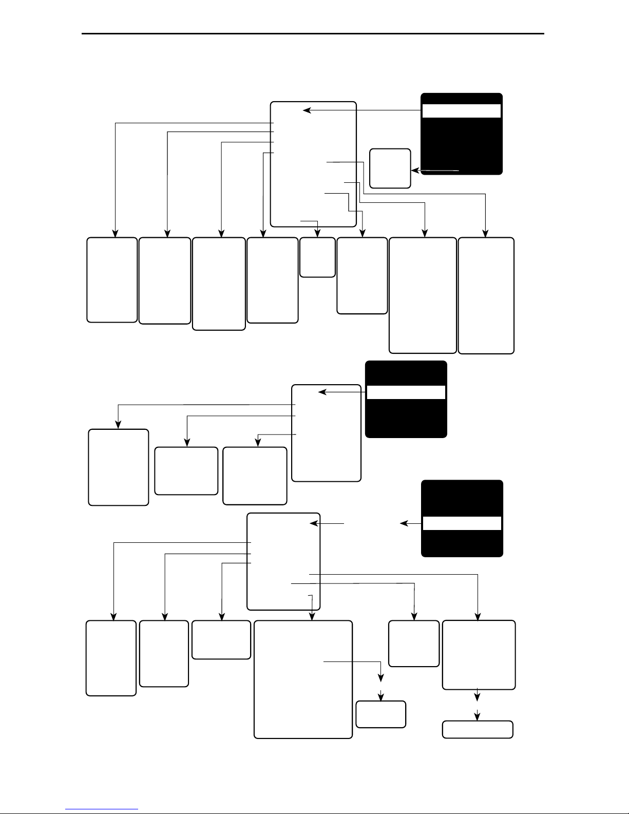
Menu Hierarchy
Status
System and Test Status
IP Path Connection Status
PVC Connection Status
Network Interface Status
IP Routing Table
(Management Traffic)
Performance Statistics
Trap Event Log
Display LEDs
and Control Leads
Identity
Command
Line
Interface
MAIN MENU
Status
Test
Configuration
Control
Easy Install
Shift-r
System and
Test Status
• Self-Test
Results
• Last Reset
• Health and
Status
• T est Status
Network
PVC Tests
(DLCI Number)
• PVC Loopback
• Send Pattern
• Monitor Pattern
• Connectivity
IP Path
Connection
Status
• Device Name
• IP Address
• Status
• Discovery
Source
Network ATM
Loopback T ests
(VPI, VCI)
• ATM Ping
PVC
Connection
Status
• Source Link,
DLCI, EDLCI
• Primary
Destination
Link, DLCI,
EDLCI Status
Network
Physical T ests
• T ransparent
Pass-through
• 511 Pattern Test
Network
Interface
Status
• Operating
Rate
• Receiver
Attenuation
• SNR Margin
Test
Network PVC Tests
Network ATM
Network Physical
Tests (9788)
IP Ping
Lamp T est
Abort All Tests
Configuration
Edit/Display
System
Network
Virtual Router Ports
PVC Connections
IP Path List
Management and
Communication
Identity
• System
• NAM
Loopback Tests
Trap Event
Log
• Number of
Trap Events
• Time Elapsed
Since Event
• Event
Performance
Statistics
• Service Level
Verification (SLV)
• DLCI
• Frame Relay
• ATM
• VCC
• xDSL Line (9788)
• Ethernet
• Clear All Statistics
MAIN MENU
Status
Test
Configuration
Control
Easy Install
Load
Configuration
From:
IP Routing
Table for
Management
Traffic
• Destination
• Mask
• Gateway
• Hop
• T ype
• Interface
• TTL
MAIN MENU
Status
Test
Configuration
Control
Easy Install
System
• Class of
Service
Definitions
• Service Level
Verification
• General
Network
• Physical
• Frame Relay
• Circuit
Records
• ATM
Virtual Router
Ports
• DLCI Records
Management and
Communication
• Node IP
• Management PVCs
• General SNMP Management
• Telnet and FTP Sessions
• SNMP NMS Security
• SNMP Traps
• Ethernet Management
• Communication Port
• External Modem (Com Port)
2
IP Path List
• Add and
Display Static
Paths
New or Modify
Management
PVC Entry
PVC Connection
Table
• Source Link, DLCI,
EDLCI
• Primary Destination
Link, DLCI, EDLCI
New or Modify
PVC Connection Entry
02-16974a-01
Page 3
Control
System Information
Administer Logins
Change Operating Mode
Select Software Release
Reset Device
MAIN MENU
Status
Test
Configuration
Control
Easy Install
System Information
• Device Name
• System Name,
Location, Contact
• ATM Location ID
• Date
• Time
Easy Install
• DSLAM T ype (9783)
• Node IP Address
• Node Subnet Mask
• TS Access
• Create Dedicated Network Management Link
• Ethernet Management Options Screen
• Network 1 DSL Line Rate (Kbps)
• Network 1 FRF.8 Encapsulation Mode
Administer Logins
• Login ID
• Password
• Access Level
New
Login Entry
Configuratio n Ro le s
Select Software Release
• Current Release
• Alternate Release
MAIN MENU
Status
Test
Configuration
Control
Easy Install
01-16974b
The Fr ameSa v er DSL Rout er has se v era l inte rf aces that ma y be pr ovis ioned b y diff er ent
parties:
Frame relay, ATM, and physical layer provisioning – Typically set up by the
CLEC (Competitive Local Exchange Car rier) or the frame relay NSP (Network
Service Provider ), using the menu-driven interface accessed via an ASCII terminal
connecti on or Tel net session.
Router pr ovi sionin g with Comm and Line Inter face ( CLI) – Typica lly accessed b y
the end user or a frame relay NSP that provides managed rout er service.
SLM provisioning – Typically set up b y the CLEC or frame relay NSP.
3
Page 4

Configuration Option Summaries
The fol lowing sections summarize the configuration options accessed when you select
Configuration from the Main Menu.
System Configuration Options
Fr om th e Confi gurat ion m enu, sel ect Sy stem to conf igur e opti ons appli cabl e to t he entir e
system.
Class of Service Definitions
Service Level Verification
General
Class of Service Definitions
Select Class of Service Defi nitions to confi gure class of service and code poin t
definitions.
Class of Service Definitions
Configuration Option Settings
Class of Svc Name
Measure Latency & Availability N, Y
Code Points Assigned N, Y
ASCII text
(8 characters)
Code Point Definitions
Code Pnt 000000–111111
ID 1–7
Name
ASCII text
(8 characters)
Default in
[Bold]
4
Page 5

Service Level Verification
Select Service Level Verification to confi gure SLV options for the rout er.
Service Level Verification
Configuration Option Settings
SLV Sample Interval (secs.) 10–3600 [60]
SLV Synchronization Rol e [
Tributary
], Controller, None
SLV Type Standard, COS 1–COS 7
SLV Delivery Ratio Enable, [
DLCI Down on SLV Timeout Enable, [
SLV Timeout Error Event
1–20 [3]
Disable
Disable
]
]
Threshold
SLV Timeout Clearing Event
[1]–20
Threshold
SLV Round Trip Latency Error
50–[
10000
]
Threshold (ms)
SLV Latency Clearing Event
1–20 [2]
Threshold
Default in [
Bold
]
SL V Packet Size (bytes) [64]–2048
General
Select Gener al to configure a timeout period and duration for user-initi ated loopback s
and pattern tests.
General
Configuration Option Settings
Test Timeout [
Enable],
Disable
Test Duration (min.) 1–120 [10]
Default in [
Bold
]
5
Page 6

Network Configuration Option s
From the Configurati on m enu, select Network to configure options applicable to the
network interface.
Physical
Frame Relay
Circuit Records
ATM
Physical
Select Ph ysical to configu re physical characteristics for the DSL network interface.
Physical (9783)
Configuration Option Settings
Line Rate Mode Hunt, [
DSL Line Rate (Kbps)
The defaul t and avail able line r ates depend on
AutoRate
Default in [
], Fixed
Bold
the setting of DSLAM Type. See Easy Install in
the Installat ion Instructions .
144, 192, 208, 256, 272, 384, 400, 512, 528,
768, 784, 1024, 1152, 1168, 1536, 1552, 2320
SNR Margin Alarm Threshold (dB) –5, –4, –3, –2, –1, 0, 1, 2, [3], 4, 5, 6, 7, 8,
9, 1 0
]
6
Page 7

Physical (9788)
Configuration Option Settings
Line Rate Mode [
DSL Line Rate (Kbps)
AutoRate
If PSD Mask is Symmetric:
], Fixed
Default in [
200, 264, 328, 392,
Bold
456, 520, 58 4, 648, 712, 77 6, 784, 840, 90 4, 968,
1032, 1096, 1160, 12 24, 12 88, 1352, 141 6, 1480 ,
1544, 1552, 1608, 16 72, 17 36, 1800, 186 4, 1928 ,
1992, 2056, 2120, 2184, 2248, 2312
If PSD Mask is Asymmet ric and Reg ion Setti ng is
Annex A:
776, 784, 1544, 1552
If PSD Mask is Asymmet ric and Reg ion Setti ng is
Annex B:
2056, 2312
Region Setting Annex A, Annex B
PSD Mask Asymmetric, [
Symmetric
]
Frame Relay
Select Frame Relay to specify whether Traffic Policing will be used on the DSL network
interface.
]
Frame Relay
Configuration Option Settings
Traffic Policing [
Enable
], Disable
Default in [
Bold
]
7
Page 8

Circuit Records
Select Circuit Records to manually configure Circuit Records for each interface.
Circ uit Reco rds
Configuration Option Settings
DLCI Number 16–1007 [
DLCI Type Standard, [
VPI 0–15 [
VCI 32–255 [
blank
Multiplexed
blank
]
blank
]
], IP Enabled
]
CIR (bps) [0]–2320000 (9783)
[0]–2312000 (9788)
T
c
This field displays the committed rate
measurement interval to be used for the DLCI
based upon the displayed option settings.
Committed Burst Size Bc (Bits ) [
B
[
c
CIR
], Other
0
]–2320000 (9783)
[0]–2312000 (9788)
0–[
2320000
2312000
] (9783)
] (9788)
Excess Burst Size B
(Bits) 0–[
e
Default in [
Bold
]
Outbound Managemen t Priority Low, [
Medium
], High
8
Page 9

ATM
Select ATM to configure the ATM characterist ics for the DSL network interface .
ATM
Configuration Option Settings
Cell Payload Scrambling [
Cell Delineation Error Event
Enable
1–1000 [10]
], Disable
Default in [
Threshold
FRF.8 Encapsul ati on Mode [
Transparent
], Translation
Virtual Route r Port Con figuration Options
From the Configurati on menu, select Virtual Router Ports, then DLCI Recor ds to
configu re DLCI Records on the vi rtual router port ( S0 – Serial Port 0).
DLCI Records
Configuration Option Settings
DLCI Number 16–1007
CIR (bps) [0]–2320000 (9783)
[0]–2312000 (9788)
Default in [
Bold
Bold
]
]
T
c
This field displays the committed rate
measurement interval to be used for the DLCI
based upon the displayed option settings.
Committed Burst Size Bc (Bits ) [
B
[
c
CIR
], Other
0
]–2320000 (9783)
[0]–2312000 (9788)
0–[
2320000
2312000
] (9783)
] (9788)
High
]
Excess Burst Size B
(Bits) 0–[
e
DLCI Priority Low, Medi um, [
9
Page 10

IP Path List
Select IP P ath List (Sta ti c) to configure the list of static path IP add resses.
IP Path List
Configuration Option Settings
Default in
[Bold]
IP Address 000.000.000.001–223.255.255.255
FWD [No], Yes
PVC C o nnection s Co nfiguration Op tions
From the Configurati on m enu, select PVC Connect ions to manually configure logical
connections.
The C
configuration of PVC connections. For management PVC configuration options, see
Management PVCs
reatePVC functi on key on the Network Circuit Records screen provides easy
on page 12.
PVC Connections
Configuration Option Settings
]
blank
]
Source Link Rtr-S0, Net1-FR1 [
Source DLCI 16–1007 [
blank
Default in [
Bold
]
Source EDLCI 0–62 [
blank
Destination Li nk Net1-FR1 [
Destination DLCI 16–1007 [
Destination EDLCI 0–62
[blank
]
blank
blank
]
]
]
10
Page 11

Management and Communication Configuration Options
From the Configuration menu, s elect Management and Communication to configure the
FrameSaver router so it can be managed by an NMS or via a Telnet session and to
select app ropri ate protocols.
Node IP
Management PVCs
General SNMP Managem ent
Telnet and FTP Sessions
SNMP NMS Security
SNMP Traps
Ethernet Management
Communicati on Port
Node IP
Select Node IP to configure support of the IP communication network.
Node IP
Configuration Option Settings
Node IP Address 001.000.000.000–2 23.255.255.255, [
Node Subnet Mask [
Default IP Destination [
TS Access Management Link [
TS Management Link
Access Level
000.000.000.000
None
], COM, Ethernet,
None
],
PVCname
Level-1
[
], Level-2, Level-3
]–255.255.255.255, Cle ar
PVCname
Default in [
Clear
]
Bold
]
11
Page 12

Management PVCs
Select Management PVCs to configure a management PVC for in-band management.
The C
configuration of network management PVCs.
reatePVC functi on key on the Network Circuit Records screen provides easy
Management PVCs
Configuration Option Settings
Name
ASCII text entry
Payl oad Managed Enable, [
Intf IP A ddress [
Intf Subnet Mask [
Node-IP-Address
Special
(001.000.000.000–223.255.255.255
Node-Subnet-Mask
Special (
Primary Link Net1-FR1
Primary DLCI 16–1007
Primary EDLCI 0–62
Encapsulation [
Routed
Disable
000.000.000.000–255.255.255.255
,
Rtr-S0, Clear
blank
[
blank
[
]
blank
[
] (8 characters)
]
],
], Calculat e,
blank
[
]
]
Primary Link RIP None, Proprietary, Standard_out
Proprietary
[
] for management links on
multip lexed Network D LCI s.
Default in [
]
Bold
)
)
]
Standard_out
[
] for management links on
standard Network D LCIs.
None
[
] for management li nks on Virtual Router
Port DLCIs.
12
Page 13

Genera l SNMP Man age m en t
Select Gener al SNMP Management to configure the FrameSaver router so it can be
managed as an SNMP agent.
Genera l SN MP Manage m ent
Configuration Option Settings
SNMP Management [
Community Name 1
Name 1 Access Read, [
Community Name 2
Name 2 Access [
Enable
ASCII text entry,
Read/Write
ASCII text entry
Read
], Read/Write
], Disable
, [
public
[
]
Clear
Default in [
], Clear
]
Bold
Telnet and FTP Sessions
Select Telnet and FTP Sessi ons to configur e access to the FrameSaver router through
Telnet or FTP, and to specify the access level when security is required.
Telnet and FTP Session s
Configuration Option Settings
Default in [
Bold
]
]
Telnet Session [
Enable
Telnet Login Required Enable, [
Session Access Level [
Inactivity Timeout [
Disconnect Time (Min utes) 1–60
FTP Session [
Level-1
Enable
Enable
FTP Login Required Enable, [
1–[
2320
2312
FTP Max Transfer Rate (Kbps) 1–[
], Disable
Disable
]
], Level-2, Level-3
], Disable
[10]
], Disable
Disable
]
] (9783)
] (9788)
13
Page 14

SNMP NM S Security
Select SNMP NMS Se curity to conf igure acc ess to t he F r ameSa v er router when securit y
is required.
SNMP NMS Security
Configuration Option Settings
NMS IP Validation Enable, [
Number of Managers [1]–10
Disable
]
NMS n IP Address 001.000.000.000–223.255.255.255, [
Access Type [
Read
], Read/Write
Default in [
Clear
]
Bold
]
SNMP Traps
Select SNMP Traps to configu re desired SNMP t raps and the interfaces over which they
will be sent.
SNMP Traps
Configuration Option Settings
SNMP Traps Enable, [
Disable
Default in [
]
Bold
]
Number of Trap Managers [1]–6
NMS
n
IP Address 001.000.000.000–223.255.255.255, [
Initial Route Desti nation [
AutoRoute
], Ethernet, COM,
General Traps Disable, Warm, AuthFail, [
Enterprise Specific Traps [
Li nk Traps Di s able, Up, Down, [
Link Traps Interfaces Network, Por ts, [
DLCI Traps on Interf aces Network, P orts , [
DLCI Traps on Interf aces – Filter [
RMON Traps [
Latency Traps Enable, [
IP SLV Availabi lityTraps [
Enable
Normal
Enable
Enable
], Disable
], Filter
], Disable
Disable
], Disable
All
]
All
], None
]
Both
Both
]
Clear
PVCname
]
]
14
Page 15

Ethernet Management
Select Ethernet Management to configure the router for user and management data on
the Ethernet interface.
Ethernet Management
Configuration Option Settings
Status [
Enable
], Disable
Default in [
IP Address 001.000.000.000–223.255.255.255, [
Subnet Mask [
000.000.000.000
]–255
.
255.255.255,Clear
Default G ateway Address 001.000.000.000–223.255.255.255, [
Proxy ARP Enable, [
Disable
]
Comm u nica ti o n Port
Select Communi cation Port to configure the FrameSaver router’s COM po rt .
Communication Port
Configuration Option Settings
Port Use [
When Port Use is set to Terminal:
Terminal
], Net Link
Default in [
Clear
Clear
]
]
Bold
Bold
]
]
Data Rate (Kbps) 9.6, 14.4, [
19.2
], 28.8, 38.4, 57.6, 115.2
Character Length 7, [8]
Parity [
None
], Even, Odd
Stop Bits [1], 2
Ignore Control Lead s [
Login Required Enable, [
Po rt Access Level [
Inactivity Timeout [
Disable
Level-1
Enable
], DTR
Disable
]
], Level-2, Level-3
], Disable
Disconnect Time (Min utes) 1–60 [10]
When Port Use is set to Net Link:
IP Address 001.000.000.000–223.255.255.255, [
Subnet Mask [
RIP [
000.000.000.000
None
], Standard_out
]–255
.
255.255.255, Clear
Clear
]
15
Page 16

Command L ine Summaries
Command Line Interface (CLI) Configuration options are l isted alphabetically in Table 1,
Configuration Commands. The abbreviated ( minimal) input for each command is
included.
For additional CLI summaries, refer to
Summary
refer to
To access the router’s CLI, press Shift-r from the Main Menu.
on page 21 and
CLI Commands, Codes, and Designations
Show Commands
Access Control and System Level Command
on page 22. For det ai ls on eac h command ,
in the User’s Guide
.
Document Conventions
The conventions used in Command Line syntax are shown below. The CLI is not
case-sensitive, with exception to the Password field.
Convention Translation
[ ]
{ }
|
[{ }]
Brackets indicate an optional element.
Braces indicate a required entry.
Vertical bars sepa rate mutually exclusive elements.
Braces within bracke ts i ndicate a required choi ce within an optional
element.
Italics
Bold
Entry is a variable, which the oper ator must supply.
Entry must be typed as show n, or the minimum char acters that must
be entered.
16
Page 17

Command Line Interface Configuration
Command Line Configuration options are listed alphabetically in Table 1, Configuration
Commands. The abbreviated input f or each comman d is included; the minim um number
of charac ters that can be entered in the command are shown in
Bold
.
For the default settings, see
Command Line Interface Default Settings
Table 1. Configuration Commands (1 of 3)
Command
|
cess-list
ac
{ {
src-ip [ src-wildcard
{
protocol { src-ip src-wildcard
[
{
[ [
[
type-code
{
no ac
{ {
src-ip [ src-wildcard
{
protocol { src-ip src-wildcard
[
{
[ [
[
access-list-num
dest-i p dest-wildcard
[ range
cess-list
access-list-num
dest-i p dest-wildcard
src-operator src-port [ src-end-port
icmp-msg-type [ icmp-msg-code
dest-operator dest-port
src-operator src-port [ src-end-port
icmp-msg-type [ icmp-msg-code
dest-oper ator dest-port
{ per mit
|
any | host
]
end-type-code
|
any | host
]
deny }
src-host-ip
| any | host
| any | host
] } }
[ { permit
| any | host
| any | host
|
src-host-ip
|
}
src-host-ip
dest-host-ip
[
dest-end-port
deny }
|
}
src-host-ip
dest-host-ip
[
dest-end-port
] ]
] ]
] ]
] ]
}
|
}
|
on page 20.
}
] ] ] } |
}
] ] ] } |
type-code
{
p
ip-addr ess m ac-address arp-type
ar
p
no ar
arp t
ip-address [ mac-address arp-type
imeout
no arp t
ridge { crb
b
tocol
pro
oute
r
o bridge { crb
n
ority [
pri
[
o] bridge-group
n
[
o] bridge-group
n
{input-type-list
utput-type- list
o
ear arp-cache
cl
[ range
time
imeout [
route-protocol
tim e
|
bridge-group
span-tree-protocol
|
bridge-group
span-tree-priority
bridge-group
bridge-group
in-access-list-200num
out-access-list-200num
end-type-code
]
} }
{ acquire
|
pri
{ acquire
|
]
r
] } } ]
|
ag
ority
|
oute [
|
]
ing-time
span-tree-priority
ag
route-protocol
}
aging-time
ing-time [
|
|
aging-time
] } }
|
]
17
Page 18

Table 1. Configuration Commands (2 of 3)
Command
cl
ear counters [
cl
ear ip nat translations *
d
efault-router
d
n
o
efaul t-router [
dn
s-server
ip-address
intf-type intf-num [.sub-intf-num
ip-address
ip-address
]
] ]
no dn
do
no do
enc
[no] frame-relay interface-dlci
in
no in
ip ad
no ip ad
n
[
n
[
ip dhcp r
n
s-server [
main-name
main-name [
apsulation
terface
ip ac
o]
ip dhcp p
o]
ip dhcp r
o
intf-type intf-num[.sub-intf-num
terface
dress
dress [
ip-address
domain-name
doma in- n ame
encapsulation-type encapsulation-protocol
intf-type intf-num.sub-intf-num
ip-addr subnet-mask
ip-addr subn et-mask
cess-group
ool
elay max-clients
elay max-clients [
]
access-list-1-199num
pool-name
]
dlci-num
[ point-to-point ] ]
[ point-to-point ]
]
[
max-dhcp-clients
max-dhcp-clients
i
n | out ]
]
ip dhcp
n
[
o]
ip m
[no]
no] ip n
[
n
ip n
[
o]
l
ist
{
l
s
n
o]
[
{
access-list-1– 99num
ist
access-list-1– 99num
tatic {
protocol static-ip-addr1 static-port-num static-ip-addr2
ip n
n
etmask
-
server
ulticast-routing
|
at { inside
at inside source
static-ip-addr1 static-ip-addr2
at pool
netmask
pool-name start-ip-addr end-ip-addr
ip-address
o
uts ide }
p
i
nterface
|
p
{
refix-length
ool
pool-name
|
[ overl oa d ]
int f-type intf-nu m[.sub-intf-num
|
|
/ }
prefix-length
18
} }
}
] overload |
Page 19

Table 1. Configuration Commands (3 of 3)
Command
ip n
at translation timeout
time
n
o
ip route
ip
n
at translation timeout [
dest-ip dest-mask
no ip route
n
ip routi
[
o]
no
ip un
[
]
l
ease {
n
l
o
ease [
ne
twork
n
etmask ]
[ [
no ne
[ [ netmask ]
pi
ng [
[
[
t
n
o] service dhcp
numbered [null 0]
days
[
days
network-num
netmask
twor k [
netmask
protocol
imeout
time
]
{
next-hop-ip
dest-ip dest-mask [next-hop-ip
ng
|
hours
network-num
]
time
[
hours
dest-ip
] [
] [
minutes
] [
|
{
| {
p
[ source source- ip ] [ length bytes ]
i
nterface
minutes
p
refix-length
refix-length
i
]
nfinite }
|
i
]
nfinite ]
|
|
intf-t y pe intf -n u m[.sub-intf-num
|
intf-type intf-num[.sub-intf-num
|
intf-type intf-num[.sub-intf-num
prefix-length
/ }
prefix-length
/ }
] ]
] ] ]
] }
] ]
] ]
t
raceroute [
t
imeout
[
protocol ] dest-ip
time
] [ hops
[ source
hops
] [ interface
source-ip
intf-type intf-num[.sub-intf-num
] [ length
bytes
]
] ]
19
Page 20

Command Line Interface Default Settings
The fol lowi ng list shows the default settings:
!software version d1.06.04
!
no enable password
ip routing
no ip multicast-routing
service dhcp
ip nat translation timeout 86400
ip dhcp relay max-clients 256
bridge 1 acquire
bridge 1 aging-time 300
bridge 1 protocol ieee
bridge 1 priority 32768
interface Ethernet 0
bridge-group 1
arp timeout 14400
!
interface Serial 0
Encapsulation frame-relay ietf
bridge-group 1
!
end
20
Page 21

Access Control and System Level Command Summary
Table 2, Access Control and Sytem Level Commands, lists all the Access Control and
System Level Commands for the CLI.
Table 2. Access Contro l and Sytem Level Commands
Command Function
?
!
co
nfigure { terminal
d
isable Exits the Administrator access level.
en
able Enters/ enables the Administrator access
en
able password
no en
able password [
|
f
actory } Enters configuration mode so configuration
password
passwo rd
]
end
ex
it Leaves the current configuration level or
Displa ys all valid comm ands for the current
access level.
Used to enter comments. Comments that
follow the ! are ignored by the CLI.
options can be edited .
level.
Sets or disables the password level. Default
is None.
Leaves configur ation mode to return to
standard operating mode.
terminates the session. It may be necessary
to enter the exit command several times
when leavin g configuratio n m ode.
h
elp Displays a summary of help options.
n
[
o] pager Enables/ specifies screen paging for a CLI
r
eload Resets the router and reloads its
sa
ve Saves changes to the router ’s configuration.
session.
configuration.
21
Page 22

Show Commands
Table 3, Show Commands, lists all the di splay request s for the CLI.
Table 3. Show Commands
Command Function
s
how arp Displa ys al l t he de vic es in t he rou ter’s ARP
table.
s
how bridge Displays the router’s bridge forwarding
database entries.
s
how configuration Displays the router’s current configuration.
s
how configuration { saved | unsaved } Shows the current configuration, either
saved in memory or entered during the
current session.
s
how frame-relay map Shows the status of all frame relay DLCIs
on the router’s frame relay interface.
s
how interface
intf-type intf-num [.sub-intf-num
[
s
how ip nat translations Displays all the router’s activ e NAT
s
how ip dhcp binding [
s
how ip route [
s
how ip traffic Shows the IP statistics for the router.
s
how spanning-tree Displays the router’s spanning-tree
ip-address
ip-address
] ]
] Shows the address bi ndings associate d
] Shows the Routi ng Table entry for the
Shows the st atus of the s pecified int erfac e,
sub-int erface, or all interfaces and
sub-int erfaces for the router.
translations.
with the DHCP server.
If an IP address is specified, only
bindings fo r that cli ent wil l be d ispla y ed.
If no IP address is spe cif ied, all DHCP
bindings wil l be di splayed.
device with the specifi ed IP address, or
all Routing Table entri es if no IP address
is specified.
topology.
22
Page 23

Warr anty, Sale s , Se rvi ce, a nd Training I nforma tion
Contact y our local sales repr esentative, service repres entative , or distributor directly f or
any help needed. For additi onal information concerning warranty, sales, service, repair,
installation, documentation, train ing, distributor locations, or Parady ne worldwide office
locations, use one of the following methods:
Inte rn e t: Visit the P aradyne World Wide Web site at www.paradyne.com.
(Be sure to register your warr anty at www.paradyne.com/warranty.)
Tel ephone: Call our automated system to receive current information by fax or to
speak with a company representati ve.
— Within th e U.S.A., call 1-800-870- 2221
— Outside th e U.S.A., call 1-727-530-2340
Document Feedback
We w elcome y our comment s an d suggest ions abo ut this do cument . Plea se mail them to
Technical Pub lications, Parad yne Corpor ation, 8545 126th A ve. N., Largo, FL 33773, or
send e-mail to userdoc@paradyne.com. Include the number and title of this document
in your correspondence. Please include your name and phone number if you are willing
to provide additional clarification.
Trademarks
FrameSaver is a registered trademark of Paradyne Corporation. All other products and
services mentioned are the trademarks, service marks, registered trademarks, or
registered service marks of their respective owners.
Patent N o tification
FrameSav er products are protected by U .S. P atents: 5,550,700 and 5,654,966. Other
U.S. patents pending.
Copyright © 2002 Paradyne Corporation. Printed in U.S.A.
23
Page 24

*9700-A2-GL11-00*
 Loading...