

Page 1

FrameSaver® 9623 Router
Installation Instructions
Document Number 9623-A2-GN11-00
March 2003
Contents
Product Documentation Online ..................................................................... 2
Upgrading a Unit to the Advanced SLM Feature Set .................................... 2
Package Checklist ......................................................................................... 2
Preparation ................................................................................................... 3
Cables You May Need to Order .................................................................... 3
Safety Instructions ........................................................................................ 4
Installing the Power Supply and Cord ........................................................... 4
Connecting to an Asynchronous Terminal or PC .......................................... 5
Verifying that Self-Test Passed ..................................................................... 5
Menu Hierarchy ............................................................................................. 6
A Quick Guide to Configuration .................................................................... 9
About the Installation Procedures ................................................................. 10
Full Installation and Setup ............................................................................ 10
Minimal Installation for Service Providers ..................................................... 12
Setting Up Local Management at the Central Site ........................................ 13
Automatic Configuration ................................................................................ 13
Connecting to the Network ........................................................................... 14
Configuring SNMP Trap Managers and Traps .............................................. 15
Connecting to the Ethernet ........................................................................... 16
Verifying That Data is Being Received .......................................................... 17
Checking PVC Connections .......................................................................... 17
Provisioning the Router Interface .................................................................. 17
Important Safety Instructions ....................................................................... 18
Warranty, Sales, Service, and Training Information ...................................... 22
Document Feedback ..................................................................................... 22
Trademarks ................................................................................................... 22
Patent Notification ......................................................................................... 22
1
Page 2

Product Documentation Online
Complete documentation for this product is available at www.paradyne.com.
Select
Select the following documents:
Support
→
Technical Manuals
→
FrameSaver Frame Relay Devices.
FrameSaver SLV Technical Description
FrameSaver SLV Configuration Reference
FrameSaver SLV SNMP Reference
FrameSaver SLV Operations Guide
FrameSaver SLV Router Command Line Interface
To order a paper copy of a Paradyne document, or to speak with a sales representative,
please call 1-727-530-2000.
(9000-A2-GB30)
(9000-A2-GB31)
(9000-A2-GB32)
(9000-A2-GB33)
(9000-A2-GB34)
Upgrading a Unit to the Advanced SLM Feature Set
Full Service Level Management (SLM) capability can be activated in units that have the
basic diagnostic feature set at any time. This is an optional feature that adds real-time
and historical network performance monitoring and SLA (Service Level Agreement)
reporting capabilities to your FrameSaver unit and network. Simply order a Feature
Activation Certificate and provide the model to be activated, your OpenLane
system license key number, and the number of FrameSaver units to be activated to
SLM capability. You can order the certificate for a single unit or for many units.
OpenLane SLM Release 5.3 or above is required to schedule activation of SLM features
in units, and to manage the number of activations remaining on the certificate.
OpenLane also provides a Certificate Summary Report to assist you in the management
of the certificate.
®
SLM
When the Feature Activation Certificate arrives, add the Activation Certificate Number to
your OpenLane SLM application’s database. Activations can occur at any time, for as
many units as desired, until no activations remain for the certificate. When ready to
activate units, simply select the units to be activated and schedule the activations. The
activations occur when scheduled, and OpenLane updates the certificate information.
Contact your sales representative for additional information.
Package Checklist
Verify that your package contains the following:
❑ FrameSaver FLEX unit
❑ Power cord with a wall-mount 120 VAC power transformer
❑ Self-mounting tie wrap for power cord strain relief
❑ RJ48S modular cable for U.S. network access
Be sure to register your warranty at www.paradyne.com/warranty.
2
Page 3

Preparation
Make sure you have:
❑ A dedicated, grounded power outlet that is protected by a circuit breaker within
6 feet of the FrameSaver unit
❑ A clean, well-lit, and ventilated site that is free from environmental extremes
❑ One-to-two feet of clearance for cable connections
❑ A physical connection to the frame relay DDS network
❑ An asynchronous terminal or PC (personal computer)
❑ If desired, an operable Ethernet LAN (Local Area Network) connection for access
by an NMS (Network Management System)
❑ Configuration information for the FrameSaver unit being installed or replaced
❑ Appropriate cables:
— Ethernet cable
— Data port cable
— COM port-to-terminal or COM port-to-PC cable
See the
information about technical specification, connectors, cables, and pin assignments. See
the
troubleshooting.
FrameSaver SLV Technical Description
FrameSaver SLV Operations Guide
(9000-A2-GB30) for additional
(9000-A2-GB33) for information about
Cables You May Need to Order
Feature
If connecting to . . . Order a . . .
Asynchronous
terminal or PC with an
8-pin modular
interface/connector
PC with a D-Sub9
interface/connector
External device
(such as a modem)
Standard EIA-232
straight-through cable,
8-pin modular-to-DB25
(14 feet – 4.3 meters)
Standard EIA-232
straight-through cable,
D-Sub9-to-DB25
(14 feet – 4.3 meters)
Standard EIA-232-D
crossover cable
(14 feet – 4.3 meters)
Number Part Number
3100-F2-540 035-0314-1431
3100-F2-550 035-0313-1431
9008-F1-550 035-0336-1431
Contact your sales representative to order cables.
3
Page 4
Safety Instructions
Please refer to the
Important Safety Instructions
on page 18.
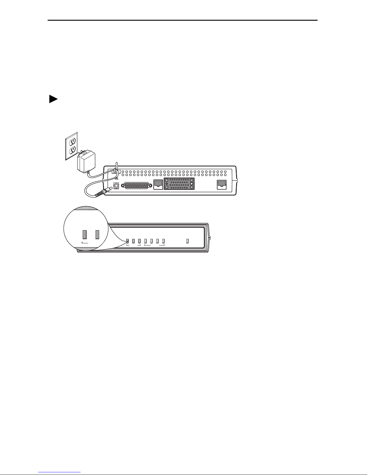
Installing the Power Supply and Cord
Procedure
1. Insert the power cord’s plug into the POWER jack.
Grounded
Power
Outlet
OK
ALM
System
®
FLEX
FrameSaver
FrameSaverTMSLV
POWER
COM
ALM
OK
9623
TESTFRDM
ETHERNET
NetworkSystem
P
O
R
T
OOS
OOF/NS
OK
Port
NET
00-16699
2. Plug the power supply into the grounded power outlet and check the LEDs.
If any LEDs light, you have power. If not, refer to
FrameSaver SLV Operations Guide
for possible explanations.
Troubleshooting
in the
3. Insert the self-mounting tie wrap in the leftmost hole (hole with a dark circle around
it) until it snaps securely into place. The tie wrap provides strain relief for the power
cord.
4. Loop the tie wrap around the power cord, thread it through the hole at the base of
the wrap, and pull it snugly around the cord.
4
Page 5
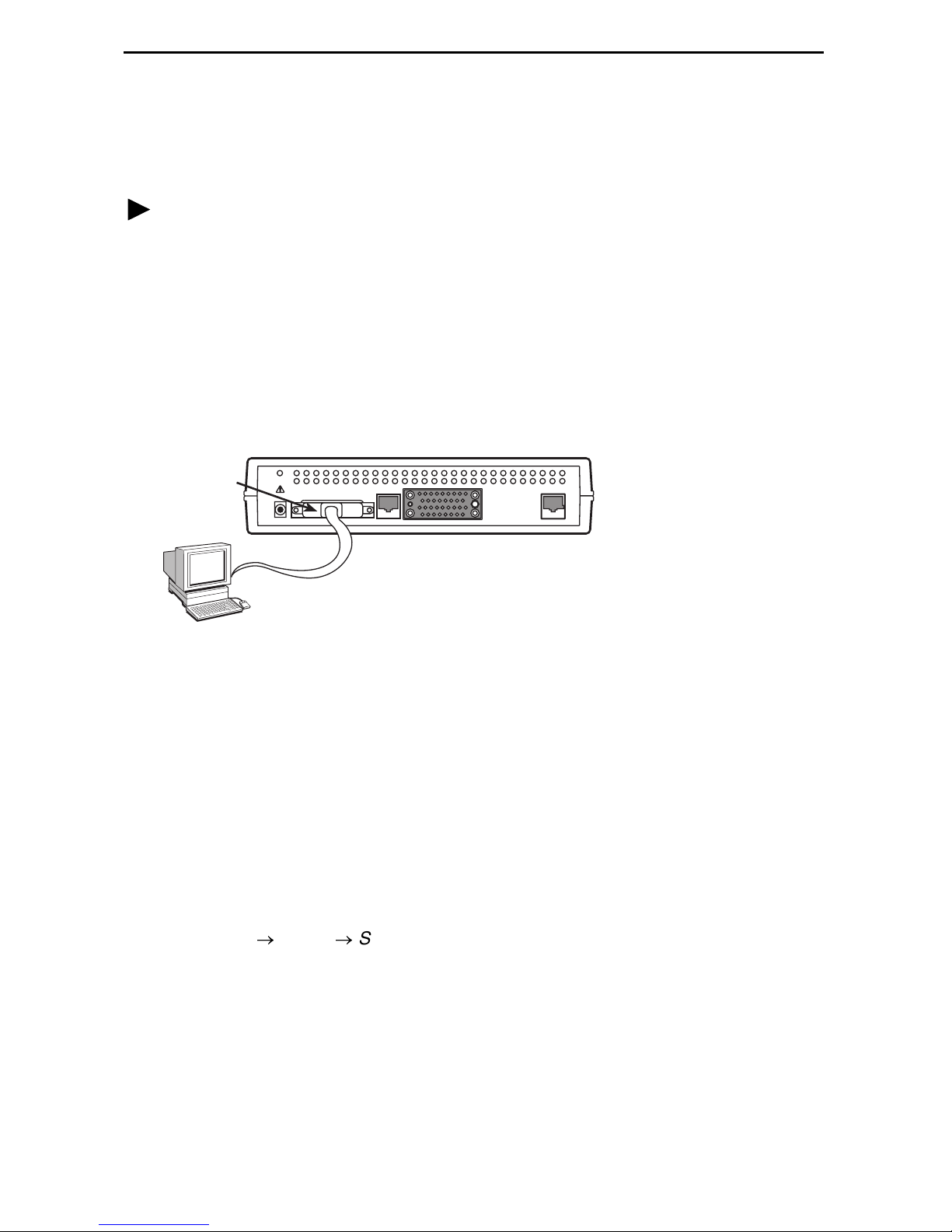
Connecting to an Asynchronous Terminal or PC
A VT100-compatible asynchronous terminal or a PC providing VT100 terminal
emulation must be used to set up access to and management of the unit.
Procedure
1. Configure the terminal or PC so it is compatible with the FrameSaver unit:
— Baud Rate set to 19.2 kbps.
— Character length set to 8 data bits.
— Parity set to none.
— Stop bit set to 1.
— Flow Control set to None.
2. Insert the DB25 end of the EIA-232 cable into the FrameSaver unit’s COM port.
COM
Por t
POWER
COM
ETHERNET
P
0
R
T
NET
00-16685
3. Insert the other end of the cable into the terminal or PC.
4. Tighten the screws on each side of the connector to secure the cable.
5. Press Enter on the keyboard to display the Main Menu.
If the Main Menu does not appear, recheck the terminal or PC settings (see Step 1),
or press the Enter key. Refer to
Guide
for other possible explanations.
Troubleshooting
in the
FrameSaver SLV Operations
Verifying that Self-Test Passed
To verify that the unit passed its self-test, go to the System and Test Status screen.
Main Menu
→
Status
The results of the self-test appear directly under the screen title.
If any failure messages appear, reset the unit by disconnecting, then reconnecting the
power cord. The unit will perform the self-test again. If the failure reappears, call your
service representative for assistance.
→
System and Test Status
5
Page 6

Menu Hierarchy
The Menu Hierarchy shows the organization of the FrameSaver unit’s screens. Support
for all features may not be available in the firmware release you are running.
S ta t u s
System and Test
Status
LMI Reported
DLCIs
IP Path
Connection Status
PVC Connection
Status
Network Interface
Status
IP Routing Table
(Management
Traffic)
Self-Test Results
Last Reset
Health and Status
Tes t St a tu s
DLCI
Status
CIR (bps)
Device Name
IP Address
Status
Discovery Source
Source Link, DLCI, EDLCI
Primary Destination Link, DLCI,
EDCLCI, Status
Operating Rate
Loop Loss
Destination
Mask
Gateway
Hop
Ty pe
Interface
TTL
Performance
Statistics
T r a p E v e n t L o g Number of Trap Events
Display LEDs and
Control Leads
I d e n t i t y System
Service Level Verification
DLCI
Frame Relay
DDS Line
Ethernet
Clear All Statistics
Time of Day
Event
NAM
6
Page 7

Te st
Network PVC
Tests
PVC Loopback
Send Pattern
Monitor Pattern
Configuration
Network Physical
Tests
IP Ping
Lamp Test
Abort All Tests
System Frame Relay and LMI
Network Physical
Virtual Router
Ports
PVC Connections Source Link, DLCI, EDLCI
Local CSU Loopback
Local DSU LoopbackSend Pattern
Monitor Pattern
PPP
Class of Service Definitions
Service Level Verification
General
Frame Relay
PPP
DLCI Records
PPP
DLCI Records
Primary Destination Link, DLCI, EDLCI
AutoConfiguration
IP Path List Add and Display Static Paths
Management and
Communication
Options
Node IP
Management PVCs
General SNMP Management
Telnet and FTP Sessions
SNMP NMS Security
SNMP Traps
Ethernet Management
Communication Port
External Modem (on COM Port)
Frame Relay Discovery Mode
Automatic Circuit Removal
7
Page 8

Control
System
Information
Administer Logins Login ID
Device Name
System Name, Location, Contact
Date
Time
Password
Access Level
Easy Install
Change Operating
Mode
Select Software
Release
LMI Packet
Capture Utility
Telnet
Reset Device
Back-to-Back Mode
Standard Mode
Current Release
Alternate Release
Switch & Reset
Capture Interface
Packet Capture Start/Stop
Status
Packets in Buffer
Display LMI Trace Log
Service Type
Node IP Address
Node Subnet Mask
TS Access
Create Dedicated Network Mgmt Link
Ethernet Management Options Screen
Network 1 DDS Line Rate
8
Page 9

A Quick Guide to Configuration
The FrameSaver unit should operate using the default (factory-set) configuration
options, with exception to the changes specified in these installation instructions. Refer
to the following table for help in navigating through the menus.
Press the . . . To . . .
Esc key Go back one screen or menu level. To see a visual
representation of the menu levels, see
the Quick Reference.
Menu Hierarchy
in
Tab key, or
Up (↑), Down (↓),
Left (←) and Right (→)
Arrow keys
Enter or Return key Complete the menu or option selection.
Spacebar Display the next available setting when changing a
As an example, follow these steps to go to the Configuration Edit/Display menu so you
can start setting up the unit.
To load a configuration for editing:
1. From the Main Menu, press the down arrow key twice so the cursor is on
Configuration.
2. Press Enter to display the Configuration menu. The Load Configuration From menu
appears.
3. Press Enter to select Current Configuration (the cursor is already on this selection).
The Configuration Edit/Display menu appears.
Move the cursor from one menu item to the next.
configuration option. All the available settings for an option
appears at the bottom of the screen.
This sequence of steps would be shown as the menu selection sequence:
Main Menu → Configuration
To save a configuration option change:
1. Press Ctrl-a to switch to the function keys area at the bottom of the screen.
2. Ty pe s or S (Save) and press Enter. The Save Configuration To menu appears.
3. Press Enter again to save your changes to the Current Configuration.
4. Press Esc until the Configuration Edit/Display menu reappears to continue
configuring the unit.
Press Ctrl-a, type m (M
In the sections that follow, only the minimum option changes required are included so
you will have a quick and trouble-free installation. See the configuration option tables in
the User’s Guide for more information about configuration options.
ainMenu), and press Enter to return to the Main Menu.
9
Page 10

About the Installation Procedures
There are two methods for installing and setting up the FrameSaver unit.
One person can install and set up the unit. If this is the case, see
and Setup
An installer can physically install and set up access to the unit, and the network
.
operation center (NOC) can complete the setup. If this is the case, see
Installation for Service Providers
on page 12.
Full Installation
Minimal
Certain procedures are common to both the full installation and minimal methods. These
procedures (starting with
Setting Up Local Management at the Central Site
on page 13)
are referenced in the full and minimal installation instructions. Refer to them, as needed.
Full Installation and Setup
An Easy Install screen is provided to simplify installation and setup. The Easy Install
feature can be used when one person installs and sets up the FrameSaver unit from
beginning to end.
Procedure
1. Select the Easy Install feature.
Main Menu → Easy Install
Easy Install Screen Example
main/easy_install 9623-Rtr
Device Name: Node A 02/26/2003 23:32
EASY INSTALL
Node IP Address: 000.000.000.000 Clear
Node Subnet Mask: 000.000.000.000 Clear
TS Access: DLCI 980
Create a Dedicated Network Management Link
Ethernet Port Options Screen
Network 1 DDS Line Rate(Kbps): Initialize From Network
--------------------------------------------------------------------------Ctrl-a to access these functions, ESC for previous menu MainMenu Exit
Save
10
Page 11

2. Verify that the Service Type is Frame Relay.
3. Enter the Node IP Address and Subnet Mask.
4. Set TS Access to DLCI, then select a DLCI on the network interface that will be
used for the troubleshooting access link.
5. Create a Dedicated Network Management Link, selecting a DLCI for the
management link at the Which DLCI would you like to Create a
Dedicated Network Management Link on? prompt, which will be used by
the NOC to access the unit.
6. Select the Ethernet Port Options Screen, and configure the following:
— Enable Interface Status. If the NMS will be on a different subnet than the unit,
enter Y
Destination to Ethernet? prompt. Otherwise, enter N
es at the Would you like to set the Node's Default IP
o.
— If the IP Address and Subnet Mask are unique to the interface, enter them for
the port; otherwise, the Node IP Address and Subnet Mask will be used.
— Enter the Default Gateway Address; the IP Address that will be used for
packets without a route.
— Enable Proxy ARP if the unit will proxy for downstream FrameSaver units
learned via the proprietary RIP (Routing Information Protocol) feature.
— Press the Esc key to return to the Easy Install screen.
7. Configure the DDS network interface options to match the service provider’s
settings.
8. S
ave the configuration.
9. Install the network cable (see
Connecting to the Network
FrameSaver unit starts discovering DLCIs and network time slots (see
Configuration
10. Install the Ethernet cable (see
on page 13).
Connecting to the Ethernet
on page 14). The
Automatic
on page 16).
The remaining steps are optional, depending upon the application. They are performed
from the Main Menu.
11. If the unit will be enforcing CIR (Committed Information Rate) and EIR (Excess
Information Rate) on network frame relay links, enable Traffic Policing.
Main Menu → Configuration → System → Frame Relay and LMI
You can change other Frame Relay and LMI default settings, if necessary.
12. Configure each interface according to the local management interface (LMI) and
assigned line conditions supplied by the service provider.
Configuration → Network → Frame Relay
13. Set up SNMP management and local management (see
Management at the Central Site
14. If SNMP traps are wanted, set up managers and select the desired traps (see
Configuring SNMP Trap Managers and Traps
The FrameSaver installation is complete.
Setting Up Local
on page 13).
on page 15).
11
Page 12

Minimal Installation for Service Providers
Verify with your service provider that frame relay service is turned on at the site. Follow
Step 1 through Step 10 of
Physical installation of the unit is complete; the NOC can now remotely access the unit
for additional configuration.
Completing Setup of the Unit From the NOC
Procedure
1. Access the remote FrameSaver unit using the dedicated management link, using
the Node IP Address that was entered.
2. Configure specific frame relay options, like CIR (committed information rate), and
any other configuration options requiring input or changes from the default settings.
3. Configure the network interface according to the local management interface (LMI)
and assigned line conditions supplied by the service provider.
Full Installation and Setup
on page 10.
Configuration
4. If SNMP traps are wanted, set up managers, select the desired traps, and configure
trap dial-out if desired (see
page 15).
5. Save the configuration.
6. Verify that data is being received (see
page 17).
7. Verify that all PVCs, including Management PVCs, are configured; and see whether
the PVC is active or not (see
The FrameSaver installation is complete.
→
Network → Frame Relay
Configuring SNMP Trap Managers and Traps
Verifying That Data is Being Received
Checking PVC Connections
on
on
on page 17)
12
Page 13

Setting Up Local Management at the Central Site
Procedure
1. Create a DLCI for the data port.
Configuration → Data Ports → DLCI Records
2. Save the configuration.
3. Create a Management PVC using the data port DLCI just created.
Configuration → Management and Communication → Management PVC
Minimally, enter the following options:
— Name for the management PVC
— Interface IP Address and Subnet Mask, if different from the Node’s
— Primary Link for this Management PVC (the user data port)
— Primary DLCI (i.e., the data port DLCI)
4. Save the configuration.
Automatic Configuration
The FrameSaver unit provides several automatic configuration features. Frame Relay
Discovery and configuration is one of these features.
Main Menu → Auto-Configuration
The default discovery mode is 1PPort. In this mode:
Auto-Configuration is enabled on the virtual router port.
A virtual router port DLCI is created for each network DLCI and automatically
cross-connected to it.
Payload management is configured for the network DLCI and assigned the Node IP
Address.
NOTE:
When auto-configuration creates a multiplexed DLCI, but a standard DLCI is
needed, change the DLCI to Standard from the network DLCI Records screen:
Configuration
Other modes can be selected. See
of the
other modes and how the Frame Relay Discovery Mode can be changed.
FrameSaver SLV Configuration Reference (9000-A2-GB31)
→
Network → DLCI Records
Setting Up Automatic Configuration
in
Configuration
for information about
No automatic configuration occurs until the network cable is connected. If you do not
want management links configured or automatic configuration, change the default
setting for the Frame Relay Discovery feature.
13
Page 14

Connecting to the Network
Now that the FrameSaver unit is set up, the unit can be connected to the network.
Procedure
1. Insert the 8-pin connector of the RJ48S network cable into the network interface.
2. Insert the other end of the cable into the RJ48S modular jack.
RJ48S
POWER
COM
ETHERNET
P
0
R
T
NET
NOTE:
After connecting the network cable, wait about a minute to allow
Auto-Configuration a chance to discover the operating rate and the DLCIs.
Jack
00-16696
3. Verify that the Network out-of-service (OOS) and out-of-frame/no signal (OOF/NS)
LEDs are off. If so, the network interface is set up correctly and is operational. If not,
make sure both ends of the network cable are properly seated.
4. Check Health and Status messages in the left column of the System and Test
Status screen.
Main Menu → Status → System and Test Status
— If the Service Type is Frame Relay, see the LMI status and verify that LMI is
up. If LMI Down, Net1-FR1 appears for more than three minutes, or any
other network-related status message appears, refer to the status information
in
Operation and Maintenance
of the User’s Guide for possible reasons.
— If the Service Type is Lease Line, verify that the Leased Line Mode Active
message appears. If not, make sure both ends of the network cable are
properly seated.
14
Page 15

Configuring SNMP Trap Managers and Traps
Once the FrameSaver unit is connected to the network, SNMP trap managers and
SNMP traps can be configured.
Procedure
To enter SNMP managers and configure traps:
1. Select SNMP Traps.
Main Menu → Configuration → Management and Communication
SNMP Traps
2. Configure the following:
— Enable SNMP Traps.
— Identify the total Number of Trap Managers.
— Specify the IP address of the NMS(s) to which traps will be sent.
— Specify the Initial Route Destination for the Trap Manager(s).
— Select desired trap categories.
3. S
ave the configuration.
4. Return to the Main Menu.
→
15
Page 16

Connecting to the Ethernet
Procedure
1. Insert one 8-pin connector of the Ethernet cable into the Ethernet port.
2. Insert the other end of the cable into the Ethernet interface of the LAN where the
NMS resides.
POWER
COM
ETHERNET
P
O
R
T
NET
NMS
LAN
00-16687
3. Check Health and Status messages in the left column of the System and Test
Status screen to verify that there are no Ethernet-related Health and Status
messages.
Main Menu
→
Status
→
System and Test Status
If the Ethernet Link Down message appears, make sure both ends of the
Ethernet cable are properly seated.
16
Page 17

Verifying That Data is Being Received
Procedure
1. Return to the Main Menu.
2. Select Performance Statistics, and select an interface’s frame relay statistics.
Main Menu → Status → Performance Statistics →Frame Relay → Net1-FR1
3. Verify that the Frames Received and Characters Received counts under the Frame
Relay Link statistics are incrementing, and there are no errors under the Frame
Relay LMI statistics.
— If count increments occur after refreshing the screen, the unit is receiving data.
— If data is not being received, recheck the cable connections, and replace or
repair a damaged cable. Recheck LMI status; you may need to contact your
service provider. Next, check the DLCI’s status.
Checking PVC Connections
Procedure
Check PVC connections to verify that all PVCs, including management PVCs, are
configured, and to see whether the PVC is active or not.
1. Return to the Status menu.
2. Select PVC Connection Status.
The PVC Connection Status screen shows all PVC connections; the interface
source and DLCI number of the incoming data linked to the interface and DLCI
number for the outgoing data. You can also see whether the PVC is active.
3. Verify that each PVC is active.
— If active, the FrameSaver unit should be passing data.
— If not active, no data traffic can be carried by the PVC. If the PVC is configured
correctly, the circuit may be down.
The FrameSaver installation is complete.
Provisioning the Router Interface
The FrameSaver SLV 9123 Router defaults to bridge mode. Routing without bridging,
and simultaneous routing and bridging, are also options.
Use the bridge command from the router’s CLI to configure the bridge and routing
attributes. Also, enter an Ethernet IP address and a DHCP IP address. Refer to the
FrameSaver SLV Router Command Line Interface
settings.
for CLI commands and default
17
Page 18

!
Important Safety Instructions
1. Read and follow all warning notices and instructions marked on the product or
included in the manual.
2. Slots and openings in the cabinet are provided for ventilation. To ensure reliable
operation of the product and to protect it from overheating, these slots and
openings must not be blocked or covered.
3. Do not allow anything to rest on the power cord and do not locate the product where
persons will walk on the power cord.
4. Do not attempt to service this product yourself, as opening or removing covers may
expose you to dangerous high voltage points or other risks. Refer all servicing to
qualified service personnel.
5. General purpose cables are provided with this product. Special cables, which may
be required by the regulatory inspection authority for the installation site, are the
responsibility of the customer.
6. When installed in the final configuration, the product must comply with the
applicable Safety Standards and regulatory requirements of the country in which it
is installed. If necessary, consult with the appropriate regulatory agencies and
inspection authorities to ensure compliance.
7. A rare phenomenon can create a voltage potential between the earth grounds of
two or more buildings. If products installed in separate buildings are
interconnected, the voltage potential may cause a hazardous condition. Consult a
qualified electrical consultant to determine whether or not this phenomenon exists
and, if necessary, implement corrective action prior to interconnecting the products.
8. In addition, if the equipment is to be used with telecommunications circuits, take the
following precautions:
— Never install telephone wiring during a lightning storm.
— Never install telephone jacks in wet locations unless the jack is specifically
designed for wet locations.
— Never touch uninsulated telephone wires or terminals unless the telephone line
has been disconnected at the network interface.
— Use caution when installing or modifying telephone lines.
— Avoid using a telephone (other than a cordless type) during an electrical storm.
There may be a remote risk of electric shock from lightning.
— Do not use the telephone to report a gas leak in the vicinity of the leak.
18
Page 19

EMI Notices
!
UNITED STATES – EMI NOTICE:
This equipment has been tested and found to comply with the limits for a
Class A digital device, pursuant to Part 15 of the FCC rules. These limits are
designed to provide reasonable protection against harmful interference when
the equipment is operated in a commercial environment. This equipment
generates, uses, and can radiate radio frequency energy and, if not installed
and used in accordance with the instruction manual, may cause harmful
interference to radio communications. Operation of this equipment in a
residential area is likely to cause harmful interference, in which case, the user
will be required to correct the interference at his own expense.
The authority to operate this equipment is conditioned by the requirements
that no modifications will be made to the equipment unless the changes or
modifications are expressly approved by Paradyne.
!
CANADA – EMI NOTICE:
This Class A digital apparatus meets all requirements of the Canadian
interference-causing equipment regulations.
Cet appareil numérique de la classe A respecte toutes les exigences du
règlement sur le matériel brouilleur du Canada.
19
Page 20

Government Requirements
Certain governments require that instructions pertaining to connection to the telephone
network be included in the user documentation. Specific instructions are listed in the
following sections.
United States
Notice to Users of the Telephone Network
This equipment complies with Part 68 of the FCC rules. On the bottom of the housing is
a label that contains, among other information, the FCC registration number for this
equipment. If requested, please provide this information to your telephone company.
If your unit causes harm to the telephone network, the telephone company may
discontinue your service temporarily. If possible, they will notify you in advance. But if
advance notice is not practical, you will be notified as soon as possible. You will be
advised of your right to file a complaint with the FCC.
Your telephone company may make changes in facilities, equipment, operations, or
procedures that could affect the proper operation of your equipment. If so, you will be
given advance notice so as to give you an opportunity to maintain uninterrupted service.
No repairs may be performed by the user. Should you experience difficulty with this
equipment, refer to the
Warranty, Sales, Service, and Training Information
on page 22.
For Digital Data Service (DDS) installations, inform the local telephone company of the
appropriate facility interface code for the service you desire.
DDS Facility Interface Codes
Interface Code Data Rate (bps)
04DU5-56 56,000
04DU5-64 64,000
The DDS Service Order Number is 6.0Y. The USOC jack required is RJ48S.
After the telephone company has installed the requested services and jacks, you can
connect the unit with the cable provided. An FCC compliant telephone cord and modular
plug are provided with this equipment. This equipment is designed to be connected to
the telephone network or premises wiring using a compatible modular jack that is Part
68 compliant.
20
Page 21

Canada
Notice to Users of the Canadian Telephone Network
The Industry Canada label identifies certified equipment. This certification means that
the equipment meets telecommunications network protective, operational and safety
requirements as prescribed in the appropriate Terminal Equipment Technical
Requirements document(s). The Department does not guarantee the equipment will
operate to the user’s satisfaction.
Before installing this equipment, users should ensure that it is permissible to be
connected to the facilities of the local telecommunications company. The equipment
must also be installed using an acceptable method of connection. The customer should
be aware that compliance with the above conditions may not prevent degradation of
service in some situations.
Repairs to certified equipment should be coordinated by a representative designated by
the supplier. Any repairs or alterations made by the user to this equipment, or
equipment malfunctions, may give the telecommunications company cause to request
to disconnect the equipment.
Users should ensure for their own protection that the electrical ground connections of
the power utility, telephone lines and internal metallic water pipe system, if present, are
connected together. This precaution may be particularly important in rural areas.
CAUTION:
Users should not attempt to make such connections themselves, but should
contact the appropriate electric inspection authority, or electrician, as
appropriate.
The Ringer Equivalence Number (REN) assigned to each terminal device provides an
indication of the maximum number of terminals allowed to be connected to a telephone
interface. The termination on an interface may consist of any combination of devices
subject only to the requirement that the sum of the Ringer Equivalence Numbers of all
the devices does not exceed 5.
If your equipment is in need of repair, refer to
Information
on page 22.
Warranty, Sales, Service, and Training
21
Page 22

Warranty, Sales, Service, and Training Information
Contact your local sales representative, service representative, or distributor directly for
any help needed. For additional information concerning warranty, sales, service, repair,
installation, documentation, training, distributor locations, or Paradyne worldwide office
locations, use one of the following methods:
Internet: Visit the Paradyne World Wide Web site at www.paradyne.com.
(Be sure to register your warranty at www.paradyne.com/warranty.)
Telephone: Call our automated system to receive current information by fax or to
speak with a company representative.
— Within the U.S.A., call 1-800-870-2221
— Outside the U.S.A., call 1-727-530-2340
Document Feedback
We welcome your comments and suggestions about this document. Please mail them to
Technical Publications, Paradyne Corporation, 8545 126th Ave. N., Largo, FL 33773, or
send e-mail to userdoc@paradyne.com. Include the number and title of this document
in your correspondence. Please include your name and phone number if you are willing
to provide additional clarification.
Trademarks
FrameSaver and OpenLane are registered trademarks of Paradyne Corporation. All
other products and services mentioned herein are the trademarks, service marks,
registered trademarks, or registered service marks of their respective owners.
Patent Notification
FrameSaver products are protected by U.S. Patents: 5,550,700 and 5,654,966. Other
U.S. patents pending.
Copyright © 2003 Paradyne Corporation. Printed in U.S.A.
22
Page 23

23
Page 24

*9623-A2-GN10-20*
*9623-A2-GN11-00*
24
 Loading...