

Page 1

FrameSaverR SLV 9128
Quick Reference
Document Number 9128-A2-GL10-40
May 2000
Product Documentation on the World Wide Web
We provide complete product documentation online. This lets you search the
documentation for specific topics and print only what you need, reducing the waste of
surplus printing. It also helps us maintain competitive prices for our products.
Complete documentation for this product is available at www.paradyne.com.
Select Library →Technical Manuals →FrameSaver Frame Relay Devices.
Select the following document:
9128-A2-GB20
FrameSaver SLV 9126/9128 User’s Guide
To request a paper copy of a Paradyne document:
H Within the U.S.A., call 1-800-P ARADYNE (1-800-727-2396)
H Outside the U.S.A., call 1-727-530-8623
Getting Started
If you have not yet installed and set up the FrameSaver SL V unit, do so now. Refer to
the installation instructions that came with the unit.
H FrameSaver SLV 9128 1-Slot Unit Installation Instructions
(Document No. 9128-A2-GN10)
H FrameSaver SLV 9128 Network Access Module (NAM) Installation Instructions
(Document No. 9128-A2-GN1 1)
Before starting to use the FrameSaver SL V unit, it is recommended that you download
the User’s Guide so you have access to information about the unit, then print chapters
or sections you may want to reference.
Menu Hierarchy
The Menu Hierarchy shows a pictorial view of the organization of the FrameSaver unit’s
screens, which can help you navigate the menus and access information.
1
Page 2
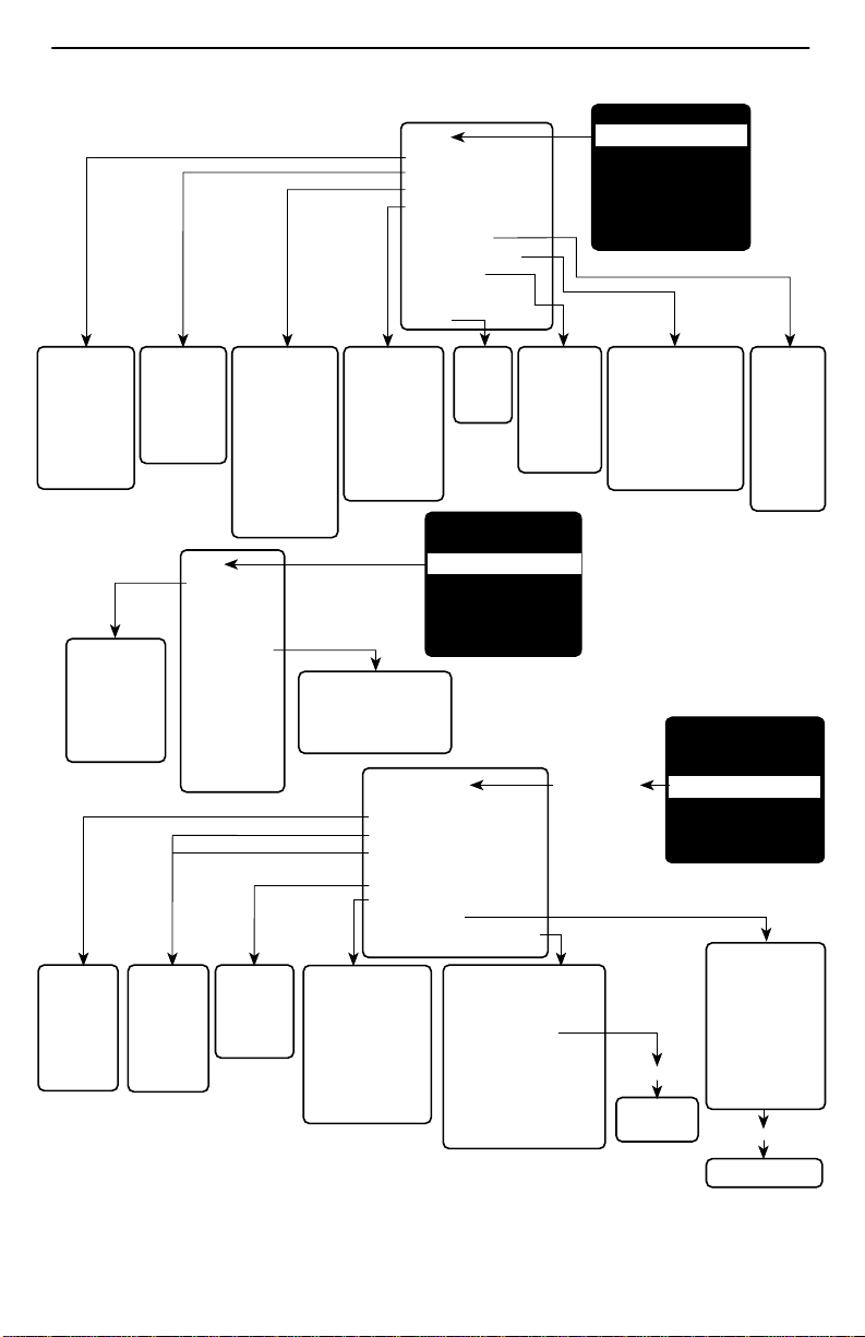
Menu Hierarchy
Status
System and Test Status
LMI Reported DLCIs
PVC Connection Status
Timeslot Assignment Status
DBM Interface Status
IP Routing Table
Performance Statistics
Trap Event Log
Display LEDs
and Control Leads
Identity
MAIN MENU
Status
Test
Configuration
Auto-Configuration
Control
Easy Install
System and
Test Status
• Self-Test Results
• Last System
Reset
• Health and
Status
• Test Status
PVC Tests
(DLCI Number)
• PVC Loopback
• Send Pattern
• Monitor Pattern
• Connectivity
• Test Call
System
• Frame Relay
and LMI
• Service
Level
Verification
• General
LMI
Reported
DLCIs
• DLCI
• Status
• CIR (bps)
Network
and
Data Ports
• Physical
• Frame Relay
• DLCI
Records
PVC Connection
Status
• Source Link,
DLCI, EDLCI
• Primary
Destination Link,
DLCI, EDLCI,
Status
• Alternate
Destination Link,
DLCI, EDLCI,
Status
Test
PVC Tests:
Network
Data Port
ISDN Call/
Physical Tests:
Network
Data Port
DSX-1
PR1
Other:
IP Ping
Lamp Test
Abort All Tests
ISDN
• Physical
• Link Profiles
• DLCI
Records
Timeslot
Assignment
Status
• Network Timeslot
Status
• Sync Data Port
Status
• DSX-1 Timeslot
Status
Physical Tests
• Local Loopbacks
• Remote Loopbacks
• Send/Monitor Pattern Tests
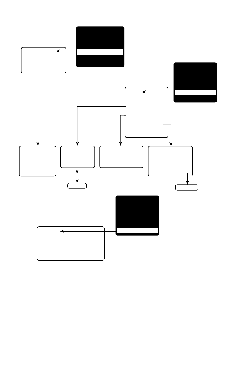
Configuration
Edit/Display
System
Network
Data Ports
DSX-1
ISDN
Time Slot Assignment
PVC Connections
Management and Communication
Autobackup Criteria
Time Slot
Assignment
• Frame Relay Network
Assignments
• Sync Data Port
Assignments
• DSX-1 to Network
Assignments
• Clear Assignments
Trap Event
Identity
Log
• System
• Number of
• NAM
Trap Events
• DBM
• Time Elasped
Since Event
• Event
MAIN MENU
Status
Test
Configuration
Auto-Configuration
Control
Easy Install
Management and
Communication Options
• Node IP
• Management PVCs
• General SNMP Management
• Telnet and FTP Session
• SNMP NMS Security
• SNMP Traps
• Communication Port
• Modem Port
Performance
Statistics
• Service Level Verification
• DLCI
• Frame Relay
• ESF Line
• DBM Call
• Clear All Statistics
Load
Configuration
from:
New or Modify
Management
PVC Entry
IP Routing
Table
• Destination
• Mask
• Gateway
• Hop
• Type
• Interface
• TTL
MAIN MENU
Status
Test
Configuration
Auto-Configuration
Control
Easy Install
PVC Connection
Table
• Source Link, DLCI,
EDLCI
• Primary Destination
Link, DLCI,
EDLCI
• Alternate Destination
Link, DLCI,
EDLCI
New or Modify
PVC Connection Entry
00-16722a
2
Page 3
Auto-Configuration
• Frame Relay Discovery Mode
• Automatic Circuit Removal
• Automatic Backup
Configuration
MAIN MENU
Status
Test
Configuration
Auto-Configuration
Control
Easy Install
Control
Modem Call Directories
System Information
Administer Logins
Change Operating Mode
Select Software Release
Select DSX/PR1 LED Source
LMI Packet Capture Utility
Disconnect Modem
Reset Device
MAIN MENU
Status
Test
Configuration
Auto-Configuration
Control
Easy Install
System Information
• Device Name
• System Name,
Location, Contact
• Date
• Time
Easy Install
• Node IP Address and Subnet Mask
• TS Access
• Create Dedicated Network Management Link
• Time Slot Assignment Screen
• Selected Network Physical Interface Options
Administer Logins
• Login ID
• Password
• Access Level
New
Login Entry
Select Software Release
• Current Release
• Alternate Release
• Switch & Reset
MAIN MENU
Status
Test
Configuration
Auto-Configuration
Control
Easy Install
LMI Packet Capture Utility
• Capture Interface
• Packet Capture Start/Stop
• Status
• Packets in Buffer
• Display LMI Trace Log
LMI Trace Log
00-16728b
3
Page 4

Configuration Option Summaries
This section summarizes the configuration options accessed when you select
Configuration from the Main Menu.
H System
H Physical (Network, Data Port, and ISDN)
H ISDN (Link Profiles)
H DSX-1
H Time Slot Assignment
— Frame Relay Network Assignments
— DSX-1 to Network Assignments
— Sync Data Port Assignments
H Frame Relay (Network and Data Port)
H DLCI Records (Network, Data Port, and ISDN)
H PVC Connections
H Management and Communication
H Auto Backup Criteria
System
Select System Options to configure options applicable to the entire system.
H Frame Relay and LMI
H Service Level Verification
H General
4
Page 5

Frame Relay and LMI
Select Frame Relay and LMI to configure the general frame relay options for the
system.
Frame Relay and LMI
Configuration Option Settings Default in [Bold]
LMI Behavior [Independent],
Port-1_Follows_Net1-FR1,
Port-2_Follows_Net1-FR1,
All_Ports_Follow_Net1-FR1
Net1-FR1_Follows_Port-1,
Net1-FR1_Follows_Port-2,
Port-1_Codependent_with_Net1-FR1,
Port-2_Codependent_with_Net1-FR1
Traffic Policing Enable, [Disable]
LMI Error Event (N2) 1, 2, [3], 4, 5, 6, 7, 8, 9, 10
LMI Clearing Event (N3) [1], 2, 3, 4, 5, 6, 7, 8, 9, 10
LMI Status Enquiry (N1) 1, 2, 3, 4, 5, [6], . . . 255
LMI Heartbeat (T1) 5, [10], 15, 20, 25, 30
LMI Inbound Heartbeat (T2) 5, 10, [15], 20, 25, 30
LMI N4 Measurement Period (T3) 5, 10, 15, [20], 25, 30
Service Level Verification
Select Service Level Verification to configure the SLV options for the system.
Service Level Verification
Configuration Option Settings Default in [Bold]
SLV Sample Interval (secs) 10–3600 [60]
SLV Delivery Ratio Enable, [Disable]
DLCI Down on SLV Timeout Enable, [Disable]
SL V Timeout Error Event
Threshold
SL V Timeout Clearing Event
Threshold
SLV Packet Size (bytes) [64]–2048
SL V Synchronization Role [Tributary], Controller, None
1, 2, [3], . . . 20
[1], 2, 3, . . . 20
5
Page 6

General
Select General to configure a timeout period and duration for user-initiated loopbacks
and pattern tests, a primary and secondary clock source for the system, and a system
alarm relay .
General
Configuration Option Settings Default in [Bold]
Test Timeout [Enable], Disable
Test Duration (min) 1–120 [10]
Primary Clock Source [Net1], DSX, Internal, DBM
Secondary Clock Source Net1, DSX, [Internal], DBM
System Alarm Relay Enable, [Disable]
Physical
Select Physical to configure the physical characteristics of each interface:
H Network
H Data Ports
H ISDN
Network
Select Network, then Physical to configure physical characteristics for the T1 network
interface.
Network
Configuration Option Settings Default in [Bold]
Line Framing Format D4, [ESF]
Line Coding Format AMI, [B8ZS]
Line Build Out (LBO) [0.0], –7.5, –15, –22.5
Bit Stuffing [62411], Disable
Transmit T iming [System], Interface
Network Initiated LLB [Enable], Disable
Network Initiated PLB [Enable], Disable
Network Initiated DCLB Disable, [V.54_&_ANSI]
ANSI Performance Report
Messages
Excessive Error Rate Threshold [10E-4], 10E-5, 10E-6, 10E-7, 10E-8, 10E-9
Circuit Identifier Text Field, [Clear]
Enable, [Disable]
6
Page 7

Data Ports
Select Data Ports, then Physical to configure physical characteristics for the port
connected to the DTE.
Data Ports
Configuration Option Settings Default in [Bold]
Port Status [Enable], Disable
Port Use (Port-2 only) [Frame Relay], Synchronous Data
For Port-1 or when Port Use is set to Frame Relay on Port-2:
Max Port Rate (Kbps)
(Port-2 only)
Invert Transmit Clock [Auto], Enable, Disable
Transmit Clock Source [Internal], External
Monitor DTR [Enable], Disable
Monitor RTS (Control) [Enable], Disable
Port (DTE) Initiated Loopback [Disable], Local, Both
When Port Use is set to Synchronous Data on Port-2:
Port Base Rate (Kbps) [Nx64], Nx56
Invert Transmit Clock [Auto], Enable, Disable
Transmit Clock Source [Internal], External
Monitor DTR [Enable], Disable
Monitor RTS (Control) [Enable], Disable
Port (DTE) Initiated Loopback [Disable], DTPLB, DCLB, Both
Invert Transmit and Receive Data Enable, [Disable]
Action on Network Yellow Alarm None, [Halt]
Network Initiated
Data Channel Loopback
[1536], 2048
[Disable], V.54, ANSI_FT1, V.54_&_ANSI
7
Page 8

ISDN
Select ISDN, then Physical to configure physical characteristics for the ISDN interface if
an ISDN DBM is installed.
The following table shows the configuration options for an ISDN BRI DBM.
ISDN BRI
Configuration Option Settings Default in [Bold]
Interface Status Enable, [Disable]
Originate or Answer [Originate], Answer
Service Profile ID 1 or 2 (SPID) [Clear] (3–20 digits)
Local Phone Number 1 or 2 [Clear] (up to 10 digits)
The following table shows the configuration options for an ISDN PRI DBM.
ISDN PRI
Configuration Option Settings Default in [Bold]
Interface Status Enable, [Disable]
Originate or Answer Originate, [Answer]
Switch Type [NI-2], ATT_4ESS, ATT_5ESS
Local Phone Number [Clear] (up to 10 digits)
Line Framing Format D4, [ESF]
Line Build Out (LBO) [0.0], –7.5, –15, –22.5
Network Initiated LLB [Enable], Disable
Network Initiated PLB [Enable], Disable
ANSI Performance Report
Messages
Excessive Error Rate Threshold [10E-4], 10E-5, 10E-6, 10E-7, 10E-8, 10E-9
Circuit Identifier Text Field, [Clear]
Enable, [Disable]
8
Page 9

ISDN Link Profiles
Select ISDN, then Link Profiles to configure the ISDN Link Profiles.
Link Profiles
Configuration Option Settings Default in [Bold]
Link Name ASCII text entry, [HQ_Site]
Link Status Auto, [Disable]
Outbound Phone Number 0–9, *, #, <space>, _, –, ), or (
Inbound Calling ID 1 or 2 0–9
Maximum Link Rate (Kbps) BRI DBM: [64], 128
PRI DBM: [64], 128, . . . 1472
DSX-1
Select DSX-1 to configure the DSX-1 interface.
DSX-1
Configuration Option Settings Default in [Bold]
Interface Status Enable, [Disable]
Line Framing Format D4, [ESF]
Line Coding Format AMI, [B8ZS]
Line Equalization [0–133], 133 –266, 266 –399, 399 –533,
533–655
Send all Ones on DSX-1 Failure [Enable], Disable
9
Page 10

Time Slot Assignment
Select Time Slot Assignment to make cross-connection assignments.
Select Frame Relay Network Assignments to assign DS0s on the T1 network
interface(s) for frame relay links.
Frame Relay-to-Network Interface Time Slot Assignment
Network Channel Settings Default in [Bold]
Time Slot Discovery [Enable], Disable
N01–N24 [Available], Assigned, FrameRly1
Select DSX-1-to-Network Assignments to assign or unassign DSX-1 timeslots to T1
network interface timeslots.
DSX-1-to-Network Interface Time Slot Assignment
Network Channel Settings Default in [Bold]
N01–N24 [Available], Assigned, DSX-1/yy
Signaling and Trunk Conditioning None, [RBS], E&M-idle, E&M-busy, FXSg-idle,
FXSg-busy, , FXS1-idle, FXS1-busy, FXSD-idle,
FXSD-busy, PLAR3idle, PLAR3busy, PLAR4idle,
PLAR4busy, DPO-idle, DPO-busy, FXOg-idle,
FXOg-busy, FXO1-idle, FXO1-busy, FXOD-idle,
FXOD-busy, DPT-idle, DPT-busy, USER-0000,
USER-0001, USER-0010, USER-0011,
USER-0100, USER-0101, USER-0110,
USER-0111, USER-1000, USER-1001,
USER-1010, USER-1011, USER-1100,
USER-1101, USER-1110, USER-1111
Select Sync Data Port Assignments to assign or unassign a synchronous data port to
the Network or DSX-1 interface timeslots.
Sync Data Port-to-Network or DSX-1 Interface Time Slot Assignment
Network or DSX-1 Channel Settings Default in [Bold]
Assign To [Net1], DSX1-1
N01–N24 (Net1)
D01–N24 (DSX1-1)
[Available], Assigned, SsPn
10
Page 11

Frame Relay
Select Frame Relay to configure the Frame Relay characteristics of the following
interfaces:
H Network
H Data Ports
Frame Relay
Configuration Option Settings Default in [Bold]
LMI Protocol lnitialize_From_Net1FR1,
Initialize_From_Interface,
Auto_On_LMI_Fail,
Standard,
Annex-A,
Annex-D
[lnitialize_From_Interface] for a data port link.
[Auto_On_LMI_Fail] for a network link.
LMI Parameters [System], Custom
When LMI Parameters is set to System:
Frame Relay DS0s Base Rate [Nx64], Nx56
When LMI Parameters is set to Custom:
Frame Relay DS0s Base Rate [Nx64], Nx56
LMI Error Event (N2) 1, 2, [3], 4, 5, 6, 7, 8, 9, 10
LMI Clearing Event (N3) [1], 2, 3, 4, 5, 6, 7, 8, 9, 10
LMI Status Enquiry (N1) 1, 2, 3, 4, 5, [6], . . . 255
LMI Heartbeat (T1) 5, [10], 15, 20, 25, 30
LMI Inbound Heartbeat (T2) 5, 10, [15], 20, 25, 30
LMI N4 Measurement Period (T3) 5, 10, 15, [20], 25, 30
11
Page 12

DLCI Records
Select DLCI Records to manually configure DLCI records for each interface. The
Auto-Configuration feature provides automatic configuration of DLCI records.
Select DLCI Records to configure the DLCI Records for the following interfaces:
H Network
H Data Port
H ISDN
The Auto-Configuration feature provides automatic DLCI record configuration.
DLCI Records for Each Interface
Configuration Option Settings Default in [Bold]
DLCI Number 16–1007
DLCI Type Standard, Multiplexed
[Standard] for DLCIs on user data ports.
[Multiplexed] for network and ISDN interfaces.
CIR (bps) 0–1536000 [64000]
Tc This field displays the committed rate
measurement interval to be used for the DLCI
based upon the displayed option settings.
Committed Burst Size Bc (Bits) [CIR], Other
Bc 0–1536000 [64000]
Excess Burst Size Be (Bits)
Be 0–1536000 [1472000]
DLCI Priority Low, Medium, [High]
Outbound Management Priority Low, [Medium], High
12
Page 13

PVC Connections
Select PVC Connections to manually configure the logical connections between the
selected interface and the data ports. The Auto-Configuration feature provides
automatic configuration of PVC connections.
PVC Connections
Configuration Option Settings Default in [Bold]
Source Link Port-n, ISDN Link Name, Net1-FR1
Source DLCI 16 –1007
Source EDLCI 0 – 62
Primary Destination Link ISDN Link Name, Net1-FR1
Primary Destination DLCI 16 –1007
Primary Destination EDLCI 0 – 62
Alternate Destination Link ISDN Link Name, Net1-FR1
Alternate Destination DLCI 16 –1007
Alternate Destination EDLCI 0–62
Management and Communication
Select Management and Communication to configure the FrameSaver unit so it can be
managed by an NMS or Telnet terminal, and to select the appropriate protocols.
H Node IP
H Management PVCs
H General SNMP Management
H Telnet and FTP Sessions
H SNMP NMS Security
H SNMP Traps
H Communication Port
H Modem Port
13
Page 14

Node IP
Select Node IP to configure support of the IP communication network.
Node IP
Configuration Option Settings Default in [Bold]
Node IP Address 001.000.000.000 – 223.255.255.255, [Clear]
Node Subnet Mask [000.000.000.000] – 255.255.255.255, Clear
Default IP Destination [None], Modem, COM, PVCname
TS Access Management Link [None], PVCname
TS Management Link
Access Level
[Level-1], Level-2, Level-3
Management PVCs
Select Management PVCs to configure a Management PVC for in-band management.
The Auto-Configuration feature provides automatic configuration of Management PVCs
on the Network interface.
Management PVCs
Configuration Option Settings Default in [Bold]
Name ASCII text entry (8 characters)
Intf IP Address [Node-IP-Address], Special (address entry:
001.000.000.000 – 223.255.255.255 )
Intf Subnet Mask [Node-Subnet-Mask], Calculate,
Special (address entry:
000.000.000.000 – 255.255.255.255)
Set DE Enable, [Disable]
Primary Link Net1-FR1, Port-n, ISDN Link Name, Clear
Primary DLCI 16–1007
Primary EDLCI 0–62
Primary Link RIP None, Standard_out, Proprietary
[Proprietary] for management links on
multiplexed DLCIs.
[Standard_out] for management links on
standard DLCIs.
Alternate Link Net1-FR1, Port-n, ISDN Link Name, Clear
Alternate DLCI 16–1007
Alternate EDLCI 0–62
14
Page 15

General SNMP Management
Select General SNMP Management to configure the FrameSaver unit so it can be
managed as an SNMP agent.
General SNMP Management
Configuration Option Settings Default in [Bold]
SNMP Management [Enable], Disable
Community Name 1 ASCII text entry, [Public], Clear
Name 1 Access Read, [Read/Write]
Community Name 2 ASCII text entry, [Clear]
Name 2 Access [Read], Read/Write
Telnet and FTP Sessions
Select Telnet and FTP Sessions to configure access to the FrameSaver unit through
Telnet or FTP, and to determine whether security will be required.
Telnet and FTP Sessions
Configuration Option Settings Default in [Bold]
Telnet Session [Enable], Disable
Telnet Login Required Enable, [Disable]
Session Access Level [Level-1], Level-2, Level-3
Inactivity Timeout [Enable], Disable
Disconnect Time (Minutes) 1–60 [10]
FTP Session [Enable], Disable
FTP Login Required Enable, [Disable]
FTP Max Receive Rate (Kbps) 1–[1536]
15
Page 16

SNMP NMS Security
Select SNMP NMS Security to configure access to the unit.
SNMP NMS Security
Configuration Option Settings Default in [Bold]
NMS IP Validation Enable, [Disable]
Number of Managers [1]–10
NMS n IP Address 001.000.000.000–223.255.255.255, [Clear]
Access Type [Read], Read/Write
SNMP Traps
Select SNMP Traps to configure desired SNMP traps and dialing out when SNMP traps
occur.
SNMP Traps
Configuration Option Settings Default in [Bold]
SNMP Traps Enable, [Disable]
Number of Trap Managers [1]– 6
NMS n IP Address 001.000.000.000–223.255.255.255, [Clear]
Initial Route Destination [AutoRoute], Modem, COM, PVCname
General Traps Disable, Warm, AuthFail, [Both]
Enterprise Specific Traps Enable, [Disable]
Link Traps Disable, Up, Down, [Both]
Link Traps Interfaces Network, DSX-1, T1s, Ports, DBM, [All]
DLCI Traps on Interfaces Network, Ports, [All]
RMON Traps [Enable], Disable
Trap Dial-Out Enable, [Disable]
Trap Disconnect [Enable], Disable
Call Retry Enable, [Disable]
Dial-Out Delay Time (Min) 1–10 [5]
Alternate Dial-Out Directory [None], 1–5
16
Page 17

Communication Port
Select Communication Port to configure the FrameSaver unit’s COM port.
Communication Port
Configuration Option Settings Default in [Bold]
Port Use [Terminal], Net Link
When Port Use is set to Terminal:
Data Rate (Kbps) 9.6, 14.4, [19.2], 28.8, 38.4, 57.6, 115.2
Character Length 7, [8]
Parity [None], Even, Odd
Stop Bits [1], 2
Ignore Control Leads [Disable], DTR
Login Required Enable, [Disable]
Port Access Level [Level-1], Level-2, Level-3
Inactivity Timeout [Enable], Disable
Disconnect Time (Minutes) 1–60 [10]
When Port Use is set to Net Link:
Data Rate (Kbps) 9.6, 14.4, [19.2], 28.8, 38.4, 57.6, 115.2
Character Length 7, [8]
Parity [None], Even, Odd
Stop Bits [1], 2
Ignore Control Leads [Disable], DTR
IP Address 001.000.000.000–223.255.255.255, [Clear]
Subnet Mask [000.000.000.000]–255.255.255.255, Clear
Link Protocol [PPP], SLIP
RIP [None], Standard_out
17
Page 18

Modem Port
Select Modem Port to configure the FrameSaver unit’s Modem port.
Modem Port
Configuration Option Settings Default in [Bold]
Port Use [Terminal], Net Link
When Port Use is set to Terminal:
Dial-In Access [Enable], Disable
Login Required Enable, [Disable]
Port Access Level [Level-1], Level-2, Level-3
Inactivity Timeout [Enable], Disable
Disconnect Time (Minutes) 1–60 [10]
When Port Use is set to Net Link:
Dial-In Access [Enable], Disable
IP Address 001.000.000.000–223.255.255.255, [Clear]
Subnet Mask [000.000.000.000]–255.255.255.255, Clear
Link Protocol [PPP], SLIP
Alternate IP Address 001.000.000.000 –223.255.255.255, [Clear]
Alternate Subnet Mask [000.000.000.000]–255.255.255.255, Clear
RIP [None], Proprietary , Standard_out
Auto Backup Criteria
Select Auto Backup Criteria to control when automatic backup will take place.
Auto Backup Criteria
Configuration Option Settings Default in [Bold]
Auto Backup Enable, [Disable]
When Auto Backup Allowed [Always], Restrict
Backup Allowed From Monday–Sunday, [00:00]–23:00
Backup Allowed To Monday–Sunday, 00:00 –[24:00]
18
Page 19

Warranty, Sales, Service, and Training Information
Contact your local sales representative, service representative, or distributor directly for
any help needed. For additional information concerning warranty , sales, service, repair,
installation, documentation, training, distributor locations, or Paradyne worldwide office
locations, use one of the following methods:
H Internet: Visit the Paradyne World Wide Web site at www.paradyne.com.
(Be sure to register your warranty at www.paradyne.com/warranty.)
H Telephone: Call our automated system to receive current information via fax or to
speak with a company representative.
— Within the U.S.A., call 1-800-870-2221
— Outside the U.S.A., call 1-727-530-2340
Document Feedback
We welcome your comments and suggestions about this document. Please mail them
to Technical Publications, Paradyne Corporation, 8545 126th Ave. N., Largo, FL 33773,
or send e-mail to userdoc@paradyne.com. Include the number and title of this
document in your correspondence. Please include your name and phone number if you
are willing to provide additional clarification.
Trademarks
FrameSaver is a registered trademark of Paradyne Corporation. All other products and
services mentioned herein are the trademarks, service marks, registered trademarks,
or registered service marks of their respective owners.
Patent Notification
FrameSaver SL V products are protected by U.S. Patents: 5,550,700 and 5,654,966.
Other U.S. patents pending.
Copyright E 2000 Paradyne Corporation. Printed in U.S.A.
19
 Loading...