

Paradyne Fan Tray Assembly 8820-S3-900 Installation Instructions Manual

8820-A2-GZ48-00 January 2005 1
Replacement Fan Tray Assembly for the
8820 Broadband Loop Carrier
Model 8820-S3-900
Installation Instructions
Document Number 8820-A2-GZ48-00
January 2005
Fan Tray Assembly
The fan tray assembly is a dedicated cooling device installed in the chassis of the
8820 Broadband Loop Carrier (BLC) to provide forced–air cooling of the chassis.
The fans, located at the top of the BLC chassis, draw cooling air upwards from the
bottom of the chassis, through the circuit cards or card cage, forcing the air out the
opening, located at the top rear of the chassis.
The fan tray assembly consists of six fans, a metal bracket, and a printed wiring
board (PWB) with a press-fit connector and five status LEDs. Each fan provides a
sense wire that indicates the status of the fan. The sense wires are connected to
the backplane via the fan tray’s PWB and its connector.
The rated airflow is 900 cfm (based on 6 fans at 150 cfm each) at zero back
pressure.
The fan tray is powered by –48 or –60 VDC from the backplane of the 8820 BLC.
Nominal power consumption is less than 100 watts.
An LED is on the fan tray so that if a fan failure occurs, a signal is sent to the SCP
card or MCP card and the yellow Fan ALARM LED on the chassis lights. Removal
of the fan tray also causes the SCP card or MCP card to sense an alarm.
The fan tray assembly weighs 10 lbs (22 kg). It is secured by two fan-locking
brackets located on the right and left front of the assembly.
2 January 2005 8820-A2-GZ48-00
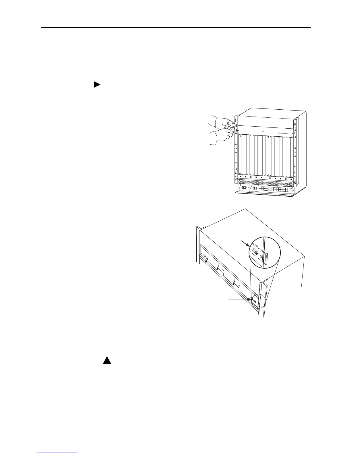
Removing the Existing Fan Tray Assembly
You will need a Phillips screwdriver to remove the vent cover and fan tray.
Procedure
To remove the existing fan tray assembly:
1. Remove three screws from the fan
cover plate, and then remove the
cover plate from the chassis, taking
care not to damage the LED
protruding through the cover plate.
2. Loosen (but do not remove)
the two screws on each
locking bracket, and use
them to slide both locking
brackets toward the middle
of the front panel until the
ends clear the slots in the
side plates.
NOTE:
There are two cutouts in the front face of the fan tray labeled PULL AREA.
This is where you place your fingers to pull the fan tray out of the chassis.
WARNING:
A MECHANICAL HAZARD EXISTS DUE TO ROTATING FAN BLADES. KEEP
HANDS AND FINGERS AWAY FROM FAN BLADES DURING REMOVAL OF
FAN TRAY. USE ONLY THE DESIGNATED PULL AREAS TO DISENGAGE
THE FAN TRAY.
00-16792
ALARMS
Major Minor
FanB
A
POWER
S
E
R
IA
L
S
M
C
M
C
L
O
C
K
A
A
L
A
R
M
2
4
6
8
1
0
1
2
1
4
1
6
1
8
1
35
7
9
1
1
1
3
1
5
1
7
L
A
N
/W
A
N
S
L
O
T
B
C
L
O
C
K
B
A
S
E
R
IA
L
M
C
C
A
C
A
L
A
R
M
48V RTN
48V NEG
P
O
W
E
R
E
N
T
R
Y
M
O
D
U
L
E
L
E
F
T
U
N
IT
:
L
I
N
E
A
R
I
G
H
T
U
N
I
T
:
L
I
N
E
B
W
A
R
N
IN
G
!
P
O
W
E
R
M
U
S
T
B
E
D
IS
C
O
N
N
E
C
T
E
D
A
T
T
H
E
S
O
U
R
C
E
B
E
F
O
R
E
R
E
M
O
V
IN
G
O
R
IN
S
T
A
L
L
I
N
G
T
H
IS
P
W
R
E
N
T
R
Y
M
O
D
U
L
E
48V RTN
48V NEG
P
O
W
E
R
E
N
T
R
Y
M
O
D
U
L
E
L
E
F
T
U
N
IT
:
L
I
N
E
A
R
I
G
H
T
U
N
I
T
:
L
I
N
E
B
W
A
R
N
IN
G
!
P
O
W
E
R
M
U
S
T
B
E
D
IS
C
O
N
N
E
C
T
E
D
A
T
T
H
E
S
O
U
R
C
E
B
E
F
O
R
E
R
E
M
O
V
I
N
G
O
R
IN
S
T
A
L
L
IN
G
T
H
IS
P
W
R
E
N
T
R
Y
M
O
D
U
L
E
00-16793
CAUTION!
D
O
N
O
T
PL
A
C
E FIN
G
E
R
S
U
N
D
E
R
T
H
E FA
N
TR
A
Y
U
S
E
T
HE
D
ES
IG
N
A
TE
D
P
U
LL
AR
EAS
CAUTION!
D
O
N
O
T
P
L
A
C
E
F
I
N
G
E
R
S
U
N
D
E
R
T
H
E
F
A
N
T
R
A
Y
U
S
E
T
H
E
D
E
S
I
G
N
A
T
E
D
P
U
L
L
A
R
E
A
S
PULL
AREA
PULL
A
REA
Loosen Screws
Locking
Bracket
!
 Loading...