

Page 1

COMSPHERE
DUALFLOW DSU
QUICK REFERENCE
Document No. 3615-A2-GL10-00
Page 2

Copyright 1999 Paradyne Corporation.
All rights reserved.
Printed in U.S.A.
Notice
This publication is protected by federal copyright law. No part of this publication may be
copied or distributed, transmitted, transcribed, stored in a retrieval system, or translated
into any human or computer language in any form or by any means, electronic,
mechanical, magnetic, manual or otherwise, or disclosed to third parties without the
express written permission of Paradyne Corporation, 8545 126th Ave. N., Largo,
FL 33773.
Paradyne Corporation makes no representation or warranties with respect to the
contents hereof and specifically disclaims any implied warranties of merchantability or
fitness for a particular purpose. Further, Paradyne Corporation reserves the right to
revise this publication and to make changes from time to time in the contents hereof
without obligation of Paradyne Corporation to notify any person of such revision or
changes.
Changes and enhancements to the product and to the information herein will be
documented and issued as a new release to this manual.
Warranty, Sales, and Service Information
Contact your local sales representative, service representative, or distributor directly for
any help needed. For additional information concerning warranty, sales, service, repair,
installation, documentation, training, distributor locations, or Paradyne worldwide office
locations, use one of the following methods:
Via the Internet: Visit the Paradyne World Wide Web site at
http://www.paradyne.com
Via Telephone: Call our automated call system to receive current information via
fax or to speak with a company representative.
— Within the U.S.A., call 1-800-870-2221
— Outside the U.S.A, call 1-727-530-2340
Document Feedback
We welcome your comments and suggestions about this document. Please mail them
to Technical Publications, Paradyne Corporation, 8545 126th Ave. N., Largo, FL 33773,
or send e-mail to userdoc@eng.paradyne.com. Include the number and title of this
document in your correspondence. Please include your name and phone number if you
are willing to provide additional clarification.
Trademarks
All products and services mentioned herein are the trademarks, service marks,
registered trademarks or registered service marks of their respective owners.
Page 3

496-15149
TM
1
COMSPHERE DualFlow DSU
Quick Reference
Document Number 3615-A2-GL10-00
January 1999
Product Documentation on the World Wide Web
We provide complete product documentation online. This lets you search the
documentation for specific topics and print only what you need, reducing the waste of
surplus printing. It also helps us maintain competitive prices for our products.
Complete documentation for this product is available at www.paradyne.com.
Select
Service & Support → Technical Manuals → Subrate Digital Access Devices
.
Then select the following document:
3615-A2-GB20
COMSPHERE DualFlow Data Service Units User’s Guide
To request a paper copy of a Paradyne document:
Within the U.S.A., call 1-800-PARADYNE (1-800-727-2396)
Outside the U.S.A., call 1-727-530-8623
Precautions
Before installing your DSU, read the
Important Safety Instructions
on page 19.
!
HANDLING PRECAUTIONS FOR STATIC-SENSITIVE DEVICES
This product is designed to protect sensitive components from
damage due to electrostatic discharge (ESD) during normal
operation. When performing installation procedures,
however, take proper static control precautions to
prevent damage to equipment. If you are not sure
of the proper static control precautions, contact
your nearest sales or service representative.
Page 4
2
How to Change Hardware Straps
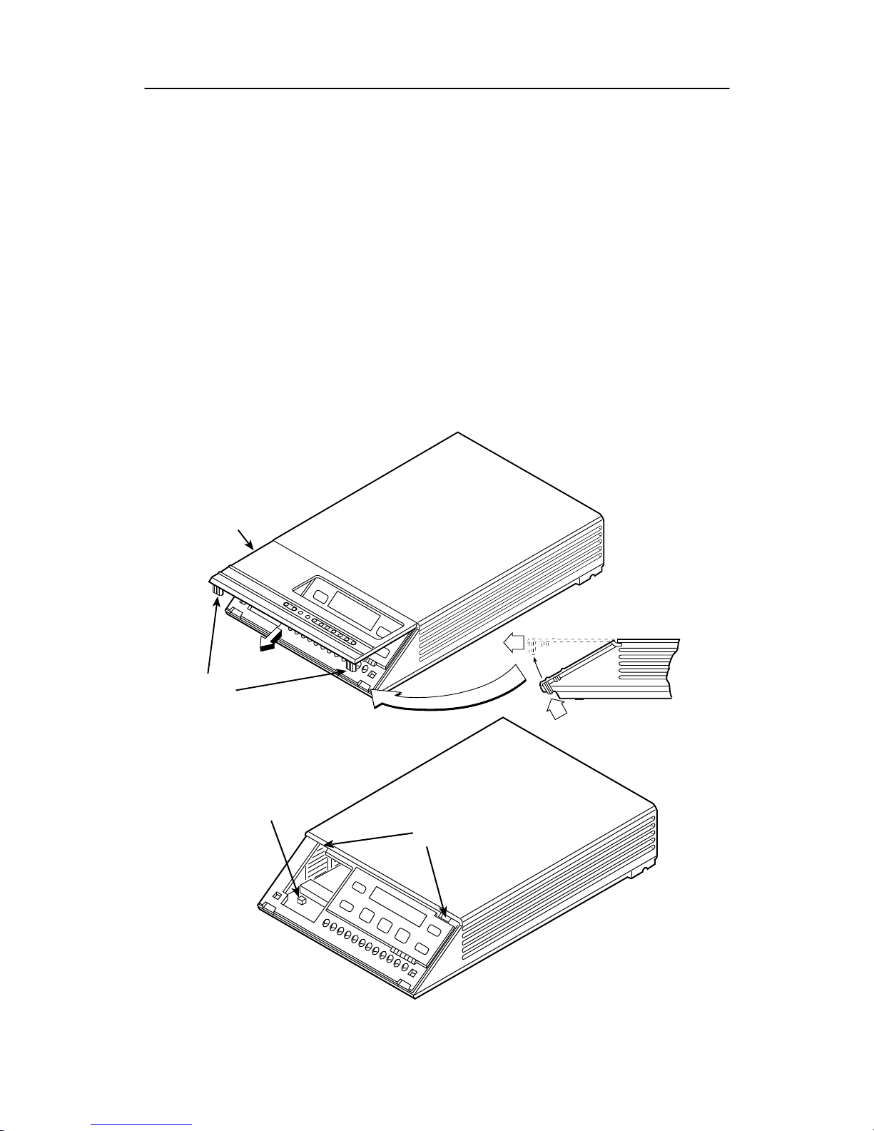
The Model 3615 DSU has a switch located behind its diagnostic control panel (DCP).
This switch contains two straps, one that controls the permissive or programmable
connection for the DBM, and one that controls the frame-to-signal grounds. Table 1
shows the DSU’s switch settings. Use the following procedure to set the switches.
Procedure
1. With your thumbs under the edge of the front bezel, firmly press upward to lift the
bezel from the tabs securing it in place.
2. Swing the front bezel up and set the bezel aside.
3. Refer to Table 1 to determine which switch needs to be changed. Then, using a
small instrument, carefully change the position of the switch.
4. Reinsert the front bezel’s hinge tabs into position and swing the bezel down. Snap
the bezel back into place.
496-14499-01
SWITCH 1
HINGE T AB
LOCA TIONS
FRONT BEZEL
COMSPHERE 3615
SNAP
TABS
Model 3615 DSU Hardware Switch Location
Page 5

3
Table 1. Model 3615 DSU Switch Settings
Switch Position Switch Setting Function
ON
(default)
Permissive V.32 DBM transmit output level
of –9 dBm
S1-1
Off Programmable V.32 DBM transmit level
between –12 dBm and 0 dBm
ON Frame ground (FG) connected to signal
ground (SG)
S1-2
Off
(default)
FG connected to SG through 100 ohm
resistor
ON is toward the rear as you face the front of the DSU.
Off is toward the front.
Where to Place the DSU
The DSU must be placed within 6 feet of a dedicated grounded ac outlet that is
protected by a circuit breaker.
The distance between the DSU and its DTE must be within EIA-232-D/V.24 limits, or
V.35 limits if operating the DSU at speeds greater than 19.2 kbps.
For the EIA-232 connector, the typical maximum distance is 50 feet at speeds less
than or equal to 19.2 kbps. If a longer distance is needed, use high quality, low
capacitance cable and ensure that the effective shunt capacitance of the circuit
(measured at the DSU and including the capacitance of the cable and the DTE)
does not exceed 2500 picofarads, as specified in EIA-232-D.
For the V.35 connector, the maximum distance recommended between the DSU
and the DTE is nominally 1000 feet.
Allow 1 to 2 feet of clearance around the DSU for access and cable connections during
installation.
Page 6
4
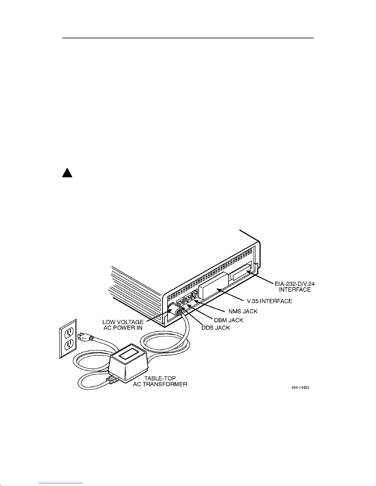
Installing the DSU
Before installing the DSU, label the circuit breaker that protects the ac wall outlet, and
make sure that it is set to ON. Then proceed with the installation.
Procedure
1. Place the DSU in its planned location. Make sure the ventilation slots are not
blocked.
2. At the rear of the DSU, insert the ac transformer, circular plug into the interface
labeled POWER.
3. Plug the ac transformer’s 3-prong plug into the ac wall outlet.
!
WARNING:
Only use the power transformer designed for the Model 3615 DSU. Using
other transformers may result in personal injury or damage to the equipment.
Model 3615 DSU Electrical Connection
Page 7

5
Power-Up Routine
When power is applied, the DSU:
H Runs a Device Test on itself and the DBM.
During the tests, all indicators on the DCP light briefly and the message Power-Up
Tests appears on the liquid crystal display (LCD).
H Displays the results of each test momentarily as Pass, Fail, or Abrt.
(
Abrt indicates
that the Device Test was aborted because a network loopback was in progress
during the power-up procedure.)
These tests take about 20 seconds to complete.
If the DSU or DBM fails this test, follow these steps.
" Procedure
1. Press the key to return to the top-level menu.
2. Select Local (F1 key).
3. Press the
key to scroll the
Confg
(Configuration) branch into view.
4. Press the function key directly below Confg.
5. Press the F1 key to select Opts (Configuration Options).
The
Load from
screen appears.
6. Press the
key to bring the factory-loaded unit configurations into view, and
select the appropriate configuration. Select:
— SyBC (Synchronous Backup for a Control DSU) for a control when the router
controls backup.
— SyBT (Synchronous Backup for a Tributary DSU) for a tributary when the
router controls backup.
— DiDg (Dial Diagnostics) for asynchronous router-management data to be sent
over the EIA-232 port via the DBM connection and user data over the V.35 port
via the DDS connection.
7. Press the F1 key to SAVE the selected configuration.
The
Save to
screen appears.
8. Save the selected configuration to Activ (F1 key).
9. Press the
key to return to the top-level menu, then select Local again.
10. Select Test (F3).
The
Run Test on
screen appears.
11. Select the device that Failed: the DSU or DBM.
12. Press the F2 key to run the Device Test again.
The device should pass.
13. Should the device fail, contact your service representative.
Page 8
6
Connecting to the Network
The DSU provides three interfaces. One jack connects the DSU to the 6700 or 6800
Series NMS, one connects the DSU to the dial (or public switched telephone network –
PSTN) network, and one connects the DSU to the DDS network. Follow the appropriate
procedure when making your network connections.
Connecting to the NMS
A 3600 Hubbing Device is required to connect the control DSU to the 6700 or 6800
Series NMS. When connected to the NMS, the DSU can be controlled and configured
from the NMS rather than from the DCP alone.
Procedure
1. Plug the 4-pin modular plug of the 3600 Hubbing Device into the DSU jack labeled
CC/DC.
2. Plug one end of an M6BJ cable into the hubbing device jack labeled CC IN/DC
OUT.
3. Plug the other end of the 6-pin M6BJ cable into the 6-pin end of the 873A adapter.
4. Plug the D-type end of the 873A adapter into the appropriate 6700 or 6800 Series
NMS jack.
Refer to your COMSPHERE 6700 or 6800 Series NMS documentation to control and
configure the DSU from the NMS.
496-14576a
NMS NETWORK
CONNECTION
CC/DC
HUBBING
DEVICE
LOW VOLTAGE
AC POWER IN
TO
NMS (873A)
3000HUBBING DEVICE
MODEL #3000-F3-300
Model 3615 DSU NMS Connection
Page 9

7
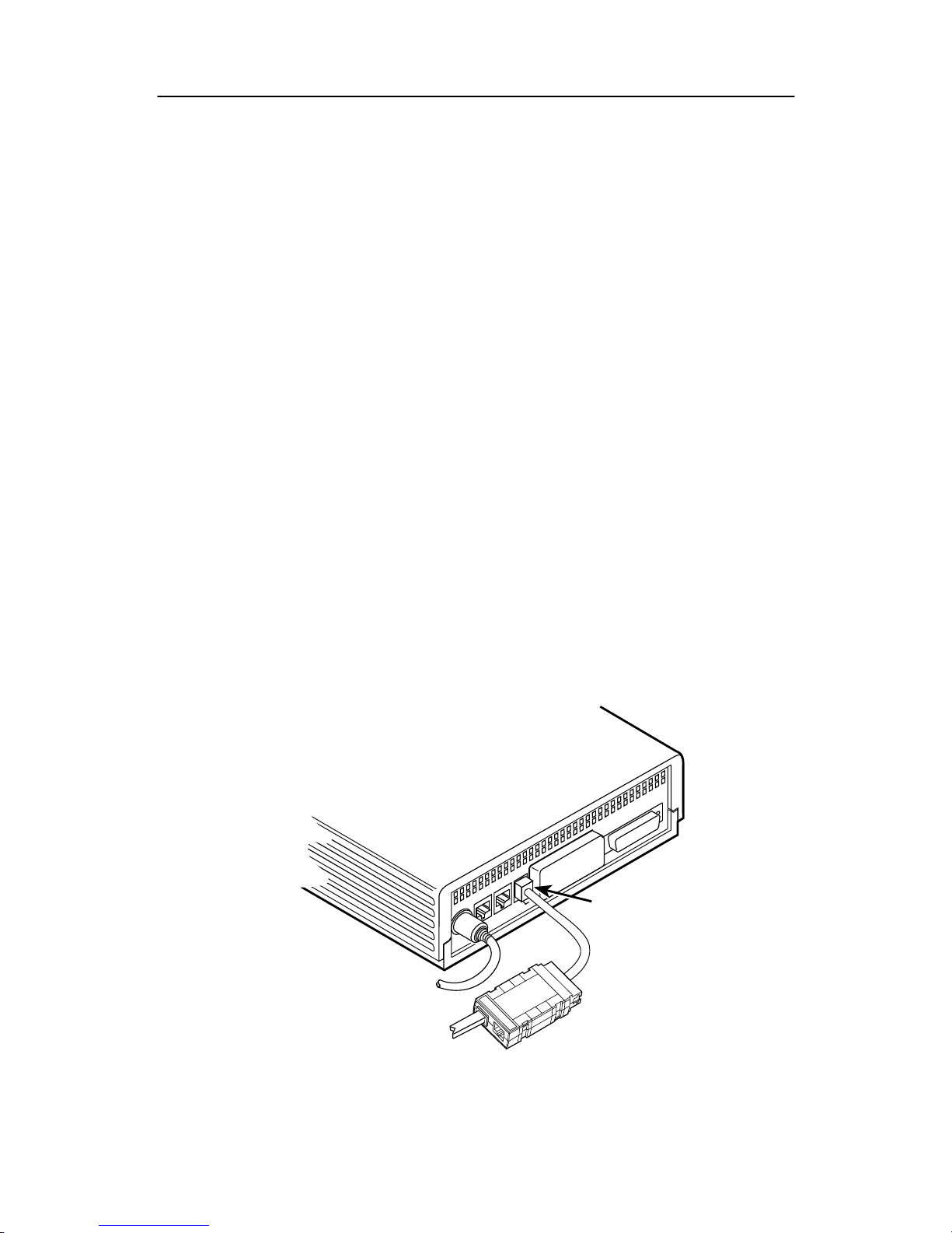
Connecting to the Dial (or PSTN) Network
If your DSU is equipped with a V.32 DBM, follow these steps to connect it to the dial
network.
Procedure
1. Plug either end of the dial (analog) interface cable into the DSU jack labeled
BACKUP.
— For permissive
service, use a telephone cord with an 6-pin modular RJ11C
plug.
— For programmable
service, use a telephone cord with an 8-pin RJ45S plug.
2. Plug the other end of the cable into the modular jack provided by the telephone
company, USOC RJ11C (permissive) or USOC RJ45S (programmable).
3. If your site has programmable service, verify that the DSU’s hardware strap S1-1 is
switched to the Off position.
Model 3615 DSU Dial (PSTN) Network Connection
Page 10

8
Connecting to the Switched 56 kbps Network
NOTE:
Before connecting the DSU to the Switched 56 kbps network, ensure that approved
primary protectors have been installed on the circuit in accordance with Article 800
of the National Electric Code, NFPA 70, in the United States and Section 60 of the
Canadian Electric Code, Part 1, in Canada.
If the DSU is equipped with a 4-wire Switched 56 DBM, an 8-pin cable is provided; if a
2-wire Switched 56 DBM, a 6-pin cable is provided.
!
WARNING:
Do not insert the 2-wire Switched 56 kbps plug into an RJ11C jack. This type
of jack is intended for analog public switched telephone network (PSTN)
devices. Doing so may cause equipment damage and harm to the telephone
network.
To make a physical connection to the Switched 56 kbps network, follow these steps.
Procedure
1. Plug either end of the Switched 56 kbps network interface cable into the DSU jack
labeled BACKUP.
— For the 2-wire Switched 56 DBM, use the 6-pin cable.
— For the 4-wire Switched 56 DBM, use the 8-pin cable.
2. Plug the other end of the cable into the modular jack provided for the
Switched 56 kbps network connection.
Model 3615 DSU Switched 56 kbps Network Connection
Page 11

9
Connecting to the DDS (or LADS) Network
NOTE:
Before connecting the DSU to the DDS network, ensure that approved primary
protectors have been installed on the circuit in accordance with Article 800 of the
National Electric Code, NFPA 70, in the United States and Section 60 of the
Canadian Electric Code, Part 1, in Canada.
Follow these steps to connect the DSU to the network.
Procedure
1. Plug the DDS network interface cable into the DSU jack labeled LINE.
— U.S.
– select either end of the cable
— Canada – select the 8-pin end
2. Plug the other end of the cable into the modular jack (USOC RJ48S) provided by
the circuit provider.
If the remote DSU is also connected to the network, the DSU’s green OK indicator lights
and the Alrm indicator goes off. The Health and Status screen no longer displays a
No Signal
message.
If connecting the DSU to a LADS network, there are distance limitations that govern the
use of DSUs on the network. Table 2 summarizes these limitations.
Model 3615 DSU DDS (LADS) Network Connection
Page 12

10
Table 2. LADS Connection Distances
Data Rate
Wire Gauge (AWG)
Data Rate
(kbps)
19 22 24 26
2.4 20.0 mi
(32.2 km)
16.6 mi
(26.7 km)
12.7 mi
(20.5 km)
9.4 mi
(15.1 km)
4.8 19.4 mi
(31.2 km)
12.7 mi
(20.5 km)
9.6 mi
(15.4 km)
7.1 mi
(11.5 km)
9.6 15.2 mi
(24.5 km)
9.7 mi
(15.6 km)
7.3 mi
(11.7 km)
5.6 mi
(9.0 km)
19.2
1
11.8 mi
(19.0 km)
7.5 mi
(12.1 km)
5.7 mi
(9.2 km)
4.2 mi
(6.8 km)
38.4 11.2 mi
(18.0 km)
6.5 mi
(10.5 km)
4.6 mi
(7.4 km)
3.2 mi
(5.1 km)
56 9.2 mi
(14.8 km)
5.4 mi
(8.7 km)
3.8 mi
6.2 km)
2.8 mi
(4.5 km)
64 9.2 mi
(14.8 km)
5.4 mi
(8.7 km)
3.8 mi
(6.2 km)
2.8 mi
4.5 km)
1
Power level is –10 dBm.
Connecting the DSU to a Router
The DualFlow DSU transmits user data through its V.35 interface and diagnostic or user
data through its EIA-232-D/V.24 interface. Cabling is based upon the preset
configuration (SyBC, SyBT, or DiDg) selected in the Opts subbranch (Config branch).
Follow this procedure to connect the DSU to a router.
Procedure
1. Connect the plug end of the router’s V.35 cable to the DSU’s V.35 connector.
Tighten the two holding screws.
2. Connect the other end of the router’s V.35 cable to the router’s primary serial port.
Tighten any holding screws.
Page 13

99-16248
EIA-232-D/V.24
Interface
V.35 Interface
DiDg Configuration:
To Router
Console Port
(Router-Management
Data)
DSU
Low V oltage
AC Power In
To Router
Primary Serial Port
(User Data)
To NMS
(Control Device
Only)
CC
SyBC OR SyBT
Configuration:
To Router
Secondary Serial Port
(Backup Or Overflow
Data)
3000HUBBING DEVICE
MODEL #3000-F3-300
11
3. Connect the plug end of the router’s EIA-232 cable to the DSU’s EIA-232-D/V.24
connector.
Tighten any holding screws.
4. Connect the other end of the router’s EIA-232 cable to the router:
— If the DSU is to be configured using the SyBC
or
SyBT configuration, connect
to the router’s secondary serial port.
— If the DSU is to be configured using the
DiDg configuration, connect to the
router’s console port.
Tighten any holding screws.
Router Connection
Page 14

12
Addressing the Unit
A unique address must be assigned to each control and tributary DSU in your network.
You can assign an address within the range of 1 through 255.
Do not assign the number 192 as a network address. This number is reserved as a
broadcast address.
The numbers 191 and 255 cannot be assigned to a DSU that has a DBM. However,
addresses can be assigned in any order; they do not have to be sequential.
It is recommended that only
odd-numbered addresses be assigned to DSUs so that
even-numbered addresses are reserved for DBMs
.
The DBM requires a separate address, which is automatically assigned by the DSU.
The address assigned a DBM is the DSU’s address, plus 1 (for example, if the DSU’s
address is 1, the assigned DBM address will be 2).
Tributary DSU Addressing
Tributary DSU addresses are user-definable. The control DSU accesses its tributary via
an active backup connection by specifying the tributary’s address.
The 6700 or 6800 Series NMS accesses the DSU via its network address. To access a
tributary DSU, the NMS first addresses the control, then the tributary . An address issued
from the NMS takes the format of control channel/control DBM network
address/tributary network address. This is called link-level network addressing.
Verifying Operation and Testing Connections
After installing and configuring the circuit (including control and tributary DSUs, the DDS
network, the DBMs and their dial connections), perform the following series of tests from
the control DSU to verify network operation (using either the DCP or NMS).
Next, test the tributary DBM for dial tone, and verify that the DSU can place and receive
calls.
Addressing Example
Page 15

13
Verifying DBM Operation
A backup connection must be established to verify that the switched network is
functioning. Then, perform the Digital Test by selecting the DBM path.
Procedure
1. Select Local (F1).
2. Select Bckup (F2).
3. Select Dial to establish a dialed call to the tributary.
Refer to Chapter 4 of the User’s Guide for the procedure for entering telephone
numbers.
4. Press the
key, then select Cnnct to switch to the dial circuit.
5. Press the
key twice.
6. Select Test (F3).
7. Select DBM (F2).
8. Select DT (F3).
9. Select Start (F1).
10. Select the amount of time you want the test to run in hours: minutes: seconds
(hh:mm:ss).
— Press the
or key to move the blinking cursor to the digit to be
changed.
— Press the F1 ( ) key to increment the digit (1 through 9).
— Press the F2 ( ) key to decrement the digit.
11. Select Enter (F3).
Please wait
appears as the DBM runs the test.
12. When
Command Complete
appears, press the key.
13. Select Displ (F1) to display the results of the test.
14. Press the
key to scroll through the test results.
Page 16

14
Verifying Network Addresses
Access the DSU’s identity (ID) subbranch for the tributary DSU to ensure that the DSU
is properly addressed.
Procedure
1. Select Remot (Remote branch).
2. Enter the tributary’s network address.
3. Select Stat (Status branch).
4. Press the
key until ID appears.
5. Select ID.
6. Press the
key until Network Addr appears.
7. Verify that the correct address has been entered.
Verifying the Network
Perform a Health and Status check on the DDS circuit to ensure that the network is
functioning.
Procedure
1. Select Local (F1).
2. Select Stat (F1).
3. Select H/S (F1).
4. Select Devic (F1).
5. Press the
key to return to the top-level menu.
6. Select Local (F1).
7. Select Bckup (F2).
8. Select DrBU to drop the backup call.
No error messages should appear.
Page 17

15
Configuration Options
Configuration options are accessed from the Configuration branch of the front panel
menu.
In the following tables, factory defaults are shown in boldface type.
Key to symbols:
D Switched 56 DBM only
DD
2-wire Switched 56 DBM only
{ V.32 DBM only
{{ Only if Call Setup set to Pswrd
{{{ Only if Diag Type set to NonD
} Only if Primary Core set to Yes
}}Only at the Control
Hardware Straps Value
DDD Interface D
Permissive, Programmable
Frame Ground/Signal Ground Connected, Disconnected
V .35 Test Mode Indication Enabled, Disabled
EIA-232-D T est Mode Indication Enabled, Disabled
–48 Vdc Alarm Monitoring Enabled, Disabled
–48 Vdc Alarm Monitoring via NMS
Adapter Cable
Enabled, Disabled
DSU Value
Rate(Kbps) 64CC, 64L, 56, 38.4, 19.2, 9.6, 4.8, 2.4
TxClkSource Int, RXC, Ext, DDS
19.2 PowrLvl +6, 0, –10
64KScramblng On, Off
64KLatchLpbk On, Off
V .54 Lpbk Enab, Disab
Page 18

16
DSU Port (V.35) Value
DTE Port V .35
RTS Cntrl FrcOn, DTE
CTS Cntrl Std, =RTS, Delay, FrcOn
AntiStream Disab, 1–100 (sec)
LSD Lead Std, Delay, FrcOn
DSR FrcOn Enab, Disab
SystemStat Enab, Disab
DSR on Tst Enab, Disab
Circ Assur Enab, Disab
RespondRDL Enab, Disab
LL by DTE Enab, Disab
Bilat Lpbk Enab, Disab
DTR Alarm Enab, Disab
DBM Value
Rate(Kbps) 14.4, 12.0, 9.6, 4.8, 2.4
PrtSp(Kbps) 56 (default for Switched 56 DBM), 48, 38.4, 32, 28.8, 19.2, 18.8,
18.0, 16.8, 14.4, 12.0, 9.6 (default for V.32 DBM), 9.2, 8.4, 7.2, 4.8,
4.4, 4.0, 2.4, 2.0, 1.2, Disab
TxClkSource Int (default for Control), RXC (default for Tributary), Ext
CarrLossDisc Yes, No
Auto Retrain Yes, No
Single Rate Y es, No
AutoAnswer Enab, Disab
Call Setup None, Pswrd, Cllbk, Alarm
RxPwd (Up to 10 digits)
TxPwd (Up to 10 digits)
Dial Test Enab, Disab
Primary Core Y es, No
DTRCallCon Orig (default for SyBC), Ansr (default for DiDg andSyBT), Disab
Page 19

17
DBM
(continued)
Value
EchoCancel D
Enab, Disab
Remot DBM DD
2-wire, 4-wire
Msg Clamp Enab, Disab
DBM Port (232) Value
DTE Port 232, V.35}
RTS Cntrl FrcOn (default for DiDg), DTE (default for SyBC and SyBT)
CTS Cntrl Std, =RTS, FrcOn
AntiStream Disab, (1 to 100 sec)
LSD Lead Std, FrcOn
DSR FrcOn Enab, Disab
DSR on Tst Enab, Disab
RespondRDL Enab, Disab
RL by DTE Enab, Disab
Bilat Lpbk Enab, Disab
Ext Leads ExtLd, Rate, RPowr
CCN by EL Enab, Disab
DTR Alarm Enab, Disab
Async→Sync Enab (default for DiDg), Disab (default for SyBC and SyBT)
AsyncBit/Char 6, 7, 8, 9, 10
Stop Bits 1, 2
Overspeed 1.0, 2.3
Page 20

18
Diagnostic DBM Value
Diag Type NonD, Disr, None
2nd Ch(bps){{{ 100, 400, 800, 1200, 1600
Diagnostic General Value
Position Cntrl (default for SyBC), Trib (default for DiDg and SyBT)
RemoteDiag V.54 {, Enhan
Link Delay }} 0s, 1s, 2s, 5s, 10s, 20s, 50s
Packet Delay }} 0s, 1s, 2s, 5s
Backup Value
Auto Bckup Enab, Disab
Backup Dir 1–10
BckupOnCMI Enab, Disab
AutoRestor Enab, Disab
NtwkTimOut
0:20 (default for a Control DSU), 01:00 (default for a Tributary DSU).
(1 to 30 min)
RestorTimOut 5m, (1 to 60 min)
TriesT imeOut 15m , (1 to 60 min)
MultiCall Enab, Disab
Page 21

19
!
Important Safety Instructions
1. Read and follow all warning notices and instructions marked on the product or
included in the manual.
2. This product is intended to be used with a 3-wire grounding type plug – a plug
which has a grounding pin. This is a safety feature. Equipment grounding is vital to
ensure safe operation. Do not defeat the purpose of the grounding type plug by
modifying the plug or using an adapter.
Prior to installation, use an outlet tester or a voltmeter to check the ac receptacle
for the presence of earth ground. If the receptacle is not properly grounded, the
installation must not continue until a qualified electrician has corrected the problem.
If a 3-wire grounding type power source is not available, consult a qualified
electrician to determine another method of grounding the equipment.
3. Slots and openings in the cabinet are provided for ventilation. To ensure reliable
operation of the product and to protect it from overheating, these slots and
openings must not be blocked or covered.
4. Do not allow anything to rest on the power cord and do not locate the product
where persons will walk on the power cord.
5. Do not attempt to service this product yourself, as opening or removing covers may
expose you to dangerous high voltage points or other risks. Refer all servicing to
qualified service personnel.
6. General purpose cables are provided with this product. Special cables, which may
be required by the regulatory inspection authority for the installation site, are the
responsibility of the customer.
7. When installed in the final configuration, the product must comply with the
applicable Safety Standards and regulatory requirements of the country in which it
is installed. If necessary, consult with the appropriate regulatory agencies and
inspection authorities to ensure compliance.
8. A rare phenomenon can create a voltage potential between the earth grounds of
two or more buildings. If products installed in separate buildings are
interconnected, the voltage potential may cause a hazardous condition. Consult a
qualified electrical consultant to determine whether or not this phenomenon exists
and, if necessary, implement corrective action prior to interconnecting the products.
9. In addition, if the equipment is to be used with telecommunications circuits, take the
following precautions:
— Never install telephone wiring during a lightning storm.
— Never install telephone jacks in wet locations unless the jack is specifically
designed for wet locations.
— Never touch uninsulated telephone wires or terminals unless the telephone line
has been disconnected at the network interface.
— Use caution when installing or modifying telephone lines.
— Avoid using a telephone (other than a cordless type) during an electrical storm.
There may be a remote risk of electric shock from lightning.
— Do not use the telephone to report a gas leak in the vicinity of the leak.
Page 22

20
Notices
!
WARNING:
THIS EQUIPMENT HAS BEEN TESTED AND FOUND TO COMPLY WITH THE LIMITS FOR
A CLASS A DIGITAL DEVICE, PURSUANT TO PART 15 OF THE FCC RULES. THESE
LIMITS ARE DESIGNED TO PROVIDE REASONABLE PROTECTION AGAINST
HARMFUL INTERFERENCE WHEN THE EQUIPMENT IS OPERATED IN A COMMERCIAL
ENVIRONMENT. THIS EQUIPMENT GENERATES, USES, AND CAN RADIATE RADIO
FREQUENCY ENERGY AND, IF NOT INSTALLED AND USED IN ACCORDANCE WITH
THE INSTRUCTION MANUAL, MAY CAUSE HARMFUL INTERFERENCE TO RADIO
COMMUNICA TIONS. OPERATION OF THIS EQUIPMENT IN A RESIDENTIAL AREA IS
LIKELY TO CAUSE HARMFUL INTERFERENCE IN WHICH CASE THE USER WILL BE
REQUIRED TO CORRECT THE INTERFERENCE AT HIS OWN EXPENSE. THE
AUTHORITY TO OPERATE THIS EQUIPMENT IS CONDITIONED BY THE
REQUIREMENTS THAT NO MODIFICATIONS WILL BE MADE TO THE EQUIPMENT
UNLESS THE CHANGES OR MODIFICATIONS ARE EXPRESSLY APPROVED BY
P ARADYNE.
!
WARNING:
TO USERS OF DIGITAL APPARATUS IN CANADA:
THE DIGITAL APPARATUS DOES NOT EXCEED THE CLASS A LIMITS FOR RADIO
NOISE EMISSIONS FROM DIGITAL APPARATUS SET OUT IN THE RADIO
INTERFERENCE REGULATIONS OF THE CANADIAN DEPARTMENT OF
COMMUNICATIONS.
LE PRESÉNT APPAREIL NUMÉRIQUE N’ÉMET PAS DE BRUITS RADIOÉLECTRIQUES
DÉP ASSANT LES LIMITES APPLICABLES AUX APPAREILS NUMÉRIQUES DE LA
CLASSE A PRESCRITES DANS LE RÈGLEMENT SUR LE BROUILLAGE
RADIOÉLECTRIQUE ÉDICTÉ PAR LE MINISTÈRE DES COMMUNICATIONS DU
CANADA.
Page 23

21
Government Requirements
Certain governments require that instructions pertaining to connection to the telephone
network be included in the installation and operation manual. Specific instructions are
listed in the following sections.
Notice to Users of the Digital Data Service
This equipment complies with Part 68 of the FCC rules. On the bottom of the equipment
is a label or silk-screened text that contains, among other information, the FCC
registration number and Ringer Equivalence Number (REN) for this equipment. If
requested, please provide this information to your telephone company.
The REN is useful to determine the quantity of devices you may connect to your
telephone line and still have all of those devices ring when your number is called. In
most, but not all areas, the sum of the RENs of all devices should not exceed 5. To be
certain of the number of devices you may connect to your line, as determined by the
REN, you should call your local telephone company to ascertain the maximum REN for
your calling area.
If your DSU causes harm to the telephone network, the telephone company may
discontinue your service temporarily. If possible, they will notify you in advance. But if
advance notice is not practical, you will be notified as soon as possible. You will be
advised of your right to file a complaint with the FCC.
Your telephone company may make changes in its facilities, equipment, operations, or
procedures that could affect the proper operation of your equipment. If so, you will be
given advance notice so as to give you an opportunity to maintain uninterrupted
service.
The DBM cannot be used on public coin-operated telephone service provided by the
telephone company. Connection to party-line service is subject to state tariffs. (Contact
the state public utility commission, public service commission, or corporation
commission for information.)
No repairs may be performed by the user. Should you experience difficulty with this
equipment, refer to
Warranty, Sales, and Service Information
inside the cover of this
document.
Page 24

22
For Digital Data Service (DDS) installations, inform the local telephone company of the
appropriate network channel interface code for the service you desire.
DDS
Interface Code Data Rate (bps)
04DU5-24 2400
04DU5-48 4800
04DU5-96 9600
04DU5-19 19,200
04DU5-56 56,000
04DU5-64 64,000
The DDS Service Order Number is 6.0Y. The jack configurations required are RJ48S for
the Model 3615 DSU and RJ48T for the Model 3616. With an RJ48T configuration, you
must specify the number of data lines you require. Refer to the
Technical Specifications
section of Chapter 1 of the User’s Guide for V.32 DBM jack information.
After the telephone company has installed the requested jack, you can connect the
DSU with the appropriate cable (provided). An FCC-compliant telephone cord and
modular plug is provided with this equipment. This equipment is designed to be
connected to the telephone network or premises wiring using a compatible modular jack
that is Part 68 compliant.
*3615–A2–GL10–00*
 Loading...