

Page 1

COMSPHERE
392xP
MODELS 3920P
LUS MODEMS
LUS
AND 3921PLUS
TECHNICAL REFERENCE MANUAL
Document No. 3920-A2-GH30-41
February 2002
Page 2

COMSPHERE 392xPlus Modems
COMSPHERE
392xPlus Modems
Models 3920Plus and 3921Plus
Technical Reference Manual
3920-A2-GH30-41
6th Edition (February 2002)
Changes and enhancements to the product and to the information herein will be documented and issued as a new release or
a Firmware Update Description document to this manual.
For the Model 3920Plus standalone modems, the Universal Service Order Code (USOC) for Permissive mode is RJ11C.
The Canadian equivalent to RJ11C is CA11A. For the 3921Plus carrier-mounted modems, the USOC for Permissive mode
is RJ21X. The Canadian equivalent to RJ21X is CA21A.
For regulatory approval, refer to the product labeling or contact your local representative.
Warranty, Sales, and Service Information
Contact your local sales representative, service representative, or distributor directly for any help needed. For additional
information concerning warranty, sales, service, repair, installation, documentation, training, distributor locations, or
Paradyne worldwide office locations, use one of the following methods:
H Via the Internet: Visit the Paradyne W orld Wide Web site at http://www.paradyne.com
H Via Telephone: Call our automated call system to receive current information via fax or to speak with a company
representative.
— Within the U.S.A., call 1-800-870-2221
— Outside the U.S.A., call 1-727-530-2340
Trademarks
All products and services mentioned herein are the trademarks, service marks, registered trademarks or registered service
marks of their respective owners.
Printed on recycled paper
COPYRIGHT E 1998, 2002 Paradyne Corporation. All rights reserved.
This publication is protected by federal copyright law. No part of this publication may be copied or distributed, transmitted, transcribed, stored in a retrieval system,
or translated into any human or computer language in any form or by any means, electronic, mechanical, magnetic, manual or otherwise, or disclosed to third parties
without the express written permission of Paradyne Corporation, 8545 126th Avenue North, P.O. Box 2826, Largo, Florida 33779-2826.
Paradyne Corporation makes no representation or warranties with respect to the contents hereof and specifically disclaims any implied warranties of merchantability
or fitness for a particular purpose. Further, Paradyne Corporation reserves the right to revise this publication and to make changes from time to time in the contents
hereof without obligation of Paradyne Corporation to notify any person of such revision or changes.
A February 2002 3920-A2-GH30-41
Page 3

Important Safety Instructions
1. Read and follow all warning notices and instructions marked on the product or included in the
manual.
2. Some models are provided with a three-wire grounding type plug – a plug which has a
grounding pin. This is a safety feature. Equipment grounding is vital to ensure safe operation.
Do not defeat the purpose of the grounding type plug by modifying the plug or using an
adapter.
Prior to installation, use an outlet tester or a voltmeter to check the ac receptacle for the
presence of earth ground. If the receptacle is not properly grounded, the installation must not
continue until a qualified electrician has corrected the problem.
If a three-wire grounding type power source is not available, consult a qualified electrician to
determine another method of grounding the equipment.
3. Slots and openings in the cabinet are provided for ventilation. T o ensure reliable operation of
the product and to protect it from overheating, these slots and openings must not be blocked
or covered.
4. Do not allow anything to rest on the power cord and do not locate the product where persons
will walk on the power cord.
Safety Instructions
5. Do not attempt to service this product yourself, as opening or removing covers may expose
you to dangerous high voltage points or other risks. Refer all servicing to qualified service
personnel.
6. General purpose cables are provided with this product. Special cables, which may be required
by the regulatory inspection authority for the installation site, are the responsibility of the
customer.
7. When installed in the final configuration, the product must comply with the applicable Safety
Standards and regulatory requirements of the country in which it is installed. If necessary,
consult with the appropriate regulatory agencies and inspection authorities to ensure
compliance.
8. A rare phenomenon can create a voltage potential between the earth grounds of two or more
buildings. If products installed in separate buildings are interconnected, the voltage potential
may cause a hazardous condition. Consult a qualified electrical consultant to determine
whether or not this phenomenon exists and, if necessary, implement corrective action prior to
interconnecting the products.
9. In addition, if the equipment is to be used with telecommunications circuits, take the
following precautions:
– Never install telephone wiring during a lightning storm.
– Never install telephone jacks in wet locations unless the jack is specifically designed for
wet locations.
– Never touch uninsulated telephone wires or terminals unless the telephone line has been
disconnected at the network interface.
– Use caution when installing or modifying telephone lines.
– Avoid using a telephone (other than a cordless type) during an electrical storm.
There may be a remote risk of electric shock from lightning.
– Do not use the telephone to report a gas leak in the vicinity of the leak.
B3920-A2-GH30-40 October 1998
Page 4

COMSPHERE 392xPlus Modems
Notices
WARNING
THIS EQUIPMENT HAS BEEN TESTED AND FOUND TO COMPL Y WITH THE LIMITS FOR A CLASS A DIGITAL DEVICE,
PURSUANT TO PART 15 OF THE FCC RULES. THESE LIMITS ARE DESIGNED TO PROVIDE REASONABLE
PROTECTION AGAINST HARMFUL INTERFERENCE WHEN THE EQUIPMENT IS OPERATED IN A COMMERCIAL
ENVIRONMENT. THIS EQUIPMENT GENERATES, USES, AND CAN RADIATE RADIO FREQUENCY ENERGY AND, IF
NOT INSTALLED AND USED IN ACCORDANCE WITH THE INSTRUCTION MANUAL, MAY CAUSE HARMFUL
INTERFERENCE TO RADIO COMMUNICATIONS. OPERATION OF THIS EQUIPMENT IN A RESIDENTIAL AREA IS
LIKELY TO CAUSE HARMFUL INTERFERENCE IN WHICH CASE THE USER WILL BE REQUIRED TO CORRECT THE
INTERFERENCE AT HIS OWN EXPENSE.
THE AUTHORITY TO OPERATE THIS EQUIPMENT IS CONDITIONED BY THE REQUIREMENTS THAT NO
MODIFICATIONS WILL BE MADE T O THE EQUIPMENT UNLESS THE CHANGES OR MODIFICA TIONS ARE EXPRESSL Y
APPROVED BY PARADYNE.
WARNING
TO USERS OF DIGITAL APPARATUS IN CANADA:
THIS CLASS [A] DIGITAL APPARATUS MEETS ALL REQUIREMENTS OF THE CANADIAN INTERFACE-CAUSING
EQUIPMENT REGULATIONS.
CET APPAREIL NUMERIQUE DE LA CLASSE [A] RESPECTE TOUTES LES EXIGENCES DU REGLEMENT SUR LE
MATERIEL BROUILLEUR DU CANADA.
C October 1998 3920-A2-GH30-40
Page 5

Table of Contents
Preface
Objectives and Reader Assumptions vii. . . . . . . . . . . . . . . . . . . . . . . . .
How to Use This Manual vii. . . . . . . . . . . . . . . . . . . . . . . . . . . . . . . . . .
Related Documents viii. . . . . . . . . . . . . . . . . . . . . . . . . . . . . . . . . . . . . .
1. Introduction
Overview 1-1. . . . . . . . . . . . . . . . . . . . . . . . . . . . . . . . . . . . . . . . . . . . . .
COMSPHERE 392xPlus Models 1-2. . . . . . . . . . . . . . . . . . . . . . . . . . .
392xPlus Operational Modes 1-6. . . . . . . . . . . . . . . . . . . . . . . . . . . . . . .
392xPlus Modem Features 1-7. . . . . . . . . . . . . . . . . . . . . . . . . . . . . . . .
392xPlus Singleport Modem Features 1-7. . . . . . . . . . . . . . . . . . . . . . . .
392xPlus Multiport Modem Features 1-7. . . . . . . . . . . . . . . . . . . . . . . .
Applications 1-8. . . . . . . . . . . . . . . . . . . . . . . . . . . . . . . . . . . . . . . . . . . .
Government Requirements and Equipment Return 1-10. . . . . . . . . . . . . .
T echnical Specifications 1-13. . . . . . . . . . . . . . . . . . . . . . . . . . . . . . . . . .
2. Modem Installation
Overview 2-1. . . . . . . . . . . . . . . . . . . . . . . . . . . . . . . . . . . . . . . . . . . . . .
392xPlus Modem Package 2-1. . . . . . . . . . . . . . . . . . . . . . . . . . . . . . . . .
Model 3920Plus Modem Installation 2-3. . . . . . . . . . . . . . . . . . . . . . . . .
Connecting Cables to the Model 3920Plus Modem 2-3. . . . . . . . . . . . .
Removing and Replacing the Model 3920Plus Modem 2-8. . . . . . . . . .
Model 3921Plus Modem Installation 2-8. . . . . . . . . . . . . . . . . . . . . . . . .
Removing the Model 3921Plus Modem 2-13. . . . . . . . . . . . . . . . . . . . . .
392xPlus Modem Power-Up 2-13. . . . . . . . . . . . . . . . . . . . . . . . . . . . . . .
Selecting Factory Configuration Options 2-13. . . . . . . . . . . . . . . . . . . . .
3. DCP Operation
Overview 3-1. . . . . . . . . . . . . . . . . . . . . . . . . . . . . . . . . . . . . . . . . . . . . .
Diagnostic Control Panels 3-1. . . . . . . . . . . . . . . . . . . . . . . . . . . . . . . . .
Status Indicators 3-2. . . . . . . . . . . . . . . . . . . . . . . . . . . . . . . . . . . . . . . . .
Diagnostic Control Panel Operation 3-6. . . . . . . . . . . . . . . . . . . . . . . . .
Menu Structure 3-8. . . . . . . . . . . . . . . . . . . . . . . . . . . . . . . . . . . . . . . . . .
i3920-A2-GH30-40 October 1998
Page 6

COMSPHERE 392xPlus Modems
4. Status Branch
5. Configure Branch
6. Poll List Branch
7. Control Branch
Status Branch 4-1. . . . . . . . . . . . . . . . . . . . . . . . . . . . . . . . . . . . . . . . . . .
Overview 5-1. . . . . . . . . . . . . . . . . . . . . . . . . . . . . . . . . . . . . . . . . . . . . .
Configure Branch 5-3. . . . . . . . . . . . . . . . . . . . . . . . . . . . . . . . . . . . . . . .
Configuration T ables 5-8. . . . . . . . . . . . . . . . . . . . . . . . . . . . . . . . . . . . .
Multiport Mode 5-8. . . . . . . . . . . . . . . . . . . . . . . . . . . . . . . . . . . . . . . . .
Singleport Mode 5-35. . . . . . . . . . . . . . . . . . . . . . . . . . . . . . . . . . . . . . . . .
Poll List Branch 6-1. . . . . . . . . . . . . . . . . . . . . . . . . . . . . . . . . . . . . . . . .
Control Branch 7-1. . . . . . . . . . . . . . . . . . . . . . . . . . . . . . . . . . . . . . . . . .
8. Test Branch
T est Branch 8-1. . . . . . . . . . . . . . . . . . . . . . . . . . . . . . . . . . . . . . . . . . . .
9. Sub-Network Health and Status Branch
Sub-Network Health and Status Branch 9-1. . . . . . . . . . . . . . . . . . . . . .
10. Call Setup Branch
Call Setup Branch 10-1. . . . . . . . . . . . . . . . . . . . . . . . . . . . . . . . . . . . . . .
11. Talk/Data Branch
T alk/Data Branch 11-1. . . . . . . . . . . . . . . . . . . . . . . . . . . . . . . . . . . . . . . .
12. Dial Access Security
Overview 12-1. . . . . . . . . . . . . . . . . . . . . . . . . . . . . . . . . . . . . . . . . . . . . .
Security Branch 12-5. . . . . . . . . . . . . . . . . . . . . . . . . . . . . . . . . . . . . . . . .
Security Configuration Options 12-14. . . . . . . . . . . . . . . . . . . . . . . . . . . . .
Security Password Entry T echniques 12-16. . . . . . . . . . . . . . . . . . . . . . . . .
Database T able Examples 12-18. . . . . . . . . . . . . . . . . . . . . . . . . . . . . . . . .
13. Remote Branch
ii October 1998 3920-A2-GH30-40
Remote Branch 13-1. . . . . . . . . . . . . . . . . . . . . . . . . . . . . . . . . . . . . . . . . .
Page 7

14. AT Command Set and S-Registers
Overview 14-1. . . . . . . . . . . . . . . . . . . . . . . . . . . . . . . . . . . . . . . . . . . . . .
Command and Data Modes 14-1. . . . . . . . . . . . . . . . . . . . . . . . . . . . . . . .
Command Guidelines 14-2. . . . . . . . . . . . . . . . . . . . . . . . . . . . . . . . . . . . .
AT Command List 14-5. . . . . . . . . . . . . . . . . . . . . . . . . . . . . . . . . . . . . . .
S-Register List 14-16. . . . . . . . . . . . . . . . . . . . . . . . . . . . . . . . . . . . . . . . . .
Appendices
A. Menu Tree A-1. . . . . . . . . . . . . . . . . . . . . . . . . . . . . . . . . . . . . . . . .
B. Troubleshooting B-1. . . . . . . . . . . . . . . . . . . . . . . . . . . . . . . . . . . . .
C. Pin Assignments C-1. . . . . . . . . . . . . . . . . . . . . . . . . . . . . . . . . . . . .
D. ITU-T V.25bis Dialing Commands and Responses D-1. . . . . . . . . .
E. ASCII Character T able E-1. . . . . . . . . . . . . . . . . . . . . . . . . . . . . . . .
F. Default Configuration Options F-1. . . . . . . . . . . . . . . . . . . . . . . . .
G. Sample Configurations G-1. . . . . . . . . . . . . . . . . . . . . . . . . . . . . . . .
H. Synchronous Data Compression H-1. . . . . . . . . . . . . . . . . . . . . . . .
I. Equipment List I-1. . . . . . . . . . . . . . . . . . . . . . . . . . . . . . . . . . . . . .
Table of Contents
Glossary
Index
iii3920-A2-GH30-40 October 1998
Page 8

COMSPHERE 392xPlus Modems
Figure Page
1-1 3920-A2 Standalone Modem 1-2. . . . . . . . . . . . . . . . . . . . . . . . . . . . . . . . . . . . . . . . . . .
1-2 3920-A1 Standalone Singleport and Multiport Modems 1-3. . . . . . . . . . . . . . . . . . . . . .
1-3 Model 3921Plus Singleport Modem 1-4. . . . . . . . . . . . . . . . . . . . . . . . . . . . . . . . . . . . .
1-4 Model 3921Plus Multiport Modem 1-5. . . . . . . . . . . . . . . . . . . . . . . . . . . . . . . . . . . . . .
2-1 Model 3920Plus Singleport (3920-A2-xxx) Back Panel and Power Supply 2-4. . . . . . .
2-2 Model 3920Plus Multiport Back Panel and Power Supply 2-5. . . . . . . . . . . . . . . . . . . .
2-3 Model 3921Plus Back Connector Plates 2-9. . . . . . . . . . . . . . . . . . . . . . . . . . . . . . . . . .
2-4 Installing the Model 3921Plus Modem 2-10. . . . . . . . . . . . . . . . . . . . . . . . . . . . . . . . . . .
2-5 Circuit Pack Lock 2-12. . . . . . . . . . . . . . . . . . . . . . . . . . . . . . . . . . . . . . . . . . . . . . . . . . .
3-1 Model 3920Plus DCP 3-2. . . . . . . . . . . . . . . . . . . . . . . . . . . . . . . . . . . . . . . . . . . . . . . .
3-2 Optional SDCP and Model 3921Plus Faceplates 3-3. . . . . . . . . . . . . . . . . . . . . . . . . . .
3-3 392xPlus LCD and Keypad 3-6. . . . . . . . . . . . . . . . . . . . . . . . . . . . . . . . . . . . . . . . . . . .
5-1 DCP Configuration Process 5-2. . . . . . . . . . . . . . . . . . . . . . . . . . . . . . . . . . . . . . . . . . . .
8-1 Local Analog Loopback 8-4. . . . . . . . . . . . . . . . . . . . . . . . . . . . . . . . . . . . . . . . . . . . . . .
8-2 Remote Digital Loopback 8-5. . . . . . . . . . . . . . . . . . . . . . . . . . . . . . . . . . . . . . . . . . . . .
8-3 Local Digital Loopback 8-7. . . . . . . . . . . . . . . . . . . . . . . . . . . . . . . . . . . . . . . . . . . . . . .
8-4 Pattern T est and Local Analog Loopback Test 8-8. . . . . . . . . . . . . . . . . . . . . . . . . . . . .
8-5 Pattern T est and Digital Loopback Test 8-9. . . . . . . . . . . . . . . . . . . . . . . . . . . . . . . . . . .
8-6 End-to-End Pattern T est 8-9. . . . . . . . . . . . . . . . . . . . . . . . . . . . . . . . . . . . . . . . . . . . . . .
10-1 Dial Backup 10-5. . . . . . . . . . . . . . . . . . . . . . . . . . . . . . . . . . . . . . . . . . . . . . . . . . . . . . . .
C-1 VF Pin Orientation C-3. . . . . . . . . . . . . . . . . . . . . . . . . . . . . . . . . . . . . . . . . . . . . . . . . . .
C-2 Wiring Diagram — “Y” Cable for External Telephone C-4. . . . . . . . . . . . . . . . . . . . . . .
C-3 Wiring Diagram — 8-Position to 6-Position Crossover Cable C-5. . . . . . . . . . . . . . . . .
C-4 Wiring Diagram — 25-Pin Crossover Cable C-6. . . . . . . . . . . . . . . . . . . . . . . . . . . . . . .
G-1 Sample Configuration — Point-to-Point G-2. . . . . . . . . . . . . . . . . . . . . . . . . . . . . . . . . .
G-2 Sample Configuration — Extended Point-to-Point G-4. . . . . . . . . . . . . . . . . . . . . . . . . .
G-3 Sample Configuration — Extended Multipoint G-6. . . . . . . . . . . . . . . . . . . . . . . . . . . . .
G-4 Sample Configuration — Point-to-Point with Automatic Dial Backup G-8. . . . . . . . . .
G-5 Sample Configuration — Point-to-Point with Network Management G-10. . . . . . . . . . .
G-6 Sample Configuration — Carrier with Network Management G-12. . . . . . . . . . . . . . . . .
G-7 Sample Configuration — Extended Diagnostics G-14. . . . . . . . . . . . . . . . . . . . . . . . . . . .
G-8 Sample Configuration — Digital Bridge G-16. . . . . . . . . . . . . . . . . . . . . . . . . . . . . . . . . .
G-9 Sample Configuration — Point-to-Point MSD G-18. . . . . . . . . . . . . . . . . . . . . . . . . . . . .
G-10 Sample Configuration — Multipoint MSD G-20. . . . . . . . . . . . . . . . . . . . . . . . . . . . . . . .
H-1 Sample DTE Exchange of Data via Synchronous Protocol and SDC H-1. . . . . . . . . . . .
H-2 Synchronous Data Compression H-2. . . . . . . . . . . . . . . . . . . . . . . . . . . . . . . . . . . . . . . .
H-3 Synchronous Data Format H-2. . . . . . . . . . . . . . . . . . . . . . . . . . . . . . . . . . . . . . . . . . . . .
H-4 Clocks at the DTE–DCE Interface H-4. . . . . . . . . . . . . . . . . . . . . . . . . . . . . . . . . . . . . . .
List of Figures
iv October 1998 3920-A2-GH30-40
Page 9

Table of Contents
List of Tables
Table Page
1-1 392xPlus Operational Modes 1-6. . . . . . . . . . . . . . . . . . . . . . . . . . . . . . . . . . . . . . . . . . .
1-2 T echnical Specifications for 392xPlus Modems 1-13. . . . . . . . . . . . . . . . . . . . . . . . . . . .
3-1 392xPlus DCP LEDs 3-4. . . . . . . . . . . . . . . . . . . . . . . . . . . . . . . . . . . . . . . . . . . . . . . . .
3-2 SDCP LEDs 3-5. . . . . . . . . . . . . . . . . . . . . . . . . . . . . . . . . . . . . . . . . . . . . . . . . . . . . . . .
3-3 T op-Level Menu Status 3-10. . . . . . . . . . . . . . . . . . . . . . . . . . . . . . . . . . . . . . . . . . . . . . .
3-4 Common Operational Messages 3-13. . . . . . . . . . . . . . . . . . . . . . . . . . . . . . . . . . . . . . . .
3-5 Dial Access Security Messages 3-13. . . . . . . . . . . . . . . . . . . . . . . . . . . . . . . . . . . . . . . . .
4-1 Health and Status Messages 4-3. . . . . . . . . . . . . . . . . . . . . . . . . . . . . . . . . . . . . . . . . . . .
4-2 SDC Performance Measurements 4-11. . . . . . . . . . . . . . . . . . . . . . . . . . . . . . . . . . . . . . .
4-3 Backup Status Screens 4-14. . . . . . . . . . . . . . . . . . . . . . . . . . . . . . . . . . . . . . . . . . . . . . . .
5-1 DTE Interface Configuration Options — Multiport Mode 5-10. . . . . . . . . . . . . . . . . . . .
5-2 Line Dialer Configuration Options — Multiport Mode 5-19. . . . . . . . . . . . . . . . . . . . . .
5-3 Dial Line Configuration Options — Multiport Mode 5-22. . . . . . . . . . . . . . . . . . . . . . . .
5-4 Leased Line Configuration Options — Multiport Mode 5-25. . . . . . . . . . . . . . . . . . . . . .
5-5 T est Configuration Options — Multiport Mode 5-30. . . . . . . . . . . . . . . . . . . . . . . . . . . .
5-6 Miscellaneous Configuration Options — Multiport Mode 5-31. . . . . . . . . . . . . . . . . . . .
5-7 DTE Interface Configuration Options — Singleport Mode 5-37. . . . . . . . . . . . . . . . . . .
5-8 DTE Dialer Configuration Options — Singleport Mode 5-45. . . . . . . . . . . . . . . . . . . . . .
5-9 Line Dialer Configuration Options — Singleport Mode 5-49. . . . . . . . . . . . . . . . . . . . . .
5-10 Dial Line Configuration Options — Singleport Mode 5-53. . . . . . . . . . . . . . . . . . . . . . .
5-11 Leased Line Configuration Options — Singleport Mode 5-57. . . . . . . . . . . . . . . . . . . . .
5-12 V.42/MNP/Buffer Configuration Options — Singleport Mode 5-64. . . . . . . . . . . . . . . . .
5-13 Test Configuration Options — Singleport Mode 5-71. . . . . . . . . . . . . . . . . . . . . . . . . . . .
5-14 Miscellaneous Configuration Options — Singleport Mode 5-73. . . . . . . . . . . . . . . . . . .
7-1 Valid Ranges for VF Thresholds 7-20. . . . . . . . . . . . . . . . . . . . . . . . . . . . . . . . . . . . . . . .
10-1 Valid Dial Command Modifiers 10-9. . . . . . . . . . . . . . . . . . . . . . . . . . . . . . . . . . . . . . . . .
12-1 Edit Password Table Group Options 12-9. . . . . . . . . . . . . . . . . . . . . . . . . . . . . . . . . . . . .
12-2 Set Answer Security Group Options 12-10. . . . . . . . . . . . . . . . . . . . . . . . . . . . . . . . . . . . .
12-3 Set Originate Security Group Options 12-11. . . . . . . . . . . . . . . . . . . . . . . . . . . . . . . . . . . .
12-4 Security Configuration Options 12-14. . . . . . . . . . . . . . . . . . . . . . . . . . . . . . . . . . . . . . . . .
12-5 Security Database Table Using VF-Side Passwords 12-18. . . . . . . . . . . . . . . . . . . . . . . . .
12-6 Security Database Table Using DTE-Side Passwords 12-18. . . . . . . . . . . . . . . . . . . . . . . .
12-7 Security Database Table Using Both VF-Side and DTE-Side Passwords 12-19. . . . . . . . .
14-1 Result Codes 14-3. . . . . . . . . . . . . . . . . . . . . . . . . . . . . . . . . . . . . . . . . . . . . . . . . . . . . . .
14-2 392xPlus AT Commands 14-6. . . . . . . . . . . . . . . . . . . . . . . . . . . . . . . . . . . . . . . . . . . . . .
14-3 392xPlus S-Registers 14-17. . . . . . . . . . . . . . . . . . . . . . . . . . . . . . . . . . . . . . . . . . . . . . . . .
v3920-A2-GH30-40 October 1998
Page 10

COMSPHERE 392xPlus Modems
Table Page
B-1 Modem Health B-1. . . . . . . . . . . . . . . . . . . . . . . . . . . . . . . . . . . . . . . . . . . . . . . . . . . . . .
B-2 Leased-Line Operation B-2. . . . . . . . . . . . . . . . . . . . . . . . . . . . . . . . . . . . . . . . . . . . . . . .
B-3 Dial Backup Operation B-2. . . . . . . . . . . . . . . . . . . . . . . . . . . . . . . . . . . . . . . . . . . . . . .
B-4 Modem — DTE Connection B-3. . . . . . . . . . . . . . . . . . . . . . . . . . . . . . . . . . . . . . . . . . .
B-5 Modem — VF Connection B-4. . . . . . . . . . . . . . . . . . . . . . . . . . . . . . . . . . . . . . . . . . . . .
B-6 Online Operation B-5. . . . . . . . . . . . . . . . . . . . . . . . . . . . . . . . . . . . . . . . . . . . . . . . . . . .
B-7 Misc Operation B-5. . . . . . . . . . . . . . . . . . . . . . . . . . . . . . . . . . . . . . . . . . . . . . . . . . . . . .
B-8 Mux Operation B-6. . . . . . . . . . . . . . . . . . . . . . . . . . . . . . . . . . . . . . . . . . . . . . . . . . . . . .
C-1 EIA-232-D Pin Assignments C-2. . . . . . . . . . . . . . . . . . . . . . . . . . . . . . . . . . . . . . . . . . .
C-2 VF Connector Pin Assignments C-3. . . . . . . . . . . . . . . . . . . . . . . . . . . . . . . . . . . . . . . . .
D-1 V.25bis Commands D-6. . . . . . . . . . . . . . . . . . . . . . . . . . . . . . . . . . . . . . . . . . . . . . . . . .
D-2 V.25bis Response Messages D-7. . . . . . . . . . . . . . . . . . . . . . . . . . . . . . . . . . . . . . . . . . . .
E-1 ASCII Characters E-1. . . . . . . . . . . . . . . . . . . . . . . . . . . . . . . . . . . . . . . . . . . . . . . . . . . .
F-1 Factory Default Configuration Options F-2. . . . . . . . . . . . . . . . . . . . . . . . . . . . . . . . . . .
H-1 SDC Negotiation Configuration Scenarios H-7. . . . . . . . . . . . . . . . . . . . . . . . . . . . . . . .
vi October 1998 3920-A2-GH30-40
Page 11

Preface
Objectives and Reader Assumptions
This manual describes how to install and operate the COMSPHERE Model 3920Plus standalone
and Model 3921Plus carrier-mounted modems. Users of this manual must have a basic
understanding of modems and their operation.
How to Use This Manual
Chapter 1 provides technical specifications, information about the four 392xPlus models, the
modem features, and the government requirements for using these modems.
Chapter 2 provides instructions for installing the 392xPlus modems.
Chapter 3 provides the information required to operate the Model 3920Plus using the diagnostic
control panel and the Model 3921Plus using the COMSPHERE 3000 Series Carrier’s shared
diagnostic control panel (SDCP).
Chapter 4 provides information about the Status branch of the DCP menu.
Chapter 5 provides the information required to set configuration options in the 392xPlus modems
using the modem’s diagnostic control panel.
Chapter 6 provides information about the Poll List branch of the DCP menu.
Chapter 7 provides information about the Control branch of the DCP menu.
Chapter 8 provides information about the T est branch of the DCP menu.
Chapter 9 provides information about the Sub-Network Health and Status branch of the DCP
menu.
Chapter 10 provides information about the Call Setup branch of the DCP menu.
Chapter 11 provides information about the Talk/Data branch of the DCP menu.
Chapter 12 provides instructions for using the Dial Access Security feature.
Chapter 13 provides information about the Remote branch of the DCP menu.
Chapter 14 provides instructions for using AT commands and S-Registers.
Appendix A provides a menu tree for the 392xPlus modems.
Appendix B provides instructions for performing diagnostic tests when data communication
problems occur.
vii3920-A2-GH30-40 October 1998
Page 12

COMSPHERE 392xPlus Modems
Appendix C provides EIA-232-D and VF TELCO pin assignments.
Appendix D provides V.25bis dialing information.
Appendix E provides an ASCII translation chart.
Appendix F provides a list of all default configuration options available for the factory preset
configurations.
Appendix G provides diagrams of sample configurations for the 392xPlus modems.
Appendix H provides Synchronous Data Compression information.
Appendix I provides an equipment list for the 392xPlus modems.
The Glossary provides a description of terms used throughout this manual.
Related Documents
3000-A2-GA31 COMSPHERE 3000 Series Carrier, Installation Manual
3610-A2-GZ45 3600 Hubbing Device, Feature Number 3600-F3-300, Installation
Instructions
3920-A2-GK40 COMSPHERE 3900 Series Modems, Model 3921Plus, Ferrite Choke,
Installation Instructions
3920-A2-GK41 COMSPHERE 392xPlus Modems, Models 3920Plus and 3921Plus,
Installation Instructions
3920-A2-GK47 COMSPHERE 392xPlus Modems, Model Number 3920-A2-41 1,
Installation Instructions
Contact your sales or service representative to order additional product documentation.
Paradyne documents are also available on the World Wide Web at:
http://www.paradyne.com
Select Service & Support Technical Manuals
viii October 1998 3920-A2-GH30-40
Page 13

Introduction
Overview 1-1. . . . . . . . . . . . . . . . . . . . . . . . . . . . . . . . . . . . . . . . . . . . . . . . . . . .
COMSPHERE 392xPlus Models 1-2. . . . . . . . . . . . . . . . . . . . . . . . . . . . . . . . . .
Model 3920Plus Standalone Singleport Modems 1-2. . . . . . . . . . . . . . . . . . .
Model 3920Plus Standalone Multiport Modem 1-3. . . . . . . . . . . . . . . . . . . .
Model 3921Plus Singleport Carrier-Mounted Modem 1-4. . . . . . . . . . . . . . .
Model 3921Plus Multiport Carrier-Mounted Modem 1-5. . . . . . . . . . . . . . . .
392xPlus Operational Modes 1-6. . . . . . . . . . . . . . . . . . . . . . . . . . . . . . . . . . . . .
392xPlus Modem Features 1-7. . . . . . . . . . . . . . . . . . . . . . . . . . . . . . . . . . . . . . .
392xPlus Singleport Modem Features 1-7. . . . . . . . . . . . . . . . . . . . . . . . . . . . . .
392xPlus Multiport Modem Features 1-7. . . . . . . . . . . . . . . . . . . . . . . . . . . . . . .
Applications 1-8. . . . . . . . . . . . . . . . . . . . . . . . . . . . . . . . . . . . . . . . . . . . . . . . . .
Multipoint 1-8. . . . . . . . . . . . . . . . . . . . . . . . . . . . . . . . . . . . . . . . . . . . . . . . .
Dual-Leased Backup 1-8. . . . . . . . . . . . . . . . . . . . . . . . . . . . . . . . . . . . . . . . .
MSD 1-8. . . . . . . . . . . . . . . . . . . . . . . . . . . . . . . . . . . . . . . . . . . . . . . . . . . . .
Digital Bridge 1-8. . . . . . . . . . . . . . . . . . . . . . . . . . . . . . . . . . . . . . . . . . . . . .
V.34 Modulation 1-9. . . . . . . . . . . . . . . . . . . . . . . . . . . . . . . . . . . . . . . . . . . .
Multiport Backup 1-10. . . . . . . . . . . . . . . . . . . . . . . . . . . . . . . . . . . . . . . . . . .
Synchronous Data Compression 1-10. . . . . . . . . . . . . . . . . . . . . . . . . . . . . . . .
Government Requirements and Equipment Return 1-10. . . . . . . . . . . . . . . . . . . .
United States 1-10. . . . . . . . . . . . . . . . . . . . . . . . . . . . . . . . . . . . . . . . . . . . . . .
Canada 1-12. . . . . . . . . . . . . . . . . . . . . . . . . . . . . . . . . . . . . . . . . . . . . . . . . . . .
Technical Specifications 1-13. . . . . . . . . . . . . . . . . . . . . . . . . . . . . . . . . . . . . . . . .
1
Overview
The COMSPHERE 392xPlus modems are full-feature, high-speed leased modems, providing
reliable asynchronous and synchronous operation over leased- or dial-line networks with data rates
as high as 33,600 bps.
Through downloading capability, any 392xPlus modem is upgradable to the latest firmware,
requiring no new hardware investment or on-site personnel, with little or no downtime (refer to
Chapter 3, DCP Operation, for more information regarding downloading options). The 392xPlus
modems support a wide range of modulation schemes and offer control using either AT commands,
the diagnostic control panel (DCP), or the optional COMSPHERE 6700 and 6800 Series Network
Management Systems (NMS). The NMS performs extensive monitoring, testing, reporting, and
restoral functions to assist in managing your network.
The 392xPlus modems are compatible with a number of dialing methods and protocols, such as
asynchronous AT commands, ITU-T V.25bis dialing, and the DCP. The DCP allows you to use the
392xPlus modem in a variety of applications and environments while also providing control over
modem configuration, dialing, and diagnostics. The 392xPlus modems come with preset factory
configurations that are the most often used modem settings.
1-13920-A2-GH30-40 October 1998
Page 14
COMSPHERE 392xPlus Modems
COMSPHERE 392xPlus Models
The COMSPHERE 392xPlus modem is available in the following models:
• Model 3920Plus standalone singleport modem (model no. 3920-A1-xxx and 3920-A2-xxx).
• Model 3920Plus standalone multiport modem (model no. 3920-A1-40x).
• Model 3921Plus carrier-mounted singleport modem (model no. 3921-B1-01x).
• Model 3921Plus carrier-mounted multiport modem (model no. 3921-B1-00x).
A reference to 392xPlus modems refers to all 3920Plus and 3921Plus models.
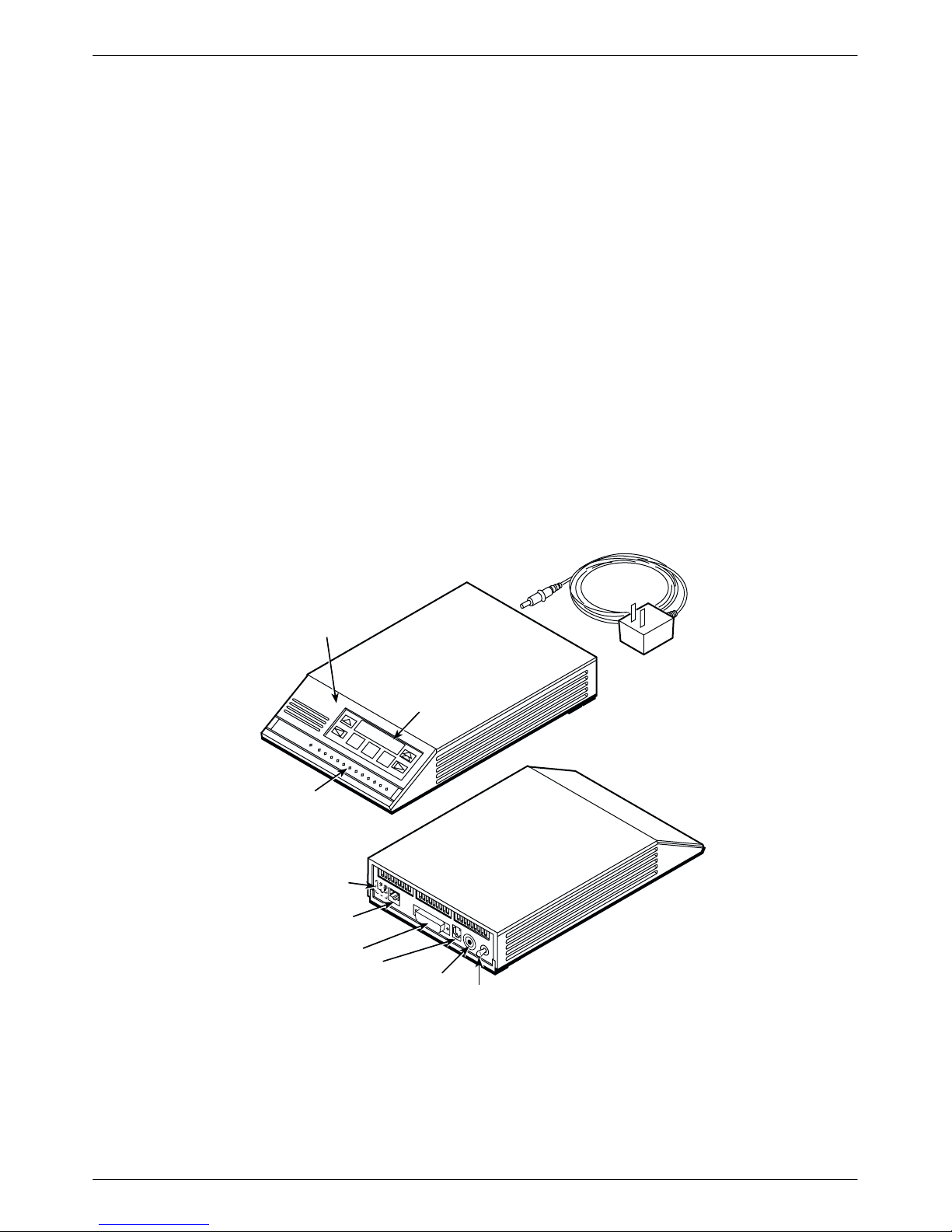
Model 3920Plus Standalone Singleport Modems
The Model 3920Plus singleport (Figures 1-1 and 1-2) is a standalone modem capable of either
4-wire/2-wire leased-line or dial operation. This modem is controlled using either AT commands
or the DCP. The DCP consists of a liquid crystal display (LCD), three function keys, four
directional keys, and a row of 13 LED status indicators. For a better understanding of DCP
operation, refer to Chapter 3, DCP Operation.
DIAGNOSTIC
CONTROL
PANEL
STATUS
INDICATORS
LEASED
DIAL
DTE 1
NMS
LCD AND
KEYPAD
POWER IN
POWER
ON/OFF
POWER
SUPPLY
97-14678-02
1-2 October 1998 3920-A2-GH30-40
Figure 1-1. 3920-A2 Standalone Modem
Page 15
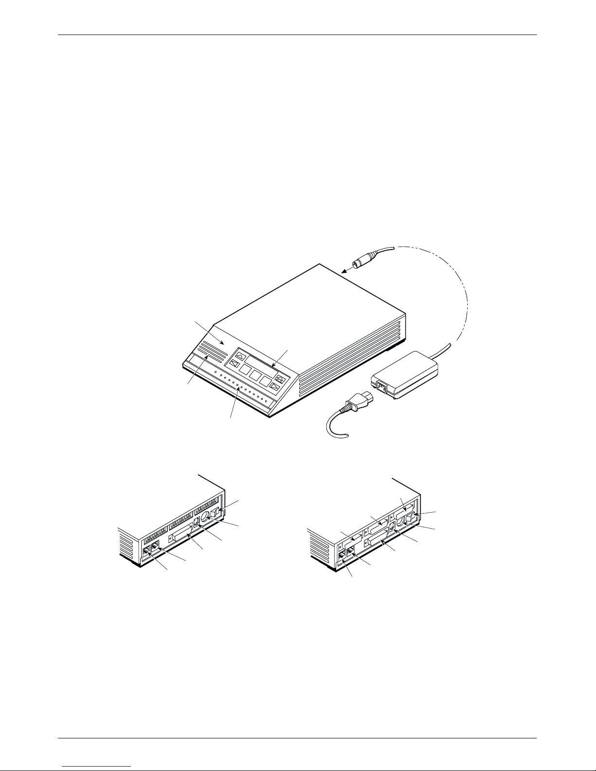
Model 3920Plus Standalone Multiport Modem
The Model 3920Plus multiport is a standalone modem (Figure 1-2), with an integral time division
multiplexer (TDM) and a modem sharing device (MSD) as standard equipment. The TDM
provides time division multiplexing of up to four independent ports over point-to-point lines using
the V.34 family or V.32 family modulation. The MSD allows multiple physical ports on a tributary
modem to share a single communication channel using the V.34 family, V.32 family, or TMp
modulation. The TDM/MSD multiplexer (commonly referred to as “mux”) can be enabled or
disabled to allow a greater degree of application flexibility.
The 3920Plus multiport modem also operates over a 4-wire/2-wire leased or dial network and is
controlled using the same DCP employed on the Model 3920Plus singleport standalone modem.
Model 3920Plus Singleport and
Multiport Housing
DIAGNOSTIC
CONTROL
PANEL
Chapter Title
SPEAKER
Singleport Modem
Back Panel
DIAL
LEASED
STATUS
INDICATORS
NMS
DTE 1
POWER
ON/OFF
POWER IN
LCD AND
KEYPAD
POWER
CORD
Multiport Modem
Back Panel
DTE 4
DTE 3
DTE 2
DIAL
LEASED
POWER
SUPPLY
POWER
ON/OFF
POWER IN
NMS
DTE 1
496-14684-01
Figure 1-2. 3920-A1 Standalone Singleport and Multiport Modems
1-33920-A2-GH30-40 October 1998
Page 16
COMSPHERE 392xPlus Modems
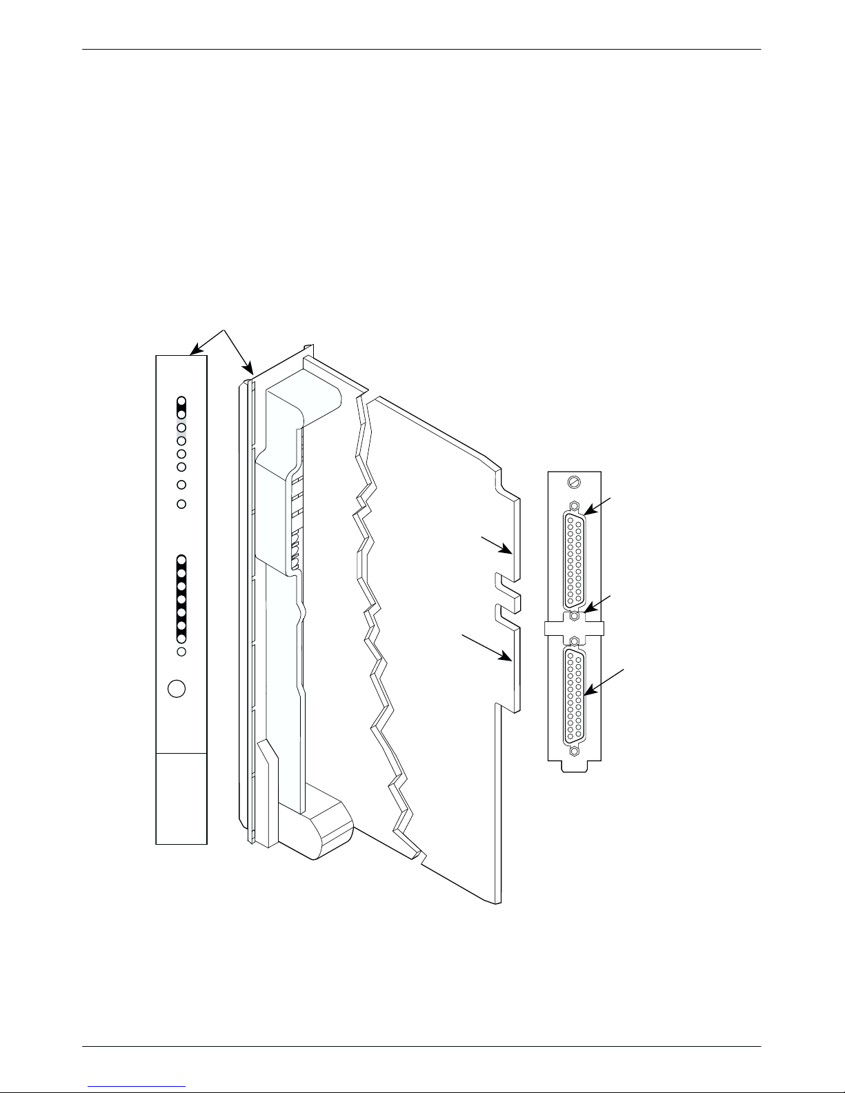
Model 3921Plus Singleport Carrier-Mounted Modem
The Model 3921Plus singleport is a carrier-mounted modem (Figure 1-3) capable of either
4-wire/2-wire leased-line or dial operation. The modem installs into a COMSPHERE 3000 Series
Carrier, occupying a single slot. The modem’s faceplate has sixteen (16) LED status indicators for
displaying modem activity and an audio speaker jack for the carrier’s optional speaker .
The modem’s back panel has two edge card connectors that mount into a connector plate. This
connector plate has two DB-25-S connectors, one providing an EIA-232-D DTE interface and one
for future functionality.
FACEPLATE
Status
Pwr
Alrm
142
Test
Dial
125
RI
Busy
Serv
SQ
EIA232/V.24
EDGE CARD
CONNECTOR
103
TXD
104
RXD
105
RTS
106
CTS
107
108
109
DSR
DTR
LSD
FUTURE
USE
BACK
CONNECTOR
PLATE
EIA232/V.24
EIA232/V.24
CONNECTOR
GROUNDING
TAB
Front Panel
(3800)
Spkr
RS366A/V.25
(3600/3500)
V.35
FUTURE
USE
3921Plus
496-14178a-04
Figure 1-3. Model 3921Plus Singleport Modem
1-4 October 1998 3920-A2-GH30-40
Page 17
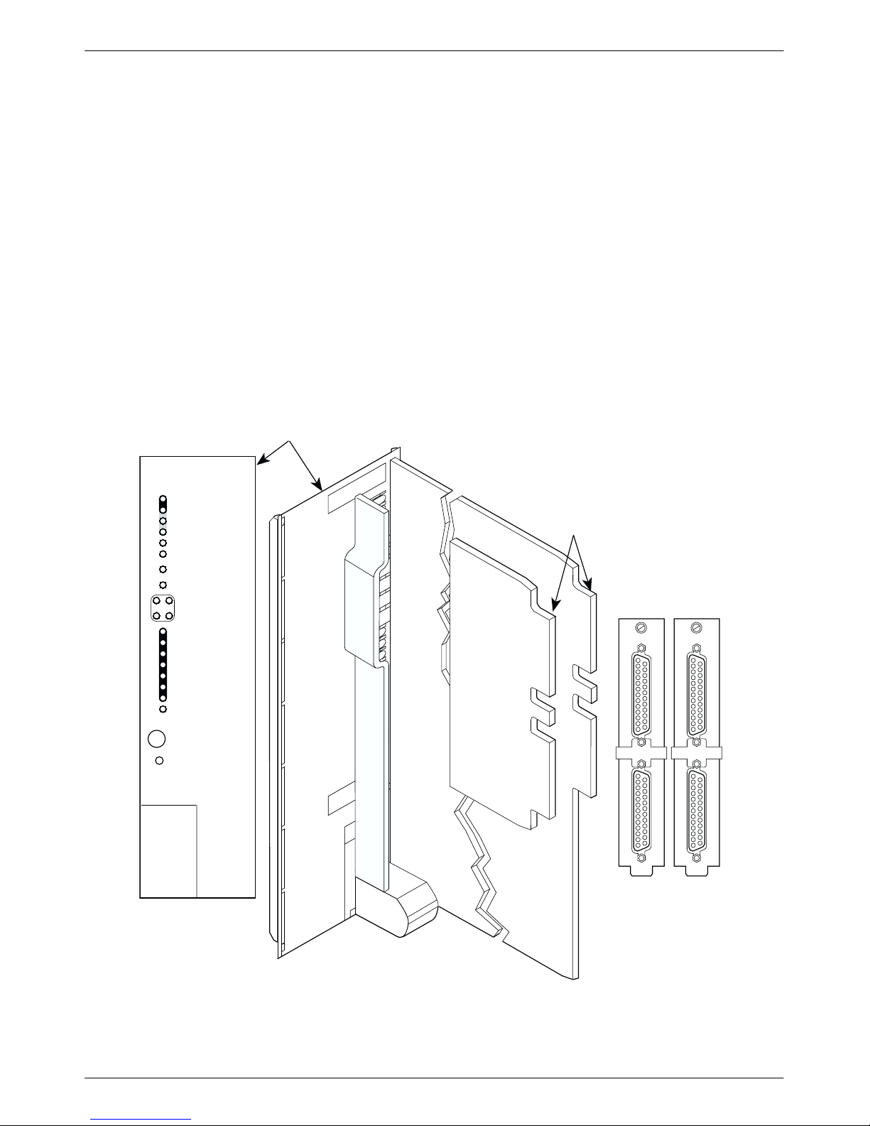
Model 3921Plus Multiport Carrier-Mounted Modem
The Model 3921Plus multiport is a carrier-mounted modem (Figure 1-4) equipped with an integral
time division multiplexer (TDM) with a modem sharing device (MSD). The modem installs into
the COMSPHERE 3000 Series Carrier, occupying two slots. The modem’s faceplate covers two
slots in the carrier. It has twenty (20) LED status indicators for displaying modem activity and an
audio speaker jack for the carrier’s optional speaker .
The modem’s back panel has four edge card connectors that mount into two connector plates. Each
connector plate has two DB-25-S connectors providing four EIA-232-DTE interfaces.
Both the singleport and multiport Model 3921Plus modems derive ac power from the
COMSPHERE 3000 Series Carrier’s backplane, which is a common bus to all devices installed in
the carrier. The user interface to any Model 3921Plus modem is through the shared diagnostic
control panel (SDCP), an optional feature which operates in a manner similar to the DCP on the
Model 3920Plus modems. For a better understanding of DCP operation, refer to Chapter 3,
DCP Operation.
FACEPLATE
Introduction
Status
Pwr
Alrm
Test
142
Dial
RI
125
Busy
Serv
SQ
13
Port
24
TXD
103
RXD
104
RTS
105
CTS
106
DSR
107
DTR
108
LSD
109
Front Panel
Spkr
3921Plus
EDGE CARD
CONNECTORS
PORT
PORT
3
PORT
4
1
PORT
2
BACK
CONNECTOR
PLATES
DTE B DTE A
DTE B DTE A
Figure 1-4. Model 3921Plus Multiport Modem
49614423a-03
1-53920-A2-GH30-40 October 1998
Page 18

COMSPHERE 392xPlus Modems
392xPlus Operational Modes
The 392xPlus operational modes determine how your modem performs in various applications.
These operational modes are determined by your modem model and the selected configuration
options.
There are two operational modes:
• Singleport. Operates on both the singleport and multiport modem models. The Singleport
mode only supports one port (DTE 1). Singleport mode is the only operational mode for the
singleport modem models. For the multiport modem models, Singleport mode is in effect
when the MUX Mode configuration option is set to Disable.
• Multiport. Operates only on the multiport modem models. Multiport mode is in effect when
the MUX Mode configuration option is set to TDM/MSD or DTE_Bridge. It supports from
one to four ports (DTE 1–4), depending on how the modem is configured.
Using T able 1-1, identify your modem’s operational mode based on the 392xPlus modem model
and its selected MUX mode configuration option.
Table 1-1
392xPlus Operational Modes
392xPlus Modem
Singleport n/a Singleport
Multiport MUX Mode: Disabled
MUX Mode Configuration Option Operational Mode
Singleport
MUX Mode set to:TDM/MSD, DTE_Bridge
Multiport
Use the identified operational mode (Singleport or Multiport) to choose the configuration options
that are appropriate for your modem’s application. Refer to Chapter 5, Configure Branch, for
information on configuration options.
1-6 October 1998 3920-A2-GH30-40
Page 19

392xPlus Modem Features
The 392xPlus modems share a wide variety of features.
• Asynchronous DTE rates of 115.2 kbps and 76.8 kbps.
• Asynchronous data compression and error correction.
• Synchronous data compression.
• Additional VF parameters under the V.32 and V.34 family modulations in 4-wire mode.
• International Support to correctly detect the call progress signals (dial tone, busy, fast busy,
ringback) for a variety of countries.
• Channel adaptive Trellis-Coded Modulation– Paradyne’s advanced Trellis-Coded
transparent forward error correction for Trellis multipoint and high-speed point-to-point
applications.
• Convenient migration to new or optional features through software downloading.
• Extended data circuits with diagnostic capabilities.
• Network management system (NMS) support through the COMSPHERE 6800 or
6700 Series NMS using Advanced Diagnostic protocol (ADp).
Introduction
• Automatic and manual backup with standby capabilities for 4-wire/2-wire leased-line
applications. (The backup facility may be either a 2-wire dial line or a 2-wire leased line.)
392xPlus Singleport Modem Features
Features specific to 392xPlus singleport modems are:
• Four-wire/two-wire leased-line modulations.
• Dial-line modulations.
Refer to Table 1-2 in the Technical Specifications section of this chapter for leased- and dial-line
modulations information.
392xPlus Multiport Modem Features
Features specific to 392xPlus multiport modems are:
• Four-port time division multiplexer (TDM) operation.
• Modem Sharing Device (MSD).
• Digital Bridging.
• Mux enabled, four-wire/two-wire leased-line modulations: V.34 (33,600, 28,800, 24,000,
19,200, 16,800, 14,400, 12,000, 9600, 7200, 4800, and 2400 bps), V.32terbo (19,200 and
16,800 bps), V.32bis (14,400, 12,000, 9600, 7200, and 4800 bps), V.32 (9600 and 4800 bps),
and Trellis Multipoint (TMp) (19,200, 14,400, 9600, 7200, 4800, and
2400 bps).
• Mux enabled, dial-line modulations: V.34 (33,600, 28,800, 24,000, 19,200, 16,800, 14,400,
12,000, 9600, 7200, 4800, and 2400 bps), V.32terbo (19,200 and 16,800 bps), V.32bis
(14,400, 12,000, 9600, 7200, and 4800 bps), V.32 (9600 and 4800 bps).
1-73920-A2-GH30-40 October 1998
Page 20

COMSPHERE 392xPlus Modems
Applications
Multipoint
Multipoint is available in all 392xPlus modem models. It utilizes leased-line circuits for time
sharing the same front-end processor (FEP) port with multiple remote locations. The FEP (via the
control modem) regulates traffic on the line by continuously polling the tributary DTE(s) in a
predefined sequence. Only one tributary can communicate with the control modem at a given time.
Modems configured for Trellis Multipoint (TMp) cannot be used in a point-to-point, constant
carrier application. (Refer to the Leased Line — Multiport Mode or the Leased Line — Singleport
Mode section in Chapter 5, Configure Branch, for configuration options.)
Dual-Leased Backup
Dual-Leased Backup is available in all 392xPlus modems. It enables a 2-wire leased line to be
used as the backup facility instead of the normal 2-wire dial line. Plug the leased line into the jack
labeled DIAL on the back panel of the modem (see Figure 2-2 in Chapter 2, Modem Installation),
and enable the Dual_Leased_Ln configuration option. (Refer to the Leased Line — Multiport
Mode or the Leased Line — Singleport Mode section in Chapter 5, Configure Branch, for
configuration options.) Except for dialing, ring indication, and call progression functions, you
control the backup function as if it were a normal dial backup.
MSD
Digital Bridging
The Modem Sharing Device (MSD) is only available in 392xPlus multiport modems. It allows
from 2 to 4 physical ports to share a communication channel. When the MUX Mode option is set
to TDM/MSD on a tributary, and at least one port has the MSD mode setting enabled, then MSD is
enabled. For more information, refer to the Multiport Mode section of Chapter 5, Configure
Branch, for configuration options or the Point-to-Point MSD and Multipoint MSD sample
configurations in Appendix G, Sample Configurations.
When MSD mode is enabled:
• The MSD Control configuration option is added at the end of the Mux Sub-Group.
• The EIA Port Sub-group includes the RTS Antistream configuration option.
The Digital (DTE) Bridging application is only available in 392xPlus multiport modems. It
provides the ability for dial backup of a multipoint configuration by bridging the signal on the
digital side of the FEP-end modems. In this configuration, only two ports (both on the FEP side)
are used on the control and backup modems. Data received on Port 1 is transmitted across the
communication link, as well as looped back out of Port 2. Data received across the communication
link and on Port 2 is sent out of Port 1. For more information, refer to the Multiport Mode section
of Chapter 5, Configure Branch, for information on the configuration option (DTE Bridge), or
Appendix G, Sample Configurations, for the Digital Bridging sample configuration.
1-8 October 1998 3920-A2-GH30-40
Page 21

V.34 Modulation
Introduction
When the Digital Bridging feature is enabled, a new menu is present with the following conditions:
• TDM capability is disabled when DTE Bridge configuration option is set to Enable,
therefore the rate of Port 1 is forced to run at the line rate.
• Configuration options are provided for Port 1 only; Port 2 cannot be configured.
• Ports 3 and 4 are not available.
• Port-related tests, such as digital loopbacks and Pattern tests, are available for Port 1.
• DTE Status, Health and Status, and LED control are available for both Ports 1 and 2.
The V.34 modulation capability is available in all 392xPlus modems. In Singleport mode the V .34
modulation is compatible with other vendors’ modems that support the ITU-T V.34 modulation. In
Multiport mode, the V.34 modulation will not operate at line rates of 31,200, 26,400, and 21,600
bps.
The ITU-T standard for V.34 modulation includes dial- or leased-line operation. For proper
leased-line operation, one modem must be designated as the answer modem while the other
modem must be designated as the originate modem.
The V.34 standard also includes asymmetric rates, automatic adjustment of the transmit power
level, and automatic adjustment of the symbol (baud) rate for optimal data throughput. These
automatic adjustments are made during the training, or modem synchronization, phase via special
line-probing techniques that establish the top-most viable rate of operation. Due to these
techniques, true fixed-rate operation of the modems using V.34 modulation is not possible, since
the line condition may not be capable of supporting the selected rate. Thus, using CT111 and
CT112 for rate control of extended data circuits cannot be used.
When operating in V.34 modulation, you can use the top line of the Quick Configuration screen to
view the current modem transmit rate, the symbol or baud rate, and the transmit level. The
392xPlus modems offer separate options for leased and dial lines to override the asymmetric rate
function, since this can cause problems for certain DTE equipment, Also, each symbol rate
supports a subset of data rates, which make up the whole of the V.34 standard.
Symbol Rate
3429 4800 – 33.6K
3200 4800 – 31.2K
3000 4800 – 28.8K
2800 4800 – 31.2K
2743 4800 – 31.2K
2400 2400 – 24.0K
Supported Data Rates
When using the V.34 modulation on leased lines with a 2-wire leased backup facility, the backup
line check feature, which tests the backup leased lines for connectivity, cannot be used.
1-93920-A2-GH30-40 October 1998
Page 22

COMSPHERE 392xPlus Modems
Multiport Backup
When the 392xPlus multiport modem has the MUX Mode configuration option set to either
TDM/MSD or DTE Bridge, it is in Multiport mode, and either dial lines or a 2-wire leased line can
be used to back up the primary 4-wire leased line. Backup can be performed automatically upon
loss of the primary leased line, and automatic dial standby also can be used to automatically return
the modems to the primary leased line when restored.
When you use backup functions while in Multiport mode, the modem’s automode feature is forced
to Disable. This ensures that the mux is not accidentally disabled by answering a call, which is
using modulation where Multiport mode is not supported. It is important that both modems
participating in the backup are in Multiport mode with the same dial-line modulation.
NOTE
When a 2400 V.34 modulation connection occurs on one end of a
modem pair with configuration options set for Asymmetric rates, the
other modem is 24K due to the 2400 symbol rate it uses.
Synchronous Data Compression
The 392xPlus standalone and carrier-mounted modems are available with Synchronous Data
Compression (SDC). Refer to Appendix H, Synchronous Data Compression, for more information.
Government Requirements and Equipment Return
Certain governments require that instructions pertaining to modem connection to the public
switched telephone network be included in the installation and operation manual. Specific
instructions are listed in the following sections.
United States
NOTICE TO USERS OF THE PUBLIC SWITCHED TELEPHONE NETWORK
1. This equipment complies with Part 68 of the FCC rules. On the equipment is a label that
contains, among other information, the FCC registration number and ringer equivalence
number (REN) for this equipment. The label is located on the bottom of the
Model 3920Plus modem and on the modem’s circuit card assembly on the
Model 3921Plus. If requested, this information must be provided to the telephone
company.
2. Page A of this manual contains the Universal Service Order Codes (USOC) associated with
the services on which the equipment is to be connected.
3. An FCC compliant telephone cord and modular plug is provided with this equipment. This
equipment is designed to be connected to the telephone network or premises wiring using a
compatible modular jack which is Part 68 compliant. See Installation Instructions for
details.
1-10 October 1998 3920-A2-GH30-40
Page 23

Introduction
4. The ringer equivalence (REN) is used to determine the quantity of devices which may be
connected to the telephone line. Excessive RENs on the telephone line may result in the
devices not ringing in response to an incoming call. In most, but not all areas, the sum of
the RENs should not exceed five (5.0). T o be certain of the number of devices that may be
connected to the line, as determined by the total RENs, contact the telephone company to
determine the maximum RENs for the calling area.
5. If the 392xPlus modem causes harm to the telephone network, the telephone company will
notify you in advance that temporary discontinuance of service may be required. But if
advance notice is not practical, the telephone company will notify the customer as soon as
possible. Also, you will be advised of your right to file a complaint with the FCC if you
believe it is necessary.
6. The telephone company may make changes in its facilities, equipment, operations, or
procedures that could affect the operation of the equipment. If this happens, the telephone
company will provide advance notice for you to make the necessary modifications in order
to maintain uninterrupted service.
7. The user is not authorized to repair or modify the equipment.
8. This equipment cannot be used on public coin service provided by the telephone company.
Connection to Party Line Service is subject to state tariffs. (Contact the state public utility
commission, public service commission or corporation commission for information.)
9. If you experience trouble with this equipment, please contact your sales or service
representative (as appropriate) for repair or warranty information. If the product needs to
be returned to the company service center for repair, contact them directly for return
instructions using one of the following methods:
• Via the Internet: Visit the Paradyne World Wide Web site at http://www.paradyne.com
• Via Telephone: Call our automated call system to receive current information via fax or
to speak with a company representative.
— Within the U.S.A., call 1-800-870-2221
— Outside of U.S.A., call 1-727-530-2340
If the trouble is causing harm to the telephone network, the telephone company may
request that you remove the equipment from the network until the problem is resolved.
1-113920-A2-GH30-40 October 1998
Page 24

COMSPHERE 392xPlus Modems
Canada
NOTICE TO USERS OF THE CANADIAN PUBLIC SWITCHED TELEPHONE NETWORK
The Canadian Department of Communications label identifies certified equipment. This
certification means that the equipment meets certain telecommunications network protective,
operational, and safety requirements. The Department does not guarantee the equipment will
operate to the user’s satisfaction.
Before installing this equipment, the user should ensure that it is permissible to be connected to the
facilities of the local telecommunications company. The equipment must also be installed using an
acceptable method of connection. In some cases, the company’s inside wiring associated with a
single line individual service may be extended by means of a certified connector assembly
(telephone extension cord). The customer should be aware that compliance with the above
conditions may not prevent degradation of service in some situations.
Repairs to certified equipment should be made by an authorized Canadian maintenance facility
designated by the supplier. Any repairs or alterations made by the user to this equipment, or
equipment malfunctions, may give the telecommunications company cause to request the user to
disconnect the equipment.
Users should ensure for their own protection, that the electrical ground connections of the power
utility, telephone line and internal metallic water pipe system, if present, are connected together.
This precaution may be particularly important in rural areas.
CAUTION
Users should not attempt to make such connections
themselves, but should contact the appropriate electric
inspection authority, or electrician, as appropriate.
The Load Number (LN) is labeled on the equipment. The Load Number assigned to each terminal
device denotes the percentage of the total load to be connected to a telephone loop which is used
by the device to prevent overloading. The termination on a loop may consist of any combination of
devices subject only to the requirement that the total of the Load Numbers of all devices does not
exceed 100.
If your equipment is in need of repair, refer to the procedure in the Government Requirements
and Equipment Return section earlier in this chapter.
1-12 October 1998 3920-A2-GH30-40
Page 25

Technical Specifications
T able 1-2 shows the technical specifications for the 392xPlus modems.
Technical Specifications for 392xPlus Modems
Introduction
Table 1-2
(1 of 2)
Specifications
APPROVALS
Model 3920Plus, 3921Plus, and
COMSPHERE 3000 Series Carrier
ENVIRONMENT
Operating Temperature
Relative Humidity 5% to 90% (noncondensing)
Shock and Vibration Withstands normal shipping
Storage Temperature
DTE INTERFACE
25-pin D-subminiature connector EIA-232-D/ITU–T V.24
MODEL 3920Plus POWER SUPPLY
AC POWER REQUIREMENTS
POWER CONSUMPTION
Model 3920Plus Singleport (3920-A1-xxx) 6 watts (typical, including power supply , speaker off)
Model 3920Plus Singleport (3920-A2-xxx) 8 watts (typical, including power supply , speaker off)
Model 3921Plus Singleport 4 watts (typical, each card) (Speaker consumption is approximately
Model 3920Plus Multiport 8 watts (typical, including power supply, speaker off)
Model 3921Plus Multiport 6 watts (typical, each card) (Speaker consumption is approximately
DIMENSIONS
Weight 2.5 pounds (1.14 kg) Model 3920Plus (without power supply)
Height 2.1 inches (5.4 cm) Model 3920Plus
Width Singleport
Depth 12.1 inches (30.8 cm) Model 3920Plus
TELEPHONE INTERFACE
Leased-Line Connectivity JM8 (Model 3920Plus )
Dial-Line Connectivity RJ11C Permissive
Refer to the product labeling or contact your service representative.
32°F (0°C) to 122°F (50°C)
–4°F (–20°C) to 158°F (70°C)
100 to 250 V ac, 50 to 60 Hz
1 watt at high volume.)
1 watt at high volume.)
1.0 pounds (0.45 kg) Model 3921Plus
7.1 inches (18.1 cm) Model 3921Plus
7.6 inches (19.4 cm) Model 3920Plus
0.9 inches (2.3 cm) Model 3921Plus
Multiport
7.6 inches (19.4 cm) Model 3920Plus
1.8 inches (4.6 cm) Model 3921Plus
13.4 inches (34.0 cm) Model 3921Plus
50-pin mass termination (Model 3921Plus )
RJ21X Permissive 50-pin connector (Model 3921Plus )
Description
1-133920-A2-GH30-40 October 1998
Page 26

COMSPHERE 392xPlus Modems
Table 1-2
(2 of 2)
Technical Specifications for 392xPlus Modems
Specifications Description
TRANSMIT LEVEL
Leased Line (North America) 0 through –15 dBm (in 1 dBm decrements)
Factory default is 0 dBm
Leased Line (All Other Countries) –1 through –15 dBm (in 1 dBm decrements)
Factory default is country dependent
Dial Line (North America) –10 through –32 dBm (in 1 dBm decrements)
Factory default is Permissive (–9 dBm)
Dial Line (All Other Countries) Level setting is not accessible to the user
Factory default is country dependent
COMPATIBILITY Leased-Line Modulations:
ITU-T V .34 (33,600, 31,200, 28,800, 26,400, 24,000, 21,600, 19,200,
16,800, 14,400, 12,000, 9600, 7200, 4800, 2400 bps)
Paradyne V.32terbo (19,200, 16,800 bps)
ITU-T V.32bis (14,400, 12,000, 9600, 7200, 4800 bps)
ITU-T V.32 (9600, 4800 bps)
Paradyne Trellis Multipoint (19,200, 14,400, 9600, 7200, 4800,
2400 bps)
ITU-T V.22bis (2400 bps)
ITU-T V.27bis (4800, 2400 bps)
ITU-T V.33 (14,400, 12,000 bps)
ITU-T V.29 (9600, 7200, 4800 bps)
Paradyne Point-to-Point Diagnostic (2400 bps)
Dial-Line Modulations:
ITU-T V .34 (33,600, 31,200, 28,800, 26,400, 24,000, 21,600, 19,200,
16,800, 14,400, 12,000, 9600, 7200, 4800, 2400 bps)
Paradyne V.32terbo (19,200, 16,800 bps)
ITU-T V.32bis (14,400, 12,000, 9600, 7200, 4800 bps)
ITU-T V.32 (9600, 4800 bps)
ITU-T V.22bis (2400 bps)
ITU-T V.22 (1200 bps)
ITU-T V.23 (1200, 600 bps)
ITU-T V.21 (300 bps)
Bell 212A (1200 bps)
Bell 103J (300 bps)
Paradyne Point-to-Point Diagnostic (2400 bps)
ERROR CONTROL ITU-T V.42
MNP 4–2
DATA COMPRESSION ITU-T V.42bis
MNP Class 5
V.42t, Paradyne Proprietary Synchronous Data Compression
1-14 October 1998 3920-A2-GH30-40
Page 27

Overview
Modem Installation
Overview 2-1. . . . . . . . . . . . . . . . . . . . . . . . . . . . . . . . . . . . . . . . . . . . . . . . . . . .
392xPlus Modem Package 2-1. . . . . . . . . . . . . . . . . . . . . . . . . . . . . . . . . . . . . . .
Customer-Supplied Equipment 2-2. . . . . . . . . . . . . . . . . . . . . . . . . . . . . . . . .
Model 3920Plus Modem Installation 2-3. . . . . . . . . . . . . . . . . . . . . . . . . . . . . . .
Connecting Cables to the Model 3920Plus Modem 2-3. . . . . . . . . . . . . . . . . . . .
Data Terminal Equipment Connection 2-6. . . . . . . . . . . . . . . . . . . . . . . . . . .
Power Supply Connection (3920-A1-xxx) 2-6. . . . . . . . . . . . . . . . . . . . . . . .
Power Supply Connection (3920-A2-xxx) 2-6. . . . . . . . . . . . . . . . . . . . . . . .
Leased-Line Network Connection 2-7. . . . . . . . . . . . . . . . . . . . . . . . . . . . . . .
Dial Network Connection 2-7. . . . . . . . . . . . . . . . . . . . . . . . . . . . . . . . . . . . .
Leased Backup Connection 2-7. . . . . . . . . . . . . . . . . . . . . . . . . . . . . . . . . . . .
Dial Backup Connection 2-7. . . . . . . . . . . . . . . . . . . . . . . . . . . . . . . . . . . . . .
Network Management System Connection 2-7. . . . . . . . . . . . . . . . . . . . . . . .
Removing and Replacing the Model 3920Plus Modem 2-8. . . . . . . . . . . . . . . . .
Model 3921Plus Modem Installation 2-8. . . . . . . . . . . . . . . . . . . . . . . . . . . . . . .
Removing the Model 3921Plus Modem 2-13. . . . . . . . . . . . . . . . . . . . . . . . . . . . .
392xPlus Modem Power-Up 2-13. . . . . . . . . . . . . . . . . . . . . . . . . . . . . . . . . . . . .
Selecting Factory Configuration Options 2-13. . . . . . . . . . . . . . . . . . . . . . . . . . . .
Using the Diagnostic Control Panel (DCP) 2-14. . . . . . . . . . . . . . . . . . . . . . . .
This chapter provides a list of equipment supplied with 392xPlus modems, as well as a list of
customer supplied equipment. In addition, it describes how to install and remove the 392xPlus
modems, and how to select a factory preset configuration using the DCP.
2
392xPlus Modem Package
After opening the modem’s package, check for damage and verify that the following items are
present:
For the standalone models
• Installation instructions
• Model 3920Plus modem
• Power supply with power cord (3920-A1-xxx) or power transformer (3920-A2-xxx)
• One 6-position, 4-wire modular cord (in selected models)
• One 8-position, 8-wire modular cord (in selected models)
2-13920-A2-GH30-41 February 2002
Page 28

COMSPHERE 392xPlus Modems
For the carrier-mounted models
• Installation instructions
• Model 3921Plus modem
• One (singleport) connector plate or two (multiport) connector plates with two DB-25-S edge
card connectors on each plate
If any hardware components are damaged, notify your service representative. Return equipment
using the procedures described in the Government Requirements and Equipment Return section of
Chapter 1, Introduction.
Customer-Supplied Equipment
The following customer-supplied equipment is required to complete a data communications system
using the Model 3920Plus modem:
• One (singleport) or four (multiport) DTEs with available EIA-232-D serial port(s).
• Standard EIA-232-D cables with one (singleport) or four (multiport) DB-25-P connectors at
one end to attach to the modem.
• One or more of the following modular leased or dial network interfaces:
— JM8 for leased-line configurations.
— RJ11C for dial permissive configurations.
— One 8-position, 8-wire modular cord (for leased backup purposes).
The following customer-supplied equipment is required for the installation of a Model 3921Plus
modem:
• A COMSPHERE 3000 Series Carrier.
• A 50-pin mass termination cable.
• One or more of the following modular or 50-pin leased or dial network interfaces:
— RJ11C for single-line dial permissive configurations.
— RJ21X for multiple-line dial permissive configurations.
— 66 punchdown block.
• One Network Interface Module (NIM) for modems installed in Slots 1–8 and one NIM for
modems installed in Slots 9–16 (required for dial-line configurations).
For installation of the COMSPHERE 3000 Series Carrier into a cabinet, refer to the COMSPHERE
3000 Series Carrier, Installation Manual.
2-2 October 1998 3920-A2-GH30-40
Page 29

Model 3920Plus Modem Installation
Before installing your standalone modem, make sure your installation site is clean and
well-ventilated. Allow space around the modem for installing cables and telephone cords, and
make sure the modem is located within reach of the ac power outlet. The distance between your
modem and DTE should be minimized if DTE data rates exceed 19,200 bps. Also, low capacitance
cables may be necessary for speeds greater than 19,200 bps or distances greater than 50 feet.
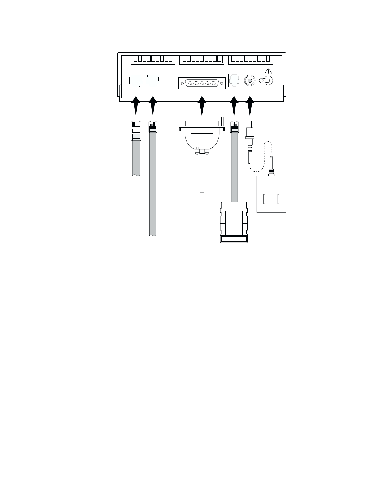
The back panel of the Model 3920Plus modem (Figure 2-1) has the following switches and
connectors:
• An ON/OFF power switch.
• An 8-pin DIN type power receptacle (PWR) for the dc power supply.
• An 8-pin modular keyed jack (LEASED) for 4-wire/2-wire leased lines.
• An 8-pin modular keyed jack (DIAL) for backup lines (2-wire dial or 2-wire leased).
• A 4-pin modular jack (NMS) for the Network Management System connection.
• One (singleport) or four (multiport) 25-pin DB-25-S receptacles for the DTE interfaces.
Modem Installation
Connecting Cables to the Model 3920Plus Modem
Instructions for connecting cables to the TELCO jack types using the appropriate cables apply to
both singleport and multiport Model 3920Plus modems. Figure 2-1 illustrates the Model 3920Plus
singleport (Model No. 3920-A2-xxx) modem. Figure 2-2 illustrates the Model 3920Plus multiport
modem. For pin assignments, refer to Appendix C, Pin Assignments.
2-33920-A2-GH30-40 October 1998
Page 30
COMSPHERE 392xPlus Modems
DIAL
LEASED
DTE 1
NMS
PWR ON
OFF
LEASED-LINE
NETWORK
8-POSITION
PLUG
DATA
TERMINAL
EQUIPMENT
DB-25-P
CONNECTOR
SUB-MINIATURE
DIAL NETWORK
6-POSITION PLUG
4-POSITION
PLUG FOR
NETWORK
HUBBING
MANAGEMENT
DEVICE
POWER
SUPPLY
SYSTEM
OPERATION
98-14677-03
Figure 2-1. Model 3920Plus Singleport (3920-A2-xxx) Back Panel and Power Supply
2-4 October 1998 3920-A2-GH30-40
Page 31

DB-25-S CONNECTORS
Modem Installation
LEASED-LINE
NETWORK
8-POSITION,
8-CONDUCTOR
PLUG
NETWORK
6-POSITION,
4-CONDUCTOR
LEASED BACKUP
8-POSITION,
8-CONDUCTOR
DTE 2 DTE 3 DTE 4
DTE 1LEASED DIAL NMS PWR ON OFF
DATA
TERMINAL
EQUIPMENT
DB-25-P
CONNECTOR
DIAL
NETWORK
MANAGEMENT
SYSTEM
PLUG
OR
SUB-MINIATURE,
4-POSITION,
4-CONDUCTOR
PLUG
PLUG
HUBBING
DEVICE
!
POWER
SUPPLY
POWER
CORD
495-14788
Figure 2-2. Model 3920Plus Multiport Back Panel and Power Supply
2-53920-A2-GH30-40 October 1998
Page 32

COMSPHERE 392xPlus Modems
Data Terminal Equipment Connection
Use the following steps to connect an EIA-232-D cable from the modem to a DTE:
1. Make sure the modem is powered OFF.
2. Connect the DB-25-P (plug) connector on the cable to the first or only DB-25-S (socket)
connector (Figure 2-1 or 2-2) on the modem’s back panel, labeled DTE 1. Use a small
screwdriver to secure the cable to the modem.
3. For multiport modems, connect cables similarly to DTE 2 through DTE 4.
4. For each port, connect the DB-25-P connector on the other end of the cable to the DB-25-S
connector on the DTE. Use a small screwdriver to secure the cable to the DTE.
DTE rates above 19.2 bps require cable lengths less than fifty feet as specified by
the RS323 standard.
NOTE
Power Supply Connection (3920-A1-xxx)
Use the following steps to connect the modem to an ac power outlet:
1. Make sure the modem is powered OFF.
2. Insert the power supply’s 8-pin DIN connector into the modem’s back panel dc power
receptacle, labeled PWR (Figure 2-2).
3. Connect the power cord to the power supply.
4. Connect the power cord to a grounded ac power outlet.
Power Supply Connection (3920-A2-xxx)
Use the following steps to connect the modem to an ac power outlet:
1. Make sure the modem is powered OFF.
2. Insert the power supply’s cylindrical connector into the modem’s back panel dc power
receptacle, labeled PWR (Figure 2-1).
3. Connect the power module to an ac power outlet.
2-6 October 1998 3920-A2-GH30-40
Page 33

Leased-Line Network Connection
Use the following steps to connect the leased-line network interface:
1. Insert the 8-position, 8-conductor modular plug into the jack labeled LEASED
(Figure 2-1 or 2-2).
2. Insert the other end of the modular cord into the leased-line network interface.
3. If the Model 3920Plus has a backup line, follow the steps listed in the Dial Backup
Connection section.
Dial Network Connection
The telephone company provides the line termination jacks for the permissive service you request.
Advance coordination with the telephone company is suggested when connecting the modem to
telephone dial lines (PSTN).
In the Permissive mode, the modem’s transmit output level is fixed at –9 dBm. The telephone
company assumes that the line loss is 3 dB and no compensation is provided for additional losses.
A Permissive mode telephone line is usually terminated with a USOC RJ11C jack.
Modem Installation
Leased Backup Connection
Use the following steps to connect the modem to the 2-wire leased backup network interface:
1. Insert the 8-position, 8-conductor modular plug into the jack labeled DIAL
(Figure 2-1 or 2-2).
2. Insert the other end of the modular cord into the leased-line network interface.
Dial Backup Connection
Use the following steps to connect the modem to the dial network interface:
1. Insert the 6-position, 4-conductor modular plug into the jack labeled DIAL
(Figure 2-1 or 2-2).
2. Insert the other end of the modular cord into the dial network interface.
Network Management System Connection
Use the following steps to connect the modem to the network management system (NMS):
1. Insert the sub-miniature, 4-conductor modular plug of the 3600 Hubbing Device into the
jack labeled NMS (Figure 2-1 or 2-2). Refer to the 3600 Hubbing Device, Feature Number
3600-F3-300, Installation Instructions for a description of the 3600 Hubbing Device.
Installation for the 3920Plus is the same as for the 3610 DSU.
2. Connect the 3600 Hubbing Device to the NMS (Figure G-5 in Appendix G).
2-73920-A2-GH30-40 October 1998
Page 34

COMSPHERE 392xPlus Modems
Removing and Replacing the Model 3920Plus Modem
T o remove and replace the Model 3920Plus modem, perform the following steps:
1. Make sure the modem is offline. Press the modem’s back panel power switch to OFF.
2. Disconnect the power cord from the ac power outlet.
3. Disconnect the dc power cable from the connector on the back of the modem.
4. Disconnect the leased-line and dial modular cord(s) from the modem’s back panel.
5. Disconnect the DTE interface cable(s) from the modem’s back panel.
If the modem is to be removed for service, return it to the company using the procedures
described in Government Requirements and Equipment Return in Chapter 1, Introduction.
6. Install the replacement modem as described in the Model 3920Plus Modem Installation
section of this chapter, and configure it the same way as the modem being replaced.
Model 3921Plus Modem Installation
When removing the Model 3921Plus from the carrier, always
use a ground strap when handling the modem. Always store
the Model 3921Plus in an antistatic bag when it is removed
from the carrier.
The Model 3921Plus modems are designed for installation in a COMSPHERE 3000 Series Carrier,
which supplies both the operating power and the leased and/or dial network connections. For
additional information about the COMSPHERE 3000 Series Carrier, refer to the COMSPHERE
3000 Series Carrier, Installation Manual.
The COMSPHERE 3000 Series Carrier has 17 slots that hold up to 8 Model 3921Plus multiport
modems or 16 Model 3921Plus singleport modems, and one shared diagnostic unit (SDU). The
SDU is required when the modems in the carrier are controlled by an NMS, or when multiple
carriers in a cabinet configuration are to be controlled by a single shared diagnostic control panel
(SDCP). The SDCP of the COMSPHERE 3000 Series Carrier is the user interface to the
Model 3921Plus modem. A single SDCP can control up to eight carriers.
The installation of a Model 3921Plus modem varies slightly if an SDCP is installed on the front of
the carrier. To install a Model 3921Plus modem into the carrier without an SDCP, perform the
following steps:
CAUTION
1. At the back of the carrier, install the connector plates (Figure 2-3). Make sure the plate(s)
use the same slot positions as that intended for the modem.
Loosely fasten the plate(s). This allows for slight adjustments later when installing the
modem.
2-8 October 1998 3920-A2-GH30-40
Page 35

Modem Installation
PORT 3
PORT 4
MULTIPORT
CONNECTOR PLATES
BACK
DTE B DTE A
DTE B DTE A
PORT 1
PORT 2
SINGLEPORT
BACK
CONNECTOR PLATE
EIA232/V.24
(3800)
(3600/3500)
V.35
RS366A/V.25
EIA232/V.24
CONNECTOR
GROUNDING
FUTURE USE
Figure 2-3. Model 3921Plus Back Connector Plates
TAB
495-14696-01
2. At the front of the carrier, hold the modem vertically, with the latch on its faceplate in the
open position, and insert it into the top and bottom card guides of one of the slots
numbered 1–15 (Figure 2-4).
Slide the modem into the slot, aligning the modem with the connector plates, until the
backplane connector and DTE connector seat firmly into the back of the carrier. The
faceplate latch automatically closes as you push the modem into the carrier. To lock the
modem into the carrier, press the faceplate latch until a “click” is heard.
3. If the carrier is ON, the Pwr (Power) LED on the faceplate of the Model 3921Plus lights.
After several seconds the modem completes its power-up self-test, in which all faceplate
LEDs light.
Return to the back of the carrier and tighten the connector plate(s).
2-93920-A2-GH30-40 October 1998
Page 36

COMSPHERE 392xPlus Modems
MODEL 3921Plus
3000 SERIES
CARRIER
SDU
SINGLEPORT
MODEM
LATCH
SDU
MODEL 3921Plus
MULTIPORT
MODEM
CIRCUIT CARD
GUIDES
3000 SERIES
CARRIER
LATCH
CIRCUIT CARD
GUIDES
495-14708
Figure 2-4. Installing the Model 3921Plus Modem
2-10 October 1998 3920-A2-GH30-40
Page 37

Modem Installation
If the Model 3921Plus modem is to communicate with an installed SDCP, install the modem as
described above and perform the following steps:
1. Press the
key on the SDCP. The Carr:Slot screen appears with the cursor on the
Select
slot selection position (01 on the first LCD line in following screen example).
Carr:Slot: 1:01A
↑ ↓ 1:01A
F1
F2
F3
2. Press the F1 ( " ) or F2 ( # ) key until the slot number you want appears.
3. If you have more than one carrier, press the
key to move the cursor to the carrier
selection position (1: on the first LCD line in the following screen example).
Carr:Slot: 1:01A
↑ ↓ 1:01A
F1
F2
F3
4. Press the F1 ( " ) or F2 ( # ) key until the carrier number you want appears.
The carrier number selection has a range of 1 to 8 since a single SDCP can control a
configuration of up to eight carriers. (This is only possible if the SDU is installed.)
5. Press the
key to place the SDCP in direct communication with the selected
Select
modem.
The LCD displays the T op-Level menu for the selected modem. In addition, the Front
Panel LED on the modem’s faceplate and the OK LED on the SDCP light.
2-113920-A2-GH30-40 October 1998
Page 38

COMSPHERE 392xPlus Modems
6. When the modem is installed properly and the power-up self-test completes, rotate the
circuit pack lock until it covers the faceplate latch (Figure 2-5). Tighten the retention screw
on the circuit pack lock. This prevents the modem from accidently being removed once it is
installed in a carrier.
7. Configure the modem as described in the Selecting Factory Configuration Options section
in this chapter.
CIRCUIT
PACK
LOCK
CLOSED
OPEN
RELEASE TAB
Figure 2-5. Circuit Pack Lock
LATCH
495-14425-02
2-12 October 1998 3920-A2-GH30-40
Page 39

Removing the Model 3921Plus Modem
CAUTION
When removing the Model 3921Plus modem from the carrier,
always use a ground strap when handling the modem. Always
store the Model 3921Plus modems in an antistatic bag when it
is removed from the carrier.
It is not necessary to power down the carrier to remove the Model 3921Plus modem. Perform the
following steps:
1. Rotate the circuit pack lock until the release tab is exposed (Figure 2-4).
2. Press down on the release tab and pull the modem away from the carrier’s backplane.
Modem Installation
392xPlus Modem Power-Up
Once your modem is properly connected to the power supply , leased and/or dial lines, and the
DTE, press the modem’s back panel power switch to the ON position. The modem begins a
power-up self-test, in which all DCP LEDs light. This test takes several seconds to perform, and
verifies the operation of most hardware components within the modem. If successful, the LCD
displays Power on Selftst Passed and continues to the Top-Level menu screen.
Power On Selftst
Passed
F1
If a failure occurs during the self-test, the LCD displays Power On Selftst Failed for several
seconds. The LCD then displays the T op-Level menu screen with the message Power on Fail
appearing on the top line of the LCD. Although a failure has occurred, the modem will attempt to
operate. This allows you to activate a more thorough self-test using the T est branch. Refer to
Chapter 8, Test Branch.
F2
F3
Selecting Factory Configuration Options
After the modem passes the power-up self-test, configure it for operation using one of the six
factory preset configurations.
The 392xPlus modems have six factory preset templates that contain the most commonly used
configuration options (straps) for Synchronous Leased (Answer or Originate), Asynchronous
Leased (Answer or Originate), Trellis Multipoint (Control or T ributary), Asynchronous Dial,
Synchronous Dial, and UNIX Dial hardware network configurations. Your modem ships from the
factory with the Synchronous Leased (Answer) default configuration options stored in memory. If
Synchronous Leased (Originate), Asynchronous Leased (Answer or Originate), Trellis Multipoint
(TMp) (Control or Tributary), Async Dial, Sync Dial, or UNIX Dial is more appropriate for your
2-133920-A2-GH30-40 October 1998
Page 40

COMSPHERE 392xPlus Modems
configuration, then you must change the factory setting using either the modem’s DCP (as
described in the following sections) or the AT command set.
The purpose of having preset configurations is so that you can have a “head start” in getting your
modem operating and reducing the amount of time required to configure your modem. For a better
understanding of DCP operation and factory preset configuration options, refer to Chapter 5,
Configure Branch.
Using the Diagnostic Control Panel (DCP)
The DCP’s liquid crystal display (LCD) consists of two 16-character lines which display modem
status, control functions, and configuration options as well as indicating your location in the
T op-Level menu tree (Appendix A).
T o change a factory template from the Sync Leased preset configuration using the DCP, perform
the following steps:
1. Press the function key below Configure to select the Configure branch.
The LCD now displays Ld EditArea frm.
2. Press the
key until Factory comes into view, then press the F1 key to display the
factory preset configurations.
Factory preset configurations are Sync Leased, Async Leased, TMp (Trellis Multipoint),
Async Dial, Sync Dial, and UNIX Dial. If Sync Leased or Async Leased is selected, you
must choose either Answer or Originate mode. If TMp is selected, you must choose either
Control or Trib (Tributary) mode.
3. Press the
key until the appropriate factory preset appears on the LCD, and press the
corresponding function key to select your choice. (For certain factory presets you will also
need to choose the appropriate mode.)
4. Choose Function appears and displays the Edit and Save functions.
5. Press the F3 key (Save) to save the new factory preset configuration to one of three
configuration areas, Active (Saved), Customer 1, or Customer 2.
(These three configuration areas are nonvolatile memory locations. Active (Saved)
contains the most recently saved changes to any configuration options. In the event of
power loss, the modem retrieves these configuration options. Customer 1 and Customer 2
are user-defined configuration areas.)
The LCD now displays Sav EditArea to.
6. Press the
key until the appropriate configuration area appears on the LCD, then press
the corresponding function key to select your choice. (Saving configuration options to the
Active (Saved) configuration area automatically saves them to the Active (Operating)
configuration area.) The LCD displays Command Complete.
7. The modem is now configured with the selected factory template. Press the
return to the T op-Level menu.
Refer to Chapter 5, Configure Branch, for more information regarding default factory
configuration options.
2-14 October 1998 3920-A2-GH30-40
key to
Page 41

Overview 3-1. . . . . . . . . . . . . . . . . . . . . . . . . . . . . . . . . . . . . . . . . . . . . . . . . . . .
Diagnostic Control Panels 3-1. . . . . . . . . . . . . . . . . . . . . . . . . . . . . . . . . . . . . . .
Model 3920Plus Diagnostic Control Panel 3-2. . . . . . . . . . . . . . . . . . . . . . . .
Model 3921Plus Faceplate and Shared Diagnostic
Control Panel (SDCP) 3-2. . . . . . . . . . . . . . . . . . . . . . . . . . . . . . . . . . . . . .
Status Indicators 3-2. . . . . . . . . . . . . . . . . . . . . . . . . . . . . . . . . . . . . . . . . . . . . . .
Diagnostic Control Panel Operation 3-6. . . . . . . . . . . . . . . . . . . . . . . . . . . . . . . .
LCD Display 3-6. . . . . . . . . . . . . . . . . . . . . . . . . . . . . . . . . . . . . . . . . . . . . . .
Hidden Choice Indicators 3-6. . . . . . . . . . . . . . . . . . . . . . . . . . . . . . . . . . .
Other Indicators 3-7. . . . . . . . . . . . . . . . . . . . . . . . . . . . . . . . . . . . . . . . . .
Keypad 3-7. . . . . . . . . . . . . . . . . . . . . . . . . . . . . . . . . . . . . . . . . . . . . . . . . . . .
Menu Structure 3-8. . . . . . . . . . . . . . . . . . . . . . . . . . . . . . . . . . . . . . . . . . . . . . . .
Top-Level Menu Status and Operational Messages 3-10. . . . . . . . . . . . . . . . .
Quick Configuration Display 3-14. . . . . . . . . . . . . . . . . . . . . . . . . . . . . . . . . .
Overview
This chapter describes how to use the diagnostic control panel (DCP) of the 392xPlus modem. It
also describes how to select and use each branch of the T op-Level menu tree.
Diagnostic Control Panels
DCP Operation
3
There are two types of diagnostic control panels (DCP), the DCP on the standalone
Model 3920Plus modems and the shared diagnostic control panel (SDCP), an optional feature,
used with the Model 3921Plus installed into a COMSPHERE 3000 Series Carrier. Both DCPs have
a two-line, 32-character liquid crystal display (LCD) and keypad through which T op-Level menu
branches are accessed to perform the following:
• Check modem status
• Set up configuration options
• Initiate diagnostic tests
• Initiate and disconnect dial operations
• Access remote modems through the local modem’s DCP
The LCD displays the result of any command initiated using the DCP.
3-13920-A2-GH30-40 October 1998
Page 42

COMSPHERE 392xPlus Modems
Model 3920Plus Diagnostic Control Panel
The diagnostic control panel (DCP) of the Model 3920Plus modem (Figure 3-1) contains status
indicators, pushbutton-type keys, an LCD, and speaker grill.
F3
SQRTS
104
COMSPHERE 3920Plus
PWR ALRM
F1 F2
DTR
DIAG
108 142
CTS TXD LSD RXD TEST
109
103
106
105
Figure 3-1. Model 3920Plus DCP
Model 3921Plus Faceplate and Shared Diagnostic Control Panel (SDCP)
The shared diagnostic control panel (SDCP), Figure 3-2, is used to manage carrier-mounted
Model 3921Plus modems.
The faceplate of the Model 3921Plus contains LED status indicators that monitor the operation of
the modem. After the SDCP is connected to the modem, the Front Panel indicator of the selected
modem lights to show that the modem is connected.
Status Indicators
RATE
DIAL
496-14412-02
The 392xPlus modem status indicators continuously provide information on the modem’s
operating condition. All of the status indicators on the Model 3920Plus appear on the DCP
(Figure 3-1), whereas the status indicators for the carrier-mounted Model 3921Plus are located on
the Model 3921Plus modem’s faceplate and the SDCP faceplate (Figure 3-2).
The standalone Model 3920Plus modem’s DCP has 13 light-emitting diodes (LEDs), and the
carrier-mounted Model 3921Plus has 20 LEDs. These LEDs are listed and described in Table 3-1.
LEDs specific to one model type have the appropriate model number shown in the table.
3-2 October 1998 3920-A2-GH30-40
Page 43

DCP Operation
Diag
Diag
Status
SDU
SINGLEPORT
OK
Alrm
In
Out
Status
Pwr
Alrm
Test
142
Dial
RI
125
Busy
Serv
SQ
TXD
103
RXD
104
RTS
105
CTS
106
DSR
107
DTR
108
LSD
109
Front Panel
Spkr
3921Plus
MULTIPORT
Status
Pwr
Alrm
Test
142
Dial
RI
125
Busy
Serv
SQ
13
Port
24
TXD
103
RXD
104
RTS
105
CTS
106
DSR
107
DTR
108
LSD
109
Front Panel
Spkr
3921Plus
CARRIER SLOTS 1–16
SDU12345678910111213141516
Select
OK Alarm BckUp Test EC
F1 F2 F3
COMSPHERE 3000
496-14676-01
SELECT
KEY
STATUS
INDICATORS
KEYPAD
LCD
OK Alarm BckUp Test EC
NETWORK
DEVICE
ALARM
DIAL
BACKUP
ERROR
CORRECTION
TEST
MODE
Figure 3-2. Optional SDCP and Model 3921Plus Faceplates
3-33920-A2-GH30-40 October 1998
Page 44

COMSPHERE 392xPlus Modems
Table 3-1
(1 of 2)
392xPlus DCP LEDs
Label
Pwr green Power has been applied to the modem.
Alrm red Flashing – A major alarm has been detected in a remote 392xPlus modem.
Diag
(3920Plus
only)
Test/142 yellow Flashing – The modem is involved in a firmware upgrade. Normal operation is not
Dial yellow Flashing – The modem is attempting to establish a call over the dial network, or the
RI/125
(3921Plus
only)
Busy
(3921Plus
only)
Serv
(3921Plus
only)
SQ yellow The receive telephone line signal is degraded or the modem’s data path has been
Rate
(3920Plus
only)
Front Panel
(3921Plus
only)
Color Indicates
ON – A major alarm has been detected in the local modem. (For Health and Status
alarm conditions, refer to Table 4-1 in Chapter 4, Status Branch.)
green The modem is receiving diagnostic communications (either a command or a status poll).
possible.
ON – The modem is involved in a test. Normal operation is not possible.
OFF – The modem is not involved in a test or firmware upgrade.
modem is in Dial Standby mode.
ON – The modem has established a dial connection.
OFF – A dial connection does not exist.
green A ringing signal is being received.
yellow The modem is placed in a forced busy condition and is off-hook.
yellow The modem’s dial line is connected to the carrier service line rather than the normally
assigned dial network.
blocked (SQ flashes).
yellow ON – The modem is connected at a data rate lower than the data rate it is configured for.
OFF – The modem is connected at its configured data rate.
yellow The modem is connected to the carrier’s SDCP.
3-4 October 1998 3920-A2-GH30-40
Page 45

DCP Operation
Table 3-1
(2 of 2)
392xPlus DCP LEDs
Label IndicatesColor
Port* 1,2,3,4
(3921Plus
multiport only)
TXD/103* green The modem is receiving data from the selected port* to transmit. (ON equals space.)
RXD/104* green Data is being transferred to the selected port*. (ON equals space.)
RTS/105* green RTS signal is ON for the selected port*.
CTS/106* green CTS signal is ON for the selected port*.
DSR/107*
(3921Plus
only)
DTR/108* green The selected port* has turned ON DTR.
LSD/109* green The modem has detected a valid carrier signal and is capable of transferring data to the
* The selected port is one of the mux ports (1, 2, 3, or 4) or the Network Management System (NMS) diagnostic interface
(3920Plus only). For example, when the selected port is Port 1 of the mux, the EIA indicators for TXD, RXD, RTS, CTS,
DSR, DTR, and LSD will indicate the status of the EIA signals on the Port 1 interface of the multiplexer. For information
about making this selection, refer to Chapter 7, Control Branch. To display the port which has been selected, refer to
the Quick Configuration Display section of this chapter.
green ON – The selected port* is one of the mux ports (either 1, 2, 3, or 4).
OFF – The port* is not selected.
green DSR signal is ON for the selected port*.
selected port*.
The SDCP LEDs are listed and described in T able 3-2.
Table 3-2
SDCP LEDs
Label
OK green Power is ON and the modem is capable of operating.
Alarm red The selected modem detects a problem with its operation. For example, the modem
BckUp yellow The selected modem is operating on the backup network (dial or dual leased).
Test yellow The selected modem is involved in a test. Normal operation is not possible.
EC green The selected modem is in V.42/MNP Error Control mode.
Color Indicates
failed a self-test.
3-53920-A2-GH30-40 October 1998
Page 46

COMSPHERE 392xPlus Modems
Diagnostic Control Panel Operation
The 392xPlus modem’s diagnostic control panel (DCP) is the user interface to all functions used to
configure and control the modem. In addition to the status LEDs, this interface includes the liquid
crystal display (LCD) and keypad (Figure 3-3).
LCD Display
MOVES
UP ONE
LEVEL FROM
CURRENT
DISPLAY
LEFT
SCROLL
KEY
LCD TOP LINE HIDDEN CHOICE
Leased:33.6
Status Configure
F1
LCD BOTTOM LINE
F2
FUNCTION KEYS
INDICATOR
F3
RETURNS
DISPLAY TO
TOP-LEVEL
MENU
RIGHT
SCROLL
KEY
Figure 3-3. 392xPlus LCD and Keypad
The LCD consists of a top line and bottom line, with each displaying a maximum of 16 characters
at a time. If more information is available on the LCD than what is currently displayed, a hidden
choice indicator ( < ,
, or > ) appears in the upper right-hand corner of the LCD. Use the or
key to scroll in the indicated direction to display more selections onto the LCD.
Hidden Choice Indicators
The Hidden Choice Indicators serve as an alert that other selections are available besides what is
currently displayed on the LCD. These indicators appear as one of the following symbols:
Right Scroll Indicator >
The right scroll indicator appears when more choices are available to the right of what is
currently displayed on the LCD.
Left/Right Scroll Indicator
The left/right scroll indicator appears when more choices are available to the left and right
of what is currently displayed on the LCD.
Left Scroll Indicator <
The left scroll indicator appears when more choices are available to the left of what is
currently displayed on the LCD.
3-6 October 1998 3920-A2-GH30-40
Page 47

Other Indicators
Keypad
DCP Operation
Other indicators may turn on depending on existing conditions, such as error detection,
informational alerts, and warnings. These indicators appear on the top or bottom line of the LCD.
Remote Mode Indicator
If the local 392xPlus modem establishes a connection with the remote 392xPlus modem
via the Remote branch, then
appears in the upper right corner of the LCD top line on
both modems. For more information on the Remote Mode indicator, refer to Chapter 13,
Remote Branch.
Out of Range Indicator
If an invalid threshold (out of range) is selected in the VF Threshold update process, then
appears in the lower right corner of the LCD bottom line. For more information on the
Out of Range indicator, refer to VF Thresholds Update in Chapter 7, Control Branch.
The DCP on the Model 3920Plus has seven keys while the optional SDCP of the COMSPHERE
3000 Series Carrier has eight keys. The additional key on the carrier is the
Select
key, used to
connect the SDCP to a specific slot in the carrier.
Key
The key returns you to the Top-Level menu display from anywhere in the menu tree.
Pressing
while changing configuration options displays the message Save Straps?
Yes No. If No is selected, changes made to configuration options are not saved and the
T op-Level menu appears. If Yes is selected, then changes are saved to either Active
(Saved), Customer 1, or Customer 2 configuration areas.
Key
The key moves you up one level in the menu tree.
and Keys
Use the and keys to move the viewing window left or right and to scroll the
remaining branches and selections into view. A maximum of three selections can be
displayed at one time.
These keys also allow you to move the cursor one character to the left or right on data
entry displays; for example, to allow entry of one digit at a time.
3-73920-A2-GH30-40 October 1998
Page 48

COMSPHERE 392xPlus Modems
F1 F2 F3
Select
Menu Structure
The menu tree is a hierarchical structure used to display functions that configure and control local
and remote 392xPlus modems. It is accessed via the DCP and is shown in Appendix A, Menu Tree.
Keys
Function keys F1, F2, and F3 select the LCD choice that appears above the function key.
If the displayed LCD choice spans more than one function key, then any of the function
keys can select that choice. (The screen examples in this manual use the F1 key to
illustrate selection when multiple function keys select the choice.)
Key (Model 3921Plus only)
The
key appears on the optional SDCP of the COMSPHERE 3000 Series
Select
Carrier. It is used to connect the SDCP to a modem in a specific slot in the carrier.
“Status”
Displays the current status of the modem along
with the data rate and the error control mode.
Quick
Config
Status PList
Configure
Control
Test
SubHS
Call_Setup
Tlk/Data
Security
Remote
3-8 October 1998 3920-A2-GH30-40
Page 49

DCP Operation
The menu tree contains the following branches:
Quick Config — Used to display the basic operational characteristics of the modem.
Status — Used to monitor the current status of the VF line and DTE interface as well
as view the identity of the modem.
Configure — Used to change and save the modem’s configuration options.
PList — (Poll List) Used to identify downstream modems in order to support
multipoint health and status polling and multipoint link download
broadcasting.
Control — Used to control the modem’s hardware and software functions.
Test — Used to begin and end various modem tests.
SubHS — (Sub-Network Health and Status) Used to display alarm conditions in
downstream modems.
Call Setup — Used to dial, disconnect, and answer telephone calls as well as store up to
24 telephone numbers in directory locations.
Talk/Data — Used to switch the modem between Talk mode (the modem is disconnected
from the VF line) and Data mode (the modem is connected to the VF line)
when dialing via either the DCP or a telephone.
Security — Used to control the modem’s dial access security. (The Security branch
only appears in Singleport mode.)
Remote — Used to access and control a remote 392xPlus modem.
3-93920-A2-GH30-40 October 1998
Page 50

COMSPHERE 392xPlus Modems
Top-Level Menu Status and Operational Messages
Access to all menu tree branches from the DCP begins at the Top-Level menu, the head of the
menu hierarchy. The LCD’s top line identifies the modem status, as listed in Table 3-3, while the
bottom line displays the main menu tree branches as well as operational and security messages, as
listed in T able 3-4 and Table 3-5.
Table 3-3
(1 of 3)
Top-Level Menu Status
Status
Normal Operation
Alarm*** Make Busy The modem is in a Make Busy condition.
Call Setup Off Hook The modem is off-hook and waiting to dial a telephone number.
Dial Backup or
Leased Backup
* MR. Modem Rate indicates the data rate the modem is using. One of the following values appears: 300, 1200,
2400, 4800, 7200, 9600, 12.0 (12,000), 14.4 (14,400), 16.8 (16,800), 19.2 (19,200) 21.6 (21,600), 24.0 (24,000),
26.4 (26,400), 28.8 (28,800), 31.2 (31,200), or 33.6 (33,600) bps.
** EC. Error Control indicates the modem is online and using V.42 or MNP error control. One of the following values
appears after the modem rates listed above: MNP2, MNP3, MNP4, MNP5, V42, V42b, V42t, or NoEC. (NoEC
indicates the modem is connected in Buffer mode rather than error control. If an EC value does not appear , then
the modem is in Direct mode.)
*** The Alarm Status Messages only appear when the Normal Operation Status Messages appear; the LCD
alternates between the two message sets.
**** The Training message may also appear in normal Trellis Multipoint (TMp) operation.
Message Indicates
Leased:MR* EC** The modem is operating on leased lines and receiving at the displayed
data rate.
Idle:MR* The modem is configured for dial network operation and is on-hook.
OnLine:MR* EC** The modem is online, in Data mode, and operating at the displayed data
rate. EC (error control) appears if error control is operational.
Ring Indicate The local modem is receiving an incoming ring.
Test:MR* The modem is in test mode operating at the displayed data rate.
Power On Fail The modem has failed its Power-On Self-test.
SelfHealth Fail A failure has occurred in the modem’s hardware components.
Dialing The originating modem is dialing a telephone number.
Remote Ring The remote modem is ringing.
Training**** The modem is training or retraining.
EC Negotiating The local and remote modems are negotiating the highest possible level of
error control compatible between both modems. Once a level is selected,
this LCD message disappears.
Stndby:MR* The modem is operating in Dial Standby mode.
DialBckUp:MR* The modem is operating in a Dial Backup mode at the displayed data rate
and is configured for Direct mode.
Backup:MR* EC** The modem is operating in Dial Backup mode and is configured for error
control and data compression on leased lines.
Stndby:MR* EC** The modem is operating in Dial Standby mode and is configured for error
control and data compression on leased lines.
3-10 October 1998 3920-A2-GH30-40
Page 51

DCP Operation
Table 3-3
(2 of 3)
Top-Level Menu Status
Status IndicatesMessage
Call Failure Busy Signal The answering modem is busy .
Delayed
Number{
Dial Line in Use The modem is operating on dial networks when another call attempt is
Forbidden
Number{
Invalid Number The modem has dialed a telephone number not stored in a directory
Line Occupied{{
No Answer Tone The answering modem did not answer within the time limit specified by the
No Dial-DTR The modem cannot dial because DTR is OFF.
No Dial-Test The modem cannot dial because it is running a Test.
No Dial Tone The modem has aborted the call because it cannot detect a dial tone.
No Quiet Answer The modem has detected No Quiet Answer (@) before the time-out setting
Ringback Timeout The answering modem did not answer within the time limit specified by the
Trunk Busy The modem is receiving a fast (trunk) busy.
Wrong Call The call was answered, but not by a modem. No answer tone.
{ The Delayed Number and Forbidden Number messages appear only in countries where the number of repeat call
attempts are restricted. The regulations vary in each country . If the number is delayed, the value of the delay
(in minutes) can be displayed by entering Directory Status (see Chapter 10, Call Setup Branch).
{{ The Line Occupied message appears only in countries where the Offhook Detector is enabled. The purpose of the
Offhook Detector is to detect whether the telephone associated with the modem is off-hook. It is enabled on a per
country basis, and this setting can not be changed by a command. The Offhook Detector is enabled in Austria,
Germany , and Switzerland.
As a result of failed call attempts, this number can not be called at this
time. Please try again later.
issued.
As a result of failed call attempts, this number can not be called again.
location.
The line is being used by the associated telephone.
No Answer Timeout configuration option. The network tones (if any) could
not be interpreted by the modem.
of the No Answer Disconnect configuration option.
No Answer Timeout configuration option. A ringback signal was detected.
3-113920-A2-GH30-40 October 1998
Page 52

COMSPHERE 392xPlus Modems
Table 3-3
(3 of 3)
Top-Level Menu Status
Status IndicatesMessage
Call Disconnect ATH Disconnect The modem has disconnected due to an A TH command.
Bad Lines Disc The modem has disconnected because the lines do not support the
modulation and/or data rate selected.
No Carrier Disc The modem disconnects due to the loss of carrier signal from the remote
modem.
DTR Disconnect The modem has disconnected due to the loss of DTR from the DTE.
EC Disconnect The modem has disconnected due to failure to negotiate Error Control
mode.
Inv Rate Disc When using V.32bis modulation, the remote modem does not support the
data rate used by the local modem.
LnCurrnt Disc The modem has disconnected due to the loss of line current.
LongSpace Disc The modem has disconnected due to the detection of a long space.
NoData Disc The modem has disconnected due to a lack of transmitted and received
data.
Disconnecting The modem has begun the disconnect sequence.
RmtCmnded Disc The modem has disconnected due to a V.32 Cleardown received from the
remote modem.
Talk Mode The modem is in Talk mode.
Firmware
Download Result
AT Command
Reset
DownldOnly
Mode
Frmware Upgrade A local download of firmware or a remote cloning of firmware was
RemClone Failed A remote cloning of firmware has failed. This message appears on the
Remote Clone
OK
Bcast Clone Done A broadcast cloning of firmware is complete. Look under the Control
Reset by AT
command
A local download of firmware or a remote cloning of firmware has failed.
The modem is currently in a Download Only mode in which only another
download attempt is possible.
successful.
local modem’s LCD.
A remote cloning of firmware was successful. This message appears on
the local modem’s LCD.
branch for multipoint cloning results. This message appears on the local
modem’s LCD.
The modem has performed a reset in response to an A TZ command.
3-12 October 1998 3920-A2-GH30-40
Page 53

DCP Operation
Messages listed in Table 3-4 are common operational messages that occur during modem
operation. These messages normally appear on the second line of the LCD.
Table 3-4
Common Operational Messages
Common
Operational Message
Please Wait... A command to a local device takes more than two seconds to complete.
Command Sent... A command is sent to a remote modem.
No Rem Response or
Remote Modem Fail
Command Complete A command, issued to a local or remote modem, is completed.
Invalid Command The modem cannot complete a command.
A remote modem does not respond to a command within 5 seconds.
Indicates
Messages listed in T able 3-5 are dial access security messages.
Table 3-5
Dial Access Security Messages
Dial Access
Security Message
Get VF PsWd The answering modem is waiting for the originating caller to transmit a VF password.
Get DTE PsWd The answering modem is waiting to receive a valid DTE password from the remote DTE.
VF PsWd Timeout The modem did not finish answering a call (disconnected) because the allowed time limit
was exceeded before the modem received a VF password from the originating dialer.
Unknown DTEpswd The modem did not finish answering a call (disconnected) because the DTE passwords
received from the remote DTE were invalid.
No Orig PsWd The modem did not attempt to establish a call as requested because the A T dial
command did not contain an originate access password.
Unknown VF PsWd The modem did not finish answering a call (disconnected) because the modem received
an invalid VF password.
DTEpswd Timeout The modem did not finish answering a call (disconnected) because the allowed time limit
was exceeded before the modem received a DTE password from the remote DTE.
Inval Orig PsWd The modem did not attempt to establish the call as requested because the originate
password in the A T dial command was not valid.
DTR Dial Blocked DTR dialing is not permitted when security is enabled. This message appears if DTR
dialing is used and Answer Access or Originate Access security is enabled.
SecurityBlocked The access verification capabilities are not available and the modem does not pass data
to the DTE under any circumstances. This message appears only when the modem is in
base mode (a mode that occurs during a firmware download) and Answer Access
Security is enabled.
Indicates
3-133920-A2-GH30-40 October 1998
Page 54

COMSPHERE 392xPlus Modems
Quick Configuration Display
The Quick Configuration display indicates the basic operational characteristics of the modem.
Leased:33.6
Status Configure
F1
F2
F3
The modem’s Quick Configuration information appears on the LCD’s bottom line.
T o access the Quick Configuration display from the Top-Level display, press the
on the configuration of the modem, one of two screens appears.
If the modem is not operating with V.34 modulation, the following screen appears.
Leased:19.2 >
abbb cdd ee ffff
F1
F2
F3
If the modem is operating with V.34 modulation, the following screen appears.
xxxx yyyyy zz >
abbb cdd ee ffff
F1
F2
F3
key. Based
The V.34 modulation Quick Configuration information appears on the LCD’s top line.
NOTE
In Dial mode, where Automode automatically adapts to the
modulation scheme of the remote modem, the V.34 Quick
Configuration display may not necessarily indicate the actual (V.34)
online modulation.
For more information on V.34, refer to the V.34 section in Chapter 4, Status Branch.
3-14 October 1998 3920-A2-GH30-40
Page 55

DCP Operation
The following provides information about the Quick Configuration LCD display.
a Displays the network position of the modem. The letter C indicates this is a
control modem, and T indicates this is a tributary modem.
bbb Displays the network management address of the modem. The valid address field
range is from 001 to 256.
c Displays the DTE mode. The letter A indicates the currently selected port is in
Asynchronous mode, and S indicates the currently selected port is in Synchronous
mode. If the NMS channel is selected, the letter in this location (A or S) will
indicate the status of Port 1. (The NMS channel is always in Asynchronous
mode.)
dd Displays the line mode. The letters LA indicate Leased Answer mode, LO
indicate Leased Originate mode, and D indicates Dial mode.
ee Displays the modem DTE port that currently appears by the EIA status indicators
on the DCP.
CC indicates Control Channel.
DC indicates Diagnostic Channel.
P1 indicates Port 1 in Singleport mode.
The following only appear on the 392x multiport modem:
M1 indicates Port 1 when TDM/MSD is enabled.
M2 indicates Port 2 when TDM/MSD is enabled.
M3 indicates Port 3 when TDM/MSD is enabled.
M4 indicates Port 4 when TDM/MSD is enabled.
B1 indicates Port 1 when DTE Bridge is enabled.
B2 indicates Port 2 when DTE Bridge is enabled.
ffff Displays the modem’s modulation scheme as shown below:
V34 indicates V.34 family modulation.
V32t indicates V.32terbo modulation.
V32b indicates V.32bis modulation.
V32 indicates V.32 modulation.
TMp indicates Trellis Multipoint modulation.
V22b indicates V.22bis modulation.
V27b indicates V.27bis modulation.
V33 indicates V.33 modulation.
V29 indicates V.29 modulation.
V22 indicates V.22 modulation.
V23 indicates V.23 modulation.
V21 indicates V.21 modulation.
212A indicates Bell 212A modulation.
103J indicates Bell 103J modulation.
xxxx Modem Transmit Rate indicates the rate at which the modem is transmitting data.
yyyyy Symbol Rate indicates the baud rate used by V.34 modulation. Refer to ITU-T
zz Transmit Level indicates the power level at which the modem is transmitting
To exit the Quick Configuration function and return to the Top-Level menu, press the
or
key.
Possible values are 2400, 4800, 7200, 9600, 12.0 (12,000), 14.4 (14,400),
16.8 (16,800), 19.2 (19,200), 21.6 (21,600), 24.0 (24,000), 26.4 (26,400),
28.8 (28,800), 31.2 (31,200), or 33.6 (33,600) bps.
specifications. Possible values are 3429, 3200L, 3200H, 3000L, 3000H, 2800L,
2800H, 2743L, 2743H, 2400L, 2400H.
when running V.34 modulation. Possible values are 01–64 dBm.
, ,
3-153920-A2-GH30-40 October 1998
Page 56

COMSPHERE 392xPlus Modems
This page intentionally left blank.
3-16 October 1998 3920-A2-GH30-40
Page 57

Diagnostic Control Panel Access
This page of the manual is self supporting and can be removed to
prevent unwanted knowledge of the DCP security access
selections.
Use the DCP security access function to “lock” the DCP of any 392xPlus modem and prevent
unwanted user access. T wo options are available for this function: Grant and Deny.
Grant allows any branch of the T op-Level menu to be accessed from the DCP. Deny only allows
access to the Status branch of the T op-Level menu. All 392xPlus modems are shipped from the
factory with DCP access granted.
T o access the Front Panel (DCP) Security Access function, perform the following:
DCP Operation
NOTE
Press the
Press the
Press the
key three times.
key twice.
key once.
Frnt Panl Acces
Grant Deny
F1
F2
F3
Select Grant to allow access or select Deny to lock DCP access.
Either selection results in a return to the T op-Level menu.
3-173920-A2-GH30-40 October 1998
Page 58

COMSPHERE 392xPlus Modems
3-18 October 1998 3920-A2-GH30-40
Page 59

Status Branch
The Status branch of the T op-Level menu allows you to view the current status of the leased-line
or dial connection, the identity (for example, serial number and model number) of your
equipment, and the DTE interface.
Status Branch
Status Branch 4-1. . . . . . . . . . . . . . . . . . . . . . . . . . . . . . . . . . . . . . . . . . . . . . . . .
Device Health and Status (DeviceHS) 4-3. . . . . . . . . . . . . . . . . . . . . . . . . . .
VF 4-5. . . . . . . . . . . . . . . . . . . . . . . . . . . . . . . . . . . . . . . . . . . . . . . . . . . . . . .
Displaying VF Conditions 4-6. . . . . . . . . . . . . . . . . . . . . . . . . . . . . . . . . .
Clearing VF Counters 4-7. . . . . . . . . . . . . . . . . . . . . . . . . . . . . . . . . . . . .
Identity 4-8. . . . . . . . . . . . . . . . . . . . . . . . . . . . . . . . . . . . . . . . . . . . . . . . . . . .
DTE 4-9. . . . . . . . . . . . . . . . . . . . . . . . . . . . . . . . . . . . . . . . . . . . . . . . . . . . . .
SDC 4-10. . . . . . . . . . . . . . . . . . . . . . . . . . . . . . . . . . . . . . . . . . . . . . . . . . . . . .
V.34 4-11. . . . . . . . . . . . . . . . . . . . . . . . . . . . . . . . . . . . . . . . . . . . . . . . . . . . . .
Backup 4-13. . . . . . . . . . . . . . . . . . . . . . . . . . . . . . . . . . . . . . . . . . . . . . . . . . . .
Options 4-15. . . . . . . . . . . . . . . . . . . . . . . . . . . . . . . . . . . . . . . . . . . . . . . . . . .
Record 4-16. . . . . . . . . . . . . . . . . . . . . . . . . . . . . . . . . . . . . . . . . . . . . . . . . . . .
Service Log 4-17. . . . . . . . . . . . . . . . . . . . . . . . . . . . . . . . . . . . . . . . . . . . . . . .
4
4-13920-A2-GH30-40 October 1998
Page 60

COMSPHERE 392xPlus Modems
“Status”
Configure
Status
DeviceHS VF Identity DTE Options Record
Major
Minor
Status
Dial
Thresh
Security
Port1
Port2
Port3
Port4
Display Clear
SigQual
RcvLevel
Sig/Noise
NrEchLvl
FarEchLv
FarEchDel
EchoFreqOff
Phase Hts
Impul Hts
DropOuts
Retrains
Phas Jtr
NonLinear
FreqOffset
Gain Hts
PList Control Test SubHS Call_Setup Tlk/Data Security Remote
Port
Select
V.34 Backup
TxRate
RxRate
SymbolRate
Tx Level
AsymRate
Line = Pri 4W APL
Line = Pri 2W APL
Line = Bkup 2W APL
Line = Dial Backup
Line = Dial ONLY
Line = No Sync
Display
Clear
Ser#
Mod#
FRev
HPt#
FPt#
Country
LSD
DTR
DSR
Tst
TXD
RXD
RTS
CTS
SDC
Tx Rx
DTE Rate
Cmp Ratio
Efficiency
Service_Log
T o access Status from the Top-Level menu, select Status.
Leased:33.6
Status Configure
F1
F2
F3
4-2 October 1998 3920-A2-GH30-40
Page 61

Device Health and Status (DeviceHS)
DeviceHS provides a ‘‘snapshot” of current modem alarms which are active at the time the
DeviceHS function is selected.
T o access DeviceHS from the Status branch, make the following selection:
Status: >
DeviceHS VF
Status Branch
F1
F2
F3
Select DeviceHS.
Device HS: >
Major Minor
F1
F2
F3
If alarms are present, press the appropriate function key to view the messages associated with
these alarms (T able 4-1). If needed, press the
key to scroll to additional alarm types. If no
alarms are present, the word Normal appears on the LCD.
Table 4-1
(1 of 3)
Health and Status Messages
Type
Major
Minor VF Threshold One or more of the analog parameter thresholds have been exceeded. The
Message Indicates
Device Failure A device/self test has failed. The probable cause is a modem hardware problem
or diagnostic memory failure.
Facility Fault A severe data transport problem is occurring due to poor line conditions. No
signal or a very poor signal is being received.
Streaming DTE The modem is in an antistreaming condition. The RTS input to the modem was
held ON for a period exceeding the time selected by the RTS Antistream
configuration option. (Refer to the DTE Interface section in Chapter 5, Configure
Branch, for a description of the RTS Antistream configuration option.)
Access Security A dial access security alarm is active. (Refer to the Security section of this table
for dial access security conditions.)
External Alarm A External input A to Port 4 of the modem is in an alarm condition.
External Alarm B External input B to Port 4 of the modem is in an alarm condition.
probable cause is poor line conditions or improper threshold settings.
Thresholds may be set through the DCP or NMS commands.
DTE Alarm One or more of the DTE signals on one or more of the DTE ports are in alarm
mode. (Refer to the Port 1, 2, 3, 4 section of this table for DTE alarm conditions.)
Rate Fallback Due to poor line conditions, the modem’s transmit rate is below the configured
rate. (Refer to the Multiport or Singleport Leased Line and Dial Line sections in
Chapter 5, Configure Branch, for a description of configuration options affecting
rate.)
4-33920-A2-GH30-40 October 1998
Page 62

COMSPHERE 392xPlus Modems
Table 4-1
(2 of 3)
Health and Status Messages
Type IndicatesMessage
Status Subtree Truncate Downstream health and status information has been truncated because it
overflowed system limits. There is a large amount of health and status
information in the subnetwork.
Test Mode The modem or an upstream device is running a disruptive test.
Disabled The modem’s DTE port has been disabled.
On Dial Backup The modem is operating in Dial Backup mode.
FW Downloading A firmware download is in progress.
Primary Line Good The modem is currently operating on the 2-wire backup facility, the Lease
Lookback option is enabled, and the modem detects continuity on the primary
4-wire leased lines.
Backup Line Bad The modem is currently operating on the primary 4-wire leased facility with
2-wire leased lines selected as the backup facility , the BackupLineCheck
configuration option is enabled, and the modem detects continuity on the 2-wire
backup leased lines.
Data Blocked The modem’s data path is blocked.
On Lease Backup The modem is operating in 2-wire Leased Backup mode.
PSTN Test Fail The modem failed either the Dial Tone Detection or the Ring Tone Detection
portion of the Call Test command.
Dial Make Busy Mode The modem is in a Make Busy condition.
Service Line (Model 3921Plus only) The modem installed in a COMSPHERE 3000 Series
Carrier has been switched to a service line.
Short Hold Time The modem’s dial hold time has been shortened.
Non-Answering The modem is in a non-answering mode.
Thresh* RSL High Threshd The received signal level (RSL) has exceeded the upper threshold.
RSL Low Threshld The RSL is less than the lower threshold.
SNR Threshold The signal-to-noise ratio has exceeded the threshold.
Non-linear Dist The non-linear distortion exceeded the threshold.
Retrains The number of retrains exceeded the threshold.
Signal Quality The signal quality is less than the threshold.
Far Echo Threshd The far end echo level exceeded the threshold.
Near Echo Thresh The near end echo level exceeded the threshold.
Phase Jitter The phase jitter level exceeded the threshold.
Phase Hit Thresh The number of phase hits has exceeded the threshold.
Impulses Hit The number of impulse hits exceeded the threshold.
Gain Hit Threshld The number of gain hits exceeded the threshold.
Drop Outs Thresh The number of drop outs exceeded the threshold.
Frequency Offset The frequency offset level exceeded the threshold.
* Not supported in every modulation.
4-4 October 1998 3920-A2-GH30-40
Page 63

Table 4-1
(3 of 3)
Health and Status Messages
Type IndicatesMessage
Security Database Reset The security database has been reset (passwords erased).
Password Protect Security password protection is enabled.
Mode Change There has been a change in security mode. (Refer to Chapter 12, Dial Access
Security.)
Password Change A security password has been changed.
Database Change The security database containing passwords has been changed.
Ports 1
Ports 2
Ports 3
Ports 3
Ports 4
Rx Data Alarm The alarming DTE port’s RXD signal is in an alarm condition.
Tx Data Alarm The alarming DTE port’s TXD signal is in an alarm condition.
DTR Alarm The alarming DTE port’s DTR signal is in an alarm condition.
CTS Alarm The alarming DTE port’s CTS signal is in an alarm condition.
RTS Alarm The alarming DTE port’s RTS signal is in an alarm condition.
DSR Alarm The alarming DTE port’s DSR signal is in an alarm condition.
LSD Alarm The alarming DTE port’s LSD signal is in an alarm condition.
Auto Stream Dis The port is disabled due to an antistreaming condition. (Refer to the Streaming
DTE message in the Major Alarm section of this table.)
Disabled The modem’s alarming DTE port has been disabled.
Status Branch
VF
To exit DeviceHS and remain in the Status branch, press the key. To exit and return to the
T op-Level menu, press the
key.
VF enables you to display the condition of the leased or dial connection. VF also allows you to
clear the VF counters.
T o access VF from the Status branch, make the following selection:
Status:
DeviceHS VF
F1
F2
F3
Select VF. The selections Display or Clear appear on the LCD’s bottom line.
4-53920-A2-GH30-40 October 1998
Page 64

COMSPHERE 392xPlus Modems
Displaying VF Conditions
Status:VF
Display Clear
F1
F2
F3
T o display VF conditions, select Display from the Status:VF screen.
Status:VF >
SigQual=Excelent
F1
F2
F3
If the modem is receiving a signal, the signal quality appears on the LCD’s bottom line. If the
modem is not receiving a signal, the message No Signal appears.
Press the
key to scroll and view the VF conditions.
NOTE
Not all conditions are available at 4800 bps.
SigQual Signal Quality displays the condition of the VF line. Possible values are
Excelent (Excellent), Good, Fair, Poor, or No Signal. These parameters
appear for V.34, V.32 terbo, V.32bis, and V.32 modulations.
RcvLevel Receive Signal Level displays, in decibels referenced to one milliwatt (dBm),
the actual strength of the incoming signal. This parameter appears for V.34,
V.32terbo, V.32bis, V.32, and Trellis Multipoint modulations.
Sig/Noise Signal-to-Noise Ratio displays, in decibels, the receive signal strength
relative to noise on the line. This parameter appears for V.34, V.32 terbo,
V.32bis, V.32, and Trellis Multipoint modulations.
NrEchLvl Near End Echo Level displays the signal level, in decibels referenced to one
milliwatt (dBm), of that portion of the transmit signal which has been echoed
back by the local line termination. This parameter appears for V.34,
V.32terbo, V.32bis, and V.32 modulations (in 2-wire only).
FarEchLvl Far End Echo Level displays the signal level, in decibels referenced to one
milliwatt (dBm), of that portion of the transmit signal which has been echoed
back by the remote line termination. This parameter appears for V.34,
V.32terbo, V.32bis, and V.32 modulations (in 2-wire only).
FarEchDel Far End Echo Delay displays the roundtrip delay in milliseconds of the far
end echo. This parameter appears for V.34, V.32 terbo, V.32bis, and V.32
modulations (in 2-wire only).
4-6 October 1998 3920-A2-GH30-40
Page 65

Status Branch
EchoFreqOff Echo Frequency Offset displays the frequency offset of the far end echo. This
parameter appears for V.34, V.32 terbo, V.32bis, and V.32 modulations (in
2-wire only).
Phase Hts Phase Hits reports the total hit count of sudden uncontrolled changes in the
phase of the receive signal for the past 15 minutes. This parameter appears
for V.34 family, V.32terbo, V.32bis, and V.32 modulations (in 4-wire only).
Impul Hts Impulse Hits reports the total hit count of large burst or spikes that are larger
than normal peaks of random white noise for the past 15 minutes. This
parameter appears for V.32terbo, V.32bis, and V.32 modulations (in 4-wire
only).
DropOuts Drop Outs reports the total number of large reductions in channel gain for the
past 15 minutes. This parameter appears for V.34 family, V.32terbo, V.32bis,
and V.32 modulations (in 4-wire only).
Retrains Retrains displays the number of retrains over the last 15 minutes of
operation. The total 15-minute accumulation is updated every minute. This
parameter appears for V.34 family, V.32terbo, V.32bis, V.32, and Trellis
Multipoint modulations (in 4-wire only).
Phas Jtr Phase Jitter is the non-constant variation in the phase of the receive signal
NonLinear Non-Linear Distortion displays distortion which is usually associated with
FreqOffset Frequency Offset reports the variation in all frequencies in the voice band.
Gain Hts Gain Hit reports the total number of rapid changes in the receiver power level
Clearing VF Counters
The Clear command resets the retrain, impulse hits, gain hits, phase hits, and drop outs.
carrier. The jitter is typically introduced by analog power supplies and is
predominantly sign waves with a frequency of 50 Hz or 60 Hz. This
parameter appears for V.32terbo, V.32bis, and V.32 modulations (in 4-wire
only).
pulse-code modulation (PCM) compandor noise on the phone line. This
parameter appears for V.34 family, V.32terbo, V.32bis, V.32, and Trellis
Multipoint modulations (in 4-wire only).
This parameter appears for V.34 family, V.32terbo, V.32bis, and V.32
modulations (in 4-wire only).
for the past 15 minutes. This parameter appears for V.34 family, V.32terbo,
V.32bis, and V .32 modulations (in 4-wire only).
Status:VF
Display Clear
T o clear the VF counters, select Clear.
F1
F2
F3
4-73920-A2-GH30-40 October 1998
Page 66

COMSPHERE 392xPlus Modems
VF Counter Clear
Command Complete
Identity
F1
F2
F3
The message Command Complete appears on the LCD’s bottom line indicating the VF
Counters are cleared.
To exit VF and remain in the Status branch, press the
key. To exit and return to the
T op-Level menu, press the key.
Identity displays the modem’s serial number, model number, firmware revision level, hardware
revision number and firmware part number. Retrieval of this information is useful if you are
purchasing additional or replacement modems and/or making firmware upgrades.
T o access Identity from the Status branch, make the following selection:
Status:
VF Identity
F1
F2
F3
Press the key until Identity appears. Select Identity.
Status:Identity >
Ser#=00000000
F1
F2
F3
The modem’s serial number appears on the LCD’s bottom line. Press the key to scroll and
view the model number, firmware revision level, hardware part number, and firmware part
number.
Ser # Serial number is an 8-digit number that identifies the modem.
Mod # Model number is an alphanumeric number that identifies the modem as
either a Model 3920Plus or Model 3921Plus modem.
FRev Firmware revision level is an alphanumeric number that identifies the level
of firmware loaded in the modem.
HPt # Hardware part number is an 11-digit number that identifies the circuit card
in the modem.
FPt # Firmware part number is an 1 1-digit number that identifies to customer
service personnel the firmware release number.
Country Country code is a 7-text character that identifies the current country code.
4-8 October 1998 3920-A2-GH30-40
Page 67

DTE
Status Branch
To exit the Identity function and remain in the Status branch, press the key. To exit and
return to the T op-Level menu, press the
key.
DTE displays the state and/or activity of the following interface leads: LSD, DTR, DSR, TST,
TXD, RXD, RTS, and CTS. The interface leads status is updated every 5 seconds.
T o access DTE from the Status branch, make the following selections:
Status:
Identity DTE
F1
F2
F3
Press the key until DTE appears. Select DTE.
Select DTE Port >
Port1 Port2
F1
F2
F3
Select the appropriate port by pressing the corresponding function key . Press the key to
scroll other ports into view. Only Ports 1 and 2 appear when the the DTE Bridge configuration
option is enabled.
This screen does not appear in Singleport mode.
LSD DTR DSR Tst>
_ * _
F1
F2
F3
The activity and state of the modem’s DTE signal appear on the LCD’s bottom line. Press the
key to scroll other signals into view.
The LCD’s bottom line displays a pair of symbols for each interface lead. The first symbol
indicates the signal’s activity since entering the DTE status display. An * (asterisk) indicates at
least one transition while a blank space indicates no transitions.
The second symbol indicates the state of the interface lead at the sampling time. A
block) indicates a Space or ON condition while an underscore ( _ ) indicates a Mark or OFF
condition.
To exit this function and remain in the Status branch, press the
T op-Level menu, press the
(solid
key. To exit and return to the
key.
4-93920-A2-GH30-40 October 1998
Page 68

COMSPHERE 392xPlus Modems
SDC
When running synchronous data compression, the SDC function displays information about the
modem’s transmitting and receiving DTE rate, compression ratio, and line efficiency.
T o access SDC from the Status branch, make the following selections:
NOTE
Once a connection terminates, the last valid parameters are locked
in place until the next connection.
Status:
SDC V.34
F1
F2
F3
Select SDC.
SDC Performance:
Tx Rx
F1
F2
F3
Select either Tx (transmit) or Rx (receive).
SDC Perf: Rx >
DTE Rate nnnnnn
F1
F2
F3
The DTE Rate appears for the selected SDC Performance Tx or Rx. Press the key to view
the SDC performance for DTE rate, compression ratio, and line efficiency measurements (see
T able 4-2 for additional information).
4-10 October 1998 3920-A2-GH30-40
Page 69

Table 4-2
SDC Performance Measurements
Status Branch
Group
Tx The number of bits per second
received from the DTE. This
number takes into account only
the data between the opening and
closing flags of the HDLC frames.
Flags and DTE interframe time fill
are ignored.
Rx The number of bits per second
sent to the DTE. This number
takes into account only the data
between the opening and closing
flags of the HDLC frames. Flags
and DTE interframe time fill are
ignored.
DTE Rate Compression Ratio Line Efficiency
V.34
When running V.34 modulation, this function displays information about the modem’s receiving
and transmitting data rate, symbol rate, transmitting level, and asymmetric rate.
The ratio between the number of
bits in the input and output of the
compression algorithm. The
calculation does not include the
overhead of the LAPM frame or
the DTE flags and DTE
interframe time fill.
The ratio between the number of
bits in the output and input of the
decompression algorithm. The
calculation does not include the
overhead of the LAPM frame or
the DTE flags and DTE
interframe time fill.
The ratio between the number of
bits per second sent on the line,
and the line rate. The calculation
does not include the DCE
interframe time fill.
The ratio between the number of
bits per second received from
the line, and the line rate. The
calculation does not include the
DCE interframe time fill.
NOTE
The V.34 status display is available only when the modem is
configured for V.34 modulation.
T o access V.34 from the Status branch, make the following selection:
Status:
SDC V.34
F1
F2
F3
Select V.34.
Status: V.34
TxRate = xxxx Kbps
F1
F2
F3
4-113920-A2-GH30-40 October 1998
Page 70

COMSPHERE 392xPlus Modems
If the modem is receiving a signal, the signal quality appears on the second LCD line. Press the
key to scroll and view the V.34 modem receive rate, symbol rate, transmit rate, and
asymmetric. If the modem is not receiving a signal, the message No Sync appears.
TxRate Modem Transmit Rate indicates the rate at which the modem is transmitting
RxRate Modem Receive Rate indicates the rate at which the modem is receiving
SymbolRate Symbol Rate indicates the baud rate used by V.34 modulation. Refer to
TxLevel Transmit Level indicates the power level at which the modem is transmitting
AsymRate Asymmetric Rate indicates the rate symmetry when running V.34
data. Possible values are 2400, 4800, 7200, 9600, 12.0 (12,000),
14.4 (14,400), 16.8 (16,800), 19.2 (19,200), 21.6 (21,600), 24.0 (24,000),
26.4 (26,400), 28.8 (28,800), 31.2 (31,200), or 33.6 (33,600) bps.
data. Possible values are 2400, 4800, 7200, 9600, 12.0 (12,000),
14.4 (14,400), 16.8 (16,800), 19.2 (19,200), 21.6 (21,600), 24.0 (24,000),
26.4 (26,400), 28.8 (28,800), 31.2 (31,200), or 33.6 (33,600) bps.
ITU-T specifications. Possible values are 3429, 3200L, 3200H, 3000L,
3000H, 2800L, 2800H, 2743L, 2743H, 2400L, or 2400H.
when running V.34 modulation. Possible values are 01–64 dBm.
modulation. Refer to the Asymmetric Rate configuration option in the
Multiport or Singleport Dial Line or Leased Line section of Chapter 5,
Configure Branch.
4-12 October 1998 3920-A2-GH30-40
Page 71

Backup
Status Branch
The Status Backup function displays the configuration of the modem’s current operating line
facility and the configuration and condition of the inactive line.
NOTE
The modem’s rear panel has two line interface jacks: LEASE and
DIAL (see Figure 2-2 in Chapter 2). The jack labeled LEASE is the
APL primary interface and accepts either 2-wire or 4-wire APL. The
jack labeled DIAL is the backup interface and accepts either 2-wire
APL (Dual Lease Line) or Dial lines.
T o access Backup from the Status branch, make the following selection:
Press the
key until Backup appears.
Status:
DTE Backup
F1
F2
F3
Select Backup.
Status:Backup >
Line=Pri 4w APL
F1
F2
F3
The configuration of the current operating line facility (either APL primary or backup) appears
(refer to T able 4-3).
Press the
key to display the next screen.
Status:Backup <
Bckup:2wAPL=Good
This screen displays the configuration and condition of the inactive line facility (either APL
primary or backup).
There are four condition codes, Good, Bad, ????, and ‘ ’ (blank).
T able 4-3 provides information about the Status Backup screens. The first column lists all
possible configurations for the modem’s currently active line. The second column lists all
possible configurations for the modem’s inactive lines. The third column provides information
about the inactive line condition.
XXXX represents the condition code of the inactive line.
F1
F2
F3
4-133920-A2-GH30-40 October 1998
Page 72

COMSPHERE 392xPlus Modems
Table 4-3
Backup Status Screens
Active Line
1st Screen Display
Line=Pri 4w APL
or
Line=Pri 2w APL
Line=Bkup 2w APL
or
Line = Dial Backup
Line=Dial Only No second screen
Line=No Sync No second screen
Inactive Line
2nd Screen Display
Bckup:2wAPL=XXXX
or
Bckup : Dial =(blank)
Pri 4w APL =XXXX
or
Pri 2w APL =XXXX
display.
display.
Possible Inactive/Backup Line Condition
Good indicates that line continuity is detected.
Bad indicates that line continuity is not detected.
???? indicates that the line condition is unknown (Backup
Facility Check is making its first determination of the line
conditions since the last retrain).
blank indicates that the BackupLineCheck configuration
option is disabled or not available. Refer to the BackupLine
Check configuration option in the Multiport or Singleport
Leased Line section of Chapter 5, Configure Branch.
Good indicates the line condition is good.
Bad indicates the line condition is bad.
???? indicates the line condition is unknown (Lease
Lookback has not had enough time to make an initial
appraisal of the line conditions since the last retrain).
blank indicates the Lease Lookback option is disabled.
Refer to the BackupLine Check configuration option in the
Multiport or Singleport Leased Line section of Chapter 5,
Configure Branch.
NOTE: When the modem is configured for Dial Only, there
is no backup.
NOTE: The leased-line interface is disabled when the
factory default options are loaded from the Async
Dial, Sync Dial, or UNIX Dial templates.
NOTE: No Sync appears when the modem is not trained on
either the primary or backup line facility .
To exit this function and remain in the Status branch, press the key. To exit and return to the
T op-Level menu, press the
4-14 October 1998 3920-A2-GH30-40
key.
Page 73

Options
Status Branch
The Options Status function displays all optional firmware features currently installed in the
modem. If no firmware options are installed, None_Installed appears on the LCD.
T o access Options from the Status branch, make the following sections:
Status:
DTE Options
F1
F2
F3
Press the key until Options appears. Select Options.
Options:Status >
V.29 V.33
F1
F2
F3
If optional features are installed in the modem, they appear on the LCD’s bottom line. If other
features are installed, press the
To exit this function and remain in the Status branch, press the
T op-Level menu, press the
key to scroll other features into view.
key. To exit and return to the
key.
4-153920-A2-GH30-40 October 1998
Page 74

COMSPHERE 392xPlus Modems
Record
Record is a troubleshooting tool used in conjunction with support personnel. This function
retrieves and reports any sequence faults to support personnel. A sequence fault is an irregular or
unexpected event.
There are two selections under Record: Display and Clear. Display allows up to eight sequence
fault messages that are recorded by the modem and displayed on the LCD in descending order. If
no sequence faults have occurred, then Modem O.K. appears.
Clear is used to remove all sequence fault messages from nonvolatile memory and the LCD.
T o access Record from the Status branch, make the following selections:
Status:
Options Record
F1
F2
F3
Press the key until Record appears. Select Record.
Record Status
Display Clear
F1
F2
F3
T o display sequence faults, select Display.
Record Number 1
Modem O.K.
F1
F2
F3
The LCD displays the first sequence fault field. (Sequence fault fields range from 1 to 8 and are
identified by a number in the upper right corner.) Press the
key to view the remaining fields.
The message Modem O.K. appears if no sequence faults have occurred.
T o remove sequence fault records from both the LCD and nonvolatile memory, select Clear . The
message Modem O.K. appears.
To exit this function and remain in the Status branch, press the
T op-Level menu, press the
4-16 October 1998 3920-A2-GH30-40
key. To exit and return to the
key.
Page 75

Service Log
Status Branch
Service Log is a troubleshooting tool used in conjunction with support personnel. Use this
function to retrieve and report Service Log data to support personnel.
T o access Service Log from the Status branch, make the following selections:
Status: <
Service_Log
F1
F2
F3
Press the key until Service appears. Select Service Log.
Service Log: xx
Nxt mm/dd/yy zz
F1
F2
F3
Support personnel will request the applicable information from this screen.
xx displays the Service Log number.
mm/dd/yy displays the date (month/day/year).
zz displays the Customer Support code number.
Select Nxt to scroll through the entries in the Service Log.
To exit this function and remain in the Status branch, press the
T op-Level menu, press the
key.
key. To exit and return to the
4-173920-A2-GH30-40 October 1998
Page 76

COMSPHERE 392xPlus Modems
4-18 October 1998 3920-A2-GH30-40
Page 77

Overview
Configure Branch
Overview 5-1. . . . . . . . . . . . . . . . . . . . . . . . . . . . . . . . . . . . . . . . . . . . . . . . . . . .
Configure Branch 5-3. . . . . . . . . . . . . . . . . . . . . . . . . . . . . . . . . . . . . . . . . . . . . .
Editing and Saving a Configuration Option 5-4. . . . . . . . . . . . . . . . . . . . . . .
Configuration Tables 5-8. . . . . . . . . . . . . . . . . . . . . . . . . . . . . . . . . . . . . . . . . . .
Multiport Mode 5-8. . . . . . . . . . . . . . . . . . . . . . . . . . . . . . . . . . . . . . . . . . . . . . . .
DTE Interface — Multiport Mode 5-10. . . . . . . . . . . . . . . . . . . . . . . . . . . . . .
Line Dialer — Multiport Mode 5-19. . . . . . . . . . . . . . . . . . . . . . . . . . . . . . . . .
Dial Line — Multiport Mode 5-22. . . . . . . . . . . . . . . . . . . . . . . . . . . . . . . . . .
Leased Line — Multiport Mode 5-25. . . . . . . . . . . . . . . . . . . . . . . . . . . . . . . .
Test — Multiport Mode 5-30. . . . . . . . . . . . . . . . . . . . . . . . . . . . . . . . . . . . . . .
Misc — Multiport Mode 5-31. . . . . . . . . . . . . . . . . . . . . . . . . . . . . . . . . . . . . .
Singleport Mode 5-35. . . . . . . . . . . . . . . . . . . . . . . . . . . . . . . . . . . . . . . . . . . . . . .
DTE Interface — Singleport Mode 5-37. . . . . . . . . . . . . . . . . . . . . . . . . . . . . .
DTE Dialer — Singleport Mode 5-45. . . . . . . . . . . . . . . . . . . . . . . . . . . . . . . .
Line Dialer — Singleport Mode 5-49. . . . . . . . . . . . . . . . . . . . . . . . . . . . . . . .
Dial Line — Singleport Mode 5-53. . . . . . . . . . . . . . . . . . . . . . . . . . . . . . . . . .
Leased Line — Singleport Mode 5-57. . . . . . . . . . . . . . . . . . . . . . . . . . . . . . .
V.42/MNP/Buffer — Singleport Mode 5-64. . . . . . . . . . . . . . . . . . . . . . . . . . .
Test — Singleport Mode 5-71. . . . . . . . . . . . . . . . . . . . . . . . . . . . . . . . . . . . . .
Misc — Singleport Mode 5-73. . . . . . . . . . . . . . . . . . . . . . . . . . . . . . . . . . . . .
Security — Singleport Mode 5-78. . . . . . . . . . . . . . . . . . . . . . . . . . . . . . . . . . .
5
After installing a 392xPlus modem, its software configuration options must be set using the
diagnostic control panel (DCP). This chapter describes how to access and use the Configure branch
of the T op-Level menu via the DCP.
The Configure branch accesses the Edit Area which is a work space where you view and change
the configuration options. These configuration options are loaded to the Edit Area from one of five
configuration option areas: Active (Operating), Active (Saved), Customer 1, Customer 2,
or Factory.
• Active (Operating) is a configuration area containing configuration options currently used
by the modem. When the modem is powered on or when a save is performed, the contents of
Active (Saved) are loaded into Active (Operating). Any changes made using AT commands
directly affect this configuration area.
• Active (Saved) is a read from and write to configuration option area containing the most
recently saved changes made to any configuration options. In the event of a power cycle or
reset, the modem retrieves these settings from nonvolatile memory.
• Customer 1 and Customer 2 are two additional read and write (changeable) configuration
areas where you can create and store additional configurations for specific applications.
5-13920-A2-GH30-40 October 1998
Page 78

COMSPHERE 392xPlus Modems
Figure 5-1 graphically displays the interaction between the edit area and configuration areas as
viewed from the perspective of the DCP.
• Factory is a read-only (unchangeable) configuration area containing six sets of predefined
configuration options labeled Sync Leased, Async Leased, TMp (Trellis Multipoint),
Async Dial, Sync Dial, and UNIX Dial. If Sync Leased or Async Leased is selected, you
must choose either Answer or Originate mode. If TMp is selected, you must choose either
Control or Trib (Tributary) mode. These sets contain the most commonly used
configurations options for modems installed into these hardware environments. These
predefined configuration options are intended to give you a head start and only require a
minimum of changes to the default settings. Factory default settings are listed in
Appendix F, Default Configuration Options.
CONTENTS OF Active (Saved) ARE AUTOMATICALLY COPIED
TO Active (Operating) WHEN A SAVE IS COMMANDED VIA THE
DCP, ON A RESET, OR ON POWER-UP.
Active (Operating) Active (Saved) Customer1 Customer2 Factory
Sync Leased*
(Answer/Originate)
Async Leased*
(Answer/Originate)
TMp (Control/Trib)
Async Dial
Sync Dial*
UNIX Dial
Load Edit
Area From
*Multiport mode
EDIT AREA
ALLOWS YOU TO VIEW AND
EDIT CONFIGURATION OPTIONS
Save
ANY CHANGES MADE TO
To
CONFIGURATION OPTIONS
ARE SAVED TO Active (Saved),
Customer1, OR Customer2
5-2 October 1998 3920-A2-GH30-40
Figure 5-1. DCP Configuration Process
Page 79

Configure Branch
The Configure branch of the T op-Level menu contains all of the modem’s configuration options
which determine how the modem operates. These configuration options are accessed by scrolling
down and across various levels of the Configure branch.
“Status”
Status PList Control Test SubHS Call_Setup Tlk/Data Security Remote
Configure
Ld EditArea frm:
Configure Branch
Activ (Operating)
DTE_Interface
Active (Saved)
Edit StrapGroup
DTE_Dialer
Customer1
Choose Function
Active (Saved)
Line_Dialer
Customer2 Factory
Sync_Leased
Save
Customer1
Dial_Line V42/MNP/Buffer
Customer2
Leased_Line
Async_Leased
Choose Mode
Answer
Originate
Test
TMp
Choose Mode
Control
MIsc
Async_Dial
Trib
Sync_Dial
UNIX_Dial
Security
MUX Copy
*Not shown when the DTE Bridge configuration option is enabled.
Port1
* Port3* Port*
Port2
Rate*
Async
EIA
5-33920-A2-GH30-40 October 1998
Page 80

COMSPHERE 392xPlus Modems
The Configure branch consists of the following three levels:
• Ld EditArea frm. Allows the selection of the Active (Operating), Active (Saved),
Customer 1, Customer 2, and Factory configuration areas.
• Choose Function. Allows you to make changes (Edit) to existing configuration options or
write (Save) these changes to either the Active (Saved), Customer 1, or Customer 2.
• Edit Strap Group. Contains the eight software configuration option groups that determine
how the modem operates, plus the Security group, which can be viewed but not changed
using this branch.
Editing and Saving a Configuration Option
The following example shows how to change the Remote Access Password using the DCP. (If you
intend to access another 392xPlus modem via the Remote branch of the T op-Level menu, the
Remote Access Password must be the same for both modems.) By following these procedures you
learn how to load a factory preset configuration area (in this case, Sync Leased), how to edit a
configuration option (Remote Access Password), and how to save changes to a configuration area
(Active (Saved)). The shaded key indicates what key to press.
Leased:33.6
Status Configure
F1
F2
F3
Select Configure from the T op-Level menu.
Ld EditArea frm >
Activ(Operating)
F1
F2
F3
Ld EditArea frm <
Factory
F1
F2
F3
Scroll across the LCD and select the Factory configuration area.
5-4 October 1998 3920-A2-GH30-40
Page 81

Ld Fact Preset: >
Sync_Leased
Configure Branch
F1
Select Sync_Leased.
Choose Mode:
Answer Originate
F1
Select Answer.
Choose Function:
Edit Save
F1
Select Edit.
F2
F2
F2
F3
F3
F3
Edit StrapGroup: >
DTE_Interface
F1
F2
F3
Edit StrapGroup
Test Misc
F1
F2
F3
Scroll across the LCD and select the Misc configuration options group.
5-53920-A2-GH30-40 October 1998
Page 82

COMSPHERE 392xPlus Modems
StrapsWhenDisc >
Nxt No_Change
F1
F2
F3
RemAccssPasswrd:
Nxt "0
F1
0000000
F2
F3
Select Nxt until RemAccssPasswrd appears.
RemAccssPasswrd:
Nxt "1
F1
0000000
F2
F3
Select the F2 ( " ) key to increment password values.
RemAccssPasswrd:
Nxt "10
000000
F1
F2
F3
Press the key to move the cursor to the next position.
RemAccssPasswrd:
Nxt "12345678
F1
F2
F3
Continue this sequence until you have entered the new password value.
5-6 October 1998 3920-A2-GH30-40
Page 83

T o save the new password to a configuration area, make the following selections:
RemAccssPasswrd:
Nxt "12345678
Configure Branch
F1
F2
F3
Press the key to scroll up (twice).
Choose Function
Edit Save
F1
F2
F3
Select Save.
Sav EditArea to >
Active(Saved)
F1
F2
F3
Select a configuration area (Active (Saved), Customer 1, or Customer 2) to save the changes.
Select the
key to exit to the T op-Level menu or select the key to remain in the Configure
branch.
When using the DCP to edit configuration options, keep the following in mind:
• Nxt has two functions. First, it indicates that more configuration options are available within
that group. These are accessed by selecting Nxt (pressing F1) and scrolling down to the next
configuration option. Second, it indicates that what is displayed on the LCD is the current
setting. If you scroll left or right, Nxt disappears and reappears if a new value is selected.
• End appears when you have scrolled down to the last configuration option available in that
group. Selecting End returns you to the top of the configuration group. You are free to enter
that group again or scroll left or right to the next configuration options group.
• The
• The
key takes you one step up in the Configure branch each time it is pressed.
key causes you to exit the Configure branch and return to the T op-Level menu. If
any changes are made to configuration options, the DCP allows you to save these changes to
either the Active (Saved), Customer 1, or Customer 2 configuration areas.
• The F2 key selects the setting for the configuration option.
5-73920-A2-GH30-40 October 1998
Page 84

COMSPHERE 392xPlus Modems
Configuration Tables
Each modem operates in either the Multiport or Singleport mode depending on the modem’s
configuration (refer to 392xPlus Operational Modes in Chapter 1, Introduction).
The modem’s configuration options are arranged into six groups in the Multiport mode, and nine
groups in the Singleport mode. When using configuration option tables, be sure you are
referencing the correct group (Multiport or Singleport mode). Failure to do this may lead to
erroneous assumptions about the functionality of certain configuration options.
l The star symbol indicates configuration option groups which are valid in Multiport mode.
A The solid arrow indicates configuration option groups which are valid in Singleport mode.
Throughout these tables, two selections frequently appear on the LCD: Enable and Disable. Unless
otherwise stated, Enable selects a configuration option and makes it available for use; Disable
makes a configuration option unavailable for use.
In some countries, the range of allowable values for some
configuration options is restricted. The modem accepts any
selection, but sets the configuration option to the closest legal value.
The actual value accepted by the modem appears when the F2 key
is pressed to enter a selection.
NOTE
The remainder of this chapter discusses each Multiport and Singleport mode configuration option
group in detail.
Multiport Mode l
The Multiport mode’s configuration options are arranged by functionality into the following:
• DTE Interface (Table 5-1)
• Line Dialer (Table 5-2)
• Dial Line (Table 5-3)
• Leased Line (Table 5-4)
• Test (Table 5-5)
• Misc (Table 5-6)
The following graphic represents the structure of the configuration options in Multiport mode.
5-8 October 1998 3920-A2-GH30-40
Page 85

Multiport Mode
Configure Branch
DTE
Interface
MUX
MUX Mode
–TDM/MSD
–DTE Bridge
Tx Clock Source
Port4 Ext Alarm
Bakup_TXClk_Src
CT111_Rate Cntl
MSD Port Control
Not shown when the DTE Bridge configuration option is enabled.
*
DTE
Dialer
AutoAnswerRing#
Dialer T ype
DialTone Detect
Blind Dial Paus
BusyTone Detect
"," Pause Time
NoAnswer Timout
Fast Disconnect
Line Crnt Disc
Long Space Disc
No Carrier Disc
No Data Disc
Auto Make Busy
Line
Dialer
Copy
From Port X
To Port X or All
Dial
Line
Dial Modulation
Dial Line Rate
Autorate
V32bis Override
Dial Tx Level
T rain Time
V34 Symbol Rate
V.34 Precoder
Asymmetric Rate
Proact Retrain
Port 1 Port 2* Port 3* Port 4*
Rate* Async EIA
Port MSD Mode
Rate at 33.6 K
Rate at 28.8 K
Rate at 24.0 K
Rate at 19.2 K
Rate at 16.8 K
Rate at 14.4 K
Rate at 12.0 K
Rate at 9600
Rate at 7200
Rate at 4800
Rate at 2400
Leased_Line
LeaseModulation
LeasedLine Rate
Leased Mode
Autorate
Gain Hit Thresh
V32bis Override
Leased Tx Level
Asymmetric Rate
2 Sec LSD Hold
2W SQ Retrain
Auto Dial Back
Rate Auto Orig
AutoDialStandby
SpecialStandby
DialStandbyTime
CarrierOn Level
TMp T rain Time
TMp Tx Preemphis
TMp TxPre-Value
Lease Lookback
Dual_Leased_Ln
BackupLine Check
Async/Sync Mode
Async DTE Rate
Asyn #Data Bits
Asyn #Stop Bits
Async OverSpeed
V.42/
MNP/
Buffer
T est Timeout
V54 Address
V54 Device Type
DTR Action
DSR Control
RTS Action
RTS Antistream
CTS Control
RTS/CTS Delay
LSD Control
XTXC Clamps TXC
CT111 Control
Rcv Remote Loop
DTE RL (CT140)
DTE LL (CT141)
Port TXC Source
DTE Alarm Mask
Extend Main Ch.
Upstream Port
Test
Misc
StrapsWhenDisc
Speaker Control
Speaker V olume
Access frm Remt
RemAccssPasswrd
Dir#1_Callback
Callback Delay
SpecialSecurity
EntryWait_Time
VF_Prompt T ype
NMS_Call_Msgs
NetworkPosition
NetMngmtAddress
Diag Connection
Mixed Trib F/W
Link Delay(sec)
98-14623-06
Security
The DTE Dialer, V.42/MNP/Buffer, and Security branches are not
available in Multiport mode.
NOTE
5-93920-A2-GH30-40 October 1998
Page 86

COMSPHERE 392xPlus Modems
DTE Interface — Multiport Mode l
The DTE Interface configuration options contain EIA-232-D (ITU-T V.24) and asynchronous
character format information essential for maintaining a connection and for transmitting data
between the DTEs and the modem.
T able 5-1 shows each DTE Interface configuration option as it appears on the LCD, with the Sync
Leased factory default setting (the default value if the modem is newly installed) shown following
the colon ( : ) on the first line and with all available selections listed on the second line. Following
this is a description of the configuration option. Factory default settings are listed in Appendix F,
Default Configuration Options.
Table 5-1
(1 of 9)
DTE Interface Configuration Options — Multiport Mode l
MUX Sub-Group
MUX Mode: TDM/MSD
Nxt TDM/MSD Disable DTE Bridge
Mux Mode. Determines the operating mode of the multiplexer (mux).
NOTE: If the MUX mode configuration option does not appear under the DTE Interface branch, refer to Table B-7 in
Appendix B, Troubleshooting.
NOTE: Changes to this configuration option will cause the modem to reset.
TDM/MSD – Enables the modem as a time division multiplexer (TDM) and a modem sharing device (MSD). When the
MUX Mode configuration option is set to TDM/MSD, and at least one port has the MSD Mode setting enabled, then the
MSD is enabled. Only the lowest numbered port in an MSD group allows strapping of the port rate, which will only be
used when V.34 or V.32 modulation is active. For example, a tributary running TMp modulation will have the port rate
equal to the line rate. The lowest numbered port on the control modem is recommended as the MSD output port.
Disable – Disables MUX Mode on the modem. Refer to the Singleport Mode section in this chapter for the mux disabled
configuration options.
DTE Bridge – Enables the modem as a digital bridge for dial backup of a multipoint configuration by bridging the signal
on the digital side of the Front End Processor (FEP) modems. In this configuration, only two ports can be used on the
control and backup modems (both on the FEP side). Data received on Port 1 is transmitted across the communication
link and looped back through Port 2. Data received across the communication link and on Port 2 is sent through Port 1.
NOTE: DTE Bridge mode is only available when the NetworkPosition configuration option is set to Control.
NOTE: MSD mode is only available when the NetworkPosition configuration option is set to Tributary.
Tx Clock Source: Internal
Nxt Internal RXC_Loop Port1 Port2 Port3 Port4
Transmit Clock Source. Determines the source of timing for synchronous data transmitted from the modem to the
analog channel.
NOTE: If the DTE Bridge configuration is enabled, Ports 2, 3, and 4 are not available.
Internal – The transmit data’s clock source is derived from the modem’s internal clock. This clock is available as an
output on Pin 15 (TXC) of the EIA-232-D interface.
Receive Clock Loop – The modem’s transmit clock is derived from its received analog signal. The derived clock is
available as an output on Pin 15 (TXC) of the EIA-232-D interface.
Port1 – The transmit data’s clock source is provided on Pin 24 (XTXC) of the EIA-232-D interface for Port 1.
Port2 – The transmit data’s clock source is provided on Pin 24 (XTXC) of the EIA-232-D interface for Port 2.
Port3 – The transmit data’s clock source is provided on Pin 24 (XTXC) of the EIA-232-D interface for Port 3.
Port4 – The transmit data’s clock source is provided on Pin 24 (XTXC) of the EIA-232-D interface for Port 4.
5-10 October 1998 3920-A2-GH30-40
Page 87

Configure Branch
Table 5-1
(2 of 9)
DTE Interface Configuration Options — Multiport Mode l
Port4 Ext Alarm: Disable
Nxt Disable EnableLow EnableHigh
This configuration option only appears when MUX Mode is configured for TDM/MSD.
Port 4 External Alarm Monitor. Determines if Port 4 can be used to transmit user data. When enabled, this configuration
option prevents Port 4 of the modem from being used to transmit user data. Instead, inputs on Pins 18 (external
Alarm B) and 21 (External Alarm A) on Port 4 are used to monitor an external device for alarms (such as a power supply
that can generate alarm status signals that are compatible with RS-232 levels). Once this configuration option is
enabled and saved, all Port 4 configuration options become inaccessible. Also, all Port 4 rate configuration options are
automatically disabled, and the DTE RL (CT140) and DTE LL (CT141) configuration options are automatically set to
Disabled.
Disable – Port 4 of the TDM can be used for user data.
EnableLow – Port 4 of the TDM can only be used to monitor for external alarms. Low input signals are alarms, and high
input signals are normal.
EnableHigh – Port 4 of the TDM can only be used to monitor for external alarms. High input signals are alarms, and low
input signals are normal.
Bakup_TXClk_Src: Internal
Nxt Internal RXC_Loop Port1 Port2 Port3 Port4
This configuration option only appears when Dual_Leased_Ln is configured for Enable.
Backup Transmit Clock Source. Selects the clock reference source when operating in the Dual Leased Line Mode. This
is a special mode in which one leased line is used to back up another.
NOTE: If the DTE Bridge is enabled, Ports 2, 3, and 4 are not available.
Internal – The transmit data’s clock source is derived from the modem’s internal clock. This clock is available as an
output on Pin 15 (TXC) of the EIA-232-D interface.
Receive Clock Loop – The modem’s transmit clock is derived from its received analog signal. The derived clock is
available as an output on Pin 15 (TXC) of the EIA-232-D interface.
Port1 – The transmit data’s clock source is provided on Pin 24 (XTXC) of the EIA-232-D interface for Port 1.
Port2 – The transmit data’s clock source is provided on Pin 24 (XTXC) of the EIA-232-D interface for Port 2.
Port3 – The transmit data’s clock source is provided on Pin 24 (XTXC) of the EIA-232-D interface for Port 3.
Port4 – The transmit data’s clock source is provided on Pin 24 (XTXC) of the EIA-232-D interface for Port 4.
CT111_Rate Cntl: Disable
End Disable Fallback1 Fallback2
This configuration option does not appear when V.34 is enabled for a leased or dial line.
CT1 11 Rate Control. Allows the DTEs to control modem rate via Pin 23 of the EIA-232-D interface. This configuration
option determines the effect of the DTE Rate control signals. CT111 is also known as CH on the EIA-232-D interface.
Disable – Disregards all CT111 Rate Control.
Fallback1 – Forces the modem to decrease its configured data rate to the next lower data rate when any of the CT111
signals are OFF. When all of the CT111 signals are ON, the modem returns to its previous data rate.
Fallback2 – Forces the modem to decrease two data rates (while remaining in the same modulation scheme) when any
of the CT1 11 signals are OFF. When all of the CT11 1 signals are ON, the modem returns to its previous data rate. Note,
Fallback2 is not available for TMp tributaries.
NOTE: For proper CT111 operation, disable the Autorate configuration option and never enable CT111 Rate Control on
both modems of the tail circuit.
5-113920-A2-GH30-40 October 1998
Page 88

COMSPHERE 392xPlus Modems
Table 5-1
(3 of 9)
DTE Interface Configuration Options — Multiport Mode l
MSD Port Control: Host
Nxt Host Modem
This configuration option does not appear when MSD is disabled.
Modem Sharing Device Port Control.
Host – The host computer determines the polling sequence that controls which port transmits at any given time. When
the DTE/DCE equipment attached to a port raises RTS (Request-to-Send) it gets to use the channel. If more than one
port raises RTS at the same time, the transmission on the channel is garbled. The system protocol ensures that only
one port transmits data at a time.
Modem – The modem determines the polling sequence that controls which port transmits at a given time. The first port
to raise RTS will receive CTS (Clear-to-Send) authorization to transmit data. When the current transmitting port lowers
its RTS, the modem randomly polls another port with RTS raised.
Port Rate Sub-Group (One for Each Port)
NOTE: The Port Rate Sub Group configuration options are not available in Digital Bridge mode.
Modem MSD: Disable
Nxt/End Disable Enable
This configuration option only appears when NetworkPosition is configured for Tributary.
Modem Modem Sharing Device. Disables or enables the MSD function on a per-port basis.
NOTE: When the Modem MSD configuration option is enabled, port rates default to the lowest port number. For example,
if Modem MSD is enabled for Ports 2, 3, and 4, only Port 2 rates are available.
NOTE: When using TMp modulation on a tributary modem, port rates are not available when the Modem MSD configuration
option is disabled.
Rate at 33.6 K
Nxt Disable 33600 28800 24000 19200 16800 14400 12000 9600 7200 4800 2400 1200
Rate at 33.6K. When the modem rate is 33,600 bps the port rate will be as selected by this configuration option (Disable
or 33600 to 1200). The total for all ports cannot exceed the modem rate of 33,600 bps.
Rate at 28.8 K
Nxt Disable 28800 24000 19200 16800 14400 12000 9600 7200 4800 2400 1200
Rate at 28.8K. When the modem rate is 28,800 bps the port rate will be as selected by this configuration option
(Disable, 28800, or 1200). The total for all ports cannot exceed the modem rate of 28,800 bps.
Rate at 24.0 K
Nxt Disable 24000 19200 16800 14400 12000 9600 7200 4800 2400 1200
Rate at 24.0K. When the modem rate is 28,800 bps the port rate will be as selected by this configuration option
(Disable, 24000, or 1200). The total for all ports cannot exceed the modem rate of 24,000 bps.
Rate at 19.2 K
Nxt Disable 19200 16800 14400 12000 9600 7200 4800 2400 1200
Rate at 19.2K. When the modem rate is 19,200 bps the port rate will be as selected by this configuration option (Disable
or 19200 to 1200). The total for all ports cannot exceed the modem rate of 19,200 bps.
Rate at 16.8 K
Nxt Disable 16800 14400 12000 9600 7200 4800 2400 1200
Rate at 16.8K. When the modem rate is 16,800 bps the port rate will be as selected by this configuration option (Disable
or 16800 to 1200). The total for all ports cannot exceed the modem rate of 16,800 bps.
5-12 October 1998 3920-A2-GH30-40
Page 89

Configure Branch
Table 5-1
(4 of 9)
DTE Interface Configuration Options — Multiport Mode l
Rate at 14.4 K
Nxt Disable 14400 12000 9600 7200 4800 2400 1200
Rate at 14.4K. When the modem rate is 14,400 bps the port rate will be as selected by this configuration option (Disable
or 14400 to 1200). The total for all ports cannot exceed the modem rate of 14,400 bps.
Rate at 12.0 K
Nxt Disable 12000 9600 7200 4800 2400 1200
Rate at 12.0K. When the modem rate is 12,000 bps the port rate will be as selected by this configuration option (Disable
or 12000 to 1200). The total for all ports cannot exceed the modem rate of 12,000 bps.
Rate at 9600
Nxt Disable 9600 7200 4800 2400 1200
Rate at 9600. When the modem rate is 9600 bps the port rate will be as selected by this configuration option (Disable or
9600 to 1200). The total for all ports cannot exceed the modem rate of 9600 bps.
Rate at 7200
Nxt Disable 7200 4800 2400 1200
Rate at 7200. When the modem rate is 7200 bps the port rate will be as selected by this configuration option (Disable or
7200 to 1200). The total for all ports cannot exceed the modem rate of 7200 bps.
Rate at 4800
Nxt Disable 4800 2400 1200
Rate at 4800. When the modem rate is 4800 bps the port rate will be as selected by this configuration option (Disable or
4800 to 1200). The total for all ports cannot exceed the modem rate of 4800 bps.
Rate at 2400
End Disable 2400 1200
Rate at 2400. When the modem rate is 2400 bps the port rate will be as selected by this configuration option (Disable or
2400 to 1200). The total for all ports cannot exceed the modem rate of 2400 bps.
Port Async Sub-Group (One for Each Port)
Async/Sync Mode: Sync
Nxt Sync Async
Asynchronous/Synchronous Mode. Determines whether the port operates in Asynchronous mode or Synchronous
mode.
NOTE: When using the TMp or Sync factory templates and MUX Mode is disabled, Port 1 is set to Sync mode.
Async DTE Rate: =Sync
Nxt =Sync 150 300 600 1800
This configuration option only appears when Async/Sync Mode is configured for Async.
Asynchronous DTE Data Rate. Identifies the asynchronous DTE’s operating rate to the modem. The asynchronous rate
must be less than or equal to the synchronous port rate.
NOTE: When using 150, 300 or 600 bps line rates, the port rate must be set to a minimum of 1200 bps.
NOTE: When using 1800 bps line rate, the port rate must be set to 2400 bps.
=Sync – The asynchronous data is equal to the synchronous rate.
5-133920-A2-GH30-40 October 1998
Page 90

COMSPHERE 392xPlus Modems
Table 5-1
(5 of 9)
DTE Interface Configuration Options — Multiport Mode l
Asyn #Data Bits: 8
Nxt 8 7 9 6
This configuration option only appears when Async/Sync Mode is configured for Async.
Asynchronous Number of Data Bits. Determines if the asynchronous data length is composed of 6, 7, 8, or 9 data bits.
This data length excludes start, parity , and stop bits.
8 – Sets data length to 8 data bits.
7 – Sets data length to 7 data bits.
9 – Sets data length to 9 data bits
6 – Sets data length to 6 data bits.
Asyn #Stop Bits: 1
Nxt 1 2
This configuration option only appears when Async/Sync Mode is configured for Async.
Asynchronous Number of Stop Bits. Selects 1 or 2 bits to signal the end of an asynchronous character.
Async OverSpeed: 1.0 %
End 1.0 % 2.3 %
This configuration option only appears when Async/Sync Mode is configured for Async.
Asynchronous Overspeed. Provides rate compensation for asynchronous DTEs that may be operating at a slightly
higher rate than the asynchronous interface of the port. It accomplishes this by shortening the duration of the stop bit.
1.0 % – Causes the stop bit to be shortened to 87.5% of its original duration.
2.3 % – Causes the stop bit to be shortened to 75% of its original duration.
Port EIA Sub-Group (One for Each Port)
DTR Action: Ignore
Nxt Ignore Stndrd_RS232 CntrlsOnHook
Data Terminal Ready Action. DTR is a signal from the DTE to the modem indicating that the DTE is connected and
ready for operation.
NOTE: Only the Stndrd_RS232 setting is allowed in Austria.
Ignore – Modem assumes DTR is always ON. This is used when the DTE does not provide DTR.
Standard RS232 – Allows the DTE to control DTR to the modem as specified in EIA-232-D and ITU-T V.24
specifications. If this signal is not present on at least one port, the modem will not answer or dial.
Controls On-Hook – Required for applications in which the host processor must reset itself for the next session before
the current session is terminated. When selected, the modem does not disconnect from the VF line during an active call
until DTR is lowered by all DTE ports. This setting is ignored if the modem is commanded to disconnect from its own
front panel or by the COMSPHERE 6700 Series Network Management System.
5-14 October 1998 3920-A2-GH30-40
Page 91

Configure Branch
Table 5-1
(6 of 9)
DTE Interface Configuration Options — Multiport Mode l
DSR Control: Stndrd_RS232
Nxt Stndrd_RS232 Forced_On WinkWhenDisc Follows_DTR On_Early Delay_ToData
Data Set Ready Control. DSR is a signal from the modem to the DTE indicating the modem is connected and ready for
operation.
Standard RS232 – Allows the modem to control DSR to the DTE. The modem raises DSR when it begins the
handshake process. DSR lowers upon disconnect. The modem is not ready to receive data until DSR, CTS, and LSD
are active. An ON state indicates to the DTE that the modem is ready to receive data. An OFF state indicates that the
modem is not ready to receive data, and the DTE will not send data to the modem. During a Local Analog Loop and a
Remote Digital Loop, DSR is ON.
Forced On – Forces DSR output ON constantly . This is usually used for leased-line applications and when the DTE
requires DSR to always be ON.
Wink When Disconnect – DSR is normally forced ON, but is turned OFF for 1 to 2 seconds upon a disconnect.
Follows DTR – When the modem receives DTR from the DTE, it sends DSR to the DTE.
On Early – DSR is low when the modem is in the idle state. DSR goes high immediately upon a command to enter Data
mode. This setting is required for some modem pooling applications.
Delay to Data – Operation is similar to the Standard RS232 except that DSR does not turn ON until the modem enters
Data mode. Normally , the modem raises DSR when it begins the handshaking process. Use this setting when the DTE
cannot operate with a long DSR-to-CTS delay (common for V.32bis modulation).
RTS Action: Stndrd_RS232
Nxt Stndrd_RS232 Ignore Sim_Cntl_Car
Request-to-Send Action. RTS is a signal from the DTE indicating the DTE has data to send.
Standard RS232 – Allows the DTE to control RTS to the modem in normal EIA-232-D operation. RTS must be ON for
the DTE to transmit to the modem.
Ignore – Modem assumes RTS is always ON. Use this selection when the DTE does not provide RTS to the modem.
Simulated Control Carrier – RTS input controls the remote modem’s LSD signal. This is used for DTEs that require
Line Signal Detect (LSD) to toggle ON and OFF to simulate half-duplex operation. If RTS Action is set to simulated
control carrier, then the remote modem’s LSD Control configuration option must be set to Simulated Control Carrier.
Simulated Control Carrier conforms to V.13 specifications. This setting is ignored when the modem is configured for
Asynchronous mode and RTS/CTS flow control is selected.
NOTE: Simulated Control Carrier is not available on point-to-point MSD ports.
NOTE: Simulated Control Carrier is available on TMp tributary ports for dial backup purposes.
RTS Antistream: Disable
Nxt 10msec 30msec 1min 2min 3min 5min
This configuration option only appears when MSD is enabled, or when RTS Action is set to Sim_Cntl_Car.
Request-to-Send Antistreaming. If enabled, the operation of the antistreaming function is as follows. If RTS is ON for a
period exceeding the selected time, the modem will take over control of the carrier and will force the carrier OFF. The
modem will also force CTS OFF during this time. This condition will stay in effect until the DTE turns RTS OFF. After
this, the next time the DTE turns RTS ON, carrier will be turned ON and the RTS timer will start again.
Disable – The antistreaming function is not in effect.
10 sec, 30 sec, 1 min, 2 min, 3 min, 5 min – Enables the antistreaming function and sets the maximum ON time for
RTS before antistreaming control takes effect.
5-153920-A2-GH30-40 October 1998
Page 92

COMSPHERE 392xPlus Modems
Table 5-1
(7 of 9)
DTE Interface Configuration Options — Multiport Mode l
CTS Control: Stndrd_RS232
Nxt Stndrd_RS232 Forced_On WinkWhenDisc Follows_DTR Follows_RTS
Clear-to-Send Control. CTS is a signal from the modem to the DTE indicating that it can accept data from the DTE.
Standard RS232 – In Synchronous mode, forces the state of CTS to follow the state of RTS in normal EIA-232-D
operation. The minimum time that elapses between CTS and RTS is determined by the RTS/CTS Delay configuration
option. Use this setting for most synchronous applications.
Forced On – CTS is forced ON at all times. Use this selection for most asynchronous applications.
Wink When Disconnect – CTS is normally forced ON, but is turned OFF for 1 to 2 seconds upon a disconnect.
Follows DTR – The state of CTS follows the state of DTR. When DTR turns ON, CTS turns ON. When DTR turns OFF,
CTS turns OFF.
Follows RTS – The state of CTS follows the state of RTS. When RTS turns ON, CTS turns ON. When RTS turns OFF,
CTS turns OFF.
RTS/CTS Delay: 0msec
Nxt 0msec 10msec 50msec 150msec 600msec
Request-to-Send/Clear-to-Send Delay. RTS/CTS Delay sets the delay time between the modem receiving RTS from the
DTE and the modem sending CTS to the DTE.
NOTE: This delay is only valid in applications when it is necessary to have a short delay between the time the DTE
raises RTS and the time the modem presents CTS to allow the DTE to send data.
NOTE: For this configuration option to be valid, both the RTS Action and the CTS Control configuration options must be
set to Stndrd RS232. If RTS Action is set to Ignore, RTS is always ON and this configuration option has no
effect.
LSD Control: Stndrd_RS232
Nxt Stndrd_RS232 Forced_On WinkWhenDisc Follows_DTR Sim_Cntl_Car =DTR/DiscOFF
Line Signal Detect Control. LSD is a signal indicating that the carrier signal is being received from the remote modem. It
is normally turned OFF to the DTE when the power level of the received carrier signal drops below the carrier detect
threshold.
Standard RS232 – LSD is ON when the modem detects the remote modem’s carrier signal. LSD turns OFF when the
carrier signal strength drops below carrier detect threshold.
Forced On – Forces LSD to be ON at all times.
Wink When Disconnect – LSD is normally forced ON, but can be turned OFF for 1 to 2 seconds upon a disconnect.
Follows DTR – The state of LSD follows the state of DTR. When DTR turns ON, LSD turns ON. When DTR turns OFF,
LSD turns OFF.
Simulated Control Carrier – LSD follows the state of RTS of the remote DTE via the V.13 simulated control carrier
signaling. This is required for hosts that cannot support full-duplex operation. If LSD Control is set to simulated control
carrier, then the RTS Action configuration option on the remote modem must be set to Simulated Control Carrier.
=DTR/Disconnect OFF – The state of LSD follows the state of DTR except when disconnecting once a connection is
established. In this instance, DTR remains ON and LSD turns OFF. DTR must then toggle OFF and then ON again for
LSD to turn ON. This setting is required for Lucent DA TAKIT dial-out applications.
NOTE: If LSD Control is set to =DTR/DiscOff, then the DTR Action configuration option must be set to Stndrd_RS232.
5-16 October 1998 3920-A2-GH30-40
Page 93

Configure Branch
Table 5-1
(8 of 9)
DTE Interface Configuration Options — Multiport Mode l
XTXC Clamps TXC: Enable
Nxt Enable Disable
This configuration option only appears when the TX Clock Source or Bakup_TXClk_Src configuration option is
set to Port 1, 2, 3, or 4 and Async/Sync mode is Sync.
External Transmit Clock Clamps Transmit Clock. Allows the port’s TXC output (Pin 15 on the EIA-232-D interface) to be
clamped OFF when TX Clock Source is configured for Port 1, 2, 3, or 4.
Enable – TXC is clamped OFF when TX Clock Source is configured for Port 1, 2, 3, or 4.
Disable – TXC continues to be provided when TX Clock Source is configured for Port 1, 2, 3, or 4.
CT111 Control: Disable
Nxt Disable Enable
This configuration option does not appear when V.34 is enabled for a leased or dial line.
CT1 11 Control. Used in conjunction with CT111 Rate Control. (Refer to the MUX Sub-Group section of this table.) Allows
the DTE to control modem rate via Pin 23 of the EIA-232-D interface. CT1 11 is also known as CH on the EIA-232-D
interface.
Enable – The DTE’s CT111 signal may be used in conjunction with CT111 Rate Control (refer to the MUX Sub-Group
section of this table) to control modem rate.
Disable – Disregards the DTE’s CT111 signal.
Rcv Remote Loop: Enable
Nxt Enable Disable
Receive Remote Loopback Response. Determines if the modem responds to a request for a remote loopback issued
from a remote modem.
DTE RL (CT140): Disable
Nxt Disable Enable
DTE Remote Loopback. Controls the use of Pin 21 of the EIA-232-D/ITU-T V.24 interface by the DTE to initiate a remote
loopback. An Abort command or test time-out ends this test.
Enable – The DTE forces the modem into remote loopback when the signal on Pin 21 (CT140) is turned ON. Remote
Loop ends when the signal is dropped.
Disable – The DTE does not initiate remote loopback in response to the signal on Pin 21.
DTE LL (CT141): Disable
Nxt Disable Enable
DTE Local Loopback. Controls the use of Pin 18 of the EIA-232-D/ITU-T V.24 interface by the DTE to initiate a local
loopback. An Abort command or test time-out ends this test.
Enable – The DTE forces the modem into local loopback when the signal on Pin 18 (CT141) is turned ON. Local
loopback ends when the signal is dropped.
Disable – The DTE will not initiate local loopback in response to the signal on Pin 18.
5-173920-A2-GH30-40 October 1998
Page 94

COMSPHERE 392xPlus Modems
Table 5-1
(9 of 9)
DTE Interface Configuration Options — Multiport Mode l
Port TXC Source: Internal
Nxt Internal External
Port Transmit Clock Source. Determines the clock source used to clock transmit data into the port buffer from Pin 2
(TXD) of the EIA-232-D interface. The port buffer is used to compensate for timing differences when a port is connected
via a crossover cable to another modem’s EIA-232-D interface.
Internal – The data input to the port buffer (from Pin 2 of the EIA-232-D interface) is clocked into the buffer using the
modem’s transmit clock. (The modem’s transmit clock is determined by the TX Clock Source configuration option.) Data
is removed from the buffer using this same clock.
External – The data input to the port buffer (from Pin 2 of the EIA-232-D interface) is clocked into the buffer using the
clock source provided on Pin 24 (XTXC) of the EIA-232-D interface. Data is removed from the buffer using the modem’s
transmit clock. (The modem’s transmit clock is determined by the TX Clock Source configuration option.)
NOTE: The port buffer is re-centered each time RTS is turned ON. If there is a lack of clock synchronization, frequent
toggling of RTS will prevent the loss of data due to buffer overflow or underflow.
DTE Alarm Mask: Disable
Nxt Disable Enable
DTE Alarm Mask. Allows you to enable or disable the reporting of DTE alarms (per port) to the front panel and/or NMS.
Enable – Does not report alarms.
Disable – Reports alarms.
Extend Main Ch.: Disable
Nxt Disable Enable
Primary data can only be extended one link.
Extend Main Channel. Supports extended diagnostics. Specifies whether there is main (primary) channel connectivity
between the modem’s DTE ports and the DTE ports of modems one level below (downstream) or above (upstream) in
the diagnostic network.
Enable – If this configuration option is set to Enable on a port of a tributary modem, test mode is propagated to the
modems downstream when test mode goes ON for that port.
Disable – If this configuration option is set to Disable on a port of a tributary modem, test mode is not propagated for
that port and primary channel data is clamped when in test mode.
NOTE: For an extended control modem, this configuration option is used along with the upstream port number where
the main (primary) channel is extended.
NOTE: For an extended port using V.34 modulation, only a single port rate is used for all the modem’s line rates. Refer
to the Extended Point-to-Point section in Appendix G, Sample Configurations.
Upstream Port: Port1
End Port1 Port2 Port3 Port4 Port5 Port6 Port7 Port8
This configuration only appears when the Extended Main Channel is enabled.
Upstream Port. When an extended control modem’s main (primary) channel is connected to a tributary modem that is
one link above it in the diagnostic network, this configuration option is set to the port number to which it is connected on
the tributary modem.
5-18 October 1998 3920-A2-GH30-40
Page 95

Configure Branch
Line Dialer — Multiport Mode l
The Line Dialer configuration options establish parameters used by the modem to answer or
originate calls.
T able 5-2 shows each Line Dialer configuration option as it appears on the LCD, with the Sync
Leased factory default setting (the default value if the modem is just being installed) shown
following the colon ( : ) on the first line and with all available selections listed on the second line.
Following this is a description of the configuration option. Factory default settings are listed in
Appendix F, Default Configuration Options.
Table 5-2
(1 of 3)
Line Dialer Configuration Options — Multiport Mode l
AutoAnswerRing#: 1
Nxt 1 Disable 2 4 6 8 10
Auto-Answer Ring Count. Determines the number of rings necessary before the answering modem answers an
incoming call. For example, if this option is set to 2, then the answering modem answers after the second ring.
NOTE: The range of allowable values may be restricted in some countries.
Disable – If selected, the modem must be answered using either the DCP’s Answer command or the Talk/Data function.
Refer to Chapter 1 1, Talk/Data Branch, for more on Manual Answer.
Dialer T ype: Tone
Nxt T one Pulse
Dialer Type. Selects either tone (DTMF) dialing or pulse (rotary) dialing mode.
NOTE: Pulse Mode is disabled in Denmark and in Sweden.
DialT one Detect: Enable
Nxt Enable Disable
Dial Tone Detect. Sets the modem for dial tone detection (Enable) or blind dialing (Disable).
NOTE: It may not be possible to disable Dial Tone Detect in some countries.
Enable – Modem disconnects the call if a dial tone is not detected within 10 seconds and displays No Dial Tone on
both the LCD and asynchronous DTE terminal.
Disable – Modem dials a call whether or not it detects a dial tone on the line. This is known as blind dialing. The period
of time the modem waits before dialing is specified in the Blind Dial Paus configuration option.
5-193920-A2-GH30-40 October 1998
Page 96

COMSPHERE 392xPlus Modems
Table 5-2
(2 of 3)
Line Dialer Configuration Options — Multiport Mode l
Blind Dial Paus: 2sec
Nxt 2sec 4sec 6sec 8sec 10sec 20sec
This configuration option only appears when Dial T one Detect is disabled.
Blind Dial Pause. Determines how long the modem waits before dialing a telephone number when Dial Tone Detect is
disabled.
NOTE: The range of allowable values may be restricted in some countries.
BusyT one Detect: Enable
Nxt Enable Disable
Busy Tone Detect. Sets the modem to monitor for Busy Tone (Enable) or ignore Busy Tone (Disable).
NOTE: This configuration option is normally enabled; however, if the modem receives false busy tones, this
configuration option can be disabled and the modem ignores all busy tones.
“,” Pause Time: 2sec
Nxt 2sec 4sec 6sec 8sec 10sec 20sec
Pause Time. Determines the number of seconds the modem pauses when it encounters a comma (,) in the dial
command string.
NoAnswer Timout: 45sec
Nxt 45sec 30sec 60sec
No Answer Abort Timeout. Determines the number of seconds an originating modem waits before abandoning a call
attempt when no answer tone is received.
NOTE: The range of allowable values may be restricted in some countries.
Fast Disconnect: Disable
Nxt Disable Enable
Fast Disconnect. Allows the modem to disconnect immediately after receiving a disconnect command from a local DTE
or its own diagnostic control panel.
Disable – The modem follows its normal disconnect sequence by issuing a cleardown sequence or long space
disconnect. This is also known as a graceful disconnect since the other modem receives advance notice of a
disconnection.
Enable – Use this setting if the DTE requires that the modem be made available as soon as possible after receiving a
disconnect command.
NOTE: This abrupt method of disconnecting may cause problems with the remote modem, which may interpret the
disconnection as an error instead of a valid disconnect.
Line Crnt Disc: Enab(>8msec)
Nxt Enab(>8msec) Enab(>90msec) Disable
This configuration option does not appear on Models 3920-A1-401, 3920-A1-411, 3920-A2-xxx, 3921-B1-001,
and 3921-B1-011.
Line Current Disconnect. Determines the modem’s response to short interruptions of line current. The loss of line
current is one method of disconnecting a call.
Enable > 8-millisecond – Disconnects the modems if line current is disrupted for more than 8 milliseconds.
Enable > 90-millisecond – Disconnects the modems if line current is disrupted for more than 90-milliseconds. Use this
setting if the modem constantly disconnects when set to Enab(>8msec).
Disable – Ignores any disruptions in line current such as call waiting.
5-20 October 1998 3920-A2-GH30-40
Page 97

Configure Branch
Table 5-2
(3 of 3)
Line Dialer Configuration Options — Multiport Mode l
Long Space Disc: Enable
Nxt Enable Disable
Long Space Disconnect. Determines the modem’s response to a continuous spacing condition sent from the remote
modem before it goes on-hook. Issuing a long space is one method of disconnecting a call.
Enable – Modem disconnects if it receives a continuous space from the DTE. For modulations lower than 4800 bps the
modem’s transmitter will transmit 4 seconds of long space upon a disconnect.
Disable – Modem does not disconnect if it receives a continuous space from the DTE. Modem will not transmit a long
space disconnect.
NOTE: In MUX Mode all enabled DTE ports on the remote modem must be in a continuous spacing condition.
No Carrier Disc: 2sec
Nxt 2sec Disable 5sec 10sec 20sec
No Carrier Disconnect. If the modem no longer receives carrier from the remote modem, it disconnects the call. This
configuration option determines how long carrier is OFF before the modem disconnects. Loss of carrier is one method of
disconnecting a call.
NOTE: The range of allowable values may be restricted in some countries.
2, 5, 10, 20 sec – Modem disconnects if carrier turns OFF for more than 2 seconds, 5 seconds, 10 seconds, or
20 seconds.
Disable – Modem does not disconnect if carrier turns OFF.
No Data Disc: Disable
Nxt Disable 10min 30min 60min
No Data Disconnect. Forces the modem to disconnect if no data is transmitted and received within a specified amount
of time.
NOTE: The factory default value is country dependent.
Disable – Modem remains connected despite the lack of data flow.
10, 30, 60 min – Modem disconnects if data is not received and transmitted within 10-minute, 30-minute, or 60-minute
intervals.
Auto Make Busy: Disable
End Disable Enable
This configuration option is only available on Model 3921Plus.
Automatic Make Busy . Forces the modem to go off-hook under the following conditions: if a local analog loopback is
performed, a self-test is performed, or if the modem is switched to the service line.
NOTE: This configuration option should only be used when the modem is located behind a user’s Private Branch
Exchange (PBX). The Make Busy Network Interface Module (NIM) must be installed on the COMSPHERE
3000 Series Carrier. Refer to the COMSPHERE 3000 Series Carrier, Installation Manual.
5-213920-A2-GH30-40 October 1998
Page 98

COMSPHERE 392xPlus Modems
Dial Line — Multiport Mode l
The Dial Line configuration options are used to configure the modem for operation over dial lines.
T able 5-3 shows each Dial Line configuration option as it appears on the LCD, with the Sync
Leased factory default setting (the default value if the modem is just being installed) shown
following the colon ( : ) on the first line and with all available selections listed on the second line.
Following this is a description of the configuration option. Factory default settings are listed in
Appendix F, Default Configuration Options.
Table 5-3
(1 of 3)
Dial Line Configuration Options — Multiport Mode l
Dial Modulation: V34
Nxt V34 V32_Family
Dial Modulation. Modulation reduces the amount of scrolling necessary to select Dial Line rates by limiting the number
of Dial Line Rate configuration options. Only one group of Dial Line rates is displayed depending on the setting of the
Dial Modulation configuration option (V.34, V.32bis, and V.32terbo).
Dial Line Rate: 33600(V34)
Nxt 33600(V34) 28800(V34) 24000(V34) 21600(V34) 19200(V34) 16800(V34) 14400(V34) 12000(V34)
9600(V34) 7200(V34) 4800(V34) 2400(V34) 19200(V32t) 16800(V32t) 14400(V32b) 12000(V32b)
9600(V32b) 7200(V32b) 4800(V32b)
Dial Line Rate. This configuration option determines the modem’s data rate and modulation scheme for operation on dial
lines. Online changes do not take effect until a disconnect occurs.
NOTE: Certain changes to this configuration option will cause the modem to reset.
33600(V34), 28800(V34), 24000(V34), 21600(V34), 19200(V34), 16800(V34), 14400(V34), 12000(V34), 9600(V34),
7200(V34), 4800(V34), 2400(V34) – The modem operates using V.34 modulation at the data rate selected.
19200(V32t), 16800(V32t), 14400(V32b), 12000(V32b), 9600(V32b), 7200(V32b), 4800(V32b) – The modem operates
using V.32terbo, V.32bis, or V.32 modulation at the data rate selected.
Start at 48 and Start at 96 – Set the maximum connect rate for V.32, V.32bis, and V.32terbo connections.
Autorate: Enable
Nxt Enable Disable StartAt48 StartAt96 Fast
Autorate. Once connected, the modem automatically lowers the line rate if line conditions become impaired. When line
conditions improve, the modem automatically shifts up to the highest data rate the line can support. Autorate only
occurs between 19,200 bps and 4800 bps during V.32, V.32bis, and V.32terbo connections and 33.6 and 2400 bps for
the V.34 family.
Start at 48 and Start at 96 – Set the maximum connect rate for V.32, V.32bis, and V.32terbo connections.
Fast – Autorate is enabled and tuned to minimize bit errors.
V32bis Override: Disable
Nxt Disable 2400
This configuration option is ignored unless Dial Line Rate is 4800(V32b).
V.32bis Override. Activates the Paradyne Point-to-Point Diagnostic 2400 bps modulation. Allows the modem to use a
non-standard, point-to-point modulation capable of secondary channel diagnostics while running at 2400 bps.
NOTE: This configuration option must be the same in both the local and remote modems.
5-22 October 1998 3920-A2-GH30-40
Page 99

Configure Branch
Table 5-3
(2 of 3)
Dial Line Configuration Options — Multiport Mode l
Dial Tx Level: Permissv(–9)
Nxt Permissv(–9) –10 –11 –12 –13 –14 –15 –16 –17 –18 –19 –20 –21 –22 –23 –24 –25 –26 –27 –28 –29
–30 –31 –32
Dial Transmit Level. Selects the modem’s transmit power level over dial lines. The transmit output level can be selected
in 1 dBm decrements from –9 dBm to –32 dBm.
NOTE: In North America the range of allowable values is –10 dBm to –32 dBm, plus Permissive (–9 dBm). This
configuration option is locked in other countries (the user cannot change the level).
NOTE: The factory default setting is country dependent. Default is Permissv(–9) in North America.
Train T ime: Long
Nxt Long Short
Train T ime. Controls V.34 and V.32 family train time. Determines whether minimum or maximum time durations are used
during the handshaking sequence for both dial and 4-wire/2-wire leased-line applications.
Long – Selects long train. Use this setting whenever far-end frequency offset (phase roll) may be encountered. This is
usually only required when transmitting over satellite links.
Short – Allows the modem to train-up faster when using V.32terbo, V.32bis, or V.32 modulation.
V34 Symbol Rate: Automatic
Nxt Automatic 3429H 3429L 3200L 3200H 3000L 3000H 2800L 2800H 2743L 2743H 2400L 2400H
This configuration option only appears when V.34 is enabled.
V.34 Symbol Rate. Selects the symbol (or baud) rate to be used when operating with V.34 modulation on either dial or
leased lines.
Automatic – The modem automatically determines the top symbol rate that can be supported by the current line
conditions. This is the only setting that is compliant with the V.34 specification, and should not be changed unless
unusual line conditions exist.
3429L, 3200L, 3000L, 2800L, 2743L, 2400L – Fixed symbol rate with low carrier signal.
3429H, 3200H, 3000H, 2800H, 2743H, 2400H – Fixed symbol rate with high carrier signal (100 Hz above low carrier
signal).
V.34 Precoder: Disable
Nxt Disable Enable
This configuration option only appears when V.34 is enabled.
V.34 Precoder. Determines whether the V.34 Precoder is used when operating with V.34 family modulation on either dial
or leased lines. The V.34 Precoder improves performance under certain unusual line conditions, i.e., low harmonic
distortion, single frequency interference.
Disable – Do not use the V.34 Precoder.
Enable – Use the V.34 Precoder.
5-233920-A2-GH30-40 October 1998
Page 100

COMSPHERE 392xPlus Modems
Table 5-3
(3 of 3)
Dial Line Configuration Options — Multiport Mode l
Asymmetric Rate: Disabled
End Enable Disable
This configuration option only appears when V.34 is enabled.
Asymmetric Rate. Controls rate symmetry when running V.34 modulation by enabling or disabling the V.34 modulation
from using equal transmit and receive rates.
Enable – The modem operates in asymmetric rate mode (the transmit and receive rates can be different) when running
V.34 modulation. The Asymmetric Rate configuration option must be enabled in both modems.
Disable – The modem operates in symmetric rate mode (the transmit and receive rates are identical) when running V.34
modulation. Either modem can force symmetric mode by disabling the Asymmetric Rate configuration option.
NOTE: This configuration option is typically disabled when the MUX is in use, and it is enabled when the MUX is disabled.
If you are using a factory template that has the MUX enabled, and then you manually disable the MUX, you must
verify that this configuration option is set to the correct value.
Proact Retrain: Enable
Nxt Enable Disable
Proactive Retrain. When enabled, the dial line connection is monitored, and if the Signal to Noise Ratio drops 1.2 dB or
more, the modem forces a retrain. This may prevent bit errors at higher rates over marginal lines. Disabling Proactive
Retrain reduces the number of retrains while increasing the exposure to bit errors.
NOTE: This configuration option works on dial connections (including dial backup), in synchronous or asynchronous mode,
Disable – Proactive Retrain is disabled.
Enable – Proactive Retrain is enabled.
at 31,200 and 33,600 bps. It has no effect on leased line connections.
5-24 October 1998 3920-A2-GH30-40
 Loading...