

Page 1
3
TM
COMSPHERE 3820
Plus
Modems
Model 3982-A1-401
Installation Instructions
Document Number 3982-A2-GK40-10
November 1996
Overview
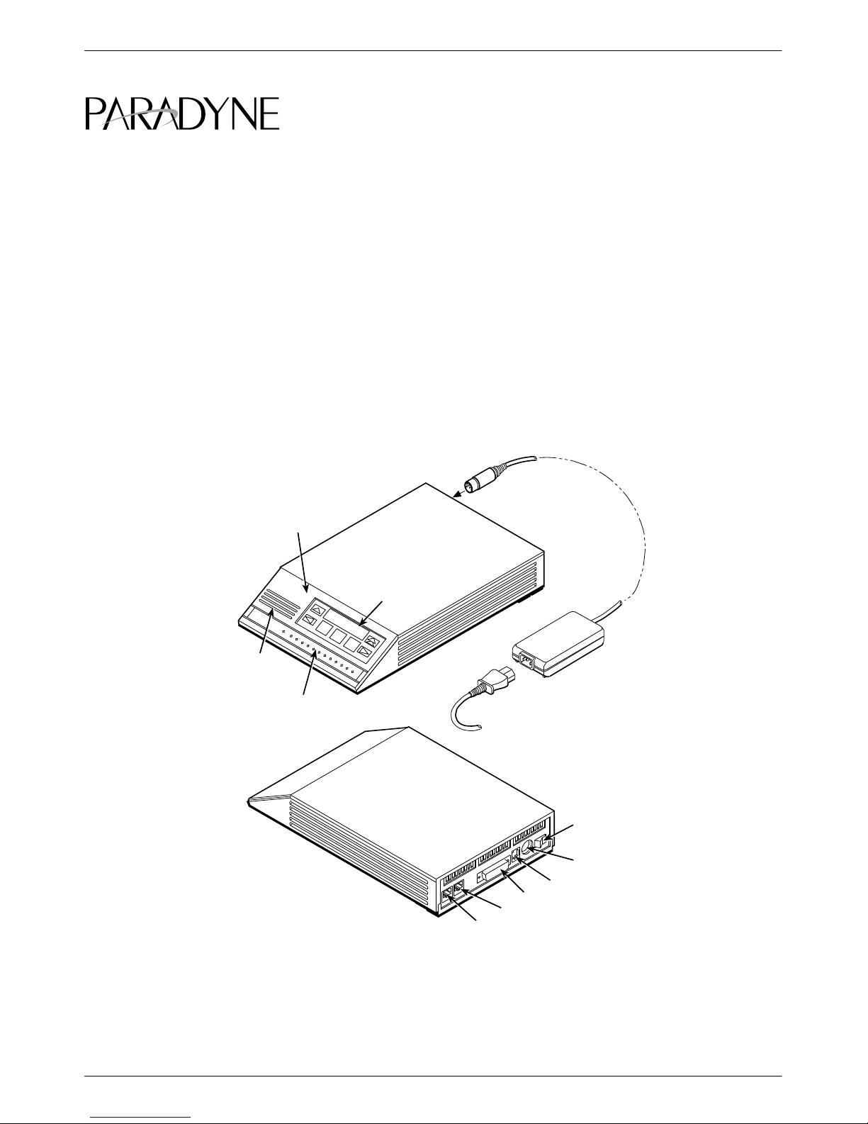
The 3820Plus modem, Model 3982-A1-401 (Figure 1),
has different installation instructions than those shown in
the COMSPHERE 3800Plus Modems User’s Guide
(3980-A2-GB30). The Model 3982-A1-401 modem has
an 8-pin modular jack for leased-line connection and a
6-pin modular jack for dial-line connection. The model
DIAGNOSTIC
CONTROL
PANEL
LCD AND
KEYPAD
shown in the User’s Guide has a single jack for leased-line
or dial-line connection.
Use these instructions to install your modem, and keep
them with your User’s Guide.
SPEAKER
STATUS
INDICAT ORS
Figure 1. 3820
POWER
CORD
DIAL
LEASED
Plus
Modem (Model 3982-A1-401)
POWER
SUPPLY
POWER
ON/OFF
POWER IN
NMS
DTE 1
496-14160-0
1
Page 2
3820
Plus
Modem Installation
Before installing your modem, make sure your
installation site is clean and well-ventilated. Allow space
around the modem for installing cables and telephone
cords, and make sure the modem is located within reach
of the ac power outlet. The distance between your modem
and the DTE should be minimized if DTE data rates
exceed 19,200 bps. Also, low capacitance cables may be
necessary for speeds greater than 19,200 bps or distances
greater than 50 feet.
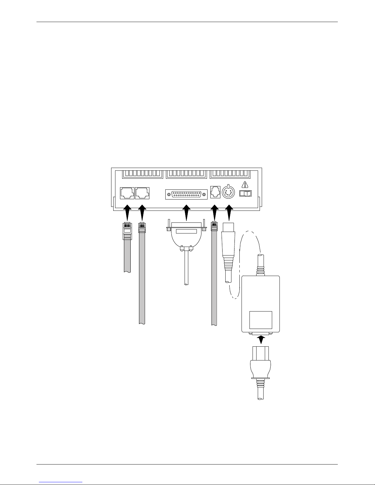
The rear panel of the 3820Plus modem has the
following switches and connectors (see Figure 2):
• An ON/Off power switch.
• An 8-pin DIN type power receptacle for the
table-top power supply.
• An 8-pin modular keyed jack for 2-wire leased
lines.
• A 6-pin modular keyed jack for dial (PSTN) lines.
• A 4-pin modular jack for network management
system (NMS) connection.
• A 25-pin DB-25-S receptacle for DTE interface.
DTE 1LEASED DIAL NMS PWR ON OFF
8-POSITION
PLUG FOR
LEASED-LINE
NETWORK
OPERATION
6-POSITION PLUG
FOR PERMISSIVE
DIAL NETWORK
OPERATION
DB-25-P
CONNECTOR
FOR DATA
TERMINAL
EQUIPMENT
OPERATION
SUB-MINIA TURE,
4-CONDUCTOR
PLUG FOR
NETWORK
MANAGEMENT
SYSTEM
OPERATION
POWER
SUPPLY
POWER
CORD
Figure 2. 3820
Plus
(Model 3982-A1-401) Rear Panel
2
Page 3

DTE Connection
Use the following procedure to connect the RS-232D
cable from the modem to the DTE:
1. Make sure the modem’s rear panel power switch is
Off.
2. Connect the DB-25-P (male) connector on the
cable to the DB-25-S (female) connector labeled
DTE 1 (Figure 2) on the modem’s rear panel. Use
a small screwdriver to tighten the cable to the
modem.
3. Connect the DB-25-P connector on the cable to
the DB-25-S connector on the DTE. Use a small
screwdriver to tighten the cable to the DTE.
Connecting 3820
Plus
Modems
with Supplied Cables
Figure 2 shows how 3820Plus modems are connected
to certain TELCO jack types using the supplied cables.
For other TELCO connections, refer to Appendix D of the
COMSPHERE 3800Plus Modems User’s Guide.
3820
Plus
2-Wire Leased-Line Network
Connection
Use the following procedure to connect a 3820Plus
modem to the leased-line network interface:
1. Insert the 8-position, 8-conductor modular plug
into the jack labeled LEASED (Figure 2).
2. Insert the other end of the modular cord into the
leased-line network interface (“demarc”).
AC Power Supply Connection
WARNING
Power supplies from other
modems may fit into the DIN
jack, but connecting the
wrong power supply can
cause damage to the modem
or the power supply.
3820
Plus
Dial-Line Connection
Use the following procedure to connect the 3820Plus
modem to the dial network interface:
1. Insert the 6-position, 4-conductor modular plug
into the jack labeled DIAL (Figure 2).
2. Insert the other end of the modular cord into the
dial network interface (“demarc”).
Use the following procedure to connect the modem to
an ac power outlet:
1. Make sure the modem’s power switch is in the Off
position.
2. Insert the power transformer’s 8-pin DIN male
connector into the modem’s rear panel power
receptacle (Figure 2).
3. Connect the power supply to a grounded ac power
outlet.
3
Page 4

Network Management System
Connection
Use the following procedure to connect the modem to
the network management system interface:
1. Insert the subminiature 4-conductor modular plug
of the 3600 Hubbing Device (Figure 3) into the
jack labeled NMS (Figure 2).
begins a power-up self-test. This test takes several
seconds to perform, and verifies the operation of most
hardware components within the modem. If successful,
the LCD displays Power On Selftst Passed and continues
to the Top-Level menu screen.
Power On Selftst
Passed
2. Connect the 3600 Hubbing Device to the network
management system.
Refer to the 3600 Hubbing Device, Feature Number
3600-F3-300, Installation Instructions for more
information. Installation for the 3820Plus modem is the
same as for the 3610 DSU.
Modem Power-Up
Once your modem is properly connected to the DTE,
dial and/or leased lines, and ac outlet, press the modem’s
rear panel power switch to the ON position. The modem
Hubbing Device
CC OUT/DC IN
CC IN/DC OUT
8-Pin
Modular
Jacks
Pin
Numbers
CC IN/DC OUT
8
1
8
3000HUBBING DEVICE
MODEL #3000-F3-300
CC OUT/DC IN
1
F1
F2
F3
If a failure occurs during the self-test, the LCD may
display Power On Selftst Failed for several seconds. The
LCD then may display the T op-Level menu screen with
the message Power on Fail appearing on the top line of
the LCD. Although a failure has occurred, the modem
may attempt to operate. If it does, you can activate a more
thorough self-test using the T est branch. Refer to
Chapter 6, Test Branch, in the COMSPHERE 3800Plus
Modems User’s Guide.
6 Inches
4-Pin
Modular
Plug
Overall
496-13775-03
Figure 3. 3600 Hubbing Device
4
 Loading...