

Paradyne COMSPHERE 3610, COMSPHERE 3611, COMSPHERE 3600 Owner's Manual

COMSPHERE
3600 SERIES
DATA SERVICE UNITS
MODELS 3610 AND 3611
OPERATOR’S GUIDE
Document No. 3610-A2-GB91-90
July 1999

COMSPHERE 3600 Series Data Service Units
COMSPHERE
3600 Series Data Service Unit
Models 3610 and 3611
Operator’s Guide
3610-A2-GB91-90
12th Edition (July 1999)
Changes and enhancements to the product and to the information herein will be documented and issued as a new release.
United States
FCC Registration number: AW292J-61661-DD-N
PSTN Ringer Equivalence number (REN): DBM option 0.7B
Canada
V.32 Dial Backup Module
Certification number: 230 3684 A
DOC Load number: 7
2-Wire Switched 56 DBM
Certification number: 230 5870 A
DOC Load number: 0
Warranty, Sales, Service, and Training Information
Contact your local sales representative, service representative, or distributor directly for any help needed. For additional information
concerning warranty, sales, service, repair, installation, documentation, training, distributor locations, or Paradyne worldwide office
locations, use one of the following methods:
• Internet: Visit the Paradyne World Wide Web site at www.paradyne.com. (Be sure to register your warranty there. Select
Technical Support → Warranty Registration.)
• Telephone: Call our automated system to receive current information by fax or to speak with a company representative.
— Within the U.S.A., call 1-800-870-2221
— Outside the U.S.A., call 1-727-530-2340
Document Feedback
We welcome your comments and suggestions about this document. Please mail them to Technical Publications, Paradyne Corporation,
8545 126th Ave. N., Largo, FL 33773, or send e-mail to userdoc@paradyne.com. Include the number and title of this document in
your correspondence. Please include your name and phone number if you are willing to provide additional clarification.
Trademarks
All products and services mentioned herein are the trademarks, service marks, registered trademarks or registered service marks of their
respective owners.
Printed on recycled paper
COPYRIGHT 1999 Paradyne Corporation. All rights reserved.
This publication is protected by federal copyright law. No part of this publication may be copied or distributed, transmitted, transcribed, stored in a retrieval system,
or translated into any human or computer language in any form or by any means, electronic, mechanical, magnetic, manual or otherwise, or disclosed to third parties
without the express written permission of Paradyne Corporation, 8545 126th Avenue North, P.O. Box 2826, Largo, Florida 33779-2826.
Paradyne Corporation makes no representation or warranties with respect to the contents hereof and specifically disclaims any implied warranties of merchantability
or fitness for a particular purpose. Further, Paradyne Corporation reserves the right to revise this publication and to make changes from time to time in the contents
hereof without obligation of Paradyne Corporation to notify any person of such revision or changes.
A July 1999 3610-A2-GB91-90

!
Important Safety Instructions
1. Read and follow all warning notices and instructions marked on the product or
included in the manual.
2. This product is intended to be used with a three-wire grounding type plug — a plug
which has a grounding pin. This is a safety feature. Equipment grounding is vital to
ensure safe operation. Do not defeat the purpose of the grounding type plug by
modifying the plug or using an adaptor.
Prior to installation, use an outlet tester or a voltmeter to check the ac receptacle for
the presence of earth ground. If the receptacle is not properly grounded, the
installation must not continue until a qualified electrician has corrected the problem.
If a three-wire grounding type power source is not available, consult a qualified
electrician to determine another method of grounding the equipment.
3. Slots and openings in the cabinet are provided for ventilation. To ensure reliable
operation of the product and to protect it from overheating, these slots and openings
must not be blocked or covered.
4. Do not allow anything to rest on the power cord and do not locate the product where
persons will walk on the power cord.
Safety Instructions
5. Do not attempt to service this product yourself, as opening or removing covers may
expose you to dangerous high voltage points or other risks. Refer all servicing to
qualified service personnel.
6. General purpose cables are provided with this product. Special cables, which may be
required by the regulatory inspection authority for the installation site, are the
responsibility of the customer.
7. When installed in the final configuration, the product must comply with the applicable
Safety Standards and regulatory requirements of the country in which it is installed. If
necessary, consult with the appropriate regulatory agencies and inspection
authorities to ensure compliance.
8. A rare phenomenon can create a voltage potential between the earth grounds of two
or more buildings. If products installed in separate buildings are interconnected, the
voltage potential may cause a hazardous condition. Consult a qualified electrical
consultant to determine whether or not this phenomenon exists and, if necessary,
implement corrective action prior to interconnecting the products.
In addition, if the equipment is to be used with telecommunications circuits, take the
following precautions:
– Never install telephone wiring during a lightning storm.
– Never install telephone jacks in wet locations unless the jack is specifically designed
for wet locations.
– Never touch uninsulated telephone wires or terminals unless the telephone line has
been disconnected at the network interface.
– Use caution when installing or modifying telephone lines.
– Avoid using a telephone (other than a cordless type) during an electrical storm.
There may be a remote risk of electric shock from lightning.
– Do not use the telephone to report a gas leak in the vicinity of the leak.
B3610-A2-GB91-90 July 1999

COMSPHERE 3600 Series Data Service Units
Notices
! ! ! ! !
!
! !!
C July 1999 3610-A2-GB91-90

Government Requirements
Certain governments require that instructions pertaining to connection to the telephone network be
included in the installation and operation manual. Specific instructions are listed in the following
sections.
United States
Notice to Users of the Telephone Network
This equipment complies with Part 68 of the FCC rules. On the bottom of the equipment is a label
or silk-screened text that contains, among other information, the FCC registration number and
Ringer Equivalence Number (REN) for this equipment. If requested, please provide this
information to your telephone company.
The REN is useful to determine the quantity of devices you may connect to your telephone line
and still have all of those devices ring when your number is called. In most, but not all areas, the
sum of the RENs of all devices should not exceed 5. T o be certain of the number of devices you
may connect to your line, as determined by the REN, you should call your local telephone
company to ascertain the maximum REN for your calling area.
Safety Instructions
If your Model 3610 or 3611 DSU (with DBM) causes harm to the telephone network, the
telephone company may discontinue your service temporarily. If possible, they will notify you in
advance. But if advance notice is not practical, you will be notified as soon as possible. You will be
advised of your right to file a complaint with the FCC.
Your telephone company may make changes in its facilities, equipment, operations, or procedures
that could affect the proper operation of your equipment. If so, you will be given advance notice so
as to give you an opportunity to maintain uninterrupted service.
The DBM cannot be used on public coin-operated telephone service provided by the telephone
company . Connection to party-line service is subject to state tariffs. (Contact the state public utility
commission, public service commission, or corporation commission for information.)
No repairs may be performed by the user. Should you experience difficulty with this equipment,
refer to the Equipment Warranty and Support section of Chapter 1 in the COMSPHERE
3600 Series Data Service Units, Models 3610 and 3611, Dial Backup Module and SNA Diagnostic
Interface Options, User’s Guide, which is shipped with the 3610 DSU.
For Digital Data Service (DDS) installations, inform the local telephone company of the
appropriate network channel interface code for the service you desire.
DDS
Interface
Code
04DU5-24 2400
04DU5-48 4800
Data Rate
(bps)
04DU5-96 9600
04DU5-19 19,200
04DU5-56 56,000
04DU5-64 64,000
D3610-A2-GB91-90 July 1999

COMSPHERE 3600 Series Data Service Units
The DDS Service Order Number is 6.0Y. The jack configurations required are RJ48S for the
Model 3610 DSU and RJ48T for the Model 3611. With an RJ48T configuration, you must specify
the number of data lines you require. Refer to the Technical Specifications section of Chapter 1 for
V.32 DBM jack information.
After the telephone company has installed the requested jack, you can connect the DSU with the
appropriate cable (provided). An FCC-compliant telephone cord and modular plug is provided
with this equipment. This equipment is designed to be connected to the telephone network or
premises wiring using a compatible modular jack that is Part 68 compliant.
Canada
Notice to Users of the Canadian Telephone Network
The Canadian Department of Communications has certified that this equipment meets certain
telecommunications network protective, operational, and safety requirements. The Department
does not guarantee that the equipment will operate to the user’s satisfaction.
Before installation, you should make sure that it is permissible to connect this equipment to the
local telecommunications company’s facilities. The equipment must be connected by an acceptable
method. In some cases the telecommunications company’s inside wiring associated with single-line
individual service may be extended with a certified connector assembly (telephone connection
cord). The customer should be aware that compliance with the above conditions may not prevent
degradation of service in some situations.
If you experience difficulty with this equipment and require service, refer to the Equipment
Warranty and Support section of Chapter 1 in the COMSPHERE 3600 Series Data Service Units,
Models 3610 and 3611, Dial Backup Module and SNA Diagnostic Interface Options, User’s Guide,
which is shipped with the DSU.
Repairs to certified equipment should be made by an authorized Canadian maintenance facility.
Any repairs or alterations made by the user to this equipment, or equipment malfunctions, may
cause the telecommunications company to ask you to disconnect the equipment.
Users should ensure for their own protection that the electrical ground connections of the power
utility, telephone lines and internal metallic water pipe system, if present, are connected together.
This precaution may be particularly important in rural areas.
CAUTION
Users should not attempt to make such connections themselves,
but should contact the appropriate electric inspection authority,
or an electrician, as appropriate.
The load number (LN) is labeled on the equipment. The LN denotes the percentage of the total
load to be connected to a telephone loop used by this equipment. T o prevent an overload, the total
of the LNs of all devices attached to the loop may not exceed 100. The LN also specifies the
appropriate ringing type (A or B), if applicable. For example, LN = 20A designates a load number
of 20 and an “A” type ringer.
E July 1999 3610-A2-GB91-90

Table of Contents
Preface
About this Guide vii. . . . . . . . . . . . . . . . . . . . . . . . . . . . . . . . . . . . . . . . . .
How to Use this Guide vii. . . . . . . . . . . . . . . . . . . . . . . . . . . . . . . . . . . . . .
Related Documents viii. . . . . . . . . . . . . . . . . . . . . . . . . . . . . . . . . . . . . . . .
Reference Documents ix. . . . . . . . . . . . . . . . . . . . . . . . . . . . . . . . . . . . . .
1. Introduction
Overview 1-1. . . . . . . . . . . . . . . . . . . . . . . . . . . . . . . . . . . . . . . . . . . . . . . .
Feature Overview 1-2. . . . . . . . . . . . . . . . . . . . . . . . . . . . . . . . . . . . . . . . . .
Optional Features 1-3. . . . . . . . . . . . . . . . . . . . . . . . . . . . . . . . . . . . . . . . . .
Feature Description 1-4. . . . . . . . . . . . . . . . . . . . . . . . . . . . . . . . . . . . . . . .
T echnical Specifications 1-27. . . . . . . . . . . . . . . . . . . . . . . . . . . . . . . . . . . .
Equipment Warranty and Support 1-40. . . . . . . . . . . . . . . . . . . . . . . . . . . . .
2. Model 3610 Installation
Overview 2-1. . . . . . . . . . . . . . . . . . . . . . . . . . . . . . . . . . . . . . . . . . . . . . . .
Installation Planning 2-2. . . . . . . . . . . . . . . . . . . . . . . . . . . . . . . . . . . . . . .
Hardware Straps 2-3. . . . . . . . . . . . . . . . . . . . . . . . . . . . . . . . . . . . . . . . . . .
Model 3610 DSU Installation 2-4. . . . . . . . . . . . . . . . . . . . . . . . . . . . . . . .
Electrical Connection 2-6. . . . . . . . . . . . . . . . . . . . . . . . . . . . . . . . . . . . . . .
Network Diagnostic Connection 2-8. . . . . . . . . . . . . . . . . . . . . . . . . . . . . .
Async T erminal Connection 2-9. . . . . . . . . . . . . . . . . . . . . . . . . . . . . . . . . .
Software Configuration 2-9. . . . . . . . . . . . . . . . . . . . . . . . . . . . . . . . . . . . .
DDS (or LADS) Network Connection 2-10. . . . . . . . . . . . . . . . . . . . . . . . . .
LADS Connection 2-10. . . . . . . . . . . . . . . . . . . . . . . . . . . . . . . . . . . . . . . . .
DSU DTE Connection 2-11. . . . . . . . . . . . . . . . . . . . . . . . . . . . . . . . . . . . . .
Verification Testing 2-11. . . . . . . . . . . . . . . . . . . . . . . . . . . . . . . . . . . . . . . .
Replacing Firmware of an Installed Model 3610 DSU 2-12. . . . . . . . . . . . .
3. Model 3611 Installation
Overview 3-1. . . . . . . . . . . . . . . . . . . . . . . . . . . . . . . . . . . . . . . . . . . . . . . .
Installation Planning 3-2. . . . . . . . . . . . . . . . . . . . . . . . . . . . . . . . . . . . . . .
Hardware Straps 3-2. . . . . . . . . . . . . . . . . . . . . . . . . . . . . . . . . . . . . . . . . . .
Model 3611 DSU Installation 3-5. . . . . . . . . . . . . . . . . . . . . . . . . . . . . . . .
Network Diagnostic Connection 3-9. . . . . . . . . . . . . . . . . . . . . . . . . . . . . .
Software Configuration 3-9. . . . . . . . . . . . . . . . . . . . . . . . . . . . . . . . . . . . .
DDS Network Connection 3-10. . . . . . . . . . . . . . . . . . . . . . . . . . . . . . . . . . .
i3610-A2-GB91-90 July 1999

COMSPHERE 3600 Series Data Service Units
4. DSU Operations
5. Operation Verification
LADS Connection 3-10. . . . . . . . . . . . . . . . . . . . . . . . . . . . . . . . . . . . . . . . .
DSU DTE Connection 3-11. . . . . . . . . . . . . . . . . . . . . . . . . . . . . . . . . . . . . .
Verification Testing 3-12. . . . . . . . . . . . . . . . . . . . . . . . . . . . . . . . . . . . . . . .
Replacing Firmware of an Installed Model 3611 DSU 3-12. . . . . . . . . . . . .
Overview 4-2. . . . . . . . . . . . . . . . . . . . . . . . . . . . . . . . . . . . . . . . . . . . . . . .
Diagnostic Control Panel 4-2. . . . . . . . . . . . . . . . . . . . . . . . . . . . . . . . . . . .
Menu Structure 4-6. . . . . . . . . . . . . . . . . . . . . . . . . . . . . . . . . . . . . . . . . . . .
Status Branch 4-8. . . . . . . . . . . . . . . . . . . . . . . . . . . . . . . . . . . . . . . . . . . . .
Backup Branch 4-13. . . . . . . . . . . . . . . . . . . . . . . . . . . . . . . . . . . . . . . . . . . .
T est Branch 4-14. . . . . . . . . . . . . . . . . . . . . . . . . . . . . . . . . . . . . . . . . . . . . .
Configuration Branch 4-29. . . . . . . . . . . . . . . . . . . . . . . . . . . . . . . . . . . . . . .
Control Branch 4-35. . . . . . . . . . . . . . . . . . . . . . . . . . . . . . . . . . . . . . . . . . . .
Messages Branch 4-39. . . . . . . . . . . . . . . . . . . . . . . . . . . . . . . . . . . . . . . . . .
Overview 5-1. . . . . . . . . . . . . . . . . . . . . . . . . . . . . . . . . . . . . . . . . . . . . . . .
MCMP Initialization Procedure 5-1. . . . . . . . . . . . . . . . . . . . . . . . . . . . . . .
Verification Procedure 5-2. . . . . . . . . . . . . . . . . . . . . . . . . . . . . . . . . . . . . .
6. Configuration Options
Overview 6-1. . . . . . . . . . . . . . . . . . . . . . . . . . . . . . . . . . . . . . . . . . . . . . . .
Option Sets 6-1. . . . . . . . . . . . . . . . . . . . . . . . . . . . . . . . . . . . . . . . . . . . . . .
Using the DCP to Set Configuration Options 6-2. . . . . . . . . . . . . . . . . . . .
Appendices
A. Data Service Unit Menu A-1. . . . . . . . . . . . . . . . . . . . . . . . . . . . . . . . .
B. Configuration Worksheets B-1. . . . . . . . . . . . . . . . . . . . . . . . . . . . . . .
C. Diagnostic Control Panel Messages Reference C-1. . . . . . . . . . . . . . .
D. Async T erminal Operation D-1. . . . . . . . . . . . . . . . . . . . . . . . . . . . . . .
E. Network Management Connectivity E-1. . . . . . . . . . . . . . . . . . . . . . .
F. Pin Assignments F-1. . . . . . . . . . . . . . . . . . . . . . . . . . . . . . . . . . . . . . .
G. Troubleshooting G-1. . . . . . . . . . . . . . . . . . . . . . . . . . . . . . . . . . . . . . .
H. NMS Commands Reference H-1. . . . . . . . . . . . . . . . . . . . . . . . . . . . .
I. DATAPHONE II NMS Options I -1. . . . . . . . . . . . . . . . . . . . . . . . . . .
J. DMC NMS Options J -1. . . . . . . . . . . . . . . . . . . . . . . . . . . . . . . . . . . .
K. DMC Commands K-1. . . . . . . . . . . . . . . . . . . . . . . . . . . . . . . . . . . . . .
L. Equipment Lists L-1. . . . . . . . . . . . . . . . . . . . . . . . . . . . . . . . . . . . . . .
Glossary
Index
ii July 1999 3610-A2-GB91-90

Table of Contents
List of Figures
Figure Page
1-1 Single-Port Point-to-Point Circuit with Nondisruptive Diagnostics 1-5. . . . . . . . . . .
1-2 Single-Port Multipoint Circuit with Nondisruptive Diagnostics 1-7. . . . . . . . . . . . . .
1-3 Multipoint Async-Compatible Network 1-8. . . . . . . . . . . . . . . . . . . . . . . . . . . . . . . .
1-4 NMS Interfaces to the SDU 1-11. . . . . . . . . . . . . . . . . . . . . . . . . . . . . . . . . . . . . . . . . .
1-5 Sample Diagnostic Configuration 1-23. . . . . . . . . . . . . . . . . . . . . . . . . . . . . . . . . . . . .
1-6 Aggregate Switched Backup for a Point-to-Point Configuration 1-24. . . . . . . . . . . . .
1-7 Aggregate Switched Backup for a Multipoint Configuration 1-25. . . . . . . . . . . . . . . .
1-8 External DTE Lead Control of Backup 1-26. . . . . . . . . . . . . . . . . . . . . . . . . . . . . . . . .
2-1 Model 3610 DSU Hardware Switch Location 2-4. . . . . . . . . . . . . . . . . . . . . . . . . . . .
2-2 Model 3610 Circuit Card Switch and Jumper Locations 2-5. . . . . . . . . . . . . . . . . . . .
2-3 Model 3610 DSU Electrical Connection 2-7. . . . . . . . . . . . . . . . . . . . . . . . . . . . . . . .
2-4 Model 3610 DSU NMS Connection 2-8. . . . . . . . . . . . . . . . . . . . . . . . . . . . . . . . . . .
2-5 Model 3610 DSU Async T erminal 2-9. . . . . . . . . . . . . . . . . . . . . . . . . . . . . . . . . . . .
2-6 Model 3610 DSU DDS Network Connection 2-10. . . . . . . . . . . . . . . . . . . . . . . . . . . .
3-1 Non-Modular Model 3611 Circuit Card Switch and Jumper Locations 3-3. . . . . . . .
3-2 Modular 3611 Circuit Card Switch and Jumper Locations 3-4. . . . . . . . . . . . . . . . . .
3-3 Model 3611 DSU Installation and Circuit Pack Lock 3-5. . . . . . . . . . . . . . . . . . . . . .
3-4 COMSPHERE 3000 Series Carrier, Rear View 3-6. . . . . . . . . . . . . . . . . . . . . . . . . . .
3-5 Modular DSU V.35 Adapter Installation 3-8. . . . . . . . . . . . . . . . . . . . . . . . . . . . . . . .
4-1 Model 3610 DCP 4-2. . . . . . . . . . . . . . . . . . . . . . . . . . . . . . . . . . . . . . . . . . . . . . . . . .
4-2 SDCP and Model 3611 DSU Faceplate 4-3. . . . . . . . . . . . . . . . . . . . . . . . . . . . . . . . .
4-3 Device T est 4-16. . . . . . . . . . . . . . . . . . . . . . . . . . . . . . . . . . . . . . . . . . . . . . . . . . . . . . .
4-4 Local Loopback 4-17. . . . . . . . . . . . . . . . . . . . . . . . . . . . . . . . . . . . . . . . . . . . . . . . . . .
4-5 DTE Loopback 4-18. . . . . . . . . . . . . . . . . . . . . . . . . . . . . . . . . . . . . . . . . . . . . . . . . . . .
4-6 Digital Loopback 4-19. . . . . . . . . . . . . . . . . . . . . . . . . . . . . . . . . . . . . . . . . . . . . . . . . .
4-7 Remote Digital Loopback 4-20. . . . . . . . . . . . . . . . . . . . . . . . . . . . . . . . . . . . . . . . . . .
4-8 Bilateral Loopback 4-21. . . . . . . . . . . . . . . . . . . . . . . . . . . . . . . . . . . . . . . . . . . . . . . . .
4-9 Digital T est 4-22. . . . . . . . . . . . . . . . . . . . . . . . . . . . . . . . . . . . . . . . . . . . . . . . . . . . . . .
4-10 End-to-End Test 4-25. . . . . . . . . . . . . . . . . . . . . . . . . . . . . . . . . . . . . . . . . . . . . . . . . . .
4-11 Bit Error Rate Test 4-27. . . . . . . . . . . . . . . . . . . . . . . . . . . . . . . . . . . . . . . . . . . . . . . . .
D-1 Password Access Menu Screen D-3. . . . . . . . . . . . . . . . . . . . . . . . . . . . . . . . . . . . . . .
D-2 Top-Level Menu Screen D-4. . . . . . . . . . . . . . . . . . . . . . . . . . . . . . . . . . . . . . . . . . . . .
D-3 Second-Level Menu Screen D-5. . . . . . . . . . . . . . . . . . . . . . . . . . . . . . . . . . . . . . . . . .
D-4 Configure Menu Selection Screen D-5. . . . . . . . . . . . . . . . . . . . . . . . . . . . . . . . . . . . .
D-5 Control Function Menu Selection Screen D-6. . . . . . . . . . . . . . . . . . . . . . . . . . . . . . .
D-6 External Leads Menu Selection Screen D-7. . . . . . . . . . . . . . . . . . . . . . . . . . . . . . . . .
D-7 External Leads Input Screen D-7. . . . . . . . . . . . . . . . . . . . . . . . . . . . . . . . . . . . . . . . .
D-8 Async Terminal Menu Screen D-9. . . . . . . . . . . . . . . . . . . . . . . . . . . . . . . . . . . . . . . .
D-9 Customer ID Menu Screen D-9. . . . . . . . . . . . . . . . . . . . . . . . . . . . . . . . . . . . . . . . . . .
iii3610-A2-GB91-90 July 1999

COMSPHERE 3600 Series Data Service Units
Figure Page
D-10 Customer ID Input Screen D-10. . . . . . . . . . . . . . . . . . . . . . . . . . . . . . . . . . . . . . . . . . .
D-11 Customer ID Confirmation Screen D-10. . . . . . . . . . . . . . . . . . . . . . . . . . . . . . . . . . . .
D-12 Password Menu Screen D-11. . . . . . . . . . . . . . . . . . . . . . . . . . . . . . . . . . . . . . . . . . . . .
D-13 Password Input Screen D-12. . . . . . . . . . . . . . . . . . . . . . . . . . . . . . . . . . . . . . . . . . . . .
D-14 AntiStream Menu Screen D-13. . . . . . . . . . . . . . . . . . . . . . . . . . . . . . . . . . . . . . . . . . . .
D-15 AntiStream Input Screen D-13. . . . . . . . . . . . . . . . . . . . . . . . . . . . . . . . . . . . . . . . . . . .
D-16 DSU Tests Selection Screen D-14. . . . . . . . . . . . . . . . . . . . . . . . . . . . . . . . . . . . . . . . . .
D-17 DSU Digital T est Selection Screen D-15. . . . . . . . . . . . . . . . . . . . . . . . . . . . . . . . . . . .
D-18 Port Number Selection Screen D-15. . . . . . . . . . . . . . . . . . . . . . . . . . . . . . . . . . . . . . . .
D-19 DSU Digital T est Run Time Input Screen D-16. . . . . . . . . . . . . . . . . . . . . . . . . . . . . . .
D-20 Digital Test Completion Screen D-16. . . . . . . . . . . . . . . . . . . . . . . . . . . . . . . . . . . . . . .
D-21 Status Menu Selection Screen D-17. . . . . . . . . . . . . . . . . . . . . . . . . . . . . . . . . . . . . . . .
D-22 Health and Status Menu Selection Screen D-18. . . . . . . . . . . . . . . . . . . . . . . . . . . . . . .
D-23 Device Health and Status Display Screen D-18. . . . . . . . . . . . . . . . . . . . . . . . . . . . . . .
D-24 Identity Display Screen D-19. . . . . . . . . . . . . . . . . . . . . . . . . . . . . . . . . . . . . . . . . . . . .
E-1 Control Channel E-2. . . . . . . . . . . . . . . . . . . . . . . . . . . . . . . . . . . . . . . . . . . . . . . . . . .
E-2 Extended Control Channel E-3. . . . . . . . . . . . . . . . . . . . . . . . . . . . . . . . . . . . . . . . . . .
E-3 Diagnostic Channel E-4. . . . . . . . . . . . . . . . . . . . . . . . . . . . . . . . . . . . . . . . . . . . . . . .
F-1 Digital Network Connector F-2. . . . . . . . . . . . . . . . . . . . . . . . . . . . . . . . . . . . . . . . . .
F-2 3600 Hubbing Device (3600-F3-300) F-3. . . . . . . . . . . . . . . . . . . . . . . . . . . . . . . . . .
F-3 Modular 3611 DSU 25-Pin EIA-232/25-Pin V.35
Rear Connector Plate (3000-F1-021) F-5. . . . . . . . . . . . . . . . . . . . . . . . . . . . . . . . .
F-4 Modular DSU V .35 Adapter Plug (3000-F1-511) F-7. . . . . . . . . . . . . . . . . . . . . . . . .
F-5 Modular DSU V .35 Adapter Cable (3000-F1-510) F-7. . . . . . . . . . . . . . . . . . . . . . . .
F-6 NMS Adapter Cable (3000-F2-510) F-9. . . . . . . . . . . . . . . . . . . . . . . . . . . . . . . . . . .
F-7 DSU CC-to-DB25 Async Terminal Cable (3600-F3-504) F-10. . . . . . . . . . . . . . . . . .
F-8 EIA-232-D Crossover Cable (4951-035F) F-11. . . . . . . . . . . . . . . . . . . . . . . . . . . . . .
F-9 V .35 Crossover Cable (3211-178F) F-12. . . . . . . . . . . . . . . . . . . . . . . . . . . . . . . . . . . .
G-1 Out-of-Service (OOS) Condition Troubleshooting G-2. . . . . . . . . . . . . . . . . . . . . . . .
G-2 No Signal (NS) Condition Troubleshooting G-3. . . . . . . . . . . . . . . . . . . . . . . . . . . . .
G-3 Streaming Terminal (STR) Condition Troubleshooting G-4. . . . . . . . . . . . . . . . . . . .
G-4 Out-of-Frame (OOF) Condition Troubleshooting G-5. . . . . . . . . . . . . . . . . . . . . . . . .
iv July 1999 3610-A2-GB91-90

Table of Contents
List of Tables
Table Page
1-1 LADS Connection Distances 1-4. . . . . . . . . . . . . . . . . . . . . . . . . . . . . . . . . . . . . . . . .
1-2 Valid Sync Speeds and Nondisruptive Diagnostics 1-6. . . . . . . . . . . . . . . . . . . . . . . .
1-3 V.14 DTE Overspeed/Underspeed Percentages 1-7. . . . . . . . . . . . . . . . . . . . . . . . . . .
1-4 Diagnostic Compatibilities 1-9. . . . . . . . . . . . . . . . . . . . . . . . . . . . . . . . . . . . . . . . . . .
1-5 Protocols and Addressing 1-15. . . . . . . . . . . . . . . . . . . . . . . . . . . . . . . . . . . . . . . . . . .
1-6 Conversion Table for DATAPHONE II Addresses 1-16. . . . . . . . . . . . . . . . . . . . . . . .
1-7 Conversion T able for DMC Addresses 1-18. . . . . . . . . . . . . . . . . . . . . . . . . . . . . . . . .
1-8 General 3600 Series T echnical Specifications 1-28. . . . . . . . . . . . . . . . . . . . . . . . . . . .
1-9 DSU T echnical Specifications 1-32. . . . . . . . . . . . . . . . . . . . . . . . . . . . . . . . . . . . . . . .
1-10 V.32 DBM or DBM-V Technical Specifications 1-33. . . . . . . . . . . . . . . . . . . . . . . . . .
1-11 4-Wire Switched 56 DBM or DBM-S Technical Specifications 1-35. . . . . . . . . . . . . .
1-12 2-Wire Switched 56 DBM or DBM-D Technical Specifications 1-36. . . . . . . . . . . . . .
1-13 3600 Hubbing Device Technical Specifications 1-36. . . . . . . . . . . . . . . . . . . . . . . . . .
1-14 TDM Technical Specifications 1-37. . . . . . . . . . . . . . . . . . . . . . . . . . . . . . . . . . . . . . .
1-15 MCMP Technical Specifications 1-38. . . . . . . . . . . . . . . . . . . . . . . . . . . . . . . . . . . . . .
1-16 Technical Specifications for Digital Bridge Capability 1-39. . . . . . . . . . . . . . . . . . . . .
2-1 Model 3610 DSU Switch Settings 2-3. . . . . . . . . . . . . . . . . . . . . . . . . . . . . . . . . . . . .
2-2 Model 3610 DSU Jumper Straps 2-5. . . . . . . . . . . . . . . . . . . . . . . . . . . . . . . . . . . . . .
3-1 Model 3611 DSU Switch Settings 3-3. . . . . . . . . . . . . . . . . . . . . . . . . . . . . . . . . . . . .
3-2 Model 3611 Jumper Straps 3-4. . . . . . . . . . . . . . . . . . . . . . . . . . . . . . . . . . . . . . . . . .
4-1 3600 Series DSU Status Indicators 4-4. . . . . . . . . . . . . . . . . . . . . . . . . . . . . . . . . . . .
4-2 Status Branch Menu Selections 4-8. . . . . . . . . . . . . . . . . . . . . . . . . . . . . . . . . . . . . . .
4-3 DTE Lead Status Codes 4-11. . . . . . . . . . . . . . . . . . . . . . . . . . . . . . . . . . . . . . . . . . . . .
4-4 Identity Field Descriptions 4-12. . . . . . . . . . . . . . . . . . . . . . . . . . . . . . . . . . . . . . . . . . .
4-5 T est Branch Menu Selections for the DSU 4-15. . . . . . . . . . . . . . . . . . . . . . . . . . . . . .
4-6 Digital T est Results 4-24. . . . . . . . . . . . . . . . . . . . . . . . . . . . . . . . . . . . . . . . . . . . . . . .
4-7 End-to-End Test Results 4-26. . . . . . . . . . . . . . . . . . . . . . . . . . . . . . . . . . . . . . . . . . . .
4-8 Bit Error Rate T est Results 4-28. . . . . . . . . . . . . . . . . . . . . . . . . . . . . . . . . . . . . . . . . .
4-9 Configuration Branch Menu Selections 4-29. . . . . . . . . . . . . . . . . . . . . . . . . . . . . . . . .
4-10 Default Configuration Option Sets 4-30. . . . . . . . . . . . . . . . . . . . . . . . . . . . . . . . . . . .
4-11 PList Options and Their Function 4-31. . . . . . . . . . . . . . . . . . . . . . . . . . . . . . . . . . . . .
4-12 Control Branch Menu Options 4-35. . . . . . . . . . . . . . . . . . . . . . . . . . . . . . . . . . . . . . . .
4-13 Lead States 4-38. . . . . . . . . . . . . . . . . . . . . . . . . . . . . . . . . . . . . . . . . . . . . . . . . . . . . . .
6-1 DSU Configuration Options 6-7. . . . . . . . . . . . . . . . . . . . . . . . . . . . . . . . . . . . . . . . .
6-2 Diagnostic DSU Configuration Options 6-10. . . . . . . . . . . . . . . . . . . . . . . . . . . . . . . .
6-3 Diagnostic DBM Configuration Options 6-13. . . . . . . . . . . . . . . . . . . . . . . . . . . . . . . .
6-4 Diagnostic General Configuration Options 6-14. . . . . . . . . . . . . . . . . . . . . . . . . . . . . .
6-5 DBM Configuration Options 6-17. . . . . . . . . . . . . . . . . . . . . . . . . . . . . . . . . . . . . . . . .
v3610-A2-GB91-90 July 1999

COMSPHERE 3600 Series Data Service Units
Table Page
6-6 General Configuration Options 6-23. . . . . . . . . . . . . . . . . . . . . . . . . . . . . . . . . . . . . . .
6-7 CTS Interface Lead Control 6-31. . . . . . . . . . . . . . . . . . . . . . . . . . . . . . . . . . . . . . . . . .
6-8 Backup Configuration Options 6-32. . . . . . . . . . . . . . . . . . . . . . . . . . . . . . . . . . . . . . .
6-9 TDM Setup (MUX Funct: TDM) Configuration Options 6-34. . . . . . . . . . . . . . . . . . .
6-10 MCMP Setup (MUX Funct: MCMP) Configuration Options 6-37. . . . . . . . . . . . . . . .
6-11 Digital Bridge Setup (MUX Funct: CBrdg or EBrdg) Configuration Options 6-41. . .
6-12 TDM/MCMP Port (MUX Funct: TDM or MCMP) Configuration Options 6-44. . . . .
6-13 Digital Bridge Port (MUX Funct: CBrdg or EBrdg) Configuration Options 6-49. . . .
6-14 Port Speed Configuration Options for DSU with TDM 6-52. . . . . . . . . . . . . . . . . . . .
6-15 Port Speed Configuration Options for DSU with MCMP 6-53. . . . . . . . . . . . . . . . . . .
6-16 Port Speed Configuration Options for DBM with TDM or MCMP 6-54. . . . . . . . . . .
6-17 Channel-to-Port Assignment Configuration Options for MCMP 6-55. . . . . . . . . . . . .
6-18 LPDA-2 Configuration Options 6-56. . . . . . . . . . . . . . . . . . . . . . . . . . . . . . . . . . . . . . .
C-1 DCP to Async Terminal Messages C-1. . . . . . . . . . . . . . . . . . . . . . . . . . . . . . . . . . . . .
C-2 Command Progress Messages C-2. . . . . . . . . . . . . . . . . . . . . . . . . . . . . . . . . . . . . . . .
C-3 Command Error Messages C-2. . . . . . . . . . . . . . . . . . . . . . . . . . . . . . . . . . . . . . . . . . .
C-4 Device Health and Status Messages C-3. . . . . . . . . . . . . . . . . . . . . . . . . . . . . . . . . . . .
C-5 Expanded Health and Status Messages C-8. . . . . . . . . . . . . . . . . . . . . . . . . . . . . . . . .
C-6 Subnetwork Health and Status Messages C-9. . . . . . . . . . . . . . . . . . . . . . . . . . . . . . .
C-7 Multipoint Backup Progress Messages C-10. . . . . . . . . . . . . . . . . . . . . . . . . . . . . . . . .
C-8 Point-to-Point Dial Backup Progress Messages C-11. . . . . . . . . . . . . . . . . . . . . . . . . .
C-9 Point-to-Point Dial Backup Error Messages C-12. . . . . . . . . . . . . . . . . . . . . . . . . . . . .
C-10 TDM/MCMP/Bridge Configuration Error Messages C-14. . . . . . . . . . . . . . . . . . . . . .
D-1 DCP Keypad to Async Terminal Symbols Translation D-3. . . . . . . . . . . . . . . . . . . . .
F-1 Model 3610 — Digital Network Connector
(DDS and 4-Wire Switched 56 kbps) Pin Assignments F-2. . . . . . . . . . . . . . . . . . .
F-2 Model 3610 — 6-Pin Network Connector
(V.32 DBM and 2-Wire Switched 56 kbps) Pin Assignments F-2. . . . . . . . . . . . . .
F-3 3600 Hubbing Device Pin Assignments F-3. . . . . . . . . . . . . . . . . . . . . . . . . . . . . . . .
F-4 3600 Hubbing Device CC IN/DC OUT Jack Connector Pin Assignments F-4. . . . . .
F-5 3600 Hubbing Device CC OUT/DC IN Jack Connector Pin Assignments F-4. . . . . .
F-6 EIA-232/V .24 Connector Pin Assignments F-6. . . . . . . . . . . . . . . . . . . . . . . . . . . . . .
F-7 Modular DSU 25-Pin V .35 Connector Pin Assignments F-8. . . . . . . . . . . . . . . . . . . .
F-8 NMS Adapter Cable Pin Assignments F-9. . . . . . . . . . . . . . . . . . . . . . . . . . . . . . . . . .
H-1 NMS Command Set H-2. . . . . . . . . . . . . . . . . . . . . . . . . . . . . . . . . . . . . . . . . . . . . . . .
I-1 DATAPHONE II Options Matrix I-1. . . . . . . . . . . . . . . . . . . . . . . . . . . . . . . . . . . . . .
I-2 A Options I-2. . . . . . . . . . . . . . . . . . . . . . . . . . . . . . . . . . . . . . . . . . . . . . . . . . . . . . . .
I-3 B Options I-2. . . . . . . . . . . . . . . . . . . . . . . . . . . . . . . . . . . . . . . . . . . . . . . . . . . . . . . .
I-4 C Options I-2. . . . . . . . . . . . . . . . . . . . . . . . . . . . . . . . . . . . . . . . . . . . . . . . . . . . . . . .
I-5 D Options I-3. . . . . . . . . . . . . . . . . . . . . . . . . . . . . . . . . . . . . . . . . . . . . . . . . . . . . . . .
I-6 E Options I-3. . . . . . . . . . . . . . . . . . . . . . . . . . . . . . . . . . . . . . . . . . . . . . . . . . . . . . . .
I-7 F Options I-3. . . . . . . . . . . . . . . . . . . . . . . . . . . . . . . . . . . . . . . . . . . . . . . . . . . . . . . .
I-8 G Options I-4. . . . . . . . . . . . . . . . . . . . . . . . . . . . . . . . . . . . . . . . . . . . . . . . . . . . . . . .
I-9 H Options I-4. . . . . . . . . . . . . . . . . . . . . . . . . . . . . . . . . . . . . . . . . . . . . . . . . . . . . . . .
I-10 I Options I-4. . . . . . . . . . . . . . . . . . . . . . . . . . . . . . . . . . . . . . . . . . . . . . . . . . . . . . . . .
I-11 Valid General/DSU Options I-5. . . . . . . . . . . . . . . . . . . . . . . . . . . . . . . . . . . . . . . . . .
I-12 Valid DBM/Backup Options I-5. . . . . . . . . . . . . . . . . . . . . . . . . . . . . . . . . . . . . . . . .
J-1 DSU Options J-1. . . . . . . . . . . . . . . . . . . . . . . . . . . . . . . . . . . . . . . . . . . . . . . . . . . . .
K-1 ANALYSIS 6510 NMS DMC Commands K-1. . . . . . . . . . . . . . . . . . . . . . . . . . . . . .
vi July 1999 3610-A2-GB91-90

Preface
About this Guide
This operator’s guide contains installation and
operation information for the COMSPHEREr 3600 Series
Data Service Units (DSUs), Models 3610 and 3611. The
Model 3610 is a standalone unit while the Model 3611 is
carrier-mounted.
There are two types of Model 3611 DSUs, modular and
non-modular. The Modular 3611 DSU has contacts at the
rear of the circuit card. The contacts plug into the
COMSPHERE 3000 Series Carrier, allowing the circuit
card to be removed without having to disconnect the DTE
cables. The non-modular Model 3611 DSU has connectors
mounted onto its circuit card; however, the DTE cables
must be disconnected before the DSU can be removed
from the carrier. In this guide, references to the
Model 3611 DSU (or to the carrier-mounted DSU) apply
to either the modular or non-modular 3611 DSU, unless
otherwise specified.
It is assumed that you are familiar with the functional
operation of digital data communications equipment.
Order the COMSPHERE 3600 Series Data Service
Units, Models 3610 and 3611, Dial Backup Module and
SNA Diagnostic Interface Options, Applications Guide if
the Dial Backup Module (DBM) or SNA Diagnostic
Interface options are part of your configuration.
Order the COMSPHERE 3600 Series Data Service
Units, Models 3610 and 3611, Time Division Multiplexer,
Multichannel Multipoint, and Digital Bridge Options,
Applications Guide if your application uses a TDM or
MCMP circuit card, or uses DBM-Vs, DBM-Ss, or
DBM-Ds. The SNA Diagnostic Interface option, as it
applies to these applications, is also covered in this guide.
How to Use this Guide
Chapter 1 gives a general overview of the 3600 Series
DSU. Refer to this chapter for a summary of feature
capability and the technical specifications. (Refer to the
front matter of this guide for equipment return and
applicable government requirements information.)
Chapter 2 explains how to install and set up a
Model 3610 DSU (standalone DSU).
Chapter 3 explains how to install and set up a
Model 3611 DSU (carrier-mounted DSU).
Chapter 4 gives an overview of how to operate the
DCP and to understand the DSU’s status indicators.
Chapter 4 also provides an overview of the DSU’s menu
structure, with a brief description of each branch’s
purpose or function.
Chapter 5 explains how to verify operation of the DSU
and its options using the DCP.
Chapter 6 provides the basics of setting or changing
configuration options. Use the Configuration Option
T ables to assist you in making appropriate selections when
a change to the factory-loaded configuration options may
be required.
Appendix A provides a summary of the DSU’s menu
structure. Refer to the menu tree as you proceed through
the menu via the DCP (or SDCP if you have a Model
3611 DSU).
Appendix B provides a summary of all of the
configuration options in the form of Configuration
Worksheets, along with a suggestion for how the
worksheets can be used.
vii3610-A2-GB91-70 July 1999

COMSPHERE 3600 Series Data Service Units
Appendix C explains when the DSU issues a message.
The following message types are explained: command
progress and error messages; device, expanded, and
subnetwork health and status messages; point-to-point and
multipoint dial backup messages; TDM, MCMP, and
digital bridge configuration error messages.
Appendix D provides details regarding async terminal
operation.
Appendix E provides DSU cables related to NMS.
Appendix F provides pin assignments for DSU
connectors, cables, and its hubbing device; Appendix G
provides troubleshooting information for the DSU and its
options.
Appendices H through K provide NMS information.
Appendix L provides a complete equipment list for the
DSU and its options.
The Glossary defines some of the acronyms and
product-specific terms used in connection with the
3600 Series DSU and its options.
Related Documents
Basic DSU product documentation includes the
following:
3610-A2-GB46 COMSPHERE 3600 Series
Data Service Units, Models
3610 and 3611, User’s Guide
3610-A2-GB48 COMSPHERE 3600 Series
Data Service Units, Models
3610 and 3611, Time Division
Multiplexer, Multichannel
Multipoint, and Digital Bridge
Options, User’s Guide
Supplement
Should more detail about how the DSU operates be
required, the following additional documentation also may
be ordered:
3610-A2-GN32 COMSPHERE 3600 Series
Data Service Units, Models
3610 and 3611, Dial Backup
Module and SNA Diagnostic
Interface Options, Applications
Guide
Other product documentation includes the following:
3000-A2-GA31 COMSPHERE 3000 Series
Carrier, Installation Manual
3000-A2-GB41 COMSPHERE –48 Vdc
Central Office Power Unit,
Installation Guide
3610-A2-GB42 COMSPHERE 3600 Series
Data Services Units, Models
3610 and 3611, Secondary
Channel Applications
Supplement
6700-A2-GB41 COMSPHERE 6700 Series
Network Management System,
User’s Guide, Security
Manager Feature Supplement
6700-A2-GY31 COMSPHERE 6700 Series
Network Management System,
User’s Guide
6800-A2-GB31 COMSPHERE 6800 Series
Network Management System,
Communications Products
Support Command Reference
Manual
999-100-1961S DATAPHONE II 2600 Series
Data Service Units, User’s
Manual
Contact your sales or service representative to order
additional product documentation.
Paradyne documents are also available on the World
Wide Web at www.paradyne.com. Select Library →
Technical Manuals.
3610-A2-GB41 COMSPHERE 3600 Series
Data Service Units, Models
3610 and 3611, Time Division
Multiplexer, Multichannel
Multipoint, and Digital Bridge
Options, Applications Guide
3610-A2-GL10 COMSPHERE 3600 Series
Data Service Units, Models
3610 and 3611, Reference Card
viii July 1999 3610-A2-GB91-90

Reference Documents
• AT&T Technical Reference 41458
• AT&T Technical Reference 61330
• AT&T Technical Reference 62310 – 1987
• Bell Canada DCTE Specifications
• Bell Communications Research T echnical
Reference Publication 41028
• ITU-T V.35 (ISO 2593)
• EIA-232-D/V.24 (ISO 2110)
• Integrated Network Corporation Compatibility
Bulletin CB-INC-101
• Northern T elecom NIS S204-2e 1986
• Pacific Bell PUB L-780035-PB/NB
Preface
• Pacific Bell PUB L-780036-PB/NB
ix3610-A2-GB91-70 July 1999

COMSPHERE 3600 Series Data Service Units
x July 1999 3610-A2-GB91-90

Introduction
Overview 1-1. . . . . . . . . . . . . . . . . . . . . . . . . . . . . . . . . . . . . . . . . . . . . . . . . . . . . . . . . . . . . . . . . . . . . . . . . .
Feature Overview 1-2. . . . . . . . . . . . . . . . . . . . . . . . . . . . . . . . . . . . . . . . . . . . . . . . . . . . . . . . . . . . . . . . . . .
Optional Features 1-3. . . . . . . . . . . . . . . . . . . . . . . . . . . . . . . . . . . . . . . . . . . . . . . . . . . . . . . . . . . . . . . . . . .
Feature Description 1-4. . . . . . . . . . . . . . . . . . . . . . . . . . . . . . . . . . . . . . . . . . . . . . . . . . . . . . . . . . . . . . . . . .
LADS Operation 1-4. . . . . . . . . . . . . . . . . . . . . . . . . . . . . . . . . . . . . . . . . . . . . . . . . . . . . . . . . . . . . . . . .
Single-Port Async/Sync Support 1-5. . . . . . . . . . . . . . . . . . . . . . . . . . . . . . . . . . . . . . . . . . . . . . . . . . . . .
Point-to-Point Configuration 1-5. . . . . . . . . . . . . . . . . . . . . . . . . . . . . . . . . . . . . . . . . . . . . . . . . . . . .
Multipoint Configuration 1-7. . . . . . . . . . . . . . . . . . . . . . . . . . . . . . . . . . . . . . . . . . . . . . . . . . . . . . . .
DSU Compatibility 1-9. . . . . . . . . . . . . . . . . . . . . . . . . . . . . . . . . . . . . . . . . . . . . . . . . . . . . . . . . . . . . . .
Network Management 1-10. . . . . . . . . . . . . . . . . . . . . . . . . . . . . . . . . . . . . . . . . . . . . . . . . . . . . . . . . . . . .
Protocols 1-10. . . . . . . . . . . . . . . . . . . . . . . . . . . . . . . . . . . . . . . . . . . . . . . . . . . . . . . . . . . . . . . . . . . . .
NMS Interface 1-10. . . . . . . . . . . . . . . . . . . . . . . . . . . . . . . . . . . . . . . . . . . . . . . . . . . . . . . . . . . . . . . .
In-band Secondary Channel Transport 1-12. . . . . . . . . . . . . . . . . . . . . . . . . . . . . . . . . . . . . . . . . . . . . . . .
Nondisruptive Diagnostics 1-12. . . . . . . . . . . . . . . . . . . . . . . . . . . . . . . . . . . . . . . . . . . . . . . . . . . . . . .
Disruptive Diagnostics 1-14. . . . . . . . . . . . . . . . . . . . . . . . . . . . . . . . . . . . . . . . . . . . . . . . . . . . . . . . . .
Mixed Diagnostics 1-14. . . . . . . . . . . . . . . . . . . . . . . . . . . . . . . . . . . . . . . . . . . . . . . . . . . . . . . . . . . . .
Addressing 1-14. . . . . . . . . . . . . . . . . . . . . . . . . . . . . . . . . . . . . . . . . . . . . . . . . . . . . . . . . . . . . . . . . . . . . .
Control Network Address 1-15. . . . . . . . . . . . . . . . . . . . . . . . . . . . . . . . . . . . . . . . . . . . . . . . . . . . . . . .
Tributary Network Address 1-22. . . . . . . . . . . . . . . . . . . . . . . . . . . . . . . . . . . . . . . . . . . . . . . . . . . . . .
Dial Backup Considerations 1-22. . . . . . . . . . . . . . . . . . . . . . . . . . . . . . . . . . . . . . . . . . . . . . . . . . . . . .
Rate Adaption 1-23. . . . . . . . . . . . . . . . . . . . . . . . . . . . . . . . . . . . . . . . . . . . . . . . . . . . . . . . . . . . . . . . . . .
Aggregate Switching 1-23. . . . . . . . . . . . . . . . . . . . . . . . . . . . . . . . . . . . . . . . . . . . . . . . . . . . . . . . . . . . . .
Point-to-Point Configuration 1-24. . . . . . . . . . . . . . . . . . . . . . . . . . . . . . . . . . . . . . . . . . . . . . . . . . . . .
Multipoint Configuration 1-24. . . . . . . . . . . . . . . . . . . . . . . . . . . . . . . . . . . . . . . . . . . . . . . . . . . . . . . .
External Dial Backup Configuration 1-26. . . . . . . . . . . . . . . . . . . . . . . . . . . . . . . . . . . . . . . . . . . . . . .
Technical Specifications 1-27. . . . . . . . . . . . . . . . . . . . . . . . . . . . . . . . . . . . . . . . . . . . . . . . . . . . . . . . . . . . . .
Equipment Warranty and Support 1-40. . . . . . . . . . . . . . . . . . . . . . . . . . . . . . . . . . . . . . . . . . . . . . . . . . . . . . .
1
Overview
The COMSPHEREr 3600 Series Data Service Units
(DSUs), Models 3610 and 3611, support communication
between computers and other data processing devices by
providing connections to digital transmission facilities.
NOTE
All of the technical information in
this manual applies to both DSU
models, the Model 3610 DSU and
the Model 3611 DSU, unless
otherwise noted.
There are two types of Model 3611 DSUs:
• Non-modular Model 3611 DSU. The non-modular
DSU provides two DTE connectors (a 25-pin
EIA-232-D/V.24 connector and a 34-pin V.35
connector) on the rear edge of its circuit card. The
DTE cables must be disconnected before removing
the non-modular DSU from the COMSPHEREr
3000 Series Carrier.
• Modular Model 3611 DSU. The modular DSU
provides “gold finger” contacts on the rear edge of
its circuit card that plug into a rear connector plate.
The rear connector plate is mounted onto the rear of
the 3000 Series Carrier. Using this version of the
DSU, DTE cables do not have to be disconnected
before removing the DSU.
1-13610-A2-GB91-90 July 1999

COMSPHERE 3600 Series Data Service Units
The rear connector plate shipped with the Modular
3611 DSU contains two 25-pin DTE connectors, a
25-pin EIA-232-D/V.24 connector and a 25-pin
V.35 connector. It is shipped with a modular DSU
V.35 adapter (feature number 3000-F1-510) for
when the V.35 interface is needed (V.35 is
recommended for speeds of 19.2 kbps or greater).
The adapter provides an interface between the
DSU’s 25-pin D-type connector and the DTE
cable’s V.35 connector.
The following options are available for the 3600 Series
DSUs:
• V.32 DBM (dial backup module). The V.32 DBM
option ensures continuity of service through the
public switched telephone network (PSTN) in case
of failure of the DDS connection.
• Switched 56 DBMs. The 4-wire Switched 56 DBM
and 2-wire Switched 56 DBM options ensure
continuity of service through the switched 56 kbps
2-wire or 4-wire network in case of failure of the
DDS connection.
• TDM (time division multiplexer). The TDM
option, an additional circuit card, supports time
division multiplexing and digital sharing for up to
six ports. It can serve as a digital bridge for
multipoint dial backup and multipoint local area
data set (LADS) operation.
• MCMP (multichannel multipoint). The MCMP
option provides multipoint TDM capability. The
MCMP capability allows up to six independent
application programs to share one 56 kbps
multipoint circuit. Channel speeds can range from
1.2 to 48 kilobits per second (kbps).
• SNA Diagnostic Interface. The SNA Diagnostic
Interface option supports the Link Problem
Determination Aid, Version 2 (LPDA-2) protocol
and is installed on the DSU circuit card. This option
supports DSU management from IBM’s NetViewt
host-based network management system (NMS), as
well as management from a Paradyne NMS, the
DSU’s diagnostic control panel (DCP), or all three.
This option also supports the DBM, TDM, and
MCMP features.
Feature Overview
The 3600 Series DSU, without any options, offers the
following features:
• Multispeed operation. A 3600 Series DSU
operates on the DATAPHONEr Digital Service
network, or equivalent digital data service (DDS)
network, at data rates of 2.4, 4.8, 9.6, 19.2, 38.4,
and 56 kbps full-duplex. The 3600 Series DSU is
also compatible with the new ACCUNETr
Spectrum of Digital Services network (ASDS).
The 3600 Series DSUs have two DTE interfaces: an
EIA-232-D/ITU-T V.24 interface for operation at
rates up to and including 19.2 kbps and a
ITU-T V.35 interface for rates up to 64 kbps. The
user selects which interface is active.
• Clear Channel capability. A 3600 Series DSU
supports 64 kbps Clear Channel operation on a
72 kbps local loop.
• LADS operation. A 3600 Series DSU can operate
as a local area data set (LADS) (sometimes called a
limited-distance modem, or LDM) at 2.4, 4.8, 9.6,
19.2, 38.4, 56, or 64 kbps full-duplex.
• Single-Port Async/Sync. Single-port
asynchronous-to-synchronous operation provides
asynchronous-to-synchronous data conversion for
DTE ports (both EIA-232 and V.35); that is, the
DSU can send asynchronous data over a
synchronous network.
• Nondisruptive diagnostics. In a nondisruptive
diagnostic network, diagnostic data is transmitted
without interruption to user-transmitted data.
• Rate Adaption. This feature enables the DSU to
support a low-speed application on a high-speed
DDS circuit. When additional bandwidth is
required, the customer can reconfigure the DSU
port to operate at a higher speed without supplying
a new DDS circuit. Rate adaption is supported for
both point-to-point and multipoint configurations.
For further information, see the section entitled
Rate Adaption later in this chapter.
• NMS control. The Models 3610 and 3611 DSUs
can be controlled by the following Paradyne
Network Management Systems (NMS):
COMSPHERE
DATAPHONE II System Controller, Diagnostic
Console, or Network Controller; and ANALYSISt
6510 NMS. (Note that the Model 3610 DSU
requires a 3600 Hubbing Device for connection to
an NMS.)
6700 or 6800 Series NMS;
1-2 July 1999 3610-A2-GB91-90

Introduction
The COMSPHERE 6800 Series NMS, operating in
Advanced Diagnostic protocol (ADp) or
DATAPHONE II (DPII) mode, provides full
product support.
NOTE
Except where a distinction is
made, the term NMS is used in
this manual as a generic
reference to all of network
management systems.
The DATAPHONE II System Controller,
Diagnostic Console, or Network Controller using
the DATAPHONE II protocol provides status,
testing and limited configuration capability for
DSUs and DBMs.
ANALYSIS 6510 NMS, using the Diagnostic
Microcomputer (DMC) protocol, provides limited
support to perform basic testing of the DSU and
DBM and monitors health status of control DSUs.
However, it does not support nondisruptive
diagnostics.
• Diagnostic Control Panel control. Both the
Model 3610 and 3611 DSUs can be controlled from
a diagnostic control panel with a 2-line,
16-character liquid crystal display (LCD),
light-emitting diode (LED) status indicators, and
software-defined function keys.
The diagnostic control panel (DCP) also provides
health and status displays, allows manual entry of
configuration options, and permits the initiation of
tests and commands. The shared diagnostic control
panel (SDCP), used with carrier-mounted 3611
DSUs, is shared by as many as 128 DSUs.
• Async Terminal control. A Model 3610 DSU can
be controlled from an async (asynchronous)
terminal. When this feature is enabled, the DSU is
operated from the async terminal’s keyboard and
menus.
• Full tributary diagnostics. A 3600 Series DSU
supports an enhanced set of diagnostic tests and
commands. The set of diagnostics can be addressed
to tributaries from a COMSPHERE 6700 or
6800 Series NMS workstation, or an ANALYSIS
6510 NMS workstation, or from the DCP of a
control DSU, or from a DATAPHONE II System
Controller or Network Controller.
The DSU supports local loopback, DTE loopback,
digital loopback, and bilateral loopback. The DSU
supports the ITU-T V.54 signaling to initiate a
digital loopback on a point-to-point circuit.
• Aggregate Switching. Aggregate Switching
provides an additional mode of dial backup. When
enabled, the DSU provides an internal aggregate
data stream that includes diagnostics and framing
on the alternate V.35 or EIA-232-D interfaces of
Port 1. The aggregate port can then be connected to
a DBM.
• External dial backup. An external dial backup
unit (DBU) (e.g., a 3800 Series dial/lease modem)
can provide backup for a point-to-point DSU. By
monitoring the data terminal ready (DTR) lead on
the DTE port that supports the aggregate data path,
the 3600 Series DSU can set up a backup session
when the external DBU receives an incoming call.
The DTR lead of the DSU’s alternate DTE port
then switches the data path. Using another method,
the local 3600 Series DSU can initiate and
terminate a backup call by controlling the DTR lead
of the external DBU by controlling the data set
ready (DSR) lead.
NOTE
Except where a distinction is
made, the term DCP refers to
both types of diagnostic control
panels, the DCP or the SDCP.
The DCP (or SDCP) has a special security feature
that allows the DCP to be locked so that only
authorized personnel can change configuration
options (the normal state of the DCP is unlocked).
If you find that you can only display configuration
options but cannot change them, see your System
Administrator for assistance.
Optional Features
Although the 3600 Series DSU offers many standard
features, it also provides many options. The following is a
list of available options:
• DBM (V.32 and Switched 56)
• TDM
• MCMP
• SNA Diagnostic Interface
• Digital Bridge
1-33610-A2-GB91-90 July 1999

COMSPHERE 3600 Series Data Service Units
Data Rate
Order the COMSPHERE 3600 Series Data Service
Units, Models 3610 and 3611, Dial Backup Module and
SNA Diagnostic Interface Options, Applications Guide if
the Dial Backup Module (DBM) or SNA Diagnostic
Interface options are part of your configuration.
Order the COMSPHERE 3600 Series Data Service
Units, Models 3610 and 3611, Time Division Multiplexer,
Multichannel Multipoint, and Digital Bridge Options,
Applications Guide if your application uses a TDM or
MCMP circuit card, or uses DBM-Vs, DBM-Ss, or
DBM-Ds. The SNA Diagnostic Interface option, as it
applies to these applications, is also covered in this
applications guide.
Feature Description
This section provides descriptions of how to use the
DSUs as local area data sets (LADS), DSU compatibility
with other equipment, the NMS interface, rate adaption,
available diagnostics, in-band secondary channel
transport, network control and tributary addressing, and
aggregate switching.
LADS Operation
The 3600 Series DSUs can be used as a local area data
set (LADS) to provide a point-to-point link between any
two data devices having like protocols.
Multipoint LADS can be achieved by using an extra
DSU with TDM that is configured as an extended or
central-site bridge. The digital bridge essentially
“bridges” multiple point-to-point LADS circuits into a
single front-end processor (FEP). Refer to the
COMSPHERE 3600 Series Data Service Units,
Models
3610 and 3611, Time Division Multiplexer,
Multichannel Multipoint, and Digital Bridge Options,
Applications Guide for more information.
The digital network interfaces connect to a 4-wire,
nonloaded metallic pair. Both point-to-point and bridged
LADS can operate at 2.4, 4.8, 9.6, 19.2, 38.4, 56, or
64 kbps full-duplex. T able 1-1 summarizes the distance
limitations governing use of the 3600 Series DSUs for
LADS operation.
For bridged LADS information, order the
COMSPHERE 3600 Series Data Service Units,
Models 3610 and 3611, Time Division Multiplexer,
Multichannel Multipoint, and Digital Bridge Options,
Applications Guide.
Data Rate
(kbps)
19 22 24 26
2.4 20.0 mi
(32.2 km)
4.8 19.4 mi
(31.2 km)
9.6 15.2 mi
(24.5 km)
1
19.2
11.8 mi
(19.0 km)
38.4 11.2 mi
(18.0 km)
56 9.2 mi
(14.8 km)
64 9.2 mi
(14.8 km)
1
Power level is –10 dBm.
Table 1-1
LADS Connection Distances
Wire Gauge (AWG)
16.6 mi
(26.7 km)
12.7 mi
(20.5 km)
9.7 mi
(15.6 km)
7.5 mi
(12.1 km)
6.5 mi
(10.5 km)
5.4 mi
(8.7 km)
5.4 mi
(8.7 km)
12.7 mi
(20.5 km)
9.6 mi
(15.4 km)
7.3 mi
(11.7 km)
5.7 mi
(9.2 km)
4.6 mi
(7.4 km)
3.8 mi
(6.2 km)
3.8 mi
(6.2 km)
9.4 mi
(15.1 km)
7.1 mi
(11.5 km)
5.6 mi
(9.0 km)
4.2 mi
(6.8 km)
3.2 mi
(5.1 km)
2.8 mi
(4.5 km)
2.8 mi
(4.5 km)
1-4 July 1999 3610-A2-GB91-90
Introduction
Single-Port Async/Sync Support
The Single-Port Async/Sync feature is used to provide
ITU-T V.14 asynchronous-to-synchronous data
conversion capability for the DTE ports. The DSUs at
each end of the circuit must be installed with this option.
When used with the Time Division Multiplexer (TDM)
option, the unit can be configured as a central-site bridge
to provide multipoint partial backup for the circuit.
The asynchronous port speeds will always be the same
as the synchronous port speeds when operating at primary
DSU rates, so the port speeds of 150, 300, 600, and
1800 bps can only be achieved through oversampling. T o
oversample, the Async→Sync configuration option must
be disabled and the synchronous port rate must be set to a
rate greater than or equal to four times the asynchronous
DTE rate. For example, select 1.2 kbps for the
synchronous port speed if the asynchronous port speed if
the asynchronous port speed is 150 or 300 bps, select
2.4 kbps if it is 600 bps, and 7.2 bps if it is 1800 bps. This
ensures that oversampling will take place.
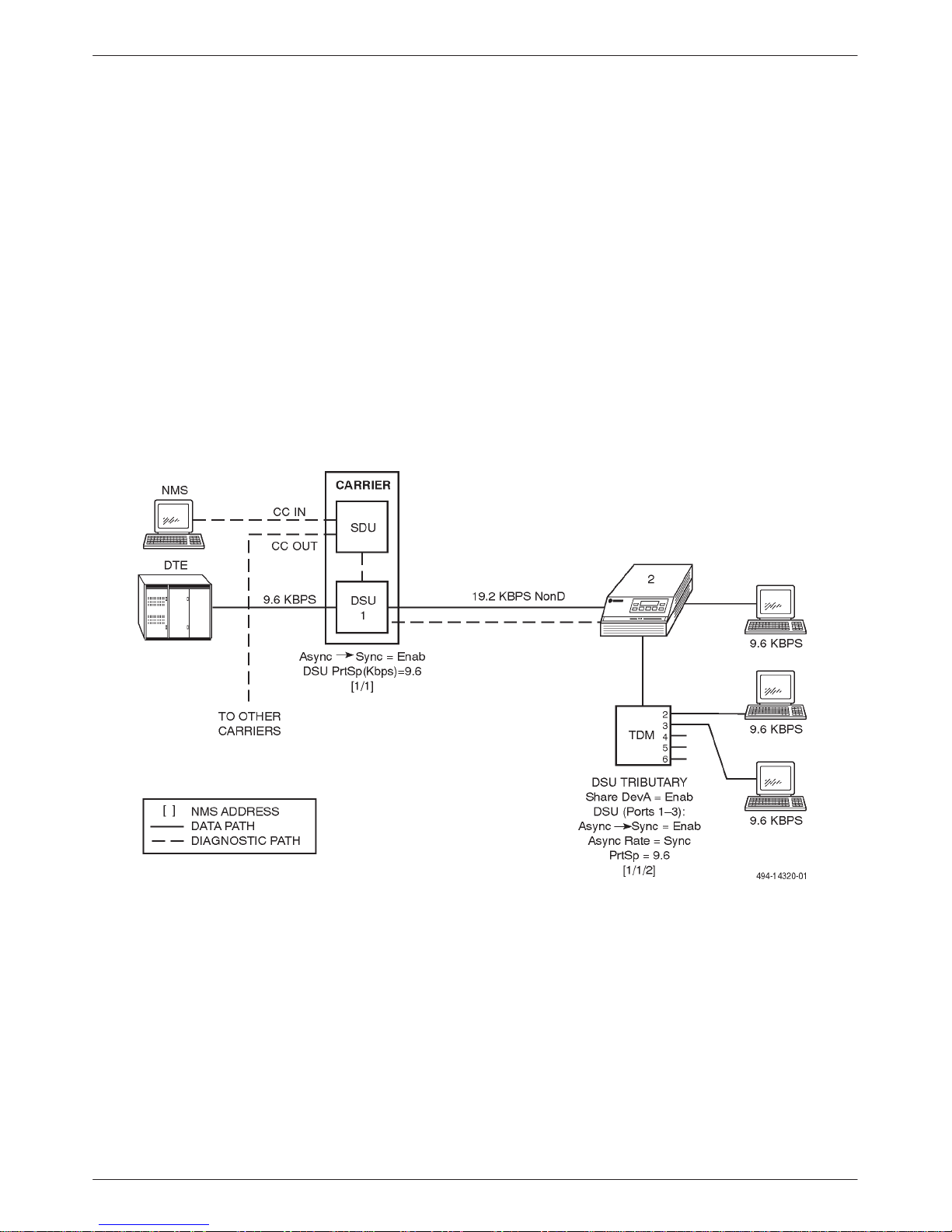
Point-to-Point Configuration
When operating with the Async→Sync configuration
option enabled, a single-port point-to-point circuit can
operate using nondisruptive diagnostics. The control
DSU’s port speed and the tributary DTE port speeds must
be set to the same rate. Figure 1-1 shows this
configuration. Note that the tributary DSUs are configured
as a single port-sharing group.
Figure 1-1. Single-Port Point-to-Point Circuit with Nondisruptive Diagnostics
1-53610-A2-GB91-90 July 1999

COMSPHERE 3600 Series Data Service Units
T able 1-2 specifies the maximum diagnostic rate that
can be run for various asynchronous-to-synchronous
configurations. For example, if the primary channel rate is
56 kbps, the asynchronous DTE rate is 4.8 kbps, and the
synchronous port rate is 48 kbps, then T able 1-2 will show
that the nondiagnostic rate is 2400 bps. In this table, None
indicates that no excess bandwidth is available for
nondisruptive diagnostics. When the DSU is configured
for nondisruptive diagnostics and the Async→Sync
configuration option is enabled, the DTE rate cannot
operate underspeed for diagnostics since the DTE is now
operating in synchronous mode.
Table 1-2
Valid Sync Speeds and Nondisruptive Diagnostics*
DDS
Primary Channel
Rate (kbps)
Async DTE
Rate (bps)
56 56k 56k None
56 48k to 1.2k 48k 2400
38.4 38.4k 38.4k None
38.4 32k to 1.2k 32k 2400
It should be noted that the maximum diagnostic rate
available is 1600 bps, but the DSU’s firmware overrides
any selected rate with a speed up to 2400 bps if more
bandwidth is available for diagnostics.
Asynchronous port speeds of 150, 300, 600, and
1800 bps may be obtained by oversampling; oversampling
must be used to obtain these port rates.
Sync Port
Rate (bps)
Maximum NonD
Rate (bps)
1
19.2 19.2k 19.2k None
19.2 18k 18k 1200
19.2 16.8k to 1.2k 16.8k 2400
9.6 9.6k 9.6k None
9.6 7.2k to 1.2k 7.2k 2400
4.8 4.8k 4.8k None
4.8 4k 4k 800
4.8 2.4k to 1.2k 2.4k 2400
2.4 2.4k 2.4k None
2.4 2k 2k 400
9.6 1.8k 7.2k
2
2400
2.4 1.2k 1.2k 1200
2.4 600 2.4k
2.4 300 1.2k
2.4 150 1.2k
1
These rates are automatically enabled by the firmware, so the NonD speed selected will be overridden
when Oversampling is used. (
2
Oversampling is used.
See the description of NonD in the Diag Type configuration option.
2
2
2
None
1200
1200
)
* This table contains a sample set from which other rates can be derived; it does not include all combinations.
1-6 July 1999 3610-A2-GB91-90
Introduction
The asynchronous word size supported with the
Single-Port Async/Sync feature is 6 to 10 bits, excluding
stop and start bits, for a maximum allowable character
size of 12 bits. In addition, the DSU is V.14 compatible so
the DSU port can run overspeed or underspeed by the
percentage specified by the V.14 requirements. Table 1-3
provides these percentages. For example, if the character
size is 10, the maximum overspeed allowed for the
transmitter is 1.023 times (x) the asynchronous rate.
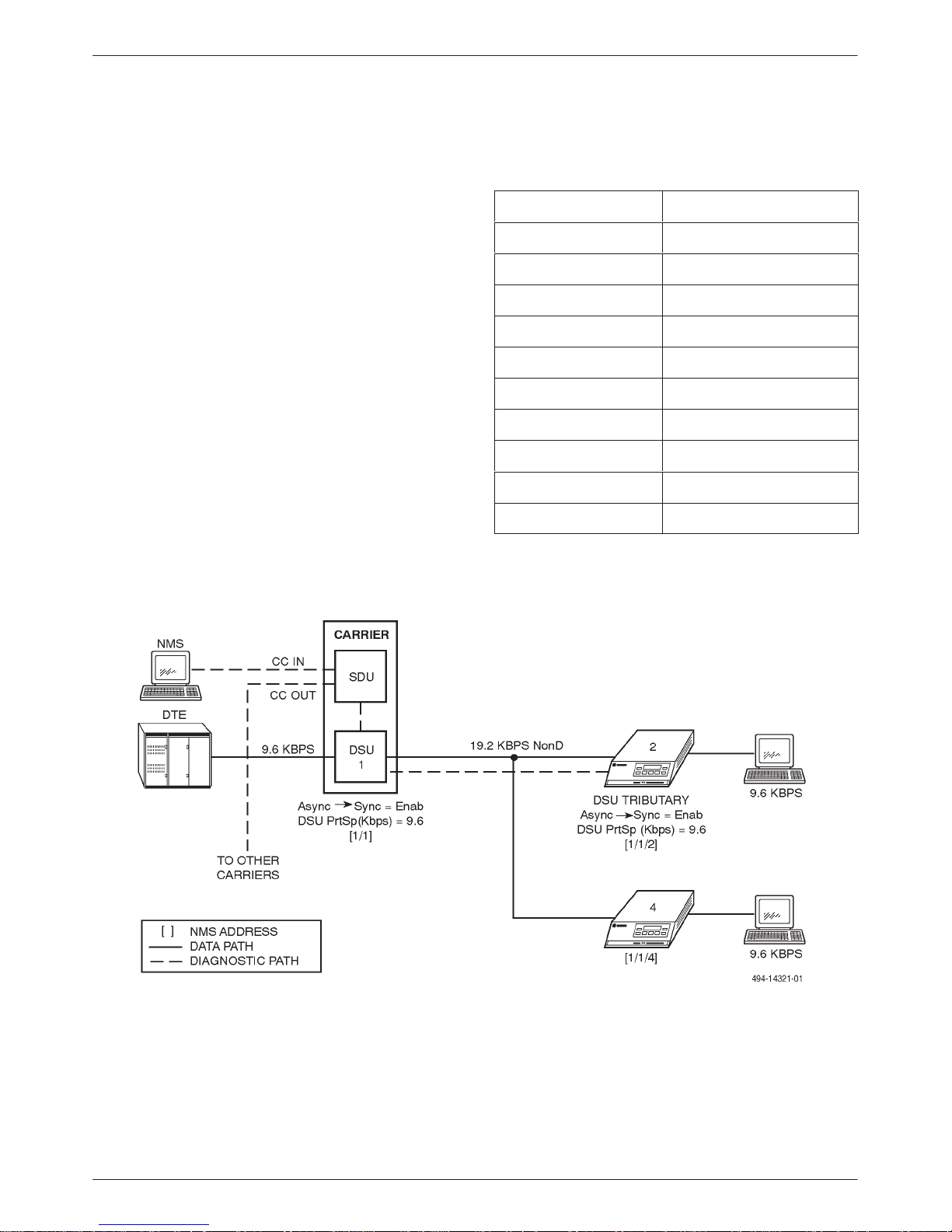
Multipoint Configuration
When operating with the Async→Sync configuration
option enabled, a single-port multipoint circuit can
operate using nondisruptive diagnostics, similar to a
single-port point-to-point configuration. Figure 1-2
illustrates this configuration. Note that both the control
and tributary DSUs have single-port async/sync capability
and are configured the same, with the same rate set for
both the DSU and DTE ports. Refer to Table 1-2 to
determine the maximum diagnostic rate that can be run
for various single-port async/sync configurations, and
T able 1-3 to determine the overspeed or underspeed
percentage at which the DSU port can operate.
Table 1-3
V.14 DTE Overspeed/
Underspeed Percentages
Character Size
8 3.1
8 –2.5
9 2.7
9 –2.5
10 2.3
10 –2.5
11 2.1
11 –2.5
12 2.0
12 –2.5
% Over/Underspeed
Figure 1-2. Single-Port Multipoint Circuit with Nondisruptive Diagnostics
1-73610-A2-GB91-90 July 1999
COMSPHERE 3600 Series Data Service Units
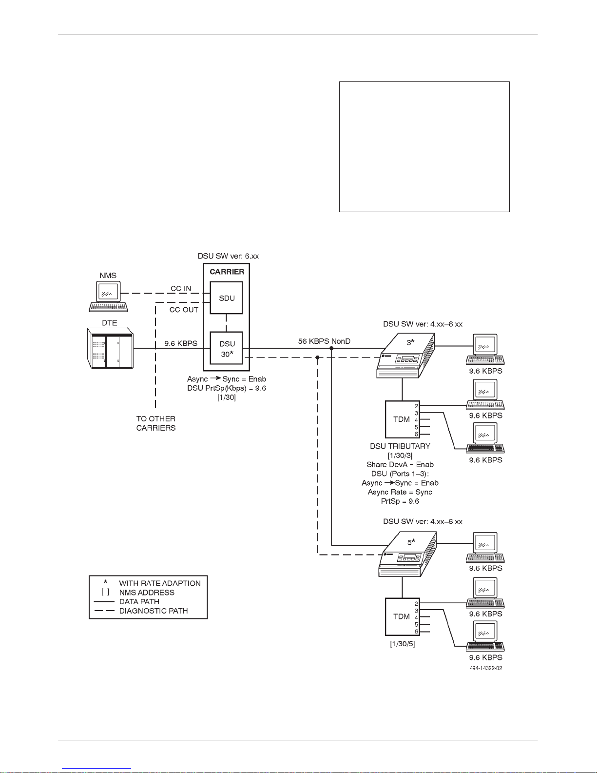
The control DSU with the Single-Port Async/Sync
feature is compatible with earlier DSU releases that use a
TDM with the ports configured as a single port-sharing
group, as long as the control DSU’s port speed and the
port-sharing group port speeds are the same. Earlier DSU
releases from 4.xx to 5.xx can be accommodated as long
as the control DSU’s software/firmware version is 6.xx;
otherwise, the units should be returned to the factory to be
upgraded. (Contact your authorized service representative
to arrange for your upgrade.) Figure 1-3 shows a
compatible configuration. Access the Status (Stat) branch
and select ID (Identity) to determine the DSU’s
software/firmware version (DSU SW ver).
NOTE
For asynchronous ports to
operate at 1200 bps, the
individual asynchronous port
speeds for both the control and
tributary DSUs must be set to
=Sync (Async Rate = Sync) when
the port’s Async-to-Sync
capability is enabled
(Async→Sync = Enab).
Figure 1-3. Multipoint Async-Compatible Network
1-8 July 1999 3610-A2-GB91-90

Introduction
DSU Compatibility
For primary channel communication, the standalone
Model 3610 and the carrier-mounted Model 3611 DSUs
are fully compatible with all Paradyne DSU products.
Point-to-point and multipoint circuits are not limited to
connections between 3600 Series DSUs; many other
combinations of equipment are possible.
The compatibility of the
3600 Series DSUs with the 2500
and 2600 Series devices supports
a smooth transition to an all
3600 Series network.
NOTE
T able 1-4 lists the diagnostic capabilities supported by
a 3600 Series DSU communicating with another device.
In each combination of equipment, the Model 3610 and
3611 DSUs can be either the control or the tributary.
Table 1-4
Diagnostic Compatibilities
Paradyne Device Communicating
with Model 3610/3611 DSU
Diagnostics Supported
3600 Series DSU Enhanced 3600 Disruptive diagnostics (2500, 2600, 3600s,
3600e, Br56), Nondisruptive, NonD, Mixed
3500 Series DSU 2600 diagnostics
2600 Series DSU (DATAPHONEr II)
2600 diagnostics (If there is a control 2600 DSU with a
tributary 3600 DSU, the tributary must be set up as a
2600 DSU in the NMS device profile.)
2500 Series DSU 2500 diagnostics on a point-to-point network; no diagnostics
on a multipoint network (primary channel compatibility only)
3056 DSU No diagnostics (primary channel compatibility only)
3456 DSU No diagnostics (primary channel compatibility only)
1-93610-A2-GB91-90 July 1999

COMSPHERE 3600 Series Data Service Units
Network Management
The 3600 Series DSUs can be managed from both the
diagnostic control panel (DCP) or from an NMS.
Protocols
DMC – Diagnostic MicroComputer is the network
management protocol used by the Paradyne ANALYSIS
6510 Network Management System.
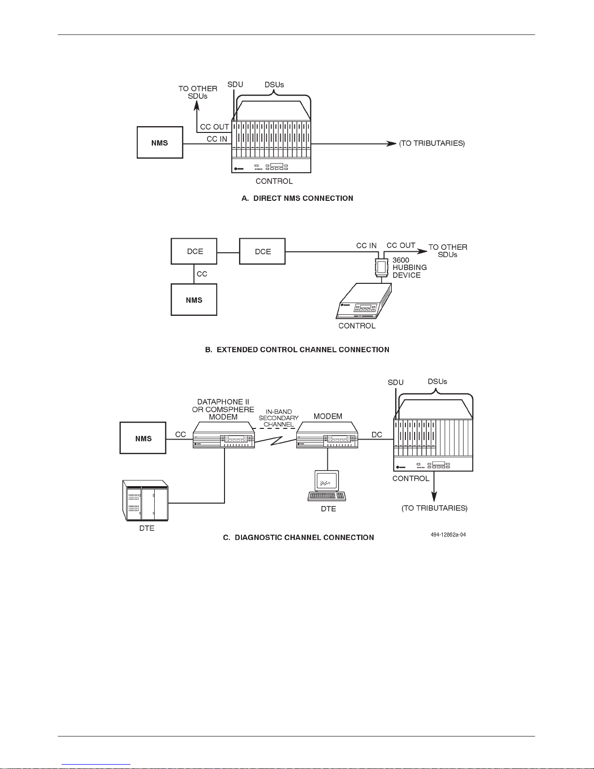
NMS Interface
The DSU provides three channels to carry diagnostic
information, such as Health and Status information and
test reports and results. Figure 1-4 illustrates the various
NMS connections.
The Control Channel (CC) is the connection between
the NMS and a control DSU. It operates at 1200 bps
asynchronous (or 110 bps for DMC).
The 3600 Series DSUs use three protocols to
communicate with the NMS, listed as follows:
• ADp – Advanced Diagnostic protocol is the
network management protocol used by the
COMSPHERE 6700 Series NMS and 6800 Series
NMS.
In-band Secondary Channel T ransport provides
diagnostic communication between a control DSU and a
tributary DSU. The in-band secondary channel transport
can be configured for disruptive, nondisruptive, or mixed
communication. (Refer to the following section, In-Band
Secondary Channel Transport , for further information.)
This feature supports up to 80 addresses for a DPII
protocol or up to 255 addresses for ADp.
The Diagnostic Channel (DC) provides
communication to extended circuits. The Diagnostic
Channel connects the backbone tributary of an extended
circuit to a control DSU (Figure 1-4, Part C). It operates at
1200 bps asynchronous and supports up to 80 addresses
for a DPII protocol or up to 255 addresses for ADp. It is
not supported by a single port multipoint tributary DSU.
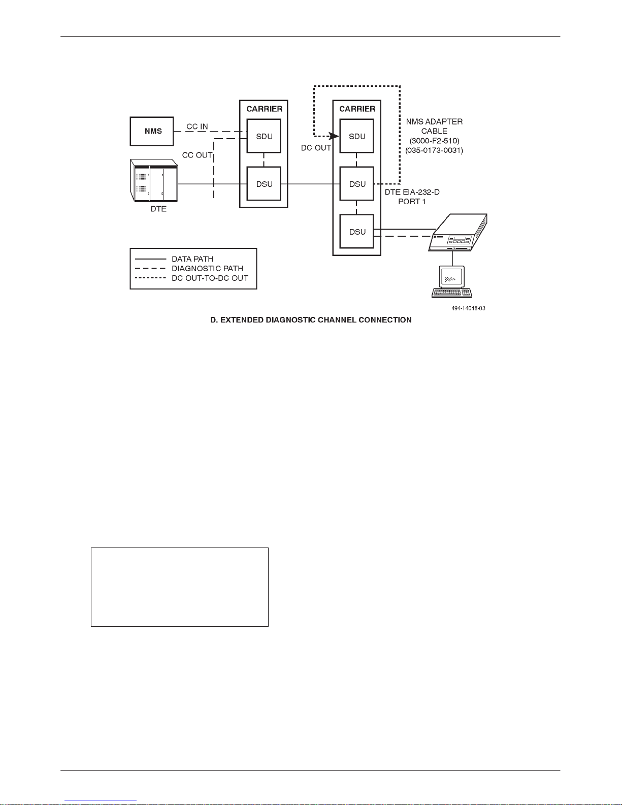
An additional extended diagnostic connection is shown
in Figure 1-4, Part D. In this case, the diagnostic channel
can be extended from a tributary Model 3611 DSU to
another Model 3611 DSU remote location using an NMS
adapter cable (feature number 3000-F2-510). For this
configuration, the remote Model 3611 DSU must be
configured as a tributary. The NMS adapter cable is
connected to Port 1 of the DSU (EIA-232-D); the SDU
must be strapped for a DC connection (S1-2 ON and
S1-1 Off).
• DPII – DATAPHONE II protocol* is the network
NOTE
management protocol used by the DATAPHONE II
family of AT&T NMS products (System Controller,
Diagnostic Console, and Network Controller) or a
COMSPHERE 6800 Series NMS.
For a Model 3611 control DSU,
network management connection
is through the SDU. For a
Model 3610 DSU, a 3600
Hubbing Device is required for
NMS connection.
* When operating in DPII protocol, the diagnostic configurations must follow DATAPHONE II rules (e.g., no
multipoint circuits can be extended off another multipoint circuit; a G2 tributary can have only one device on its poll list.
1-10 July 1999 3610-A2-GB91-90
Introduction
Figure 1-4. NMS Interfaces to the SDU (1 of 2)
1-113610-A2-GB91-90 July 1999
COMSPHERE 3600 Series Data Service Units
Figure 1-4. NMS Interfaces to the SDU (2 of 2)
In-band Secondary Channel Transport
Based upon your entry for the Diag Type (Diagnostic
T ype) configuration option within the Diag (Diagnostic)
option set, one of three methods used for in-band
secondary channel transport may be selected:
nondisruptive diagnostics, disruptive diagnostics, and
mixed diagnostics. The following paragraphs describe
each of these methods. Refer to Tables 6-2, 6-3, and 6-4,
Diagnostic Configuration Options (DSU, DBM, and
General), in Chapter 6 for a description of the
configuration option.
NOTE
Even though the DSU is
configured for nondisruptive
diagnostics, it will also accept
disruptive commands.
Nondisruptive Diagnostics
In a nondisruptive diagnostic network, diagnostic data
is transmitted without interrupting user-transmitted data.
In addition, nondisruptive diagnostics allow the control
DSU to obtain real-time health and status data from its
tributary DSUs and extended circuits. This type of
network is provided through an in-band secondary
channel transport capability. The in-band secondary
channel transport carries diagnostic data while the
user-transmitted data is sent over the primary channel
without interruption.
Three nondisruptive diagnostic techniques are used by
the 3600 Series DSUs. The technique used is dependent
upon whether the circuit is configured for point-to-point,
multipoint, or multichannel multipoint (MCMP). The
technique selected is determined by your LinkConfig
(Link Configuration) selection under the Diagnostic
General option set and MUX Setup configuration options
(Tables 6-4 and 6-9 through 6-11 in Chapter 6 of this
guide).
1-12 July 1999 3610-A2-GB91-90

Introduction
• Point-to-Point Circuit
With this technique, the control DSU uses a Time
Division Multiplexing (TDM) method to allocate a
portion of the total bandwidth for the in-band
secondary channel transport. It can be used for
point-to-point circuits in both single port and TDM
configurations.
You must specify the DDS network line speed and
the DTE port speed. Note that if there is no excess
bandwidth, you must specify the in-band secondary
channel transport speed. In this case, the DSU
reduces the data clock based upon your selection.
T o specify the in-band secondary channel transport
speed, use the configuration option 2nd Ch(bps)
(In-band Secondary Channel Transport Speed) as
shown in T ables 6-6 and 6-7, Diagnostic DSU and
DBM Configuration Options, respectively, in
Chapter 6 of this guide.
• Multipoint Circuit
A multipoint circuit uses two different techniques
for diagnostic transport: one for upstream and one
for downstream.
For downstream diagnostics, the DSU uses a TDM
method to allocate a portion of the total bandwidth
for the in-band secondary channel transport. You
must specify the DDS network line speed and the
DTE port speed. Note that if there is no excess
bandwidth, you must specify the in-band secondary
channel transport speed. In this case, the DSU
reduces the data clock based on your entry. To
specify the in-band secondary channel transport
speed, use the configuration option 2nd Ch(bps)
(Tables 6-6 and 6-7, Diagnostic DSU and DBM
Configuration Options, respectively).
NOTE
In DPII protocol, the Tributary
Time-out alarm is mapped into
the NoResponse alarm.
For upstream diagnostics, the DSU relies on the
primary channel protocol. The tributary DTEs in a
multipoint network are sequentially polled by the
control DTE, and each tributary responds one at a
time with data.
When a tributary DTE raises RTS, no other DTE
should be transmitting. The tributary DSU sends a
few bytes of diagnostic data upstream before
raising CTS to the tributary DTE. Once this is done,
the tributary DSU transmits primary data upstream.
The control DSU maintains a timer for each
tributary DSU. If a tributary DSU does not provide
a health and status update before the timer expires,
the control DSU reports a Tributary Time-out
alarm for the tributary. The duration for the timer is
set using the configuration option TribTimOut
(refer to Table 6-8, Diagnostic General
Configuration Options). The Tributary Time-out
alarm can be triggered by a Facility Alarm, a DSU
Alarm, or a remote DTE Alarm (DTE does not
respond to polls).
Using this technique for a multipoint circuit causes
the downstream data rate to be lower than the
upstream data rate. If this is not acceptable, enable
the configuration option M-PtSymPrt (Multipoint
Symmetrical Port) for all controls and tributaries so
that the upstream and downstream data rates match.
(Refer to T able 6-8, Diagnostic General
Configuration Options, in Chapter 6 for further
information.)
• Multichannel Multipoint (MCMP)
For MCMP nondisruptive diagnostics, built-in
in-band secondary channel transport is provided;
you do not need to reduce the bandwidth. The Diag
T ype (Diagnostic Type) configuration option should
be set to NonD.
NOTE
Diagnostic types and in-band
secondary channel transport
speeds must be set to the same
value for both the control and the
tributary DSUs. If these
configuration options are set to
different values and
communication to the tributary is
lost, reconfigure the control for
disruptive diagnostics and
reconfigure the tributary, as
required.
1-133610-A2-GB91-90 July 1999

COMSPHERE 3600 Series Data Service Units
Disruptive Diagnostics
In a disruptive diagnostic network, the same channel
(that is the primary channel) that carries user-transmitted
data between the control and tributary DSUs also carries
diagnostic data. Since diagnostic data is transmitted on the
primary channel, this may interrupt user-transmitted data
and cause errors in transmission. Retransmission of data
blocks may be required. (Most diagnostic disruptions are
less than 0.5 seconds in duration and should not cause loss
of the communication session.)
If there is a dialed connection between the control and
tributary via the DBMs and the customer data is still
routed on the DDS link, the standby facility (Standby
mode) provides a nondisruptive channel for diagnostic
traffic.
A tributary, whether a standalone or carrier-mounted
model, can receive disruptive tests and commands from its
local DCP as well as from the control for point-to-point
circuits. Local health and status commands are
nondisruptive. Commands directed to a tributary DSU
from the NMS or a control DSU’s DCP may cause data
errors requiring retransmission of the data.
Mixed Diagnostics
This method is used primarily for multipoint
configurations, with the advantage that it uses a standard
non-reduced data clock while still providing nondisruptive
health and status updates. It supports a combination of
nondisruptive and disruptive techniques. Health and status
information is sent nondisruptively (using the upstream
technique described for the Multipoint Circuit), while
user-initiated commands and tests are sent disruptively. To
use Mixed diagnostics in a point-to-point configuration,
you must configure the DSUs for multipoint operation
using the LinkConfig (Link Configuration) configuration
option as described in T able 6-4, Diagnostic General
Configuration Options, in Chapter 6.
the SDCP and it consists of the carrier number and slot
number.
The ADp control network address is used by the NMS
to access the DSU. A control network address is any
number in the range from 1 through 255 with the
following exceptions:
• The number 192 is reserved as a broadcast address
and must not be assigned as a network control
address.
• The numbers 191 and 255 may not be assigned to
any DSU with an attached DBM. (The DBM
address is always the DSU’s network address
plus 1.)
This range of addresses is valid for any position the
DSU occupies in the network (control, tributary, extended
control, extended tributary).
NOTE
When using DPII protocol, a
tributary DSU must have an
address in the range of 1 through
80. (Address 80 cannot be
assigned to a DSU with an
attached DBM.)
The control network address is protocol-dependent, as
explained in the Control Network Address section that
follows.
You must assign a unique network address for each of
the following:
• Each control DSU on the same control channel.
• Each extended control DSU attached to a single
tributary.
• Each tributary in a multipoint circuit.
Addressing
A Model 3611 DSU has two addresses:
• Physical address
• Control network address (user-definable)
The physical address is determined by the location of
the DSU in the COMSPHERE 3000 Series Carrier cabinet
configuration. It is only used for commands issued from
1-14 July 1999 3610-A2-GB91-90
A tributary DSU also has a network address, which
follows the same addressing scheme as the control
network address.
An NMS can access a tributary DSU by first
addressing the control DSU and then addressing the
tributary DSU from the control. An address issued by the
NMS is defined as control channel/control network
address/tributary network addr ess (e.g., 1/157/1). This
type of addressing is called link-level network addressing.
 Loading...