

Page 1

COMSPHERE
3600 SERIES
DATA SERVICE UNITS
TIME DIVISION MUL T IPLEXER,
MULTICHANNEL MULTIPOINT,
AND DIGITAL BRIDGE OPTIONS
QUICK REFERENCE
Document No. 3610-A2-GL12-00
Page 2

Copyright 1998 Paradyne Corporation.
All rights reserved.
Printed in U.S.A.
Notice
This publication is protected by federal copyright law. No part of this publication may be
copied or distributed, transmitted, transcribed, stored in a retrieval system, or translated
into any human or computer language in any form or by any means, electronic,
mechanical, magnetic, manual or otherwise, or disclosed to third parties without the
express written permission of Paradyne Corporation, 8545 126th Ave. N., Largo,
FL 33773.
Paradyne Corporation makes no representation or warranties with respect to the
contents hereof and specifically disclaims any implied warranties of merchantability or
fitness for a particular purpose. Further, Paradyne Corporation reserves the right to
revise this publication and to make changes from time to time in the contents hereof
without obligation of Paradyne Corporation to notify any person of such revision or
changes.
Changes and enhancements to the product and to the information herein will be
documented and issued as a new release to this manual.
Warranty, Sales, and Service Information
Contact your local sales representative, service representative, or distributor directly for
any help needed. For additional information concerning warranty, sales, service, repair,
installation, documentation, training, distributor locations, or Paradyne worldwide office
locations, use one of the following methods:
Via the Internet: Visit the Paradyne World Wide Web site at
http://www.paradyne.com
Via Telephone: Call our automated call system to receive current information via
fax or to speak with a company representative.
— Within the U.S.A., call 1-800-870-2221
— Outside the U.S.A, call 1-727-530-2340
Document Feedback
We welcome your comments and suggestions about this document. Please mail them
to Technical Publications, Paradyne Corporation, 8545 126th Ave. N., Largo, FL 33773,
or send e-mail to userdoc@eng.paradyne.com. Include the number and title of this
document in your correspondence. Please include your name and phone number if you
are willing to provide additional clarification.
Trademarks
All products and services mentioned herein are the trademarks, service marks,
registered trademarks or registered service marks of their respective owners.
Page 3

TM
1
COMSPHERE 3600 Series Data Service Units
Time Division Multiplexer, Multichannel Multipoint,
and Digital Bridge Options
Quick Reference
Document Number 3610-A2-GL12-00
November 1998
Product Documentation on the World Wide Web
We provide complete product documentation at www.paradyne.com. This lets you
search the documentation for specific topics and print only what you need, reducing the
waste of surplus printing. It also helps us maintain competitive prices for our products.
Select
Service & Support → Technical Manuals → Subrate Digital Access Devices
.
Then select the following documents:
3610-A2-GB46
COMSPHERE 3600 Series Data Service Units,
Models 3610 and 3611, User’s Guide
3610-A2-GB48
COMSPHERE 3600 Series Data Service Units,
Models 3610 and 3611 Time Division Multiplexer, Multichannel Multipoint, and
Digital Bridge Options, Supplement
To request a paper copy of a Paradyne document:
Within the U.S.A., call 1-800-PARADYNE (1-800-727-2396)
Outside the U.S.A., call 1-727-530-8623
Things to Know Before Installation
The COMSPHERE Model 3610 DSU with the TDM or MCMP option is delivered with
default hardware settings, factory default configuration option settings, and
factory-installed software.
Port 1 of the DSU is preconfigured to operate with the TDM or MCMP capability
enabled. The DSU includes the factory default configuration option settings for
FacT with some defaults based on hardware.
For the Model 3610, all additional ports are disabled and preconfigured for EIA-232
port interface operation. Each port configured for V.35 needs an interconnect cable
(Feature Number 3000-F1-510).
Once a DSD model is powered up, you can verify the port interface switch setting
through the right side of the back panel.
— If set for EIA-232, you will see a green light.
— If set for V.35, you will see a yellow light.
Page 4
496-15149
2
Installing the DSU
The Model 3610 DSU is designed for desktop operation.
Place the DSU in the planned location.
Allow 1 to 2 feet of clearance for cable connections, space for the ventilation slots
on the sides, and clearance at the rear for the cable connections.
Hardware Settings
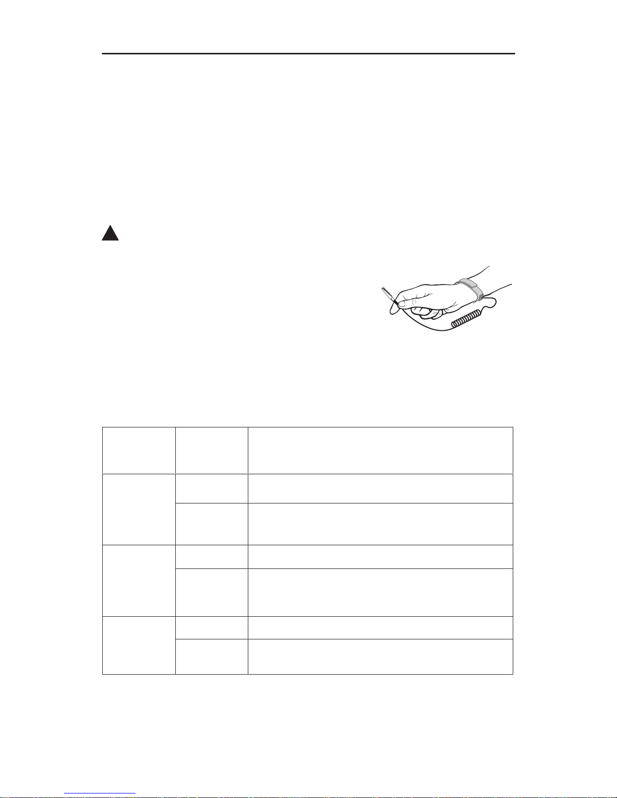
!
HANDLING PRECAUTIONS FOR STA TIC-SENSITIVE DEVICES
This product is designed to protect sensitive components from
damage due to electrostatic discharge (ESD) during normal
operation. When performing installation procedures,
however, take proper static control precautions to
prevent damage to equipment. If you are not sure
of the proper static control precautions, contact
your nearest sales or service representative.
TDM/Flex and MCMP/Flex models are available with two or six ports. When your
firmware version is 6.33 or greater, each port can be set individually for either EIA-232
or V.35 using the front panel, an async terminal, or an NMS.
Based on your model, you may need to perform one of following procedures. Use ID
from the Status branch to obtain the firmware version.
If your
model is a
6-port . . .
And the
EIA-232
setting . . .
Then . . .
TDM/Flex or
MCMP/Flex
Is correct Go to
Powering Up the DSU
, page 9.
MCMP/Flex
with firmware
6.33 or
greater
Needs to be
changed
Go to
Powering Up the DSU
, page 9, and
Reconfiguring Ports
, page 10.
TDM/Flex or
Is correct Go to
Powering Up the DSU
, page 9.
MCMP/Flex
with firmware
less than
6.33
Needs to be
changed
Change the S1 switch setting on the TDM/Flex or
MCMP/Flex circuit card to the On position for V.35 or
Off position for EIA-232.
Is correct Go to
Powering Up the DSU
, page 9.
TDM/DSD or
MCMP/DSD
Needs to be
changed
Change the option card to set all six ports. Start with
the next section,
Opening the DSU
.
Page 5
3
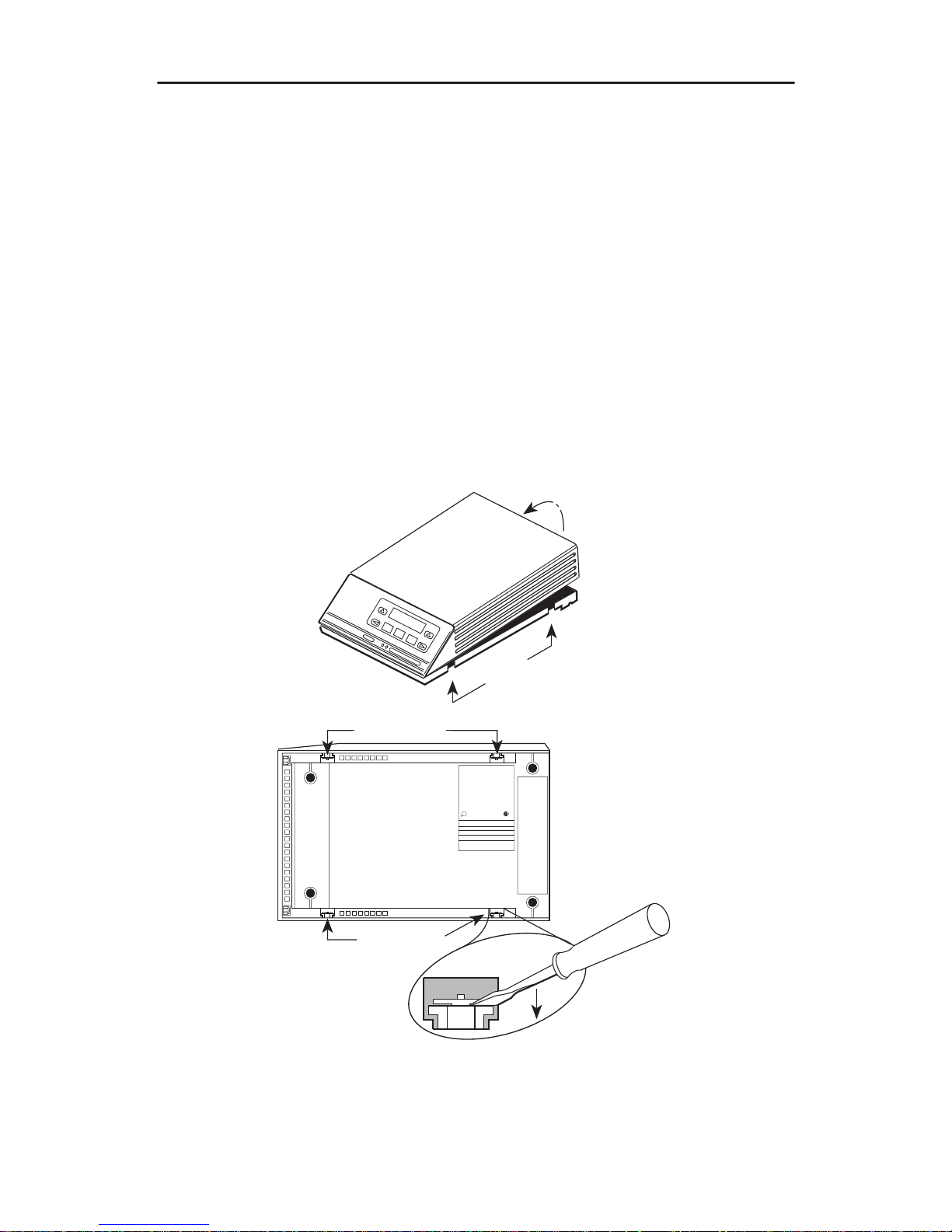
Opening the DSU
NOTE:
If the unit is already installed, disconnect all cables, including the power source,
before opening the DSU.
Opening a Model 3610 DSU without MUX
Follow this procedure to separate the DSU cover from the base.
Procedure
1. Turn the unit upside down and release the four snap tabs using a small flat-blade
screwdriver. Tabs release when you push in and up with the screwdriver.
2. Turn the unit upright and bring the cover toward the front panel. Do not allow any
cables to pull free from the inside front panel connectors.
496-14706-02
Snap Tabs
R
U
L
R
THIS DIGITAL APPARATUS DOES NOT EXCEED THE CLASS A LIMITS FOR RADIO NOISE
EMISSIONS FROM DIGITAL APPARATUS SET OUT IN THE RADIO INTERFERENCE
REGUAALTIONS OF THE CANADIAN DEPARTMENT OF COMMUNICATIONS
FOR USE WITH A CERTIFIED CLASS 2 POWER SUPPLY FOUR UTILISER AVEC LINE
ALIMENTATION CERTIFEE
EN CLASSE 2.
THIS DEVICE COM;OIES WITH PART 15 OF THE FCC RULES OPERATION IS SUBJECT TO
THE FOLLOWING TWO CONDITIONS (1) THIS DEVICE MAY NOT CAUSE HARMFUL
INTERFERENCE AND (2) THIS DEVICE MUST ACCEPT ANY INTERFERENCE RECEIVED
INCLUDING INTERFERENCE THAT MAY CAUSE UNDESIRED OPERATION.
FCC ID: NOT APPLICABLE
PEC
MFG DATE
MODEL
NO.
SER.NO
COMM CODE
MADE IN USA
Snap Tabs
Snap
Tabs
COMSPHERE 3610
Page 6
4
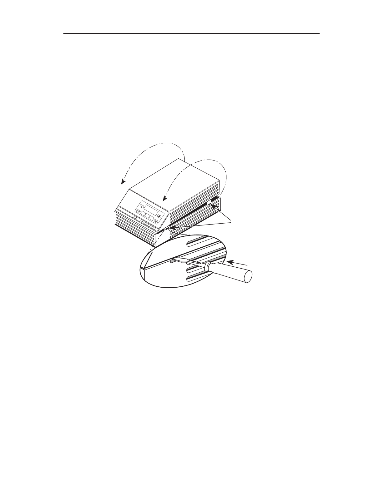
Opening a Model 3610 DSU with MUX
Follow this procedure to separate the MUX DSU cover from the base and to separate
the DSU circuit card from the MUX circuit card.
Procedure
1. Use a small flat-blade screwdriver to release the four snap tabs holding the base in
place. Tabs release when you push in and up with the screwdriver. Remove the
cover toward the front panel. Do not allow any cables to pull free from the inside
front panel connectors.
496-14707-01
With TDM
or MCMP
Snap Tabs
COMSPHERE 3610
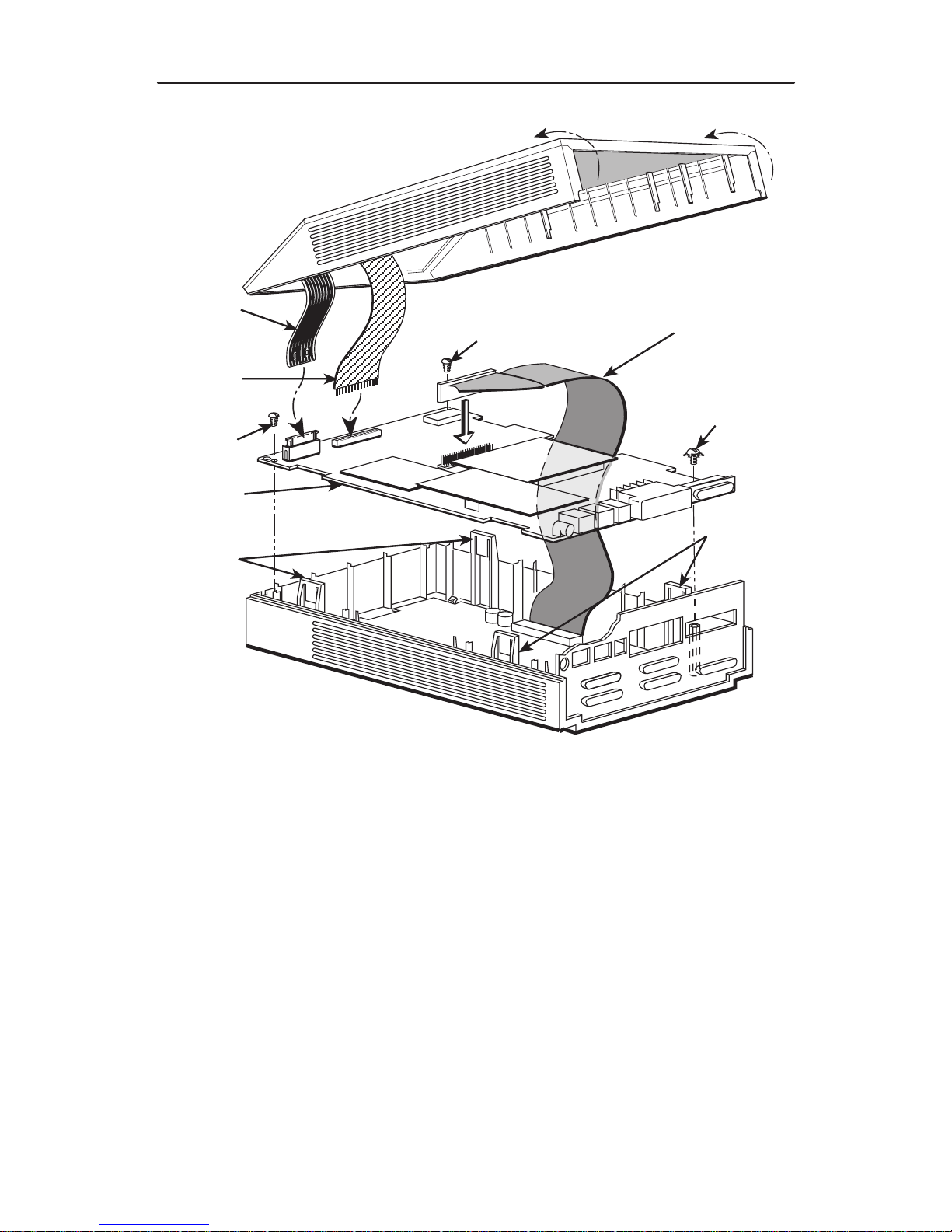
2. Disconnect the LCD flat cable by working the cable free of the connector.
3. Disconnect the keypad flat cable from the DSU circuit card by
squeezing the
latches
on each side of the cable connection and pulling up on the keypad flat
cable.
4. Disconnect the TDM/MCMP flat cable.
5. Unscrew the three screws holding the DSU circuit card in place.
6. Lift the DSU circuit card from the base and set aside.
Page 7
5
LCD
Flat
Cable
Keypad
Flat
Cable
DSU
Circuit
Card
Expanded
Base
Snap
Tabs
TDM or MCMP
Flat Cable
Screw
98-13846d
Snap
Tabs
Screw
Screw
Assembling and Disassembling a TDM or MCMP DSU
Page 8
6
Changing the EIA-232 or V.35 Interface
Follow this section to change a TDM/DSD or MCMP/DSD model from:
H EIA-232 interface to V.35 interface, or
H V.35 interface to EIA-232 interface
Separating the DSU from the TDM or MCMP
Follow this procedure to separate the DSU circuit card from the TDM or MCMP.
" Procedure
1. Disconnect the keypad flat cable from the DSU circuit card by squeezing the
latches
on each side of the cable connection and pulling up on the keypad flat
cable.
2. Disconnect the LCD flat cable by working the cable free of the connector.
3. Disconnect the TDM or MCMP flat cable.
4. Unscrew the three screws holding the DSU circuit card in place.
5. Lift the DSU circuit card from the base and set aside.
Changing the DSD Option Card Setting
For the TDM/DSD or MCMP/DSD model, use the following procedure to change the
setting from EIA-232 to V.35 or from V.35 to EIA-232.
" Procedure
1. Work the option card free of its connector.
Option
Card
Rear
Panel
LED 2
(Yellow
V.35)
LED 1
(Green
EIA-232)
496-13845-03
THIS SIDE FACES REAR FOR V.35
S1
S2
2. Turn the card around and re-insert. In the example above, the card reads THIS
SIDE FACES REAR FOR V.35.
Page 9
7
Adding the MCMP/TDM Flex Option to a
Model 3610 DSU
An MCMP/TDM circuit card assembly (CCA) can be added to an installed DSU. The
MUX CCA must be physically and electrically connected to the DSU. The Model 3610 is
installed into a larger base.
The MCMP/TDM Flex model is designed so that each port can be set individually to
either EIA-232 or V.35 by using either the front panel, an async terminal, or an NMS.
The firmware version must be 6.33 or greater.
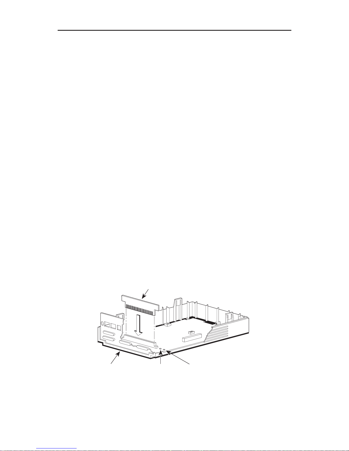
Adding a MUX CCA
To upgrade a 3610 DSU with a MUX CCA:
Procedure
1. Fold the TDM/Flex or TDM/Flex flat cable over the side of the new expanded base.
2. Position the DSU over the expanded base.
3. Proceed to
Reassembling the DSU
on page 8.
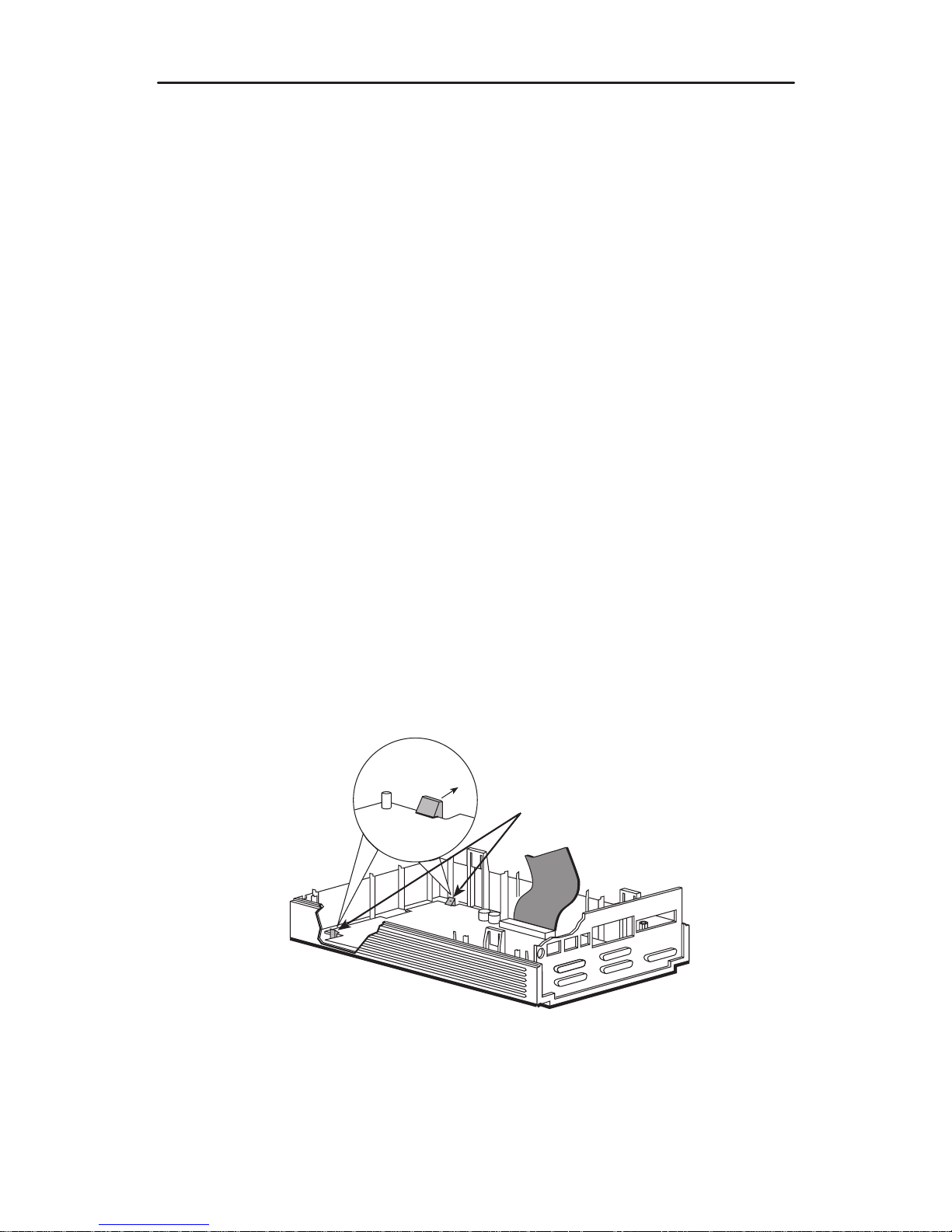
Replacing an Installed MUX CCA
To replace an existing MUX CCA:
Procedure
1. Release the two snaplocks holding the MUX CCA in the base. Remove the MUX
CCA.
Snaplocks
496-15229
TDM/MCMP
Flat Cable
2. Place the new CCA into the two snaplocks in the base.
Page 10

8
3. Connect the 40-pin TDM/MCMP flat cable to the new MUX CCA. Fold the flat cable
out over the side of the new expanded base.
4. Proceed to
Reassembling the DSU
.
40-Pin
TDM/MCMP
Flat Cable
496-15230
Snap
Tabs
Reassembling the DSU
Procedure
1. Secure the DSU to the expanded base using the two #4 thread-cutting screws at
the front corners, and the #4 screw with the captive lock-washer at the back corner.
2. Connect the flat cable’s 40-position header to the DSU as shown on page 5.
3. Connect the keypad flat cable by inserting the cable into its connector as far as it
will go, then pushing down on the latching mechanism.
4. Being careful not to bend the pins, align the LCD flat cable with its connector. Push
the cable into place.
5. Align the rear panel and four snap tabs. Replace the cover over the expanded
base, allowing the four tabs to snap into place.
Page 11

9
Powering Up the DSU
CAUTION:
The power cord contains a 3-wire grounding-type plug which has a
grounding pin. This is a safety feature. Grounding of the unit is vital to ensure
safe operation. Do not defeat the purpose of the grounding plug by modifying
it or by using an adapter. Prior to installation, use an outlet tester or voltmeter
to check the ac receptacle for earth ground. If the power source does not
provide a ground connection, consult an electrician to determine another
method of grounding the unit before proceeding with the installation.
" Procedure
1. At the rear of the DSU, insert the small end of the power cable into the receptacle
labeled POWER.
495-14710
PORT 5 PORT 3
PORT 6 PORT 4 PORT 2
POWER
LINE
BACKUP
CC/DC
EIA 232
V.35
CAUTION:
Only use the power transformer designed for the Model 3610 DSU. Using
other transformers may result in personal injury or damage to the equipment.
2. Connect the 3-prong plug at the other end of the cable to an ac outlet.
Power-Up Routine
When you apply power the first time, the DSU performs a power-up routine and:
H Determines what hardware options are installed. This may include MUX to
represent TDM or MCMP.
H Automatically runs a Device Test on the DSU and each installed hardware option.
All front panel lights flash on and off.
H If a TDM or MCMP is installed, MUX appears as Pass or Fail on the LCD.
Refer to your User’s Guide for power-up messages and steps for saving and changing
configuration options.
If a Fail message appears or an installed hardware option does not appear, refer to
Document No. 3610-A2-GB46 for DSU troubleshooting and Document No.
3610-A2-GB49 for DBM troubleshooting.
Page 12

10
DTE Connections
Make the DTE connections as described in the User’s Guide.
In a TDM or MCMP application, all ports default to EIA-232 port interface operation. For
MCMP/TDM Flex, Ports 1 through 6 can be set individually to EIA-232 or V.35 by using
the MUX port configuration options.
For an EIA-232 connection with distances greater than 50 feet or data rates higher than
19.2 kbps, use short, high quality cable with low capacitance and a DTE capable of
supporting the distance and data rate.
When Port 1 requires a speed higher than 19.2 kbps, it is recommended that the port
interface be set to V.35. An interconnect cable is required for every port (2 through 6)
that is set to V.35 interface.
Reconfiguring Ports
If you have a MCMP/TDM Flex with a firmware version 6.33 or greater, you can
configure each port for either EIA-232 or V.35 interface compatibility from the front
panel, an async terminal, or an NMS.
To set a port for EIA-232 or V.35 operation:
Procedure
1. From the Home screen, select Local (F1). The following screen appears on the
LCD.
F1
Local Mode:
Stat Bckup Test
F2
F3
Confg Ctrl
2. Press the key until Confg appears.
3. Select Confg (Configuration branch). The Configure screen appears.
4. Select Opts. The Load from screen appears.
Page 13

11
5. Select Activ (F1). The Edit/Save screen appears.
F1
Edit/Save:
SAVE DSU Diag
F2
F3
DBM Gen Bkup MUX PrtSp
LPDA
6. Press the or key to scroll the MUX option set into view.
7. Press the function key directly below MUX. The Change MUX Opts screen
appears.
F1
Change MUX Opts:
Copy Setup Prt1
F2
F3
Prt2 Prt3 Prt4 Prt5 Prt6
8. Select a port:
— Any of the installed ports, Prt1 through Prt6, for a 6-port MCMP/TDM Flex
— Prt1 or Prt2 for a 2-port MCMP/TDM Flex
9. Press Next or Prev and select EIA232 or V.35.
F1
DTE Port: EIA232
Next EIA232 V.35
F2
F3
Prev
Page 14

12
If you are . . .
Then return to . . .
Selecting another port Change MUX Opts, Step 7.
Finished The Edit/Save screen.
10. Select SAVE.
Network Verification Testing
Perform verification testing after any installation.
" Procedure
1. Request a device Identity report from each tributary to ensure that the DSU is
addressed properly (ID from the Status branch).
NOTE:
The Model 3610 is delivered with its network address set to 254.
2. Perform a Digital Test on the DDS circuit to ensure that the network is functioning
(DT from the Test branch).
Perform a Digital Test on each:
— Active port when MUX Funct is set to TDM
— Tributary DSU when MUX Funct is set to MCMP
NOTE:
A
control DSU
can originate a Digital Test in a point-to-point or multipoint
network. Use Position in the Diagnostic General configuration option table to
set a unit to Cntrl.
A
tributary DSU
can originate a Digital Test in a point-to-point network only,
provided the configuration option Respond to Remote Digital Loopback
(RespondRDL) is enabled in the control.
Front Panels
The front panel is the user interface to the DSU. There are two types of front panels:
H Front panel on the Model 3610 DSU.
H SDCP (shared diagnostic control panel) used with the Model 3611 DSU in a
COMSPHERE 3000 Series Carrier.
Front panel operation does not vary with the addition of DSU options (DBM, TDM,
MCMP, or SNA Diagnostic Interface). However, menu or selection displays may vary
based on installed options. Refer to the User’s Guide for basic front panel, display,
keypad, and menu function information.
Page 15

13
Menu Structure
A 3600 Series DSU comes factory-loaded with default configuration settings:
Model 3610 DSU is configured as a tributary (FacT)
Model 3611 DSU is configured as a control (FacC)
DSU with MCMP/TDM comes configured as a TDM
Menus and Modes of Operation
A DSU without TDM or MCMP operates in Basic mode. A DSU equipped with TDM or
MCMP can operate in one of several modes. The mode of operation affects which
menus appear and the selections available within the menus. Use the MUX Function
configuration option to set the mode of operation.
Access to all network management tasks from the front panel begins at the top-level
menu, the head of the menu hierarchy. Press the
key from anywhere in the menu
to return to the top-level menu.
495-12970b
TOP-LEVEL MENU
Local
Remot
Bckup
Test
Ctrl
Msgs
Address
Confg
Stat
Local/Remote Branch Menus
The Local branch menu has five branches; the Remote branch has four (Bckup is not
available):
Status (Stat) branch
Backup (Bckup) branch
Test branch
Configuration (Confg) branch
Control (Ctrl) branch
Page 16

14
Status Branch
The Status (Stat) branch includes reports on the health and status of the DSU, TDM,
MCMP, and DBM.
496-12970-02
TOP-LEVEL MENU
Local
Remot
Bckup
Test
Ctrl
Msgs
Address
Confg
Stat
H/S DTE CircQ ID TPwr
Port
Select
Devic Expan Subn
Backup Branch
The Backup (Bckup) branch controls operation of digital bridging when a DSU with
TDM or MCMP has MUX Funct set to CBrdg or EBrdg.
496-12971-06
TOP-LEVEL MENU
Local
Remot
Test
Ctrl
Stat
Msgs
Address
Confg
Bckup
Abort Bkup Dial DrBU Disc →Dial →DDS AggSw →NetI
Page 17

15
Test Branch
The Test branch provides extensive testing capabilities for the DSU, DDS circuit, DBM,
and backup circuit.
496-12972-03
TOP-LEVEL MENU
Local
Remot
Bckup Ctrl
Stat
Msgs
Address
Confg
Test
DSU DBM
Abort Devic Lpbk Lamp
LL DTE DL RL
Start Start Start
Port
Select
Port
Select
Port
Select
Port
Select
Address
Address Address
Run
Tim
# Blocks
Displ Clr
EE DT
BERT
Port
Select
Subn Selective
DTone
Configuration Branch
The Configuration (Confg) branch allows you to configure or customize the DSU and its
options.
The Configuration branch menu varies with the options being configured. With TDM or
MCMP installed, the MUX and PrtSp (Port Speed) option sets appear.
Page 18

16
498-12973-08
TOP-LEVEL MENU
Local
Remot
Bckup
Test
Ctrl
Stat
Confg
Msgs
Opts PList Dir Phone
Addr
ChgMd
Displ Chang
Add
Acq
Activ
Delet
Chang Clr
Save
DPII
ADp
Remt
Address
Activ Usr1 Usr2 Usr3
Activ
Usr1
Usr2
Usr3
FacC
FacT
FacB
Load
SAVE DSU DBM Gen Bkup MUX
PrtSp
LPDA
Copy
Setup Prt1 Prt2 Prt3 Prt4 Prt5 Prt6
Remt Usr1 Usr2 Usr3
Address
Activ Usr1 Usr2 Usr3
TDM MCMP CBrdg EBrdg None
DSU DBM Chan
Skip
Clr
Diag
All Prt1 Prt2 Prt3 Prt4 Prt5 Prt6
Copy
To
Activ
Address
DSU DBM Gen
Prt1 Prt2 Prt3 Prt4 Prt5 Prt6
Copy
From
Term
Enab Pswrd CIDDisab
Pswrd
SPID
Menu
FB1
Chang Clr
Save
Enab
Disab
MPTC
MPTT
Page 19

17
Configuration Option Tables
In the tables that follow, FacT (Factory Tributary) defaults are shown in boldface. If
different from the FacT defaults, FacC (Factory Control) defaults are shown in
italics
.
Key to symbols:
A
Configuration options that do not appear when Full mode is disabled using
Menu from the Configuration branch.
H
ISDN and Switched 56 Digital DBMs
L
ISDN DBM only
LL
V.32 Analog DBM only
F
When the Async→Sync configuration option is enabled using the MUX Port
n
branch, the following DBM PrtSp settings do not appear: 32, 18.0, 8.4, 4.0,
and 2.0 kbps.
FF
19.2 Power Level defaults to +6 dB when ID App Module displays XLOOP
FF F
ISDN and 2-wire Switched 56 DBMs only
}
Not available for Switched 56 DBMs; defaults to 56 kbps.
}}
Ports 3–6 are not available for 2-port Flex MUX models.
z
Not available for a DBM-X or a DSU with Primary core set to Yes; the DSU is
Disabled
zz
4-wire Switched 56 DBM only
:
Appears with MCMP/TDM Flex with DSU firmware version 6.33 or greater.
::
Appears when non-Flex MCMP/TDM is installed or 6-port MCMP/TDM Flex is
installed with firmware version less than 6.33
DSU Configuration Options
DSU
Configuration Options
Value
Rate(Kbps) Auto, 64CC, 64L, 56, 38.4, 19.2, 9.6, 4.8, 2.4
TxClkSource Int, RXC, Ext, DDS, Prt1, Prt2, Prt3, Prt4, Prt5, Prt6
Msg Clamp A Enab, Disab
TxElasStor Enab, Disab
RxElasStor A Enab, Disab
19.2 PowrLvl DD A
+6, 0, –10
64KScramblng A On, Off
64KLatchLpbk A On, Off
NetIntf A AggSw, Forc, Disab
Net ITiming A Int, NetI, Prt1, Prt2, Prt3, Prt4, Prt5, Prt6
V.54 Lpbk A Enab, Disab
Diagnostic DSU
Configuration Options
Value
Diag Type NonD, Disr, Mixed, None
2nd Ch(bps) A 100, 400, 800, 1200, 1600
Disr Type 2500, 2600, 3600s, 3600e, Br56
Page 20

18
Diagnostic General
Configuration
Options
Value
Position
Cntrl
, Trib, G2Trb
LinkConfg Pt-Pt, M-Pt
Resp Period A 1, 2, 10
TribTimOut A 0:10 (5 sec to 10 min)
Diag Conn CC, DC
Link Delay A 0s, 1s, 2s, 5s, 10s, 20s, 50s
Network Delay A 0s, 1s, 2s, 5s, 10s, 20s, 50s
Packet Delay A 0s, 1s, 2s, 5s
Fast Sel A Enab, Disab
General
Configuration Options
Value
DTE Port :: EIA232, V.35
RTS Cntrl
FrcOn
, DTE
CTS Cntrl Std, =RTS
LSD Lead A Std, Delay, FrcOn
CTS Lead A Std, Delay, FrcOn
SystemStat A Enab, Disab
Circ Assur A Enab, Disab
Tst Pattern A AT&T, Std
RespondRDL A Enab,
Disab
LL by DTE A Enab, Disab
RL by DTE A Enab, Disab
Bilat Lpbk A Enab, Disab
Ext Leads A ExtLd, Rate, RPowr
CCN by EL A Enab, Disab
SW Vers A 3.24, 4.43, 6.66, Normal
AnswExtBU A Enab, Disab
RLSD in MCMP H A Yes, No
PowerOnTst Enab, Disab
LPDA-2
Configuration Options
Value
LPDA-2 Enab, Disab
LPDA Address 1–256
SNA Backup Enab, Disab
Code 1 582210 (6 digits)
Code 2 5822101 (7 digits)
Page 21

19
ChgMd
Configuration Options
Value
Protocol Mode DPII, ADp
DBM Configuration Options
DBM
Configuration Options
Value
Rate(Kbps) } 56, 28.8, 24.0, 19.2, 16.8, 14.4, 12.0, 9.6, 7.2, 4.8, 2.4
TxClkSourceLL}}
Int
, RXC, DSU, Prt1, Prt2, Prt3, Prt4, Prt5, Prt6
CarrLossDisc LL A Yes, No
Auto Retrain LL A Yes, No
Single Rate LL Yes, No
Fallback L None, All, One (All without TDM, One with TDM)
AutoAnswer A Enab, Disab
TxElasStor Enab, Disab
RxElasStor A Enab, Disab
Call Setup None, Pswrd, Clbk, Alarm
RxPwd (10 characters)
TxPwd (10 characters)
V .13 Signl Enab, Disab
Dial Test A Enab, Disab
Primary Core A Yes, No
DtrCallCon Orig z, Ansr, Disab
EchoCancel H A Enab, Disab
Remote DBM DDD A 2-wire, 4-wire
Wait Answer zz A 90 ms, 300 ms, 500 ms, 1s, 2s, 3s, 4s, 5s
Bkup Timer Disab, 15s, 30s, 1m, 2m, 3m
SwitchTyp L NI-1, NI-2, AT&T, DMS100
FBR1(Kbps) L 56
Diagnostic DBM
Configuration Options
Value
Diag Type NonD, Disr, Mixed, None
2nd Ch(bps) A 100, 400, 800, 1200, 1600
RemoteDiag A V.54, Enhan, 2500
FBDiagTyp1 L NonD, Disr, Mixed, None
FB 2nd Ch1 L A 100, 400, 800, 1200, 1600
Page 22

20
Backup
Configuration Options
Value
Auto Bckup z Enab, Disab
Backup Dir 1–10
FAOnCMI z A Enab, Disab
AutoRestor Enab, Disab
NtwkTimOut z 1:00,
0:20
(1 sec to 30 min)
RestorTimOut z 5 min (1 min to 60 min)
TriesT imeOut z A 15 min (1 min to 60 min)
MultiCall z A Enab, Disab
DBM PrtSp
Configuration Options
Value
Prtn (SS.S) }} D * 48, 38.4, 32, 28.8, 19.2, 18.0, 16.8, 14.4, 12.0, 9.6, 8.4, 7.2, 4.8, 4.0, 2.4,
2.0, 1.2, Disab
Underspeed }} Disab, Prt1, Prt2, Prt3, Prt4, Prt5, Prt6
DBM Fallback1 PrtSp
Configuration Options
Value
Prtn (SS.S) L D}} 48, 38.4, 32, 28.8, 19.2, 18.0, 16.8, 14.4, 12.0, 9.6, 8.4, 7.2, 4.8, 4.0,
2.4, 2.0, 1.2, Disab
Underspeed }} Disab, Prt1, Prt2, Prt3, Prt4, Prt5, Prt6
Configuration Options for MCMP Mode
MUX Setup
Configuration Options
Value
MUX Funct TDM, MCMP, CBrdg, EBrdg, None
Share DevA Enab, Disab
Lowest Port# 1, 2, 3, 4, 5
#Ports in Gp 2, 3, 4, 5, 6
Port Cntrl Host, DSD
Share DevB Enab, Disab
Lowest Port# 1, 2, 3, 4, 5
#Ports in Gp 2, 3, 4, 5, 6
Port Cntrl Host, DSD
P1/2 FEPSh Enab, Disab
P3/4 FEPSh Enab, Disab
P5/6 FEPSh Enab, Disab
MCMP Bckup H MCMP, TDM
Page 23

21
Prt
n
Configuration Options
Value
Async→Sync Enab, Disab
Async Rate =Sync, 1800, 1200, 600, 300, 150
AsyncBit/Char 6, 7, 8, 9, 10
Stop Bits 1, 2
RTS Cntrl FrcOn, DTE
TxCarrSel A Const, Cntrl
RxCarrSel A Const, Cntrl, Mark
PCC Buffer Enab, Disab
Elast Stor A Enab, Disab
RTS/CTS Del A 0–1040 ms (8 ms increments)
DTR Alarm A Enab, Disab
AntiStream A Disab, 1–100 sec (async terminal = 0–100)
DSR FrcOn A Enab, Disab
DSR on Tst A Enab, Disab
Extend Chan A Yes, No
Upstrm Port }} A Prt1, Prt2, Prt3, Prt4, Prt5, Prt6
DTE Port : EIA232, V.35
DCE Type Analg, Digtl
DSU MCMP PrtSp
Configuration Options
Value
Prtn (SS.S) }} 48, 38.4, 19.2, 16.8, 14.4, 12.0, 9.6, 7.2, 4.8, 2.4, 1.2, Disab
Channel to Port
Configuration Options
Value
AssgmntPrt1 A, B, C, D, E, F, G, H, None
AssgmntPrt2 A, B, C, D, E, F, G, H, None
AssgmntPrt3 }} A, B, C, D, E, F, G, H, None
AssgmntPrt4 }} A, B, C, D, E, F, G, H, None
AssgmntPrt5 }} A, B, C, D, E, F, G, H, None
AssgmntPrt6 }} A, B, C, D, E, F, G, H, None
Page 24

22
Configuration Options for TDM Mode
To change a MUX circuit card from MCMP mode to TDM mode, change the following
settings from their factory defaults:
Configuration Branch
Configuration Option FacC or FacT Setting
MUX Setup MUX Funct TDM
DSU Rate(Kbps) Auto
Diag Gen Link Config Pt-Pt
Gen RTS Cntrl DTE
DBM (with ISDN DBM
Rate(Kbps) 64
installed)
Fallback One
MUX Setup
Configuration Options
Value
MUX Funct TDM, MCMPa, CBrdg, EBrdg, None
Share DevA Enab, Disab
Lowest Port# 1, 2, 3, 4, 5
#Ports in Gp 2, 3, 4, 5, 6
Port Cntrl Host, DSD
Share DevB Enab, Disab
Lowest Port# 1, 2, 3, 4, 5
#Ports in Gp 2, 3, 4, 5, 6
Port Cntrl Host, DSD
P1/2 FEPSh Enab, Disab
P3/4 FEPSh Enab, Disab
P5/6 FEPSh Enab, Disab
DSU TDM PrtSp
Configuration Options
Value
Prtn (SS.S) D }} 64, 56, 48, 38.4, 32, 28.8, 24.0, 19.2, 18.8, 18.0, 16.8, 14.4, 12.0, 9.6, 9.2,
8.4, 7.2, 4.8, 4.4, 4.0, 2.4, 2.0, 1.2, Disab
Underspeed }} Disab, Prt1, Prt2, Prt3, Prt4, Prt5, Prt6
Page 25

23
Prt
n
Configuration Options
Value
Async→Sync Enab, Disab
Async Rate =Sync, 1800, 1200, 600, 300, 150
AsyncBit/Char 6, 7, 8, 9, 10
Stop Bits 1, 2
Overspeed 1.25, 2.50
RTS Cntrl FrcOn, DTE
TxCarrSel A Const, Cntrl
RxCarrSel A Const, Cntrl, Mark
PCC Buffer Enab, Disab
Elast Stor A Enab, Disab
RTS/CTS Del A 0–1040 ms (8 ms increments)
DTR Alarm A Enab, Disab
AntiStream A Disab, 1–100 sec (async terminal = 0–100)
DSR FrcOn A Enab, Disab
DSR on Tst A Enab, Disab
Extend Chan A Yes, No
Upstrm Port }} A Prt1, Prt2, Prt3, Prt4, Prt5, Prt6
DTE Port : EIA232, V.35
DCE Type Analg, Digtl
Page 26

24
Configuration Options for Bridge Mode
MUX Setup
Configuration
Options
Value
MUX Funct:
(CBrdg or EBrdg)
TDM, MCMP, CBrdg, EBrdg, None
Bridge Rate =DSU z, 64, 56, 28.8, 24.0, 19.2, 16.8, 14.4, 12.0, 9.6, 4.8, 2.4
Brdg Timing }} Int, Auto, Prt1, Prt2, Prt3, Prt4, Prt5, Prt6
Share DevA: Enab
Lowest Port# DCE, 2, 3, 4, 5
#Ports in Gp: 2, 3, 4, 5, 6
Port Cntrl: Host, DSD
Share DevB: Disab
Prt
n
Configuration
Options
Value
RTS Cntrl FrcOn, DTE
TxCarrSel A Const, Cntrl
RxCarrSel A Const, Cntrl, Mark
PCC Buffer Enab, Disab
Elast Stor A Enab, Disab
RTS/CTS Del A 0–1040 ms (8 ms increments)
DTR Alarm A Enab, Disab
AntiStream A Disab, 1–100 sec (async term = 0–100)
DSR FrcOn A Enab, Disab
DSR on Tst A Enab, Disab
Extend Chan A Y es, No
Upstrm Port }} A Prt1, Prt2, Prt3, Prt4, Prt5, Prt6
DTE Port : EIA232, V .35
Page 27

25
Control Branch
The Control (Ctrl) branch allows you to enable or disable the DSU’s transmitter, as well
as the DBM’s, and to display/change the status of the general purpose external DTE
leads.
496-12974-02
TOP-LEVEL MENU
Local
Remot
Bckup
Test
Stat
Msgs
Address
Confg
Ctrl
TxCtl LEDs ExtL
DSU DBM Ports
Load Save
Displ Chang
Enab Disab
Devic
Port Select
Reset
Remote Mode
Remote mode is not available for a multipoint tributary. Refer to Document
No. 3610-A2-GB46 for additional information.
 Loading...