

Page 1

You have accessed an older version of a
Paradyne product document.
Paradyne is no longer a subsidiary of
AT&T. Any reference to AT&T Paradyne is
amended to read Paradyne Corporation.
Page 2
P
ara
dyn
e
Power Transformer Unit
Installation Instructions
Document Number 3000-A2-GZ52-00
March 1996
COMSPHERE 3000 Series
Carrier and Components
The carrier obtains low voltage ac power from the
power transformer unit (feature number 3000-F1-200).
SDU
Slot 0
Circuit
Card
Slot Numbers
SDU 1
21516
P
ara
dyn
e
3000
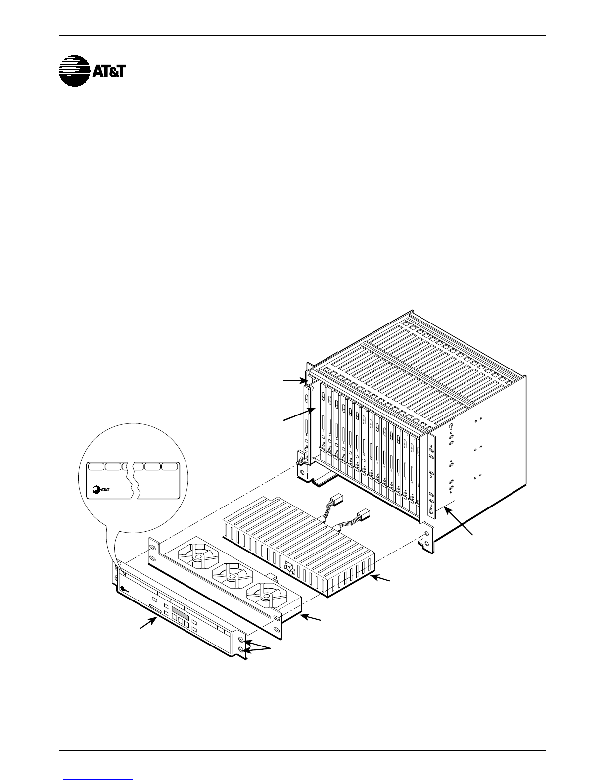
Figure 1 shows a fully loaded carrier with sixteen
circuit cards and a Shared Diagnostic Unit (SDU) in
Slot 0. When a Shared Diagnostic Control Panel (SDCP)
is used, the SDCP ribbon cable must be installed before
the power transformer unit. Refer to Document Number
3000-A2-GA31, COMSPHERE 3000 Series Carrier
Installation Manual, for SDCP installation details.
3000 Series
Carrier
P
a
r
a
dyn
e
Shared Diagnostic
Control Panel
(SDCP)
Figure 1. 3000 Series Carrier and Components
Captive
Screws
Brackets Set for
19-Inch Cabinet
AC Power
Transformer
Unit
Fan Module
(optional)
496-13596-04
13000-A2-GZ52-00 March 1996
Page 3

Power Transformer Unit
9
3
Installation
The carrier obtains low voltage ac power from the
power transformer unit, which is mounted at the bottom of
the carrier.
.
Procedure
1. At the front of the carrier, remove the cover plate
by unscrewing the four captive screws.
Captive
Screws
P
a
r
a
dyn
e
Cover Plate
496-1488
Fan Module
Power
Connector
Power
Transformer
Unit
Transformer
Output
Wires and
Connectors
495-1480
2. Place the power transformer unit on the flanges at
the bottom of the carrier. Slide the power
transformer unit into place against the rear rail of
the enclosure, guiding the transformer output
wires through the opening in the backplane.
NOTE
The power transformer unit
output wires are terminated with
plastic connectors. The power
transformer unit must be installed
so that the output wires protrude
through the backplane at the rear
of the carrier.
2 March 1996 3000-A2-GZ52-00
Page 4

3. At the rear of the carrier, use a screwdriver to
4
1
engage and tighten the two captive screws that
fasten the power transformer unit to the carrier.
5. Plug the appropriate end of the power cord into
the ac receptacle on the carrier.
P26 P25 P24 P23
J2 P22 J1 P21
P20 P19
Captive
Screws
496-1489
4. Plug the power transformer output connectors into
the P19 and P20 connectors on the backplane and
latch them.
CAUTION
The power cord contains a
3-wire grounding-type plug
which has a grounding pin.
This is a safety feature.
Grounding of the carrier is
vital to ensure safe operation.
Do not defeat the purpose of
the grounding plug by
modifying it or by using an
adapter.
Prior to installation, use an
outlet tester or voltmeter to
check the ac receptacle for
earth ground. If the power
source does not provide a
ground connection, consult an
electrician to determine
another method of grounding
the carrier before proceeding
with the installation.
AC
P20 P19
Receptacle
P26 P25 P24 P23
J2 P22 J1 P21
P20 P19
496-14804-0
6. Plug the other end of the power cord into one of
the convenience outlets inside the cabinet, or to an
external ac outlet.
7. If you are not installing a fan module or SDCP,
return to the front of the carrier and replace the
cover plate. Tighten the four captive screws.
Refer to Document Number 3000-A2-GA31,
COMSPHERE 3000 Series Carrier Installation Manual,
for additional carrier installation details.
33000-A2-GZ52-00 March 1996
 Loading...