

Paradyne Application Module 9109 OCU-DP Installation Instructions Manual

TM
1
9109 OCU-DP Application Module (APM)
Installation Instructions
Document Number 9109-A2-GN15-10
May 1999
Product Documentation on the World Wide Web
We provide complete product documentation online. This lets you search the
documentation for specific topics and print only what you need, reducing the waste of
surplus printing. It also helps us maintain competitive prices for our products.
Complete documentation for this product is available at www.paradyne.com.
Select
Library →Technical Manuals →NextEDGE Multiservices Access System
.
Select the following document:
9191-A2-GH30
NextEDGE Multiservices Access System Technical Reference
To request a paper copy of a Paradyne document:
Within the U.S.A., call 1-800-PARADYNE (1-800-727-2396)
Outside the U.S.A., call 1-727-530-8623
Before You Begin
Make sure you have:
The housing, and any associated hardware already installed
A T1 NAM already installed in Slot 01 and connected to the network
Applicable cables
A small Phillips screwdriver (#1 or #2) to install the APM
A small, flat-blade screwdriver to install the I/O card and cable connections
See the Technical Reference for additional information on:
Troubleshooting
Technical Specifications
Cables, Connectors, and Pin Assignments

496-15149
2
Package Checklist
Verify that your package contains the following:
OCU-DP APM
OCU-DP I/O card
When your equipment arrives, inspect it for physical damage and tighten any screws
that may have worked loose. Contact your sales representative immediately if there are
any signs of shipping damage or if anything is missing from your package. Otherwise,
proceed with the installation.
Equipment You May Need to Order
A DDS Network cable must be ordered for this product (either the 14 ft., Feature No.
3600F3-501, or 25 ft., Feature No. 3600-F3-502).
NOTE:
The following NAM I/O versions are required to use the OCU-DP APM:
— The SINGLE T1 NAM for Model 9161
— The DUAL T1 NAM for Model 9261
!
HANDLING PRECAUTIONS FOR STATIC-SENSITIVE DEVICES
This product is designed to protect sensitive components from
damage due to electrostatic discharge (ESD) during normal
operation. When performing installation procedures,
however, take proper static control precautions to
prevent damage to equipment. If you are not sure
of the proper static control precautions, contact
your nearest sales or service representative.
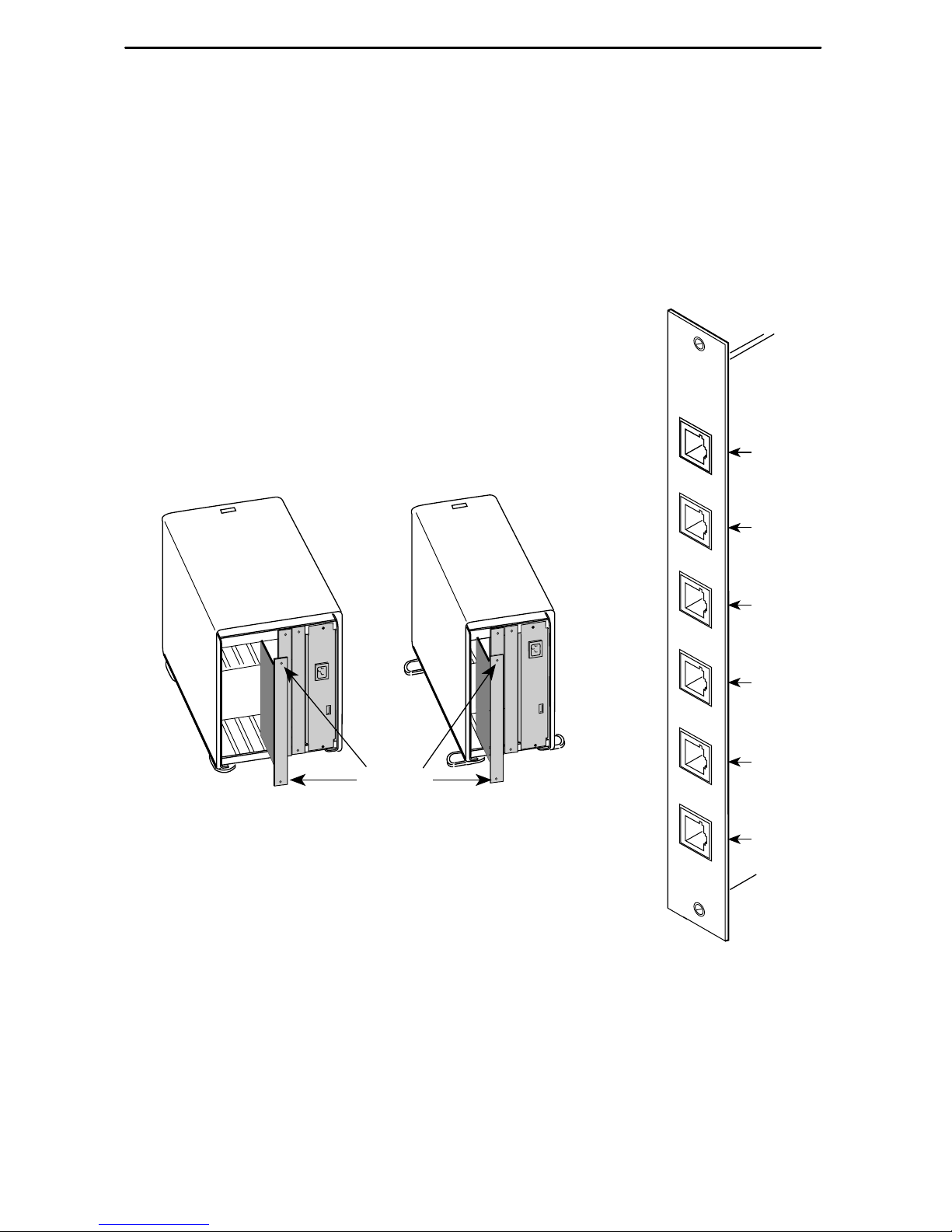
9109 OCU
PORT 1
Port 1
Port 2
98-15922
Port 3
Port 4
Port 5
Port 6
PORT 2
PORT 3
PORT 4
PORT 5
PORT 6
3
Installing the I/O Card
The I/O card provides the APM with DDS connections. The I/O card inserts directly
behind the APM that it supports. Slot numbers are identical to facilitate correct
installation.
NOTE:
For the 2-port OCU-DP APM, only Port 1 and Port 2 on the I/O card are functional.
1. Remove the I/O card from the shipping box. Handle only by
the top and bottom edges to avoid damaging the card.
2. At the rear of the housing, align the I/O card with the upper
and lower tracks of the slot. Push gently towards the
midplane until it stops and you cannot push the card any
further.
98-15150-02
Rear View
Screws
5-Slot 2-Slot
3. There are two captive screws on the I/O card. Alternately
tighten each screw until both are snug.
 Loading...