

Paradyne AIM24000, AIM24000-48 Installation Instructions Manual

AIM2-A2-GZ40-20 May 2005 1
AIM24000-48 Interface Module
Installation Instructions
Document Number AIM2-A2-GZ40-20
May 2005
Contents
Software and Firmware License Agreement ...................................................... 2
Product Documentation Online .......................................................................... 3
Release Notes ................................................................................................... 3
Warranty, Sales, Service, and Training Information ........................................... 3
AIM24000 Description ....................................................................................... 4
Unpacking and Inspecting the AIM24000 .......................................................... 4
Installing the AIM24000 in a BLC ...................................................................... 4
Verif y i ng Powe r .................................................................................................. 6
Connecting the ADSL Cables ............................................................................ 7
ADSL Remote Connection ................................................................................. 11
ADSL RJ21 Pinouts ........................................................................................... 12
Verify the ADSL Connection(s) .......................................................................... 13
LED Indicators ................................................................................................... 13
ADSL Parameters .............................................................................................. 14
AIM24000 Management .................................................................................... 14
Circuit Configuration .......................................................................................... 15
Other Configuration Options .............................................................................. 20
Data Storage ...................................................................................................... 21
Firmware Upgrades ........................................................................................... 22
Regulatory Compliance for Class A Equipment ................................................. 23
Specifications ..................................................................................................... 24

2 May 2005 AIM2-A2-GZ40-20
Software and Firmware License Agreement
The terms and conditions of this License Agreement (the “Agreement”) will apply
to the software and/or firmware (individually or collectively the “Software”)
incorporated into the Paradyne product (the “Product”) purchased by you and any
derivatives obtained from the Software, including any copy of either. If you have
executed a separate written agreement covering the Software supplied to you
under this purchase, such separate written agreement shall govern.
Paradyne Corporation (“Paradyne”) grants to you, and you (“Licensee”) agree to
accept a personal, non-transferable, non-exclusive, right (without the right to
sublicense) to use the Software, solely as it is intended and solely as incorporated
in the Product purchased from Paradyne or its authorized distributor or reseller
under the following terms and conditions:
1. Ownership: The Software is the sole property of Paradyne and/or its licensors.
The Licensee acquires no title, right or interest in the Software other than the
license granted under this Agreement.
2. Licensee shall not use the Software in any country other than the country in
which the Product was rightfully purchased except upon prior written notice to
Paradyne and an agreement in writing to additional terms.
3. The Licensee shall not reverse engineer, decompile or disassemble the
Software in whole or in part.
4. The Licensee shall not copy the Software except for a single archival copy.
5. Except for the Product warranty contained in the manual, the Software is
provided “AS IS” and in its present state and condition and Paradyne makes
no other warranty whatsoever with respect to the Product purchased by you.
THIS AGREEMENT EXPRESSLY EXCLUDES ALL OTHER WARRANTIES,
WHETHER EXPRESS OR IMPLIED, OR ORAL OR WRITTEN, INCLUDING
WITHOUT LIMITATION:
a. Any warranty that the Software is error-free, will operate uninterrupted in
your operating environment, or is compatible with any equipment or
software configurations; and
b. ANY AND ALL IMPLIED WARRANTIES, INCLUDING WITHOUT
LIMITATION IMPLIED WARRANTIES OF MERCHANTABILITY, FITNESS
FOR A PARTICULAR PURPOSE AND NON-INFRINGEMENT.
Some states or other jurisdictions do not allow the exclusion of implied
warranties on limitations on how long an implied warranty lasts, so the above
limitations may not apply to you. This warranty gives you specific legal rights,
ONCE YOU HAVE READ THIS LICENSE AGREEMENT AND AGREE TO ITS
TERMS, YOU MAY USE THE SOFTWARE AND/OR FIRMWARE INCORPORATED
INTO THE PARADYNE PRODUCT. BY USING THE PARADYNE PRODUCT YOU
SHOW YOUR ACCEPTANCE OF THE TERMS OF THIS LICENSE AGREEMENT.
IN THE EVENT THAT YOU DO NOT AGREE WITH ANY OF THE TERMS OF THIS
LICENSE AGREEMENT, PROMPTLY RETURN THE UNUSED PRODUCT IN ITS
ORIGINAL PACKAGING AND YOUR SALES RECEIPT OR INVOICE TO THE
LOCATION WHERE YOU OBTAINED THE PARADYNE PRODUCT OR THE
LOCATION FROM WHICH IT WAS SHIPPED TO YOU, AS APPLICABLE, AND YOU
WILL RECEIVE A REFUND OR CREDIT FOR THE PARADYNE PRODUCT
PURCHASED BY YOU.

AIM2-A2-GZ40-20 May 2005 3
and you may also have other rights which vary from one state or jurisdiction to
another.
6. In no event will Paradyne be liable to Licensee for any consequential,
incidental, punitive or special damages, including any lost profits or lost
savings, loss of business information or business interruption or other
pecuniary loss arising out of the use or inability to use the Software, whether
based on contract, tort, warranty or other legal or equitable grounds, even if
Paradyne has been advised of the possibility of such damages, or for any
claim by any third party.
7. The rights granted under this Agreement may not be assigned, sublicensed or
otherwise transferred by the Licensee to any third party without the prior
written consent of Paradyne.
8. This Agreement and the license granted under this Agreement shall be
terminated in the event of breach by the Licensee of any provisions of this
Agreement.
9. Upon such termination, the Licensee shall refrain from any further use of the
Software and destroy the original and all copies of the Software in the
possession of Licensee together with all documentation and related materials.
10. This Agreement shall be governed by the laws of the State of Florida, without
regard to its provisions concerning conflicts of laws.
Product Documentation Online
Complete documentation for Paradyne products is available at
www.paradyne.com. Select Support → Technical Manuals.
To order a paper copy of a Paradyne document, or to speak with a sales
representative, please call 1-727-530-2000.
Release Notes
Release notes for this product are available in the subscriber firmware area of
www.paradyne.com. Select Support → Subscriber Firmware.
Always review the relevant release notes before installing a new card.
Warranty, Sales, Service, and Training Information
Contact your local sales representative, service representative, or distributor
directly for any help needed. For additional information concerning warranty, sales,
service, repair, installation, documentation, training, distributor locations, or
Paradyne worldwide office locations, use one of the following methods:
Internet: Visit the Paradyne World Wide Web site at www.paradyne.com.
(Be sure to register your warranty at www.paradyne.com/warranty.)
Telephone: Call our automated system to receive current information by fax or
to speak with a company representative.
— Within the U.S.A., call 1-800-870-2221
— Outside the U.S.A., call 1-727-530-2340

4 May 2005 AIM2-A2-GZ40-20
AIM24000 Description
The AIM24000-48 is a 48-port ADSL2+ Annex A or Annex B inverse multiplexer. It
occupies a slot in a Model 4000 or 12000 Broadband Loop Carrier (BLC).
Unpacking and Inspecting the AIM24000
HANDLING PRECAUTIONS FOR
STATIC-SENSITIVE DEVICES
This product is designed to protect sensitive components from damage
due to electrostatic discharge (ESD) during normal operation. When
performing installation procedures, however, take proper static control
precautions to prevent damage to equipment. If you are not sure of the
proper static control precautions, contact your nearest sales or service
representative.
If there is visible damage, do not attempt to connect the device. Contact your
service or sales representative.
Installing the AIM24000 in a BLC
There must be a management module, complete with an uplink module, installed
in your BLC in order for the AIM24000 to operate.
NOTE: All of Paradyne’s BLC IP interface modules are hot swappable. Installing or
removing an interface module while the chassis is powered up does not affect the
operational status of other interface modules within the chassis.
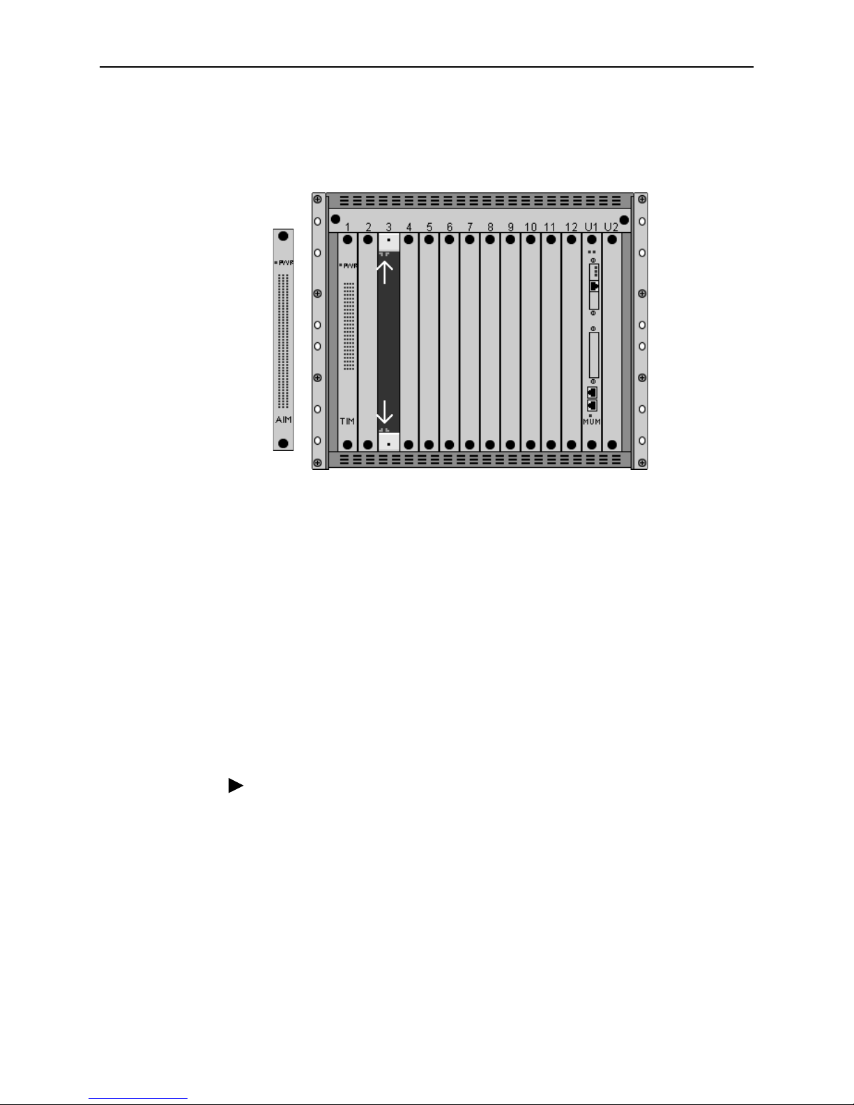
12-Slot BLC
The 12000 and 12000E BLCs are fourteen slot chassis. Slots 1–12 are reserved
for interface modules (such as the AIM24000), and the remaining slots (13 and 14
in the 12000 and U1 and U2 in the 12000E) are reserved for management
modules.
NOTE: Although the AIM24000 can be installed in both the 12000 and the 12000E
BLC, the 12000 has the capability to support AIM24000 ports 1–24 only. In order
to make use of all 48 ports, you must install the AIM24000 in a 12000E.
Procedure
To install the AIM24000 in a 12-slot BLC:
1. Select a slot for installation. The AIM24000 may be placed in any available
slot, 1–12. Remove the cover plate from the chosen slot by turning the
fastening screws counterclockwise with a screwdriver and then gently sliding
the cover plate out of the chassis.
CAUTION: If a cover plate is removed from slot 1–12 of a 12000 or 12000E
BLC, it must be replaced with an interface module. Do not operate your BLC
with an empty slot.
!
AIM2-A2-GZ40-20 May 2005 5
2. With the AIM24000 Printed Circuit Board (PCB) facing right and the AIM24000
model name on the lower edge of the faceplate, align the upper and lower
edges of the PCB with the slot module guides.
3. Slide the AIM24000 into the chassis until it is fully seated. Do not use
excessive force.
4. Tighten the fastening screws on the AIM24000 faceplate by turning them
clockwise with a screwdriver, just until snug. Do not over-tighten the fastening
screws.
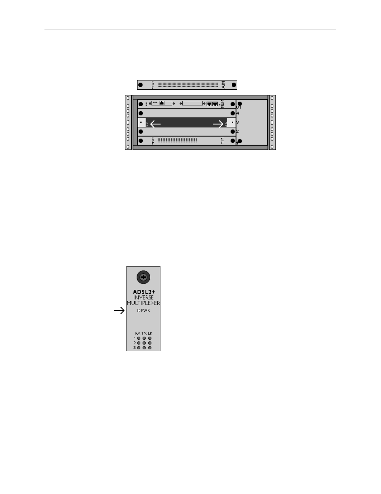
4-Slot BLC
The 4000 and 4000E are five-slot chassis. Slots 1–4 are reserved for interface
modules (such as the AIM24000), and the remaining slot (slot 5 in the 4000 and
slot U1 in the 4000E) is reserved for a management module.
NOTE: Although the AIM24000 can be installed in both the 4000 and the 4000E
BLCs, the 4000 has the capability to support AIM24000 ports 1–24 only; in order
to make use of all 48 ports, you must install the AIM24000 in a 4000E.
Procedure
To install the AIM24000 in a 4-slot BLC:
1. Select a slot for installation. The AIM24000 may be placed in any slot, 1–4.
Remove the blank plate from the chosen slot by turning the fastening screws
counter-clockwise with a Phillips screwdriver and then gently sliding the blank
plate out of the chassis
CAUTION: If a blank plate is removed from slot 1–4 on a 4000 or 4000E BLC,
it must be replaced with an interface module. Do not operate your BLC with
an empty slot.
6 May 2005 AIM2-A2-GZ40-20
2. With the AIM24000 Printed Circuit Board (PCB) facing up and the AIM24000
faceplate model name on the right, align the edges of the PCB with the slot
module guides on both sides.
3. Slide the AIM24000 into the chassis until it is fully seated. Do not use
excessive force.
4. Tighten the fastening screws on the AIM24000 faceplate. Do not over-tighten
the fastening screws.
Verifying Power
If you have not already powered up your BLC, do so now.
The PWR (power) LED on the AIM24000 faceplate illuminates solid green to
indicate the AIM24000 is receiving power.
AIM2-A2-GZ40-20 May 2005 7
Connecting the ADSL Cables
12-Slot BLC
NOTE: No configuration is necessary for the AIM24000 to operate at default
settings. However, if you wish to run your subscriber connections at settings other
than the factory defaults, configure the AIM24000 prior to ADSL connection. Refer
to AIM24000 Management on page 14 for further information.
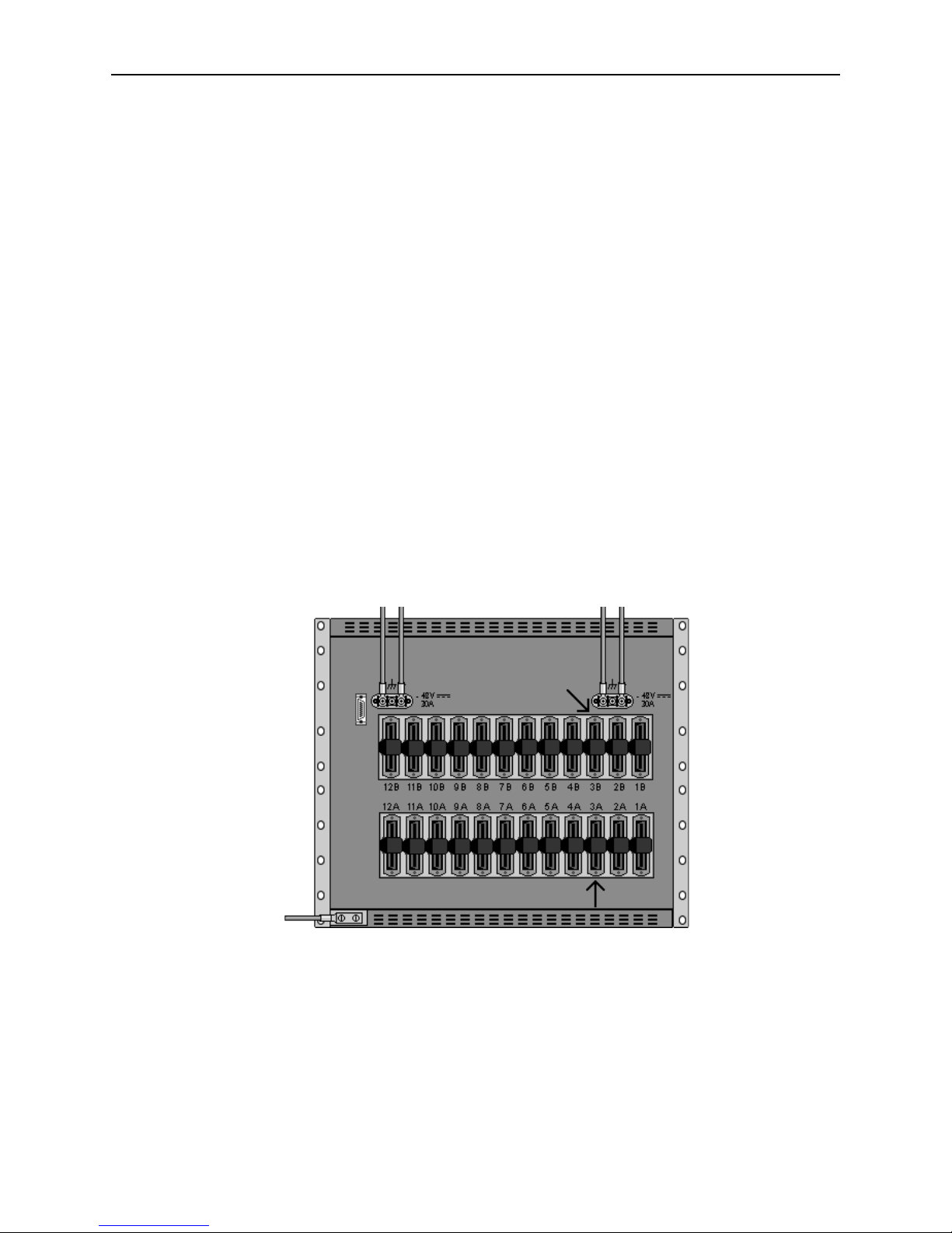
Subscriber lines must be connected according to the BLC slot in which the
AIM24000 was installed. Interface module slots 1–12 run from left to right when
you are facing the front of the chassis; the corresponding RJ21 ports are directly
behind each slot on the back of the chassis (1–12, right to left, when you are facing
the back of the chassis). Each interface module slot on the 12000E has two
corresponding female RJ21 connectors: the bottom row of connectors (A) provides
the ADSL connection for AIM24000 ports 1–24 and the top row of RJ21
connectors (B) provides the ADSL connection for ports 25–48.
For example, if the AIM24000 is installed in Slot 3 of a 12000E, ADSL cables must
be connected to:
RJ21 Connector 3B for AIM24000 ports 25–48
RJ21 Connector 3A for AIM24000 ports 1–24
NOTE: The 12000 has only one RJ21 connector for each interface module slot.
These connectors support ports 1–24 of the AIM24000; ports 25–48 cannot be
connected in a 12000. The 12000E supports all 48 ports.
8 May 2005 AIM2-A2-GZ40-20
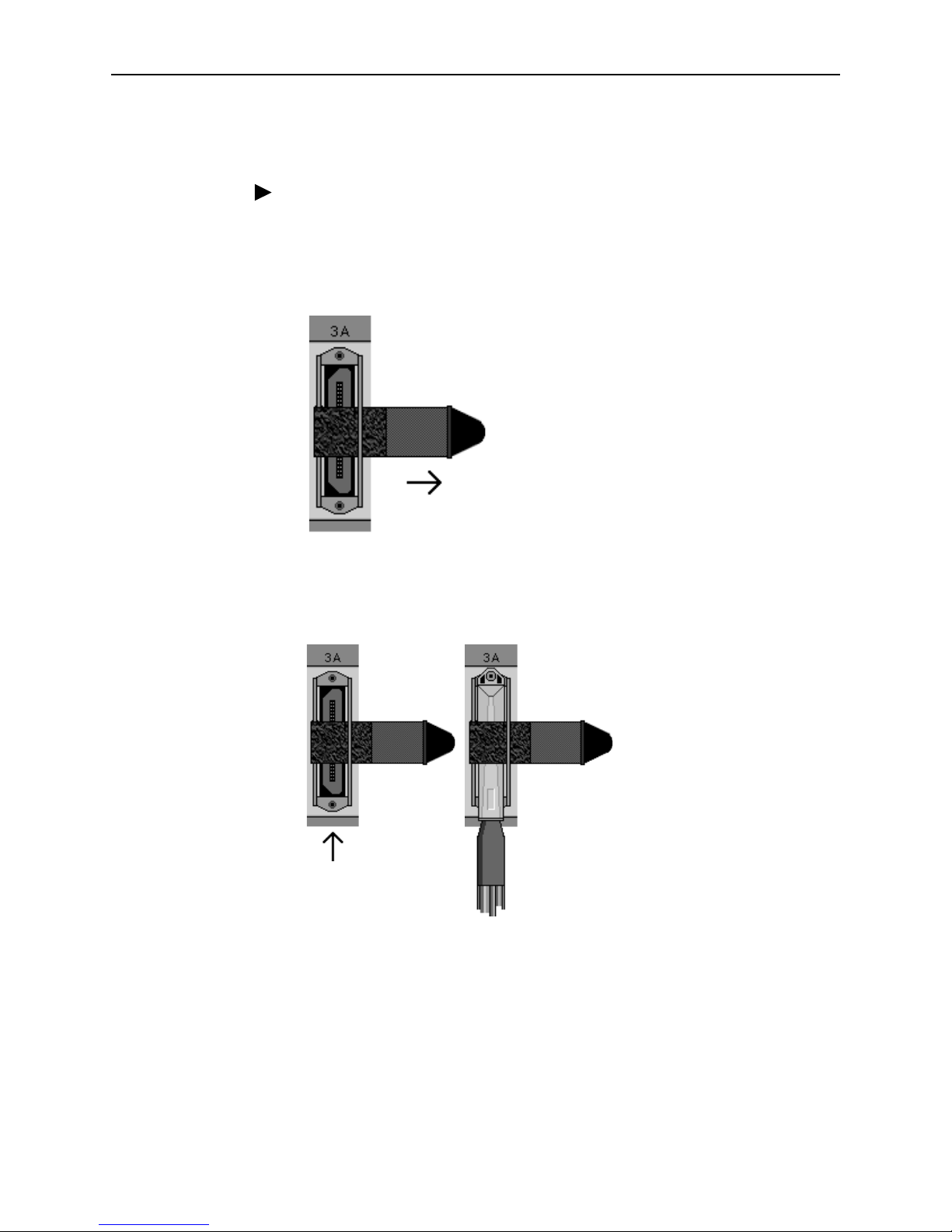
Attaching RJ21 Connectors to the 12-Slot BLC
Procedure
1. Detach the hook and loop fastener strap from the RJ21 receptacle. Lift the
hook and loop fastener tab on the left and pull the strap open towards the
right, leaving it looped under the right side of the connector frame.
2. Slide the RJ21 plug of your ADSL cable underneath the hook and loop
fastener from the bottom, and press it firmly into the RJ21 receptacle on the
chassis.
3. Pull the hook and loop fastener strap to the right, making sure that it is snug
against the connector, then pull the strap back towards the left, such that the
hook and loop fastener layers stick to one another across the top of the
connector. Tuck the tab at the end of the strap down to the left of the connector
frame so that it is out of the way of other connections.
4. Screw the top of the RJ21 cable connector into the jackscrew at the top of the
RJ21 connector frame on the chassis.
 Loading...