

Paradyne 3150, 3151, ACCULINK CSU 3150-A4, ACCULINK CSU 3151 Owner's Manual

ACCULINK® CSU
Models 3150-A4 and 3151
Operator’s Guide
Document No. 3150-A2-GB24-10
March 2001

Copyright © 2001 Paradyne Corporation.
All rights reserved.
Printed in U.S.A.
Notice
This publication is protected by federal copyright law. No part of this publication may be copied or distributed,
transmitted, tr ansc ribed, store d in a re trie v al syst em, or tr ans lated into a n y huma n or com puter l anguag e in an y form or
by any means, electronic, mecha nic al , ma gnetic, manual or otherwis e , or dis cl os ed to third parties witho ut th e express
written permission of Paradyne Corporation, 8545 126th Ave. N., Largo, FL 33773.
Paradyne Corporation makes no representation or warranties with respect to the contents hereof and specifically
disclaims any implied warranties of merchantability or fitness for a particular purpose. Further, Paradyne Corporation
reserves the right to revise this publication and to make changes from time to time in the contents hereof without
obligation of Paradyne Corporation to notify any person of such revision or changes.
Changes and enhancements to the product and to the information herein will be documented and issued as a new
release to this manual.
Warranty, Sales, Service, and Training Information
Contact your local sales representative, service representative, or distributor directly for any help needed. For
additional information concerning warranty, sales, service, repair, installation, documentation, training, distributor
locations, or Paradyne worldwide office lo cations, use one of the following methods:
Internet:
www.paradyne.com/warranty
Telephone:
representative.
— Within the U.S.A., call 1-800-870-2221
— Outside the U.S.A., call 1-727-530-2340
Visit the Paradyne World Wide Web s i te at
.)
Call our automated system to receive current information by fax or to speak with a company
www.paradyne.com
. (Be sure to register your warranty at
Trademarks
ACCULINK, COMSPHERE, FrameSaver, Hotwire, MVL, NextEDGE, OpenLane, and Performance Wizard are
registered trademarks of Paradyne Corporation. ReachDSL and TruePut are trademarks of Paradyne Corporation. All
other products and s ervices m en tion ed here in are the trademarks, service ma rks , registered trademarks, or registered
service marks of their respective owners.
Document Feedback
We welcome your comments and suggestions about this document. Please mail them to Technical Publications,
Paradyne Corporation, 8545 126th Ave. N., Largo, FL 33773, or send e-mail to
number and title of this document in your correspondence. Please include your name and phone number if you are
willing to provide additional clarification.
userdoc@paradyne.com
. Include the
March 2001 3150-A2-GB24-10
A

!
Importan t Safety Instructions
1. Read and follow all warning notices and instructions marked on the product or included in the manual.
2. This product (when not powered by the optional direct feed cable) is intended to be used with a 3-wire grounding
type plug – a plug which has a grounding pin. This is a safety feature. Equipment grounding is vital to ensure safe
operation. Do not defeat the purpose of the grounding type plug by modifying the plug or using an adapter.
Prior to installation , u se an o utl et tes ter or a voltmeter to chec k t he ac re cep tac le for the presence o f e arth ground .
If the receptacle is not properly grounded, the installation must not continue until a qualified electrician has
corrected the problem.
If a 3-wire grounding type power source is not available, consult a qualified electrician to determine another
method of grounding the equipment.
3. Slots and openings in the cabinet are provided for ventilation. To ensure reliable operation of the product and to
protect it from overheating, these slots and openings must not be blocked or covered.
4. Do not allow anything to rest on the power cord and do not locate the product where persons will walk on the
power cord.
5. Do not attempt to service this product yourself, as opening or re moving covers may e xp os e you to dangerous high
voltage points or other risks. Refer all servicing to qualified service personnel.
6. General purpose cables are provided with this product. Special cables, which may be required by the regulatory
inspection authority for the installation site, are the responsibility of the customer.
7. When installed in the final configuration, the product must comply with the applicable Safety Standards and
regulatory requirements of the country in which it is installed. If necessary, consult with the appropriate regulatory
agencies and inspection authorities to ensure compliance.
8. A rare phenomenon ca n create a v oltag e potent ial betwee n the earth groun ds of two or more b uil dings . If pro ducts
installed in separate buildings are
Consult a qualified electrical consultant to determine whether or not this phenomenon exists and, if necessary,
implement corrective action prior to interconnecting the products.
9. The Model 3150’s input power to the AC voltage configuration of this product must be provided by a UL Listed or
CSA Certified, Class 2 transformer. Input power to the DC voltage configurations of this product must be provided
by a National Electric Code (NEC) or a Canadian Electric Code (CEC), Part 1, Class 2 circuit.
10. This product contains a coin cell lithium battery that is only to be replaced at the factory.
danger of explosion if the battery is incorrectly replaced. Replace only with the same type. Dispose of used
batteries according to the battery manufacturer’s instructions.
remplacement incorrect de la batterie. Remplacer uniquement avec une batterie du même type. Mettre au rebut
les batteries usagées conformément aux instructions du fabricant.
In addition, if the equipment is to be used with telecommunications circuits, take the following precautions:
— Never install telephone wiring during a lightning storm.
— Never install telephone jacks in wet locations unless the jack is specifically designed for wet locations.
— Neve r tou ch uninsulated telephone wire s or terminals unless the telep hon e line has been disconn ec ted at t he
network interface.
— Use caution when installing or modifying telephone lines.
— Av oid usi ng a tele pho ne (othe r than a co rdless type) du ring an el ectrical s torm. There ma y be a remo te risk of
electric shock from lightning.
— Do not use the telephone to report a gas leak in the vicinity of the leak.
interconnected
, the voltage potential may cause a hazardous condition.
There is a
Attention:
Caution:
Il y a danger d’explosion s’il y a
3150-A2-GB24-10 March 2001
B

!
UNITED STATES – EMI NOTICE:
This equipment has been tested and found to comply with the limits for a Class A digital device, pursuant
to Part 15 of the FCC rules. These limits are designed to provide reasonable protection against harmful
interference when the equipment is operated in a commercial environment. This equipment generates,
uses, and can radiate radio frequency energy and, if not installed and used in accordance with the
instruction manual, ma y cause harmful interf erence to radio comm unications. Ope ration of this equipment
in a residential area is likely to cause harmful interference in which case the user will be required to
correct the interference at his own expense.
The authority to operate this equipment is conditioned by the requirements that no modifications will be
made to the equipment unless the changes or modifications are expressly approved by Paradyne
Corporation.
!
CANADA – EMI NOTICE:
This Class A digital apparatus meets all requirements of the Canadian interference-causing equipment
regulations.
Cet appareil numérique de la classe A respecte toutes les exigences du réglement sur le matérial
brouilleur du Canada.
March 2001 3150-A2-GB24-10
C

Government Requirements and Equipment Return
Certain governments require that instructions pertaining to CSU and modem connection to the telephone network be
included in the installation and operation manual. Specific instructions are listed in the following sections.
United States
NOTICE TO USERS OF THE UNITED STATES TELEPHONE NETWORK
1. This equipment complies with Part 68 of the FCC rules. On the equipment is a label that contains, among other
information, the FCC registration number and ringer equivalence number (REN) for this equipment. The label is
located on the bottom of the 3150 CSU, and on the 3151 CSU’s ci rcu it c ard. If requested, this information m us t be
provided to the telephone company.
2. There are two types of telephone lines associated with the standalone equipment. The T1 network connection
should be made using a Universal Service Order Code (USOC) type RJ48C jack. The Service Order Code 6.0F
should be specified to the telephone company when ordering the T1 line. In addition, the proper Facility Interface
Code must be specified to the Telephone Company. The CSU can be configured to support any of the following
framing format and line signaling techniques. The CSU’s configuration must correspond to the T1 line’s
parameters. The 3150 CSU’s internal modem connects to the Public Switched Telephone Network using a USOC
Type RJ11C jack. The Facility Interface C ode 02LS2 along with the RJ11C jack should be speci fied to the
telephone comp an y w h en orde ring a dial line for the m ode m. The 3151 CSU connec ts to the T1 network using the
multi-line USOC-type RJ48H jack and does not have a PSTN interface.
315x CSU Facility Interface Codes
Code Description
04DU9-BN 1.544 Mbps superframe format (SF) without line power
04DU9-DN 1.54 4 Mbps SF and B8ZS without line power
04DU9-1KN 1.544 Mbps ANSI ESF without line power
04DU-1SN 1.544 Mbps ANSI ESF and B8ZS without line power
3. The ringer equival ence nu mber (R EN) is used to determine the q uantity of de vi ces w hich may be connected to the
telephone line. Excessive RENs on the telephone line may result in the devices not ringing in response to an
incoming call. In most, but not all areas, the sum of the RENs should not exceed five (5.0). To be certain of the
number of devices that may be connected to the line, as determined by the total RENs, contact the telephone
company to determine th e maximum RENs for the calling area.
4. If the 315x CSU causes harm to the telephone network, the telephone company will notify you in advance that
temporary discontinuance of service may be required. But if advance notice is not practical, the telephone
company will n otify th e cust omer as soon a s poss ib le . Also, you will be advised of your right to file a c ompl aint with
the FCC if you believe it is necessary.
5. The telephone com pany may mak e changes in its fac ili tie s , equipment, operations, or procedures that c ou ld a ffect
the operation of the equipment. If this happens, the telephone company will provide advance notice in order for
you to make the necessary modifications in order to maintain uninterrupted service.
6. If you experience trouble with this equi pment, please contact your sales or service rep r es enta tive (as appropriate)
for repair or warranty information. If the product needs to be returned to the company service center for repair,
contact them directly for return instructions using one of the following methods:
—
Internet:
—
Telephone:
company representa tive.
Within the U.S.A., call 1-800-870-2221
Outside the U.S.A., call 1-727-530-2340
Visit the Paradyne World Wide Web site at http://www.paradyne.com
Call our automated response system to receive current information via fax or to speak with a
If the trouble is causing harm to the telephone network, the telephone company may request that you remove the
equipment from the network until the problem is resolved.
3150-A2-GB24-10 March 2001
D

7. The equipment’s modem cannot be used on public coin service provi ded by the telepho ne compa ny. Connection to
Party Line Service is su bje ct to st ate t ariffs. (Conta ct the st ate pu bl ic uti lity comm ission, pub l ic se rvice commis sion
or corporation commission for information.)
8. FCC compliant telephone line cords with modular plugs are provided with this equipment. This equipment is
designed to be connected to the telephone network or premises wiring using a compatible modular jack which is
Part 68 compliant.
Canada
NOTICE TO USERS OF THE CANADIAN TELEPHONE NETWORK
The Canadian Department of Communications label identifies certified equipment. This certification means that the
equipment meets certain telecommunications network protective, operational and safety requirements. The
Department does not guarantee the equipment will operate to the user’s satisfaction.
Before installing this equipment, users should ensure that it is permissible to be connected to the facilities of the local
telecommunications company. The equipment must also be installed using an acceptable method of connection. In
some cases, the company’s inside wi ring ass oc ia t ed with a single line individ ual service may be e xte nde d by means of
a certified connector assembly (telephone extension cord). The customer should be aware that compliance with the
above conditions may not prevent degradation of service in some situations.
Repairs to certified equipment should be made by an authorized Canadian maintenance facility designated by the
supplier. Any repairs or alterations made by the user to this equipment, or equipment malfunctions, may give the
telecommunications company cause to request to disconnect the equipment.
CAUTION:
Users should not attempt to make such connections themselves, but should contact the appropriate
electric inspection authority, or electrician, as appropriate.
If your equipment is in need of repair, return it using the procedures described on page A in the front of this document.
March 2001 3150-A2-GB24-10
E

Contents
About This Guide
1 Introduction
Document Purpose and Intended Audience . . . . . . . . . . . . . . . . . . . . vii
Document Summary . . . . . . . . . . . . . . . . . . . . . . . . . . . . . . . . . . . . . . vii
Product-Related Documents . . . . . . . . . . . . . . . . . . . . . . . . . . . . . . . . viii
Reference Documents . . . . . . . . . . . . . . . . . . . . . . . . . . . . . . . . . . . . . ix
Overview . . . . . . . . . . . . . . . . . . . . . . . . . . . . . . . . . . . . . . . . . . . . . . . 1-1
Features. . . . . . . . . . . . . . . . . . . . . . . . . . . . . . . . . . . . . . . . . . . . . . . . 1-1
Alarm Message Capability. . . . . . . . . . . . . . . . . . . . . . . . . . . . . . . 1-2
Front Panel Emulation . . . . . . . . . . . . . . . . . . . . . . . . . . . . . . . . . . 1-2
Integral Modem . . . . . . . . . . . . . . . . . . . . . . . . . . . . . . . . . . . . . . . 1-2
Asynchronous Terminal Interface Support . . . . . . . . . . . . . . . . . . 1-2
Telnet Access . . . . . . . . . . . . . . . . . . . . . . . . . . . . . . . . . . . . . . . . 1-2
SNMP Management Support. . . . . . . . . . . . . . . . . . . . . . . . . . . . . 1-2
Physical Description. . . . . . . . . . . . . . . . . . . . . . . . . . . . . . . . . . . . . . . 1-3
Standalone CSU Front Panel . . . . . . . . . . . . . . . . . . . . . . . . . . . . 1-3
Standalone CSU Rear Panel. . . . . . . . . . . . . . . . . . . . . . . . . . . . . 1-4
2 Installation
Overview . . . . . . . . . . . . . . . . . . . . . . . . . . . . . . . . . . . . . . . . . . . . . . . 2-1
Application Example. . . . . . . . . . . . . . . . . . . . . . . . . . . . . . . . . . . . . . . 2-1
SNMP or Telnet Connection Examples . . . . . . . . . . . . . . . . . . . . . . . . 2-2
Important Instructions. . . . . . . . . . . . . . . . . . . . . . . . . . . . . . . . . . . . . . 2-4
Installation Steps . . . . . . . . . . . . . . . . . . . . . . . . . . . . . . . . . . . . . . . . . 2-4
Cabling Examples . . . . . . . . . . . . . . . . . . . . . . . . . . . . . . . . . . . . . . . . 2-5
Power-On Self-Test . . . . . . . . . . . . . . . . . . . . . . . . . . . . . . . . . . . . . . . 2-6
3150-A2-GB24-10 March 2001
i

Contents
3 Using the Front Panel
Overview . . . . . . . . . . . . . . . . . . . . . . . . . . . . . . . . . . . . . . . . . . . . . . . 3-1
Front Panel. . . . . . . . . . . . . . . . . . . . . . . . . . . . . . . . . . . . . . . . . . . . . . 3-1
LCD . . . . . . . . . . . . . . . . . . . . . . . . . . . . . . . . . . . . . . . . . . . . . . . . 3-2
Keypad. . . . . . . . . . . . . . . . . . . . . . . . . . . . . . . . . . . . . . . . . . . . . . 3-3
Test Jacks . . . . . . . . . . . . . . . . . . . . . . . . . . . . . . . . . . . . . . . . . . . 3-4
LEDs . . . . . . . . . . . . . . . . . . . . . . . . . . . . . . . . . . . . . . . . . . . . . . . 3-5
Displaying LED Conditions. . . . . . . . . . . . . . . . . . . . . . . . . . . . . . . . . . 3-8
Displaying Unit Identity. . . . . . . . . . . . . . . . . . . . . . . . . . . . . . . . . . . . . 3-9
Resetting the CSU . . . . . . . . . . . . . . . . . . . . . . . . . . . . . . . . . . . . . . . . 3-11
Download Operations. . . . . . . . . . . . . . . . . . . . . . . . . . . . . . . . . . . . . . 3-11
4 Configuration
Overview . . . . . . . . . . . . . . . . . . . . . . . . . . . . . . . . . . . . . . . . . . . . . . . 4-1
Setting Customer Identification . . . . . . . . . . . . . . . . . . . . . . . . . . . . . . 4-2
Changing Configuration Options . . . . . . . . . . . . . . . . . . . . . . . . . . . . . 4-3
Displaying/Editing Configuration Options . . . . . . . . . . . . . . . . . . . 4-4
Saving Edit Changes . . . . . . . . . . . . . . . . . . . . . . . . . . . . . . . . . . . 4-6
Configuring the 10BaseT Port . . . . . . . . . . . . . . . . . . . . . . . . . . . . . . . 4-7
Setting the 10BaseT Port IP Address . . . . . . . . . . . . . . . . . . . . . . 4-8
Setting the 10BaseT Port Subnet Mask. . . . . . . . . . . . . . . . . . . . . 4-9
Setting the Default Gateway Address . . . . . . . . . . . . . . . . . . . . . . 4-10
Configuring the COM Port or Modem Port for SNMP or
Telnet Access. . . . . . . . . . . . . . . . . . . . . . . . . . . . . . . . . . . . . . . . . . . . 4-11
Selecting the Port . . . . . . . . . . . . . . . . . . . . . . . . . . . . . . . . . . . . . 4-12
Setting the COM Port or MODEM Port IP Address . . . . . . . . . . . . 4-13
Selecting the Link Layer Protocol . . . . . . . . . . . . . . . . . . . . . . . . . 4-15
Specifying the Community Name(s) and Access Type(s) . . . . . . . . . . 4-17
Configuring SNMP Traps. . . . . . . . . . . . . . . . . . . . . . . . . . . . . . . . . . . 4-19
Enabling SNMP Trap Messages . . . . . . . . . . . . . . . . . . . . . . . . . . 4-19
Selecting the Number of Trap Managers. . . . . . . . . . . . . . . . . . . . 4-20
Configuring a Destination for SNMP Traps . . . . . . . . . . . . . . . . . . 4-21
Enabling the Communication Port for Carrier-Mounted CSUs. . . . . . . 4-22
Deactivating the Alarm Relay for Carrier-Mounted CSUs . . . . . . . . . . 4-25
March 2001 3150-A2-GB24-10
ii

5 Security
Overview . . . . . . . . . . . . . . . . . . . . . . . . . . . . . . . . . . . . . . . . . . . . . . . 5-1
Establishing Access Security on a Port . . . . . . . . . . . . . . . . . . . . . . . . 5-2
Setting a Password . . . . . . . . . . . . . . . . . . . . . . . . . . . . . . . . . . . . . . . 5-3
Entering a Password to Gain Access. . . . . . . . . . . . . . . . . . . . . . . . . . 5-4
Acquiring/Releasing the User Interface . . . . . . . . . . . . . . . . . . . . . . . . 5-5
Acquiring the Active User Interface . . . . . . . . . . . . . . . . . . . . . . . . 5-5
Releasing the Active User Interface . . . . . . . . . . . . . . . . . . . . . . . 5-6
Enabling/Disabling the Front Panel . . . . . . . . . . . . . . . . . . . . . . . . . . . 5-7
User Interface Access Security for Standalone CSUs . . . . . . . . . . . . . 5-9
Changing User Interface Access Security . . . . . . . . . . . . . . . . . . . 5-10
6 Using the Integral Modem
Using the Integral Modem in Standalone CSUs. . . . . . . . . . . . . . . . . . 6-1
Entering Numbers in the Phone Directories. . . . . . . . . . . . . . . . . . . . . 6-2
Initiating a Call for Front Panel Pass-Through Operation . . . . . . . . . . 6-4
Initiating a Call for PC, ASCII Terminal/Printer, or SNMP Operation . . 6-6
Disconnecting the Modem Connection . . . . . . . . . . . . . . . . . . . . . . . . 6-7
Contents
7 Monitoring and Troubleshoo ti n g
Overview . . . . . . . . . . . . . . . . . . . . . . . . . . . . . . . . . . . . . . . . . . . . . . . 7-1
Self-Test Health Messages . . . . . . . . . . . . . . . . . . . . . . . . . . . . . . . . . 7-2
Device Health and Status Messages . . . . . . . . . . . . . . . . . . . . . . . . . . 7-4
Performance Reports. . . . . . . . . . . . . . . . . . . . . . . . . . . . . . . . . . . . . . 7-6
Ethernet Statistics . . . . . . . . . . . . . . . . . . . . . . . . . . . . . . . . . . . . . . . . 7-11
Alarms . . . . . . . . . . . . . . . . . . . . . . . . . . . . . . . . . . . . . . . . . . . . . . . . . 7-12
SNMP Traps. . . . . . . . . . . . . . . . . . . . . . . . . . . . . . . . . . . . . . . . . . . . . 7-13
Troubleshooting . . . . . . . . . . . . . . . . . . . . . . . . . . . . . . . . . . . . . . . . . . 7-15
3150-A2-GB24-10 March 2001
iii

Contents
8Testing
Overview . . . . . . . . . . . . . . . . . . . . . . . . . . . . . . . . . . . . . . . . . . . . . . . 8-1
Test Jacks . . . . . . . . . . . . . . . . . . . . . . . . . . . . . . . . . . . . . . . . . . . . . . 8-2
Test Jack Configuration (Model 3150). . . . . . . . . . . . . . . . . . . . . . 8-4
Test Commands. . . . . . . . . . . . . . . . . . . . . . . . . . . . . . . . . . . . . . . . . . 8-5
Remote Loopback Tests . . . . . . . . . . . . . . . . . . . . . . . . . . . . . . . . . . . 8-5
Local Loopback Tests . . . . . . . . . . . . . . . . . . . . . . . . . . . . . . . . . . . . . 8-6
Line Loopback (LLB) . . . . . . . . . . . . . . . . . . . . . . . . . . . . . . . . . . . 8-7
Payload Loopback (PLB). . . . . . . . . . . . . . . . . . . . . . . . . . . . . . . . 8-8
DTE Loopback (DLB). . . . . . . . . . . . . . . . . . . . . . . . . . . . . . . . . . . 8-9
Repeater Loopback (RLB). . . . . . . . . . . . . . . . . . . . . . . . . . . . . . . 8-10
Aborting Loopbacks. . . . . . . . . . . . . . . . . . . . . . . . . . . . . . . . . . . . 8-11
Test Patterns . . . . . . . . . . . . . . . . . . . . . . . . . . . . . . . . . . . . . . . . . . . . 8-12
Sending Test Patterns . . . . . . . . . . . . . . . . . . . . . . . . . . . . . . . . . . 8-12
Monitoring Test Patterns . . . . . . . . . . . . . . . . . . . . . . . . . . . . . . . . 8-13
Aborting Test Patterns. . . . . . . . . . . . . . . . . . . . . . . . . . . . . . . . . . 8-14
Lamp Test . . . . . . . . . . . . . . . . . . . . . . . . . . . . . . . . . . . . . . . . . . . . . . 8-15
Starting a Lamp Test . . . . . . . . . . . . . . . . . . . . . . . . . . . . . . . . . . . 8-15
Aborting a Lamp Test . . . . . . . . . . . . . . . . . . . . . . . . . . . . . . . . . . 8-16
Displaying CSU Test Status. . . . . . . . . . . . . . . . . . . . . . . . . . . . . . . . . 8-17
A Front Panel Menu
B Technical Specifications
Overview . . . . . . . . . . . . . . . . . . . . . . . . . . . . . . . . . . . . . . . . . . . . . . . B-1
C Configuration Options
Overview . . . . . . . . . . . . . . . . . . . . . . . . . . . . . . . . . . . . . . . . . . . . . . . C-1
DTE Interface Configuration Options . . . . . . . . . . . . . . . . . . . . . . . . . . C-2
Network Interface Configuration Options . . . . . . . . . . . . . . . . . . . . . . . C-3
General Configuration Options. . . . . . . . . . . . . . . . . . . . . . . . . . . . . . . C-6
User Interface Configuration Options. . . . . . . . . . . . . . . . . . . . . . . . . . C-7
Alarm Configuration Options . . . . . . . . . . . . . . . . . . . . . . . . . . . . . . . . C-17
Management Configuration Options . . . . . . . . . . . . . . . . . . . . . . . . . . C-21
March 2001 3150-A2-GB24-10
iv

D Configuration Worksheets
Configuration Worksheets . . . . . . . . . . . . . . . . . . . . . . . . . . . . . . . . . . D-1
E Pin Assignments
Overview . . . . . . . . . . . . . . . . . . . . . . . . . . . . . . . . . . . . . . . . . . . . . . . E-1
Power Input Connector . . . . . . . . . . . . . . . . . . . . . . . . . . . . . . . . . . . . E-1
T1 Network Interface . . . . . . . . . . . . . . . . . . . . . . . . . . . . . . . . . . . . . . E-2
DTE Interface. . . . . . . . . . . . . . . . . . . . . . . . . . . . . . . . . . . . . . . . . . . . E-4
MODEM Port Interface. . . . . . . . . . . . . . . . . . . . . . . . . . . . . . . . . . . . . E-5
10BaseT Connector . . . . . . . . . . . . . . . . . . . . . . . . . . . . . . . . . . . . . . . E-6
COM Port Interface . . . . . . . . . . . . . . . . . . . . . . . . . . . . . . . . . . . . . . . E-7
Serial Crossover Cable . . . . . . . . . . . . . . . . . . . . . . . . . . . . . . . . . . . . E-9
F SNMP MIB Objects
Contents
Overview . . . . . . . . . . . . . . . . . . . . . . . . . . . . . . . . . . . . . . . . . . . . . . . F-1
MIB II (RFC 1213) . . . . . . . . . . . . . . . . . . . . . . . . . . . . . . . . . . . . . . . . F-2
System Group, MIB II . . . . . . . . . . . . . . . . . . . . . . . . . . . . . . . . . . F-3
Interface Group, MIB II . . . . . . . . . . . . . . . . . . . . . . . . . . . . . . . . . F-4
IP Group, MIB II. . . . . . . . . . . . . . . . . . . . . . . . . . . . . . . . . . . . . . . F-8
ICMP Group, MIB II . . . . . . . . . . . . . . . . . . . . . . . . . . . . . . . . . . . . F-11
TCP Group, MIB II . . . . . . . . . . . . . . . . . . . . . . . . . . . . . . . . . . . . . F-11
UDP Group, MIB II. . . . . . . . . . . . . . . . . . . . . . . . . . . . . . . . . . . . . F-11
Transmission Group, MIB II. . . . . . . . . . . . . . . . . . . . . . . . . . . . . . F-11
SNMP Group, MIB II . . . . . . . . . . . . . . . . . . . . . . . . . . . . . . . . . . . F-11
DS1/E1 MIB (RFC 1406) . . . . . . . . . . . . . . . . . . . . . . . . . . . . . . . . . . . F-12
Near End Group, DS1/E1 MIB. . . . . . . . . . . . . . . . . . . . . . . . . . . . F-12
Far End Group, DS1/E1 MIB . . . . . . . . . . . . . . . . . . . . . . . . . . . . . F-16
DS1 Fractional Group, DS1/E1 MIB . . . . . . . . . . . . . . . . . . . . . . . F-16
RS-232-like MIB (RFC 1317) . . . . . . . . . . . . . . . . . . . . . . . . . . . . . . . . F-17
General Port Table, RS-232-like MIB . . . . . . . . . . . . . . . . . . . . . . F-17
Asynchronous Port Table, RS-232-like MIB . . . . . . . . . . . . . . . . . F-18
Synchronous Port Table, RS-232-like MIB . . . . . . . . . . . . . . . . . . F-19
Generic-Interface MIB Extensions (RFC 1229) . . . . . . . . . . . . . . . . . . F-20
Generic Interface Test Table, Generic Interface MIB . . . . . . . . . . F-20
Enterprise MIB . . . . . . . . . . . . . . . . . . . . . . . . . . . . . . . . . . . . . . . . . . . F-21
Correlation between Menu Commands and SNMP Objects . . . . . . . . F-21
3150-A2-GB24-10 March 2001
v

Contents
G IP Network Addressing Scenarios
Overview . . . . . . . . . . . . . . . . . . . . . . . . . . . . . . . . . . . . . . . . . . . . . . . G-1
Standalone at the Central Site . . . . . . . . . . . . . . . . . . . . . . . . . . . . . . . G-2
Local Carrier and Remote Standalone. . . . . . . . . . . . . . . . . . . . . . . . . G-3
Local and Remote Carriers – Different Subnets . . . . . . . . . . . . . . . . . G-4
Local and Remote Carriers – Same Subnet . . . . . . . . . . . . . . . . . . . . G-5
Multiple NMSs . . . . . . . . . . . . . . . . . . . . . . . . . . . . . . . . . . . . . . . . . . . G-6
H Front Panel Emulation
Overview . . . . . . . . . . . . . . . . . . . . . . . . . . . . . . . . . . . . . . . . . . . . . . . H-1
Installing Front Panel Emulation Software . . . . . . . . . . . . . . . . . . . . . . H-2
Starting Front Panel Emulation . . . . . . . . . . . . . . . . . . . . . . . . . . . . . . H-3
I Asynchronous Terminal Interface Operation
J Equipment List
Overview . . . . . . . . . . . . . . . . . . . . . . . . . . . . . . . . . . . . . . . . . . . . . . . I-1
Before Using the ATI . . . . . . . . . . . . . . . . . . . . . . . . . . . . . . . . . . . . . . I-1
Restoring ATI Access . . . . . . . . . . . . . . . . . . . . . . . . . . . . . . . . . . I-1
Initiating an ATI Session . . . . . . . . . . . . . . . . . . . . . . . . . . . . . . . . . . . I-2
Ending an ATI Session. . . . . . . . . . . . . . . . . . . . . . . . . . . . . . . . . . . . . I-3
Menu Organization. . . . . . . . . . . . . . . . . . . . . . . . . . . . . . . . . . . . . . . . I-4
Using ATI Screens . . . . . . . . . . . . . . . . . . . . . . . . . . . . . . . . . . . . . . . . I-5
Setting Customer Identification . . . . . . . . . . . . . . . . . . . . . . . . . . . . . . I-7
Displaying LED Conditions. . . . . . . . . . . . . . . . . . . . . . . . . . . . . . . . . . I-8
Changing Configuration Options . . . . . . . . . . . . . . . . . . . . . . . . . . . . . I-9
Displaying or Editing Configuration Options . . . . . . . . . . . . . . . . . I-9
Saving Edit Changes . . . . . . . . . . . . . . . . . . . . . . . . . . . . . . . . . . . I-11
Establishing Access Security on a Port . . . . . . . . . . . . . . . . . . . . . . . . I-12
Setting a Password . . . . . . . . . . . . . . . . . . . . . . . . . . . . . . . . . . . . . . . I-13
Entering a Password to Gain Access. . . . . . . . . . . . . . . . . . . . . . . . . . I-14
Glossary
Index
March 2001 3150-A2-GB24-10
vi

About This Guide
Document Purpose and Intended Audience
This operator’s guide contains installation, operation, and maintenance information
for the ACCULINK 3150 and 3151 Channel Service Units (CSUs).
It is assumed that you are familiar with the operation of digital data
communications equipment. You should also be familiar with Simple Network
Management Protocol (SNMP) if you want your CSU to be managed by an SNMP
manager.
Document Summary
Section Description
Chapter 1,
Chapter 2,
Chapter 3,
Panel
Chapter 4,
Chapter 5,
Chapter 6,
Modem
Chapter 7,
Troubleshooting
Introduction
Installation
Using the Front
Configuration
Security
Using the Integral
Monitoring and
Describes the features of the CSU.
Explains how to install the standalone CSU. (Installation
instructions for the carrier-mounted CSU are located in
the
ACCULINK 3151 CSU and 3161 DSU/CSU General
Information Guide
Carrier Installation Manual
Shows how to use the standalone CSU front panel and
3000 Series Carrier control panel to view information and
control the CSU.
Shows how to use the Control and Configuration
branches of the front panel menu to configure the CSU.
Shows how to establish security and use passwords.
Shows how to set up and use the integral modem in
standalone CSUs.
Shows how to use messages, alarms, traps, statistics,
and the behavior of the CSU to diagnose and correct
problems.
and the
COMSPHERE 3000 Series
.)
Chapter 8,
Appendix A,
Menu
3150-A2-GB24-10 March 2001
Testing
Front Panel
Explains how to run loopback, pattern, and lamp tests.
Contains a menu tree showing the main branches of the
front panel (DCP or SDCP) interface.
vii

About This Guide
Section Description
Appendix B,
Specifications
Appendix C,
Options
Appendix D,
Worksheets
Appendix E,
Appendix F,
Objects
Appendix G,
Addressing Scenarios
Appendix H,
Emulation
Appendix I,
Terminal Interface Operation
Appendix J,
Glossary
Index
Technical
Configuration
Configuration
Pin Assignments
SNMP MIB
IP Network
Front Panel
Asynchronous
Equipment List
Contains a table with the specifications of the CSU.
Lists and explains the configuration options.
Contains worksheets that can be co pie d and us ed to plan
configuration of the CSU.
Describes the pin assignments for connectors used with
the CSU.
Lists and describes the MIB support provided by the CSU.
Shows the use of IP addressing in sample networks.
Explains the use of the optional front panel emulation
software.
Describes the function and use of the Asynchronous
Terminal Interface (ATI).
Lists feature numbers for equipment related to the CSU.
Explains terms and abbreviations used in the text.
Lists major topics in the text.
Product-Related Documents
Document Number Document Title
3000-A2-GA31
3100-A2-GK40
3150-A2-GL11
3151-A2-GL11
Contact your sales or service representative to order additional product
documentation.
Paradyne documents are also available on the World Wide Web at:
www.paradyne.com.
COMSPHERE 3000 Series Carrier Installation Manual
ACCULINK 3151 CSU and 3161 DSU/CSU General
Information Guide
ACCULINK 3150 CSU Quick Reference
ACCULINK 3151 CSU Quick Reference
Select
Library → Technical Manuals.
March 2001 3150-A2-GB24-10
viii

Reference Documents
AT&T Technical Reference 54016
AT&T Technical Reference 62411
ANSI T1.403-1989
Industry Canada CS-03
CSA-22.2 No. 950
Industry Canada (ICES)-003
FCC Part 15
FCC Part 68
UL 1950
Management Information Base for Network Management of TCP/IP-Based
Internets
MIBII
:
. RFC 1213, March 1991
About This Guide
Definitions of Managed Objects for the DS1 and E1 Interface Types
January 1993
Definitions of Managed Objects for RS-232-like Hardware Devices
April 1992
Extensions to the Generic-Interface MIB
. RFC 1229, May 1991
. RFC 1406,
. RFC 1317,
3150-A2-GB24-10 March 2001
ix

About This Guide
March 2001 3150-A2-GB24-10
x

Introduction
Overview
1
The ACCULINK® 3150 and 3151 CSUs act as an interface between the T1 digital
network and the customer premises equipment, converting signals received from
the DTE (Data T erminal Equipment) to bipolar signals that can be transmitted over
T1 lines.
The Model 3150 is a standalone CSU, and the Model 3151 is a carrier-mounted
CSU that is designed to fit into the COMSPHERE 3000 Series Carrier.
Features
For more information about the carrier-mounted CSU, refer to the
3151 CSU and 3161 DSU/CSU General Information Guide
3000 Series Carrier Installation Manual
The CSUs optimize network performance with a wide range of features such as
the following:
Software configuration menu displayed via a liquid crystal display (LCD) to
permit quick and easy operation, and elimination of complicated hardware
strapping.
Local or remote configuration and operation flexibility.
Several loopback capabilities and test pattern generators.
Alarm message disp lay/pr in t capab il ity.
Front panel emulation via Windows-based Front Panel Emulation software.
Integral modem for standalone CSUs.
Asynchronous (async) terminal interface support.
Telnet access for remote async terminal operations.
.
and the
ACCULINK
COMSPHERE
Network management provided through industry-standard Simple Network
Management Protocol (SNMP).
3150-A2-GB24-10 March 2001
1-1

1. Introduction
Alarm Message Capability
The CSU can be attached, either locally or remotely, to an ASCII terminal or
printer to display or print alarm messages. Alarms can also be displayed on a PC
that is using a terminal emulation package.
Front Panel Emulation
The CSU offers functionality through Front Panel Emulation software that is similar
to that provided by the CSU front panel. The functionality of the front panel is
available by clicking on the function keys with the mouse rather than by pressing
keys from the actual front panel.
Integral Modem
The standalone CSUs contain an integral low-speed (2400 bps), V.22bis dial
modem that enables communication with remote devices such as another
3150 CSU, an ASCII terminal or printer, or a PC running the 3100 Series Front
Panel Emulation software.
Asynchronous Terminal Interface Support
The DSU/CSU can be configured and managed from an asynchronous terminal.
The asynchronous terminal’s full screen display uses a menu hierarchy similar to
the DSU/CSU’s front panel. You can perform device management and
configuration operations as if you are using the DSU/CSU’s front panel, but without
the limitation of the 2-line, 16-character LCD.
Telnet Access
Remote async terminal operations can be performed using T elnet access. T elnet is
a Transmission Control Protocol/Internet Protocol (TCP/IP) service that supports a
virtual terminal interface.
SNMP Management Support
SNMP is a network management protocol that is used to monitor network
performance and status, and to report alarms (traps). To function, SNMP requires
a manager consisting of a software program housed within a workstation or PC; an
agent consisting of a software program housed within a device (e.g., the CSU);
and a Management Information Base (MIB) consisting of a database of managed
objects. The CSU can be managed by any industry-standard SNMP manager.
Two link layer protocols, Point-to-Point Protocol (PPP) and Serial Line Internet
Protocol (SLIP), are supported for connection to an external SNMP manager or
network device (e.g., a router).
The SNMP manager or network device can be directly connected to the
communications (COM) port or can be accessed via Ethernet using the 10BaseT
port. The SNMP management system can communicate to the CSU remotely
through the Facility Data Link (FDL).
March 2001 3150-A2-GB24-10
1-2
Physical Description
The 315x Series consists of a Model 3150 (standalone) CSU and a Model 3151
(carrier-mounted) CSU.
1. Introduction
For more information about the carrier-mounted CSU, refer to the
3151 CSU and 3161 DSU/CSU General Information Guide
3000 Series Carrier Installation Manual
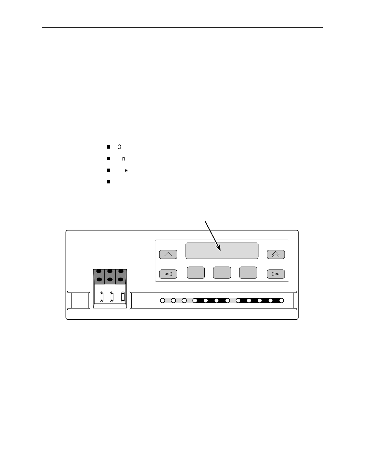
Standalone CSU Front Panel
The standalone CSU front panel contains:
One 2-line, 16-alphanumeric-character-per-line liquid crystal display (LCD)
One 7-button keypad (three Function and four directional keys)
Twelve light-emitting diodes (LEDs)
Six test jacks
The front panel is shown in Figure 1-1, 3150 CSU Front Panel.
LCD
ACCULINK
and the
COMSPHERE
.
ACCULINK
3150
NET MON EQPT
In
OutInOutInOut
OK
FAIL TEST SIG OOF ALRM
Figure 1-1. 3150 CSU Front Panel
F1 F2 F3
EER SIG ALRM PDVOOF BPV
NETWORK
DTE
496-14938
3150-A2-GB24-10 March 2001
1-3
1. Introduction
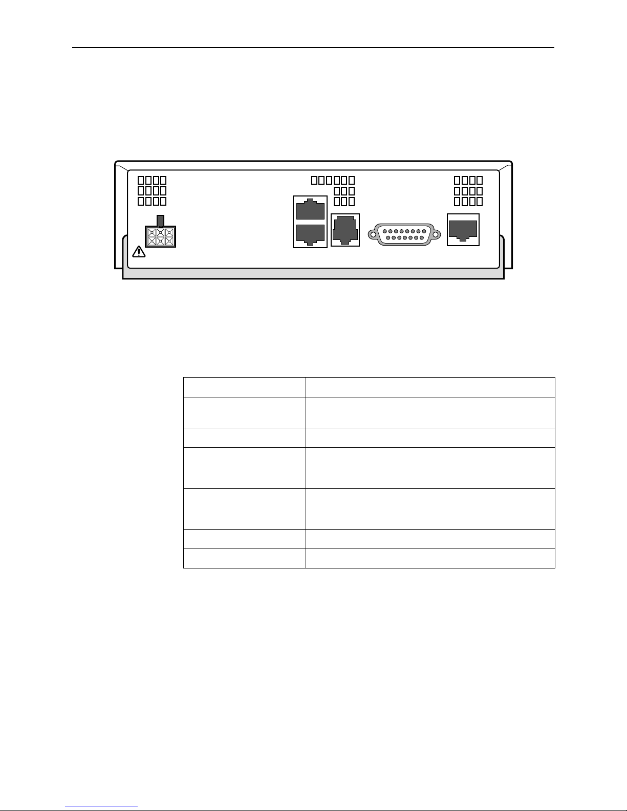
Standalone CSU Rear Panel
The standalone CSU rear panel contains the connectors required for the operation
of the CSU (Figure 1-2, 3150 CSU Rear Panel). The connectors and their
functions are listed in Table 1-1, Standalone CSU Rear Panel Connectors.
10 BASE-T
POWER
COM DSX-1MODEM NETWORK
99-14538-01
Figure 1-2. 3150 CSU Rear Panel
Tab le 1-1 . Sta ndalone CSU Rear Panel Connectors
Name Function
POWER Supplies power to the CSU by providing an attachment for
the ac power module.
10 BASE-T Supports a 10BaseT Ethernet connection.
COM Provides access to a locally connected PC, ASCII terminal
or printer, SNMP management link, or async terminal
interface.
MODEM Provides a connection to the integral modem for access to
a remotely connected PC, ASCII term inal or printer, SNMP
management link, or async terminal interface.
DSX-1 Provides access to the T1 DTE interface.
NETWORK Provides access to the T1 network.
March 2001 3150-A2-GB24-10
1-4
Installation
Overview
2
This chapter contains information for installing your standalone CSU. It includes
application examples, cabling, and power-on information.
NOTE:
Installation instructions for the carrier-mounted CSU are located in the
ACCULINK 3151 CSU and 3161 DSU/CSU General Information Guide
COMSPHERE 3000 Series Carrier Installation Manual
the
.
and
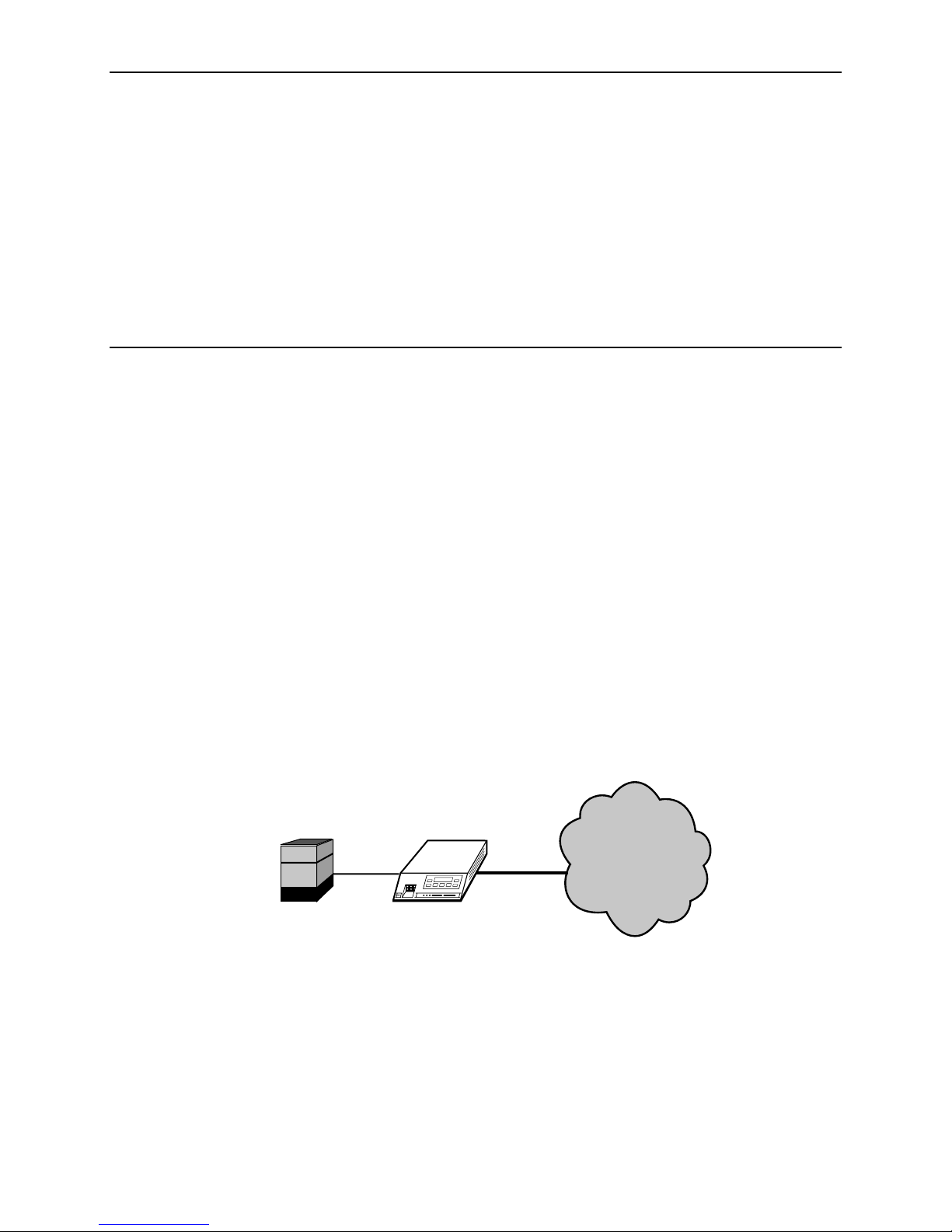
Application Example
The CSU acts as an interface between the T1 digital network and the customer’s
equipment. Figure 2-1, Application Example, shows an example of a CSU
application.
The CSU is connected to the customer’s equipment through the DTE interface. It
is connected to the T1 digital network through the network interface.
PBX
Figure 2-1. Application Example
NETWORK
CSU
496-14821-02
3150-A2-GB24-10 March 2001
2-1
2. Installation
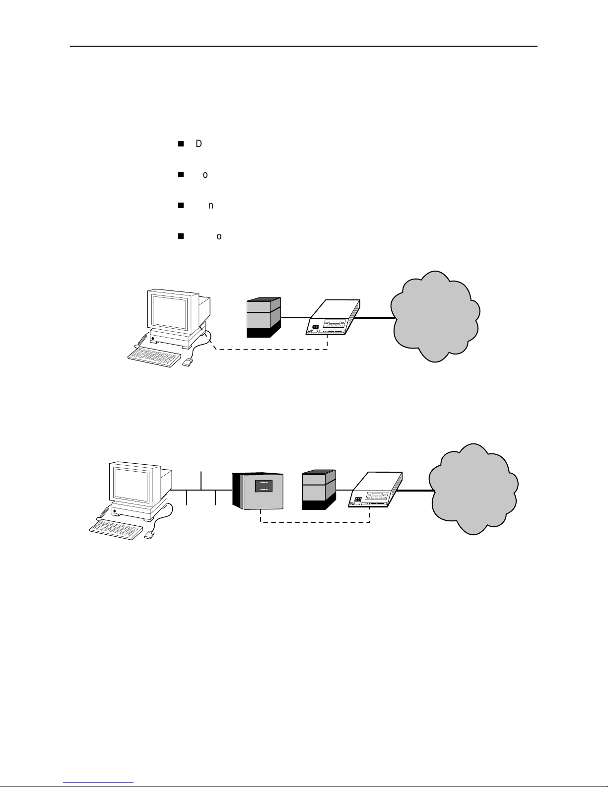
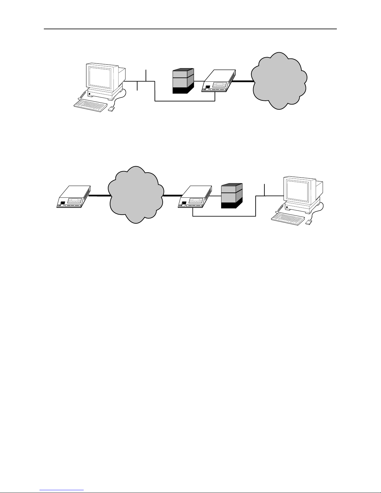
SNMP or Telnet Connection Examples
The CSU can be connected to an SNMP or Telnet system in a number of ways.
Some examples include:
Directly connecting the COM port to the SNMP or Telnet device
(Figure 2-2, D ir ect Connec tion).
Connecting the COM port to a network device (e.g., a router)
(Figure 2-3, Connection through a Router).
Connecting to an Ethernet LAN through the 10BaseT port
(Figure 2-4, Connection to a LAN).
Remotely accessing the CSU through the Facility Data Link (FDL)
(Figure 2-5, Remote Access through FDL).
PBX
PPP/SLIP
CSU
Figure 2-2. Direct Connection
ETHERNET
LAN
ROUTER
PPP/SLIP
Figure 2-3. Connection through a Router
NETWORK
496-14822-02
CSUPBX
NETWORK
496-14823-02
March 2001 3150-A2-GB24-10
2-2
2. Installation
ETHERNET
Figure 2-4. Connection to a LAN
NETWORK
FDL
PBX
PBX
CSU
NETWORK
99-14824-03
CSUCSU
PBX
ETHERNET
99-14826-03
Figure 2-5. Remote Access through FDL
3150-A2-GB24-10 March 2001
2-3

2. Installation
Important Instructions
Read and follow all warning notices and instructions marked on the CSU or
included in this guide.
For a complete listing of the safety instructions, see the
Instructions
496-15104
Installation Steps
Procedure
Import ant Safety
at the beginning of this guide.
HANDLING PRECAUTIONS FOR
!
STATIC-SENSITIVE DEVICES
This product is designed to pro tect sensitive components from damage
due to electrostatic discharge (ESD) during normal operation. When
performing installation procedures, however, take proper static control
precautions to prevent damage to equipment. If you are not sure of the
proper static control precautions, contact your nearest sales or service
representative.
1. Attach the power cord to the rear of the CSU and the other end to a grounded
115 Vac power outlet.
2. Attach the DTE cable (DB15) to the DTE connector on the CSU rear panel.
Then, connect the other end of the cable to the DTE.
3. Attach the 8-pin network cable to the NETWORK connector on the CSU rear
panel. Connect the other end of the cable to the RJ48C jack provided by the
telephone company.
4. If you intend to use front panel emulation or the asynchronous terminal
interface, connect a serial cable from your PC or terminal to the COM port on
the rear panel of the CSU.
5. If you intend to manage the 3150 CSU with SNMP over an Ethernet LAN,
connect the 10BaseT port to your LAN and assign an IP address to the port.
Configuring the 10BaseT Port
See
6. Power on the CSU to perform the power-on self-test.
7. During the power-on self-test, the
When the test is complete, verify that the CSU is functional by observing that
OK, NETWORK SIG
the
8. Set configuration options as required for your environment. See
Configuration Options
March 2001 3150-A2-GB24-10
2-4
, and
in Chapter 4,
in Chapter 4,
FAIL
DTE SIG
Configuration
LED flashes, then all LEDs blink twice.
LEDs are lit.
Configuration
.
.
Changing
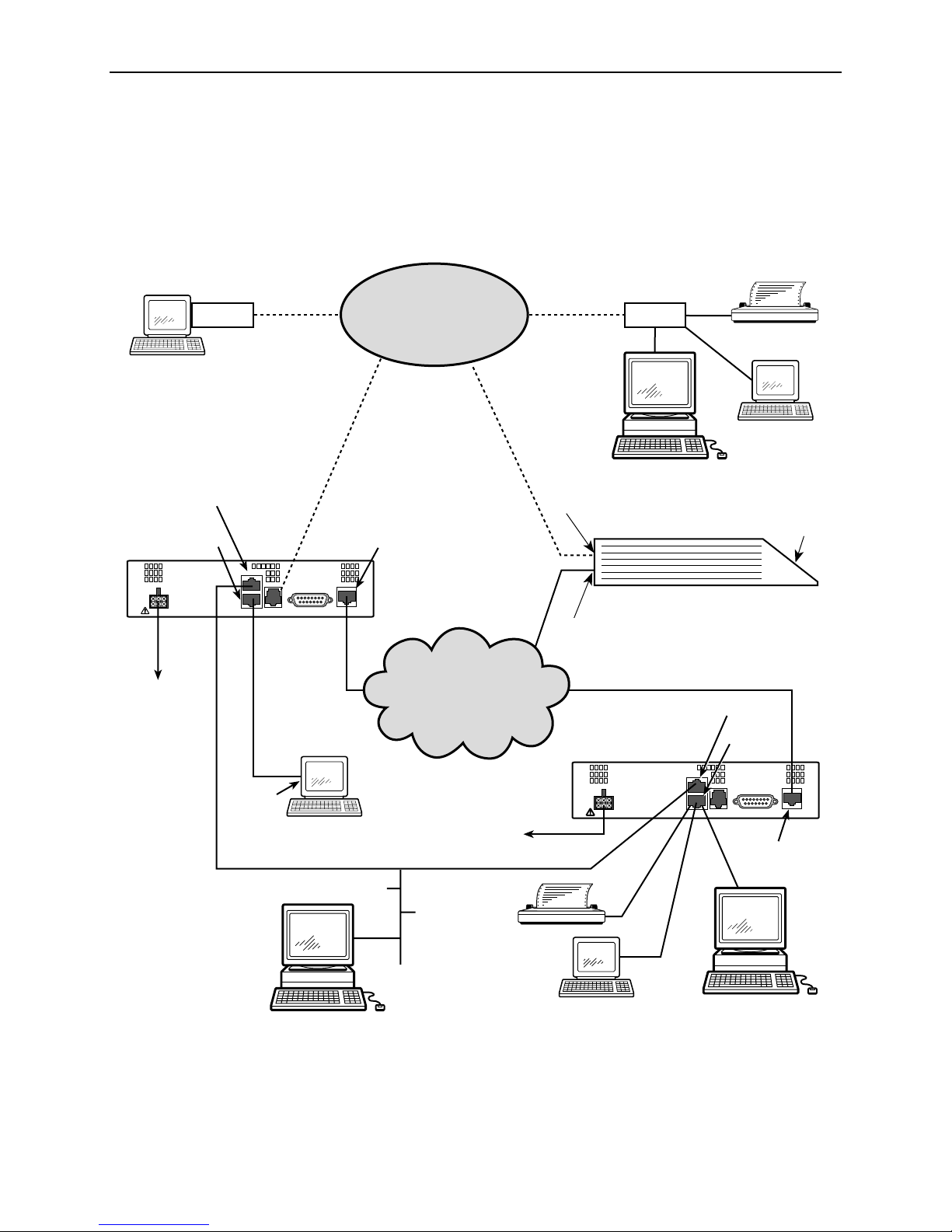
Cabling Examples
The CSU is supplied with an ac power module and a VF cable for the integral
modem. Optional cables are described in Appendix E,
Figure 2-6, Cabling Examples, illustrates some cabling options.
Pin Assignments
2. Installation
.
TERMINAL
POWER
POWER
MODEM
10 Base-T
Port
COM
PORT
MODEM
PORT
10 BASE-T
COM DSX-1MODEM NETWORK
SERIAL
PORT
NETWORK
PORT
3150
CSU
PSTN
T1 NETWORK
POWER
10BaseT
MODEM
PORT
NETWORK
PORT
3150
CSU
MODEM
OR
SNMP MANAGER
3150 CSU
POWER
OR
OR
PC
10 Base-T
Port
COM
PORT
10 BASE-T
COM DSX-1MODEM NETWORK
OR
NETWORK
PORT
FRONT
PANEL
SNMP MANAGER
Figure 2-6. Cabling Examples
3150-A2-GB24-10 March 2001
TERMINAL
SNMP MANAGER
99-14934-01
2-5
2. Installation
Power-On Self-Test
After you connect the CSU to a power source, the unit performs the power-on
self-test to ensure that it is in good working order. The CSU performs this test on
itself upon power-on or after a device reset, unless it has been disabled by the
Self-Test configuration option (see Appendix C,
The self-test includes a basic processor test, a limited memory test, a code
checksum test, and basic verification tests of the internal components. The front
panel LCD displays the progress and pass/fail status of these power-on tests.
Procedure
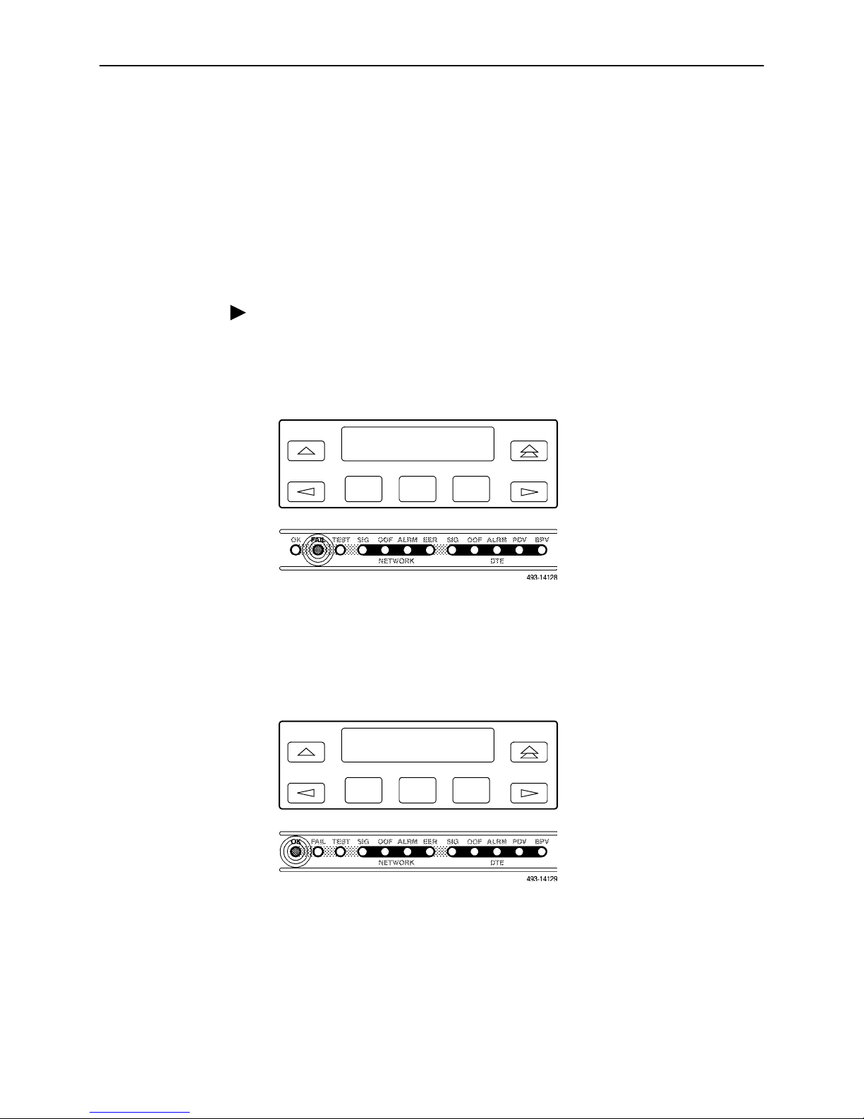
The power-on self-test consists of t he following steps:
1. Once the CSU is plugged in, the In Progress screen appears and the Fail LED
blinks ON and Off continuously.
Self-Test:
In Progress
Configuration Options
).
F1
F2
F3
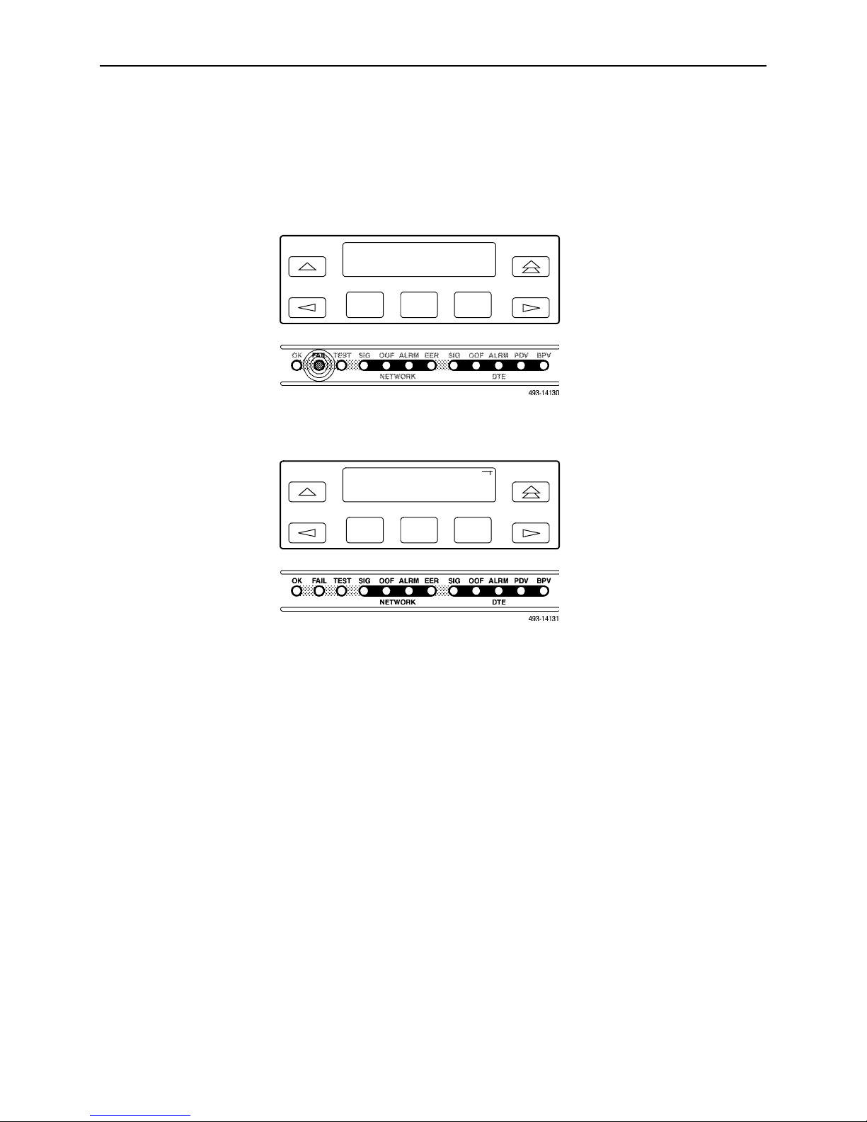
2. All the LEDs then start to flash simultaneously in the pattern twice ON, then
Off. Then, the LCD begins to flash characters and numbers in the same
pattern, alternating with the flashing LEDs.
3. If the self-test is successful, the Passed screen appears for one second, the
Fail LED turns Off and the OK LED lights.
Self-Test:
Passed
F1
F2
F3
March 2001 3150-A2-GB24-10
2-6
2. Installation
If the self-test fails, the Failed screen appears for five seconds. The Fail LED
lights, and an 8-digit failure code (
xxxxxxxx
) is displayed for use by service
personnel to determine the cause of the self-test failure. The CSU continues to
try to operate. If you are in doubt about the results of the self-test, use the
Self-Test Health command to display the status of this test (see
Health Messages
Self-Test:
Failed
in Chapter 7,
xxxxxxxx
Monitoring and Troubleshooting
Self-Test
).
F1
F2 F3
4. The top-level menu screen appears.
CSU ESF
Stat Test Cnfig
F1
F2 F3
3150-A2-GB24-10 March 2001
2-7

2. Installation
March 2001 3150-A2-GB24-10
2-8

Using the Front Panel
Overview
This chapter shows how to use:
The standalone CSU front panel and 3000 Series Carrier control panel to:
— Dis pl ay unit identity
— Reset the C SU
The front panel LEDs to:
— Mo nito r the status of the CSU
3
Front Panel
— Mo nito r the stat us of the networ k
— Mo nito r the status of the DTE
NOTE:
Additional information for the carrier-mounted CSU is located in the
ACCULINK 3151 CSU and 3161 DSU/CSU General Information Guide
COMSPHERE 3000 Series Carrier Installation Manual
the
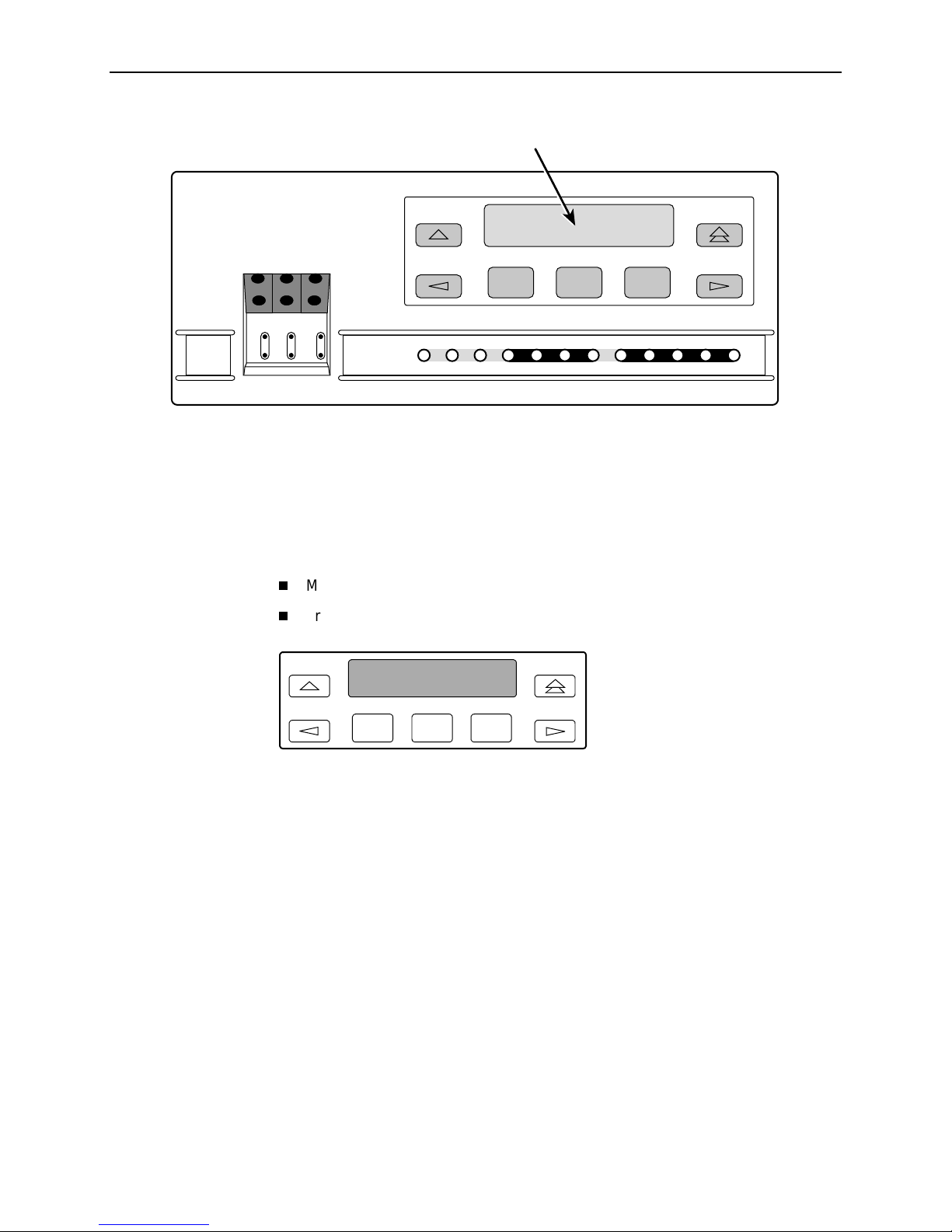
The standalone CSU front panel (Figure 3-1, Standalone CSU Front Panel)
consists of an LCD, a keypad, test jacks, and 12 LEDs. The carrier-mounted CSU
faceplate contains test jacks and 12 LEDs, however, the LCD and keypad are
located on the Shared Diagnostic Control Panel (SDCP) of the 3000 Series
Carrier. For more information about the SDCP, refer to the
Series Carrier Installation Manual
NOTE:
You can display a graphical representation of the CSU front panel on an
attached PC (see Appendix H,
.
Front Panel Emulation
.
COMSPHERE 3000
).
and
3150-A2-GB24-10 March 2001
3-1
3. Using the Front Panel
ACCULINK
3150
OutInOutInOut
NET MON EQPT
In
OK
FAIL TEST SIG OOF ALRM
Figure 3-1. Standalone CSU Front Panel
LCD
F1 F2 F3
EER SIG ALRM PDVOOF BPV
NETWORK
DTE
496-14938
LCD
The LCD (Figure 3-2, LCD) displays two types of data:
Messages such as alarms, command/test completion, and action in progress
Front panel menu tree information (see Appendix A,
Front Panel Menu
)
F1
F2
F3
Figure 3-2. LCD
The LCD displays status messages as requested via the Device Health and Status
branch of the front panel menu (see
Chapter 7,
Monitoring and Troubleshooting
Device Health and Status Messages
). In addition, the highest level status
in
message appears on the front panel automatically if no front panel action has
occurred at the CSU for the past five minutes.
The LCD also lists commands, configuration options, and test results. In most
cases, the top line shows the command or option name and default value, while
the second line displays options and responses. When a response is required,
select from the options displayed directly above the Function keys (F1, F2, F3);
make your choice by pressing the corresponding Function key.
March 2001 3150-A2-GB24-10
3-2
 Loading...