

Page 1
ACCULINK® 3172 and 3174
E1 DSU/CSU
Quick Reference
Document No. 3170-A2-GL10-10
Page 2

Copyright © 2001 Paradyne Corporation.
All rights reserved.
Printed in U.S.A.
Warranty, Sales, Service, and Training Information
Contact your local sales representative, service representative, or distributor directly for
any help needed. For additional information concerning warranty, sales, service, repair,
installation, documentation, training, distributor locations, or Paradyne worldwide office
locations , use one of the f ol lowing methods:
Internet:
to register your warranty at
Telephone:
speak with a compan y repre se nta tive.
— Within the U.S.A., call 1-800-870-2221
— Outside the U.S.A., call 1-727-530-2340
Visit the P aradyne W orld Wide W eb site at
www.paradyne.com/warranty
Call our automated system to receive current information by fax or to
www.paradyne.com
.)
. (Be sure
Document Feedback
We w elcome your comment s and sug gestions about thi s docum ent. Please mail the m to
Technical Publications, Paradyne Corporation, 8545 126th Ave. N., Largo, FL 33773, or
send e-mail to
in your correspondence. Please include your name and phone number if you are willing
to provide additional information.
. Include the number an d title of th is doc ument
Trademarks
ACCULINK is a registered trademark of Paradyne Corporation. All other products and
services mentioned h erein are the tr ademarks , service marks, reg istered tr adema rks, or
registered service marks of their respective owners.
Page 3

ACCULINK® 3172 and 3174 E1 DSU/CSU
Quick Reference
Document Number 3170-A2-GL10-10
July 2001
Product Documentation Online
Complete documentation for this product is available at
Select
Select the following document:
To request a paper copy of a Paradyne document:
Before installing the DSU/CSU , re ad the
to ensure com plianc e with e missio ns require ments , insta ll ferrite chokes as described i n
Quick Sta rt Procedure
Library → Technical Manuals → T1/E1 Digital Access Devices.
3170-A2-GB20
ACCULINK 3172 and 3174 E1 DSU/CSU Operator’s Guide
Within the U.S.A., call 1-800-PARADYNE (1-800-727-2396)
Outside the U.S.A., call 1-727-530-8623
Important Safety Instructions
on page 2.
www.paradyne.com
on page 16. Also,
.
1
Page 4
Quick Start Procedure
The following procedure is for experienced DSU/CSU users who are familiar with the
317x DSU/CSU installation process and have no special requirements for their
application. See the
Operator’s Guide
Procedure
The DSU/CSU is shipped with a power cable appropriate to the country of
1.
installation. Attach the power module cord to the rear of the DSU/ CSU and the other
end to a grounded AC power outlet. If you intend instead to use a 24 or –48 VDC
power supply, see the Operato r’s Guide.
Attach the DSU/CSU network connection to the E1 network using the appropriate
2.
cable. Attach the DSU/CSU to the customer premises equipment via the DTE and
port connectors.
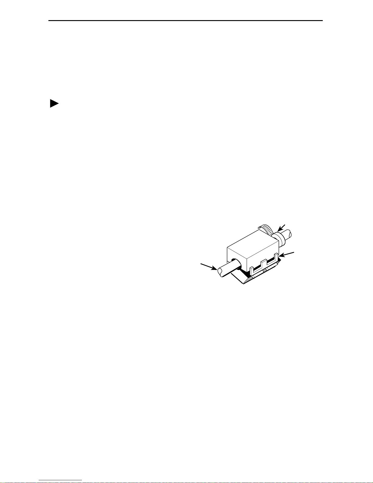
Install ferrite chok es o n cables attached to Ports 1 and 2 (Mo del 3172) or Ports 1–4
3.
(Model 3174):
— Pull up on the latch to open
the ferrite choke.
— Place the ferrite choke on the
cable as close to the
DSU/CSU as possible.
— Close the choke around the
cable and press down on the
latch to fasten it.
— Secure the chok e with a ca b le
tie.
ACCULINK 317x E1 Data Service Unit/Channel Service Unit
for more inf o rmation.
Ferrite Choke
Connector
End
Tie
Wrap
Plastic
Latch
97-14820-02
If you intend to use front panel emulation, connect the cable from the PC to the
4.
COM port on the rear panel of the DSU/CSU.
Power on the DSU/CSU to perform the power-up self-test.
5.
During the power-up self-test, the
6.
When the test is complete, verify that the DSU/CSU is functional by observing that
the OK,
If you intend to manage the DSU/CSU with SNMP, cable either the COM or AUX
7.
port (as appropriate for your configuration). Then, configure the SNMP
management link.
If you do not intend to use the DTE Drop/Insert E1 port, disable it using the
8.
configuration procedures in
Guide. (The default setting for this port is
Configure the ports and channels you intend to use and assign channels to the
9.
network interface.
NETWORK SIG
, and
Operation
FAIL
DTE SIG
LED flashes, then all LEDs blink twice.
LEDs are lit.
and
Configuration Options
Enabled
2
.)
of the Operator’s
Page 5

Cabling Examples
The DSU/CSU is supplied with an AC power mo dule. You must provide the DTE and
network cables.
Optional cables that yo u c an o rder f r om the c om pa n y are d es cribed in
Pin Assignments
in the Operator’s Guide.
NOTE:
The 120Ω/75Ω s witc h sele cts ei ther the 1 20-ohm balan ced net wo rk interf ac e or the
75-ohm unbalanced network interface. The RX SHIELD switch selects either an
“open” or “earth” shield connection for the 75-ohm RX interface. (This switch must
be set to “open” when using the 120-ohm interface.)
COM PORT
AUX
PORT
COM
PORT
POWER
CAUTION: AUX PORT OR COM PORT MUST NOT BE
CONNECTED TO PSTN OR E1 NETWORK
3100-F1-550
NETWORK
DTE
PORT 1 PORT 2CLOCK IN
SERIAL
PORT
120ý
NETWORK
TX
RX SHIELD
120ý
OPEN
EARTH
75ý
75ý
DSU/CSU
RX
75ý
NETWORK
NETWORK
FRONT
PANEL
DSU/CSU
TO AC
POWER
MODULE
NOTE:
3100 SERIES
FRONT PANEL
EMULATION
SOFTWARE,
3100-C1-010
MANAGER
TO DC
POWER
(OPTIONAL)
SNMP
COM PORT
POWER
CAUTION: AUX PORT OR COM PORT MUST NOT BE
CONNECTED TO PSTN OR E1 NETWORK
3100-F1-520
AUX
PORT
OR
COM
PORT
DTE
PORT 3 PORT 4
PORT 1 PORT 2CLOCK IN
3100-F1-540
NETWORK
NETWORK
TX
120ý
75ý
DSU/CSU
RX
RX SHIELD
120ý
OPEN
EARTH
75ý
75ý
98-14673a
3
Page 6
Configuration Options
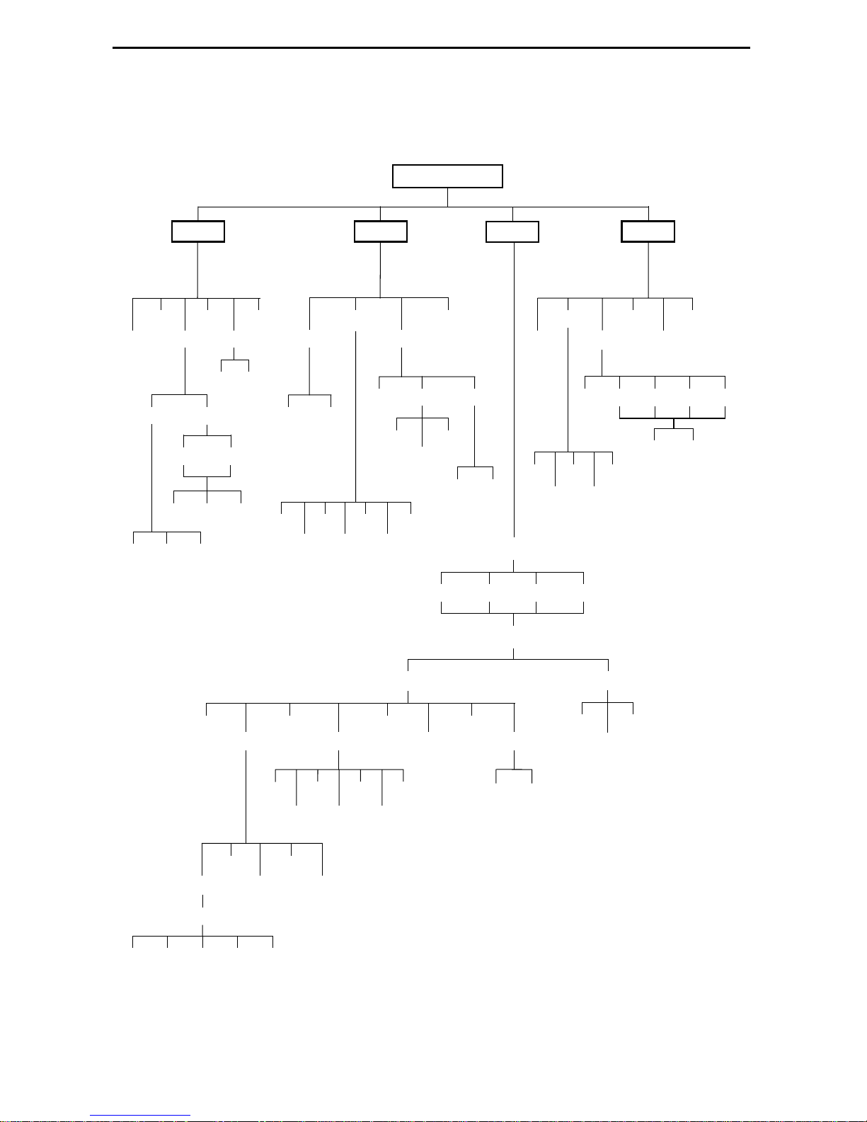
Configuration options are accessed from the Cnfig branch of the front panel menu.
DSU E1 CEPT
Stat
STest
DevHs
Cur 24Tot Intvl
Perf
NET
Cur 8Tot Intvl
TStat
E1 Prt
Prt
n
FarNear
LED
ID
Rlpbk
n
DCLBUPDCLB
Abort
LLB
DN
PLB
Lpbk
DLB
Test
Abort
RLB
DCLB
Cnfig
Lamp
Ptrns
Send
511
1in8
DTLB
Mon
QRSS
QRSS 511
Load Edit Area From:
Activ Cust1 Cust2 Fact
Choose Function:
LED
Rel ClrReg
NET Prt1 Prt2 Prt3 Prt4
DTE
Prt2
Prt4
Prt1
Prt3
Ctrl
Reset
DL
CID
FarNear
Port Chan
Dsply
Prt1
Copy
Port Select :
All Prt1 Prt2 Prt3 Prt4
Prt2
NETDTE
Clear
Prt3
DTE
Prt4
Prt1
Prt2
Gen
Prt3
Edit
Prt4
User
Alarm
SNMP
Gen Trap
Save
Activ Cust2
Cust1
98-14606a
4
Page 7

Factory default configuration options are shown in
boldface
type in the following tables.
Table 1. DTE Interface Configuration Options
Option Factory Comments/Description
DTE Port:
DTE Frame: CRC4 Selects framing format.
DTE Coding: AMI Selects line coding format.
Extrn DLB:
(External DTE
Loopback)
Send Ones:
Enab
Disab
noCRC
HDB3
Enab Allows control of DLB on external contact
Disab
Enab
Disab
Enables the use of the DTE Drop/Insert port.
closure.
Sends all ones on channels allocated to the
network E1 on LOS, LOF, or AIS.
Table 2. Port Configuration Options (1 of 3)
Option Factory Comments/Description
Po rt Type:
Base Rate:
Net DCLB: Enab Network-initiated DCLB, allows DCLB to be
E530
V.35
RS449
X.21
Nx64
Nx56
Disab
Selects the port type: EIA-530A, V.35, RS449,
or X.21.
Enables the port to either Nx56 or Nx64 rates.
controlled by inband V.54 codes.
5
Page 8

Table 2. Port Configuration Options (2 of 3)
Option Factory Comments/Description
Po rt LB:
Disab
Port-initiated Loopbacks, allows Loopbacks to
be initiated through the port by the external
DTLB
DTE.
DCLB
Both
All Ones: Disab All ones sent to network (DTE) E1 when DTR
or RTS interrupted.
DTR
RTS
Both
Rcv RAI:
(Action on Re ceived
Remote Alarm
None Data port remains enabled, or is disabled, on
receiving RAI on the network interface.
Halt
Indication)
Tx Clock:
Int
Selects whether the transmitted data clock is
internal (TXC) or external (XTXC).
Ext
InvertTxC:
(Invert Tx Clock)
Enab Selects phase inversion of the transmit clock
(TXC).
Disab
InvertData: Enab Allows the data on the port to be inverted.
Disab
EDL: Enab Specifies whether the Embedded Data Link is
enabled.
Disab
Err Rate:
(Excessive Error
Rate)
10E-4
10E-5
Selects the error rate threshold f or Exces si ve
Error Rate Alarm.
10E-6
10E-7
10E-8
10E-9
6
Page 9

Table 2. Port Configuration Options (3 of 3)
Option Factory Comments/Description
Near-end:
Far-end:
Mgmt Link: Enab Specifies whether the EDL Ma nagement Link is
Disab
Maint
Send
Both
Disab
Maint
Disab
Specifi es whether the device will maintain
near-end performance statistics.
Specifi es whether the device will maintain
far-end performance statistics.
enabled.
Table 3. Network Interface Configuration Options
Option Factory Comments/Description
NET Frame: CRC4 Selects framing format.
noCRC
Mgmt Link:
Circuit Ident: Edit Specifies the transmission vendor’s circuit
Disab
SNMP
Clear
Specifies whether the FDL’s Management Link
is enabled.
identifier.
7
Page 10

Table 4. DTE Cha nnel Configuration Options
Option Factory Comments/Description
DTE Channels: TS16 Selects TS16 for signaling or
assigns DS0 chan nels on the
Assign
TS16: Data Specifies whether time
Rsvd
DTE Drop/Insert interface to
DS0 channels on the
network interface.
slot 16 is reserved for
signaling information or
available for data.
Line 2
Line 1 Displays:
Displays: Meaning Comments/Description
N1 N2 N3 ......
N24:
—
D1, D2 ... D24 Channel
Prt1
Prt2
Prt3
Prt4
Unassigned
assigned to this
DTE channel
Channel
assigned t o port
1, 2, 3, or 4
Function key under the
channel (N1, N2, etc.)
selects the DTE channel to
assign (D1 through D24,
or –).
8
Page 11

Tab l e 5. Data Port Channel Configurati on Options (1 of 2)
Option Factory Comments/Description
Assign To:
NET
DTE
Prt
n
Assign By:
Block
Chan
Port Rate: 64 (56)
128 (112)
192 (168)
256 (224)
320 (280)
384 (336)
448 (392)
512 (448)
576 (504)
640 (560)
704 (616)
768 (672)
832 (728)
896 (784)
960 (840)
1024 (896)
1088 (952)
1152 (1008)
1216 (1064)
1280 (1120)
1344 (1176)
1408 (1232)
1472 (1288)
1536 (1344)
1600 (1400)
1664 (1456)
1728 (1512)
1792 (1568)
1856 (1624)
1920 (1680)
1984 (1736)
Assigns this port to channels on the Network
or DTE Drop/Insert interface, or to another
port.
Determines how channels are assigned:
contiguous blocks or individual channels.
Selects the data rate f or the port.
The possible rates depend on whether the
port is configured for Nx56 or Nx64.
This configuration option only appears if the
“Assigned By” configuration option is Block.
NOTE:
Configuration options in this table are made available after Prt
or 2 for the Model 3172 and 1, 2, 3, or 4 for the Model 3174) is selected from the
Channel Config screen.
n
(where n is 1
9
Page 12

Tab l e 5. Data Port Channel Configurati on Options (2 of 2)
Option Factory Comments/Description
Start At: Clear Clears (unassigns) channels for this port.
N1 (D1)
N2 (D2)
N3 (D3)
•
•
•
N31 (D31)
This configuration option appears if the
“Assigned By” config urat ion option is Bloc k or
ACAMI.
Line 2
Line 1 Displays:
N1 N2 N3... N31:
(If assigned to NET)
D1 D2 D3... D31:
(If assigned to DTE)
NOTE:
or 2 for the Model 3172 and 1, 2, 3, or 4 for the Model 3174) is selected from the
Channel Config screen.
Configuration options in this table are made available after Prt
Displays: Comments/Description
— This configuration option appears if the
“Assigned By” configuration option is
Prt1, Prt2,
Prt3, Prt4
D1, D2... D31
N1, N2... N31
individual chann els (Cha n).
Function key under the channel (N1, N2 etc.)
assigns (unassig ns) port (1, 2, 3, or 4) to that
channel.
n
(where n is 1
10
Page 13

Table 6. General Configuration Options
Option Factory Comments/Description
Pri Clk Src:
Sec Clk Src:
Clock Rate:
NET
DTE
n
Prt
Int
Ext
NET
DTE
n
Prt
Int
Ext
2048
8
Selects the primary clock source for the
DSU/CSU.
Selects the secondary clock source for the
DSU/CSU, used in the event of failure of the
primary source.
Selects the clock rate of the source if exter nal.
Table 7. User Configuration Options (1 of 2)
Option Factory Comments/Description
Self-Test:
Com Use: SNMP Controls how the COM port is used.
Com Type:
Com Clk:
Enab
Disab
ASCII
Daisy
Async
Sync
Int
Ext
Allows bypass of self-test on initialization.
Controls whether the CO M port is synchronous
or asynch ronous.
Controls whether the COM port uses an
internal or external clock.
11
Page 14

Table 7. User Configuration Options (2 of 2)
Option Factory Comments/Description
Com Rate:
1.2 Selects the bit rate for the COM port.
(Communication Port
Rate)
2.4
4.8
9.6
14.4
19.2
38.4
Char Length: 7 Selects the character length for the COM port.
8
CParity:
None
Selects the parity for the COM port.
(Communication Port
Parity)
Even
Odd
CStop Bits:
(Communication Port
Stop Bits)
1
1.5
Selects the number of stop bits for the COM
port.
2
Ignore DTR: Yes Specifies whether the COM port ignores DTR.
No
Aux Use:
None
Controls how the auxiliary port is used.
SNMP
Daisy
Aux Rate: 9.6 Configures the bit rate for the auxiliary por t.
14.4
19.2
38.4
12
Page 15

Table 8. Alarm Configuration Options
Option Factory 1 Comments/Descripti on
Alrm Msg: Enab Determines whether alarm messages are
routed to the ASCII terminal or printer att ac hed
Disab
SNMP Trap: Enab Sends SNMP traps.
Disab
to the COM port.
Table 9. General SNMP Configuration Options (1 of 2)
Option Factory Comments/Description
System Name: Edit The SNMP system name for this device.
Clear
System Location: Edit The SNMP system location for this device.
Clear
System Contact: Edit The SNMP system contact name for this
device.
Clear
CommunityName1: Edit A community name that is allowed access to
this device. Defaults to
Clear
Access 1:
CommunityName2: Edit A community name that is allowed access to
Access 2:
Read
R/W
Clear
Read
R/W
The type of access allowed for community
name 1.
this device.
The type of access allowed for community
name 2.
public
.
IP Adr: Edit The IP address needed to access the device.
NetMask: Edit The Subnet Mask needed to access the device.
Clear
Clear
13
Page 16

Table 9. General SNMP Configuration Options (2 of 2)
Option Factory Comments/Description
Com IP Adr: Edit The IP address for the COM port when the
COM port is co nfigured for SNMP.
Clear
Com NetMask: Edit The Subnet Mask needed to access t he device
when the COM port is configured for SNMP.
Clear
Com Link:
PPP
The link layer protocol for the COM port when
the COM port is configur ed for SNMP.
SLIP
Aux IP Adr: Edit Specifies the IP address of the AUX por t when
the AUX port is configured for SNMP.
Clear
Aux NetMask: Edit Specifies the Subnet Mask needed to access
the device when the AUX port is configured for
Def Netwk:
Clear
None
SNMP.
Specifies the default network destination.
Com
Aux
FDL
EDL
n
14
Page 17

Table 10 . SNMP Trap Configuration Options
Option Factory 1 Comments/Descripti on
Num Trap Mgrs:
1
2–6
n
IP Adr: Edit Specifies the IP address for each trap manager.
Trap
The number of trap managers su pported by the
device.
This configuration option is repeated for all
Trapn Dst:
Clear
None
n
managers.
Specifies the network destination for Trap
Manager n.
Com
Aux
FDL
n
EDL
Gen Trap: Disab Specifies the general trap types to enable:
WarmStart, Authentication Failure or both.
Warm
Auth
Both
Entp Trap:
Enab
Specifies whether the EnterpriseSpecific trap
type is enabled.
Disab
Link Trap: Disab Specifies the link trap type to enable: Trap on
Link Up, Link Down, or both.
Up
Down
Both
Trap I/F: NET When any li nk tr ap t ypes are e nab l ed, sp ecifie s
which links to send traps for.
DTE
E1s
Ports
All
15
Page 18

!
Important Safety Instructions
Read and follow all warning notices and instructions marked on the product or
1.
included in the manual.
This product is intended to be used with a 3-wire grounding type plug – a plug
2.
which has a grounding pin. This is a safety feature. Equipment grounding is vital to
ensure safe operation. Do not defeat the purpose of the grounding type plug by
modifying the plug or using an adapter.
Prior to installation, use an outlet tester or a voltmeter to check the AC receptacle
for the presence of earth ground. If the receptacle is not properly grounded, the
installation must not continue unti l a qua lif ied electrician has corrected the problem.
If a 3-wire grounding type power source is not available, consult a qualified
electrician to determine another method of grounding the equipment.
Slots and openings in the cabinet are provided for ventilation. To ensure reliable
3.
operation of the product and to protect it from overheating, these slots and
openings must not be blocked or covered.
Do not allow anyth ing to rest on the po wer cord a nd do not lo cate the pro duct wher e
4.
persons will walk on the power cord.
Do not attemp t to s ervice thi s p roduct your se lf, as openi ng or re moving covers may
5.
expose you to dangerous high voltage points or other risks. Refer all servicing to
qualified service personnel.
General purpose cables are provided with this product. Special cables, which may
6.
be required by the regulatory inspection authority for the installation site, are the
responsibility of the customer.
When installed in the final configuration, the product must comply with the
7.
applicable Safety Standards and regulatory requirements of the country in which it
is installed. If necessary, consult with the appropriate regulatory agencies and
inspection authorities to ensure compliance.
A rare phenomenon can create a voltage potential between the earth grounds of
8.
two or more bu ildings. If products installed in separate buildings are
interconnected
qualified electrical consultant to determine whether or not this phenomenon exists
and, if necessary, implement corrective action prior to interconnecting the products.
Input pow er to t he AC voltage configurati on of this prod uct m ust be pr ovid ed b y on e
9.
of the following: (1) a UL Listed/CSA certified power source with a Class 2 or
Limited Power Source (LPS) output for use in North America, or (2) a c ertified
power source with a Safety Extra Low Voltage (SELV) output for use in the country
of installation.
Input power to the DC voltage configurations of this product must be provided by
one of the following: (1) a National Electric Code (NEC)/Canadian Electric Code
(CEC) Class 2 circuit for use in North America, or (2) a certified Safety Extra Low
Voltage (SELV) circuit input for use in the country of installation.
, the volta ge p oten t ia l m ay cause a hazardous condition. Consult a
16
Page 19

In addition, if the equip ment is to be used with teleco mmuni cations circu its, tak e the
10.
following precautions:
— Never install telephone wiring during a lightning storm.
— Never install telephone jacks in wet locations unless the jack is specifically
designed for wet locations.
— Nev er tou ch uninsula ted teleph one wire s or terminals unless th e telepho ne line
has been disconnected at the network interface.
— Use caution when installing or modifying telephone lines.
— Av oid u sing a teleph one (other than a co rdless type ) during a n ele ctrical storm.
There may be a remote risk of electric shock from lightning.
— Do not use the telephone to report a gas leak in the vicinity of the leak.
EMI Notices
!
UNITED STATES – EMI NOTICE:
This equipment has been tested and found to comply with the limits for a
Class A digital device, pursuant to Part 15 of the FCC rules. These limits are
designed to pr o vide r eason able pro tecti on ag ainst har mful inte rfer ence whe n
the equipment is operated in a commercial environment. This equipment
generates, uses, and can radiate radio frequency energy and, if not installed
and used in accordance with the instruction manual, may cause harmful
interference to radio communications. Operation of this equipment in a
residential area is likely to cause harmful interference in which case the user
will be required to correct the interference at his own expense.
The authority to operate this equipment is conditioned by the requirements
that no modifications will be made to the equipment unless the changes or
modifications are expressly approved by Paradyne Corporation.
!
CANADA – EMI NOTICE:
This Class A digital apparatus meets all requirements of the Canadian
interference-causing equipment regulations.
Cet appareil numérique de la classe A respecte toutes les exigences du
règlement sur le matérial brouilleur du Canada.
17
Page 20

CE Marking
Models 3172-A1-410 and 3174-A1-410 of this product are marked with the CE mark.
This mark has been affixed to demonstrate full compliance with the following European
Directives:
Directive 73/23/E EC –
of the laws of the member states relating to electrical equipment designed for use
within certain voltage limits, as amended by Directive 93/68/EEC.
Directive 89/336/EEC
the laws of the member states relati ng to E lectro-M ag ne t ic Co mp ati bil ity (EMC ), as
amended by Directive 93/68/EEC
Directive 91/263/EEC
the laws of the member states concerning telecommunication terminal equipment,
including the mutual recognition of their conformity, as amended by Directive
93/68/EEC . The appli catio n of thi s dire ctiv e is in relati on onl y to n etwork c onnec tion
via the 120-ohm G.703 interface as specified in CTR12.
Council Directiv e of 19 Fe bruary 1973 on the harmonizati on
– Council Directive of 3 May 1989 on the approximation of
.
– Council Directive of 29 April 1991 on the approximation of
*3170-A2-GL10-10*
18
 Loading...