

Paradyne ACCULINK 3172, 3174, ACCULINK 3174 E1 CSU, ACCULINK 3172 E1 CSU Quick Reference

ACCULINK® 3172 and 3174
E1 DSU/CSU
Quick Reference
Document No. 3170-A2-GL10-10

Copyright © 2001 Paradyne Corporation.
All rights reserved.
Printed in U.S.A.
Warranty, Sales, Service, and Training Information
Contact your local sales representative, service representative, or distributor directly for
any help needed. For additional information concerning warranty, sales, service, repair,
installation, documentation, training, distributor locations, or Paradyne worldwide office
locations , use one of the f ol lowing methods:
Internet:
to register your warranty at
Telephone:
speak with a compan y repre se nta tive.
— Within the U.S.A., call 1-800-870-2221
— Outside the U.S.A., call 1-727-530-2340
Visit the P aradyne W orld Wide W eb site at
www.paradyne.com/warranty
Call our automated system to receive current information by fax or to
www.paradyne.com
.)
. (Be sure
Document Feedback
We w elcome your comment s and sug gestions about thi s docum ent. Please mail the m to
Technical Publications, Paradyne Corporation, 8545 126th Ave. N., Largo, FL 33773, or
send e-mail to
in your correspondence. Please include your name and phone number if you are willing
to provide additional information.
userdoc@paradyne.com
. Include the number an d title of th is doc ument
Trademarks
ACCULINK is a registered trademark of Paradyne Corporation. All other products and
services mentioned h erein are the tr ademarks , service marks, reg istered tr adema rks, or
registered service marks of their respective owners.

ACCULINK® 3172 and 3174 E1 DSU/CSU
Quick Reference
Document Number 3170-A2-GL10-10
July 2001
Product Documentation Online
Complete documentation for this product is available at
Select
Select the following document:
To request a paper copy of a Paradyne document:
Before installing the DSU/CSU , re ad the
to ensure com plianc e with e missio ns require ments , insta ll ferrite chokes as described i n
Quick Sta rt Procedure
Library → Technical Manuals → T1/E1 Digital Access Devices.
3170-A2-GB20
ACCULINK 3172 and 3174 E1 DSU/CSU Operator’s Guide
Within the U.S.A., call 1-800-PARADYNE (1-800-727-2396)
Outside the U.S.A., call 1-727-530-8623
Important Safety Instructions
on page 2.
www.paradyne.com
on page 16. Also,
.
1
Quick Start Procedure
The following procedure is for experienced DSU/CSU users who are familiar with the
317x DSU/CSU installation process and have no special requirements for their
application. See the
Operator’s Guide
Procedure
The DSU/CSU is shipped with a power cable appropriate to the country of
1.
installation. Attach the power module cord to the rear of the DSU/ CSU and the other
end to a grounded AC power outlet. If you intend instead to use a 24 or –48 VDC
power supply, see the Operato r’s Guide.
Attach the DSU/CSU network connection to the E1 network using the appropriate
2.
cable. Attach the DSU/CSU to the customer premises equipment via the DTE and
port connectors.
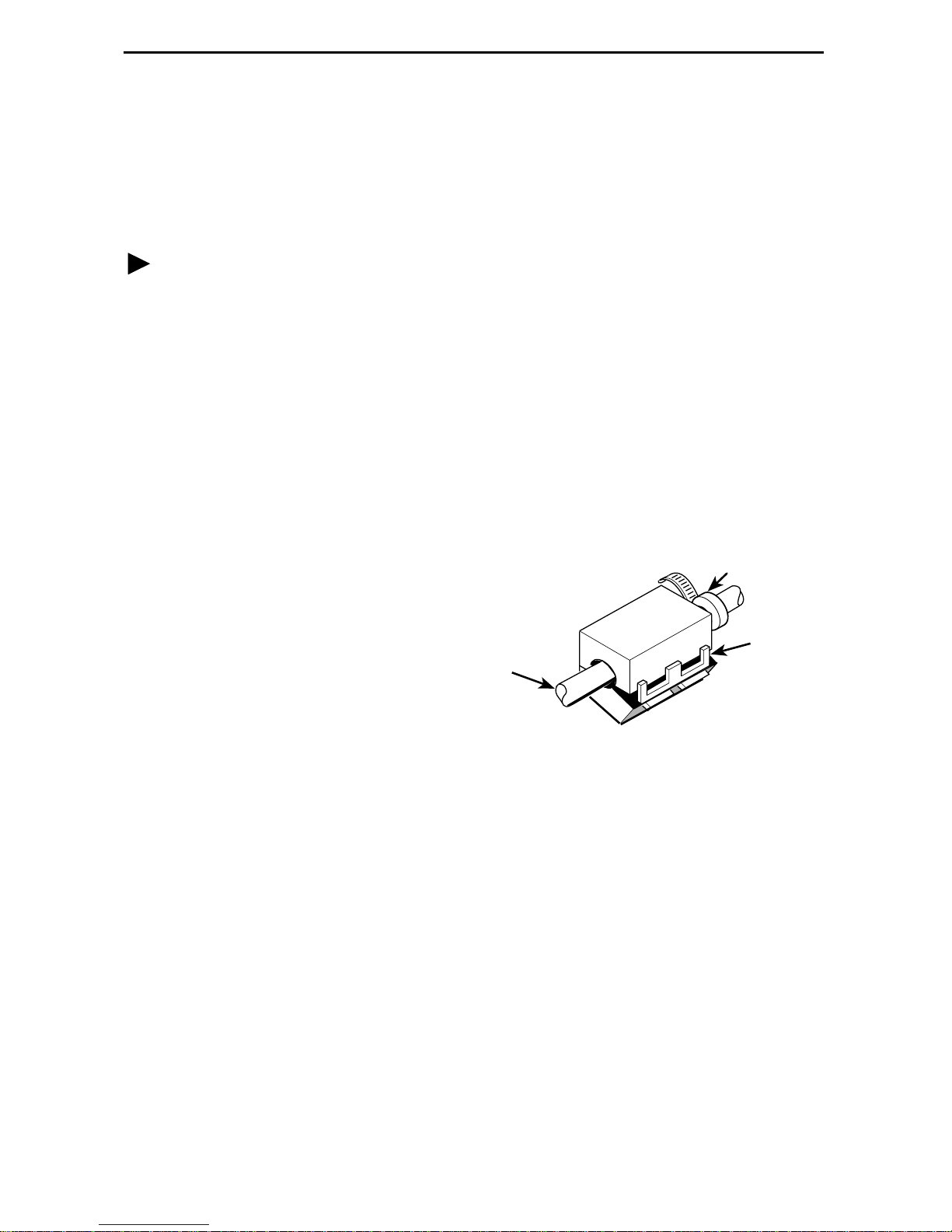
Install ferrite chok es o n cables attached to Ports 1 and 2 (Mo del 3172) or Ports 1–4
3.
(Model 3174):
— Pull up on the latch to open
the ferrite choke.
— Place the ferrite choke on the
cable as close to the
DSU/CSU as possible.
— Close the choke around the
cable and press down on the
latch to fasten it.
— Secure the chok e with a ca b le
tie.
ACCULINK 317x E1 Data Service Unit/Channel Service Unit
for more inf o rmation.
Ferrite Choke
Connector
End
Tie
Wrap
Plastic
Latch
97-14820-02
If you intend to use front panel emulation, connect the cable from the PC to the
4.
COM port on the rear panel of the DSU/CSU.
Power on the DSU/CSU to perform the power-up self-test.
5.
During the power-up self-test, the
6.
When the test is complete, verify that the DSU/CSU is functional by observing that
the OK,
If you intend to manage the DSU/CSU with SNMP, cable either the COM or AUX
7.
port (as appropriate for your configuration). Then, configure the SNMP
management link.
If you do not intend to use the DTE Drop/Insert E1 port, disable it using the
8.
configuration procedures in
Guide. (The default setting for this port is
Configure the ports and channels you intend to use and assign channels to the
9.
network interface.
NETWORK SIG
, and
Operation
FAIL
DTE SIG
LED flashes, then all LEDs blink twice.
LEDs are lit.
and
Configuration Options
Enabled
2
.)
of the Operator’s

Cabling Examples
The DSU/CSU is supplied with an AC power mo dule. You must provide the DTE and
network cables.
Optional cables that yo u c an o rder f r om the c om pa n y are d es cribed in
Pin Assignments
in the Operator’s Guide.
NOTE:
The 120Ω/75Ω s witc h sele cts ei ther the 1 20-ohm balan ced net wo rk interf ac e or the
75-ohm unbalanced network interface. The RX SHIELD switch selects either an
“open” or “earth” shield connection for the 75-ohm RX interface. (This switch must
be set to “open” when using the 120-ohm interface.)
COM PORT
AUX
PORT
COM
PORT
POWER
CAUTION: AUX PORT OR COM PORT MUST NOT BE
CONNECTED TO PSTN OR E1 NETWORK
3100-F1-550
NETWORK
DTE
PORT 1 PORT 2CLOCK IN
SERIAL
PORT
120ý
NETWORK
TX
RX SHIELD
120ý
OPEN
EARTH
75ý
75ý
DSU/CSU
RX
75ý
NETWORK
NETWORK
FRONT
PANEL
DSU/CSU
TO AC
POWER
MODULE
NOTE:
3100 SERIES
FRONT PANEL
EMULATION
SOFTWARE,
3100-C1-010
MANAGER
TO DC
POWER
(OPTIONAL)
SNMP
COM PORT
POWER
CAUTION: AUX PORT OR COM PORT MUST NOT BE
CONNECTED TO PSTN OR E1 NETWORK
3100-F1-520
AUX
PORT
OR
COM
PORT
DTE
PORT 3 PORT 4
PORT 1 PORT 2CLOCK IN
3100-F1-540
NETWORK
NETWORK
TX
120ý
75ý
DSU/CSU
RX
RX SHIELD
120ý
OPEN
EARTH
75ý
75ý
98-14673a
3
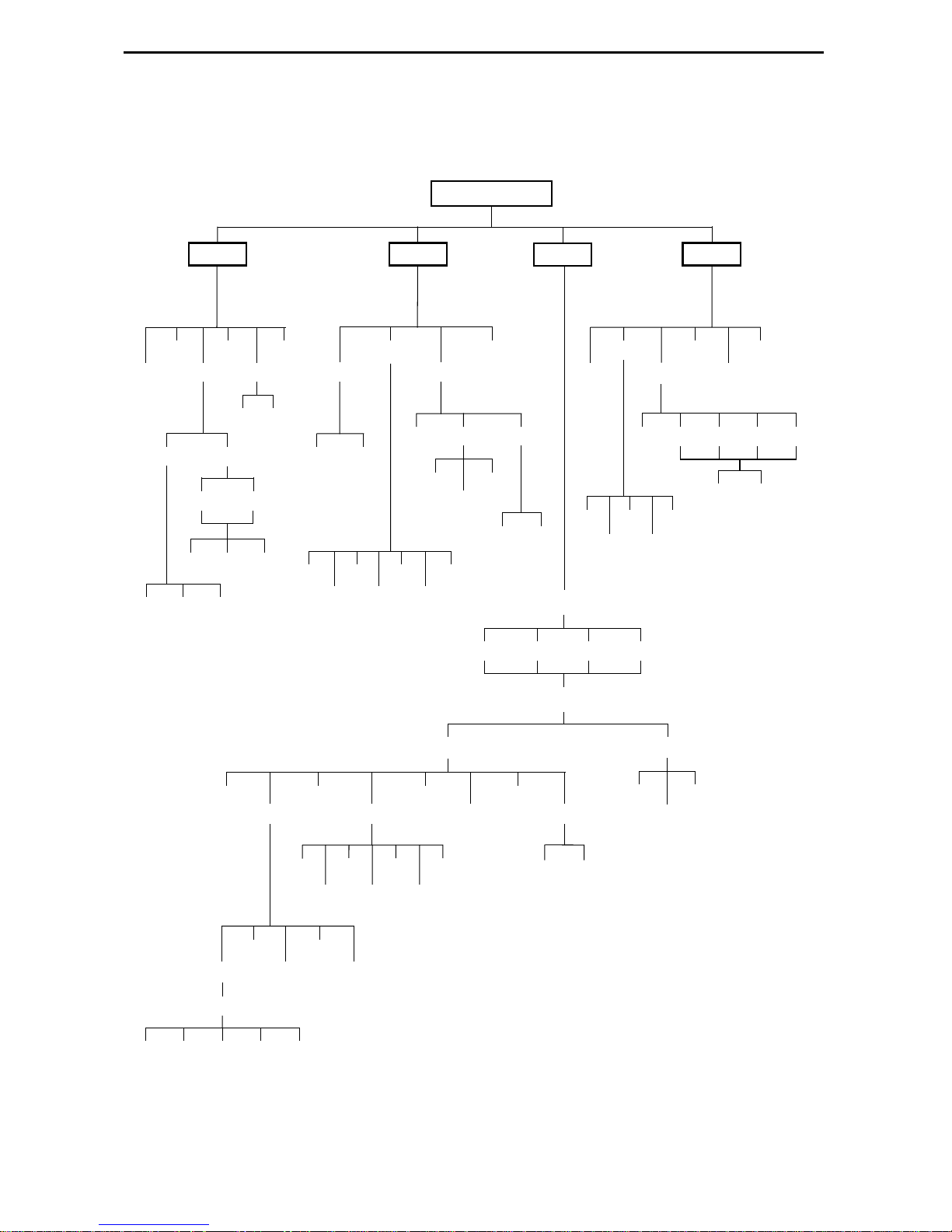
Configuration Options
Configuration options are accessed from the Cnfig branch of the front panel menu.
DSU E1 CEPT
Stat
STest
DevHs
Cur 24Tot Intvl
Perf
NET
Cur 8Tot Intvl
TStat
E1 Prt
Prt
n
FarNear
LED
ID
Rlpbk
n
DCLBUPDCLB
Abort
LLB
DN
PLB
Lpbk
DLB
Test
Abort
RLB
DCLB
Cnfig
Lamp
Ptrns
Send
511
1in8
DTLB
Mon
QRSS
QRSS 511
Load Edit Area From:
Activ Cust1 Cust2 Fact
Choose Function:
LED
Rel ClrReg
NET Prt1 Prt2 Prt3 Prt4
DTE
Prt2
Prt4
Prt1
Prt3
Ctrl
Reset
DL
CID
FarNear
Port Chan
Dsply
Prt1
Copy
Port Select :
All Prt1 Prt2 Prt3 Prt4
Prt2
NETDTE
Clear
Prt3
DTE
Prt4
Prt1
Prt2
Gen
Prt3
Edit
Prt4
User
Alarm
SNMP
Gen Trap
Save
Activ Cust2
Cust1
98-14606a
4
 Loading...