

Page 1

FrameSaver SLV
MODELS 9820, 9820-2M,
9820-8M, and 9820-45M
USER’S GUIDE
Document No. 9820-A2-GB20-20
June 2000
Page 2

Copyright E 2000 Paradyne Corporation.
All rights reserved.
Printed in U.S.A.
Notice
This publication is protected by federal copyright law. No part of this publication may be copied or distributed,
transmitted, transcribed, stored in a retrieval system, or translated into any human or computer language in any form
or by any means, electronic, mechanical, magnetic, manual or otherwise, or disclosed to third parties without the
express written permission of Paradyne Corporation, 8545 126th Ave. N., Largo, FL 33773.
Paradyne Corporation makes no representation or warranties with respect to the contents hereof and specifically
disclaims any implied warranties of merchantability or fitness for a particular purpose. Further, Paradyne Corporation
reserves the right to revise this publication and to make changes from time to time in the contents hereof without
obligation of Paradyne Corporation to notify any person of such revision or changes.
Changes and enhancements to the product and to the information herein will be documented and issued as a new
release to this manual.
Warranty, Sales, Service, and Training Information
Contact your local sales representative, service representative, or distributor directly for any help needed. For
additional information concerning warranty , sales, service, repair , installation, documentation, training, distributor
locations, or Paradyne worldwide office locations, use one of the following methods:
H Internet: Visit the Paradyne World Wide Web site at www.paradyne.com. (Be sure to register your warranty at
www.paradyne.com/warranty.)
H Telephone: Call our automated system to receive current information by fax or to speak with a company
representative.
— Within the U.S.A., call 1-800-870-2221
— Outside the U.S.A., call 1-727-530-2340
Document Feedback
We welcome your comments and suggestions about this document. Please mail them to Technical Publications,
Paradyne Corporation, 8545 126th Ave. N., Largo, FL 33773, or send e-mail to userdoc@paradyne.com. Include
the number and title of this document in your correspondence. Please include your name and phone number if you
are willing to provide additional clarification.
Trademarks
ACCULINK, COMSPHERE, FrameSaver, Hotwire, and NextEDGE are registered trademarks of Paradyne
Corporation. MVL, OpenLane, Performance Wizard, and TruePut are trademarks of Paradyne Corporation. All other
products and services mentioned herein are the trademarks, service marks, registered trademarks, or registered
service marks of their respective owners.
Patent Notification
FrameSaver SL V products are protected by U.S. Patents: 5,550,700 and 5,654,966. Other patents are pending.
A
June 2000
9820-A2-GB20-20
Page 3

Contents
About This Guide
H Purpose and Intended Audience ix. . . . . . . . . . . . . . . . . . . . . . . . . . . . . . . . . .
H Document Organization ix. . . . . . . . . . . . . . . . . . . . . . . . . . . . . . . . . . . . . . . . . .
H Product-Related Documents xi. . . . . . . . . . . . . . . . . . . . . . . . . . . . . . . . . . . . . .
H Conventions Used xii. . . . . . . . . . . . . . . . . . . . . . . . . . . . . . . . . . . . . . . . . . . . . .
1 About FrameSaver SLV In-Line Monitors
H SLM Overview 1-1. . . . . . . . . . . . . . . . . . . . . . . . . . . . . . . . . . . . . . . . . . . . . . . . . .
H FrameSaver SLV In-Line Monitor Features 1-3. . . . . . . . . . . . . . . . . . . . . . . . .
2 User Interface and Basic Operation
H Logging On 2-2. . . . . . . . . . . . . . . . . . . . . . . . . . . . . . . . . . . . . . . . . . . . . . . . . . . .
H Main Menu 2-4. . . . . . . . . . . . . . . . . . . . . . . . . . . . . . . . . . . . . . . . . . . . . . . . . . . . .
H Screen Work Areas 2-5. . . . . . . . . . . . . . . . . . . . . . . . . . . . . . . . . . . . . . . . . . . . .
H Navigating the Screens 2-6. . . . . . . . . . . . . . . . . . . . . . . . . . . . . . . . . . . . . . . . . .
Keyboard Keys 2-6. . . . . . . . . . . . . . . . . . . . . . . . . . . . . . . . . . . . . . . . . . . . . .
Function Keys 2-7. . . . . . . . . . . . . . . . . . . . . . . . . . . . . . . . . . . . . . . . . . . . . . .
Selecting from a Menu 2-8. . . . . . . . . . . . . . . . . . . . . . . . . . . . . . . . . . . . . . .
Switching Between Screen Areas 2-8. . . . . . . . . . . . . . . . . . . . . . . . . . . . . .
Selecting a Field 2-9. . . . . . . . . . . . . . . . . . . . . . . . . . . . . . . . . . . . . . . . . . . .
Entering Information 2-9. . . . . . . . . . . . . . . . . . . . . . . . . . . . . . . . . . . . . . . . .
3 Configuration Procedures
H Basic Configuration 3-2. . . . . . . . . . . . . . . . . . . . . . . . . . . . . . . . . . . . . . . . . . . . .
Configuration Option Areas 3-3. . . . . . . . . . . . . . . . . . . . . . . . . . . . . . . . . . .
Accessing and Displaying Configuration Options 3-4. . . . . . . . . . . . . . . .
Changing Configuration Options 3-5. . . . . . . . . . . . . . . . . . . . . . . . . . . . . . .
Saving Configuration Options 3-6. . . . . . . . . . . . . . . . . . . . . . . . . . . . . . . . .
Minimal Configuration Before Deploying Remote Units 3-6. . . . . . . . . . .
9820-A2-GB20-20
June 2000
i
Page 4

Contents
4 Configuration Options
H Configuring Using the Easy Install Screen (Model 9820-45M) 4-3. . . . . . . . .
H Entering System Information and Setting the System Clock 4-4. . . . . . . . . . .
H Setting Up for Trap Dial-Out (Models 9820, 9820-2M, 9820-8M) 4-5. . . . . . .
Setting Up an External Modem for Trap Dial-Out 4-5. . . . . . . . . . . . . . . . .
Setting Up Call Directories for Trap Dial-Out 4-5. . . . . . . . . . . . . . . . . . . .
H Setting Up Auto-Configuration 4-6. . . . . . . . . . . . . . . . . . . . . . . . . . . . . . . . . . . .
Selecting a Frame Relay Discovery Mode 4-7. . . . . . . . . . . . . . . . . . . . . .
Automatically Removing a Circuit 4-9. . . . . . . . . . . . . . . . . . . . . . . . . . . . . .
H Setting Up Management 4-10. . . . . . . . . . . . . . . . . . . . . . . . . . . . . . . . . . . . . . . . .
Setting Up Local Management at the Central Site 4-10. . . . . . . . . . . . . . . .
Setting Up So the Router Can Receive RIP 4-11. . . . . . . . . . . . . . . . . . . . .
Setting Up Service Provider Connectivity at the Central Site 4-1 1. . . . . . .
H Setting Up Back-to-Back Operation 4-12. . . . . . . . . . . . . . . . . . . . . . . . . . . . . . . .
Changing Operating Mode 4-12. . . . . . . . . . . . . . . . . . . . . . . . . . . . . . . . . . . .
H Configuration Option Tables 4-13. . . . . . . . . . . . . . . . . . . . . . . . . . . . . . . . . . . . . .
H Configuring the Overall System 4-13. . . . . . . . . . . . . . . . . . . . . . . . . . . . . . . . . . .
Configuring Frame Relay and LMI for the System 4-14. . . . . . . . . . . . . . . .
Configuring Service Level Verification Options 4-16. . . . . . . . . . . . . . . . . . .
Configuring General System Options 4-18. . . . . . . . . . . . . . . . . . . . . . . . . . .
H Configuring the Physical Interfaces 4-19. . . . . . . . . . . . . . . . . . . . . . . . . . . . . . . .
Configuring the Network Data Port 4-19. . . . . . . . . . . . . . . . . . . . . . . . . . . . .
Configuring the User Data Port 4-21. . . . . . . . . . . . . . . . . . . . . . . . . . . . . . . .
H Configuring Frame Relay for an Interface 4-23. . . . . . . . . . . . . . . . . . . . . . . . . .
H Manually Configuring DLCI Records 4-26. . . . . . . . . . . . . . . . . . . . . . . . . . . . . . .
H Configuring PVC Connections 4-29. . . . . . . . . . . . . . . . . . . . . . . . . . . . . . . . . . . .
H Setting Up Management and Communication Options 4-32. . . . . . . . . . . . . . .
Configuring Node IP Information 4-32. . . . . . . . . . . . . . . . . . . . . . . . . . . . . . .
Configuring Management PVCs 4-36. . . . . . . . . . . . . . . . . . . . . . . . . . . . . . .
Configuring General SNMP Management 4-40. . . . . . . . . . . . . . . . . . . . . . .
Configuring Telnet and/or FTP Session Support 4-41. . . . . . . . . . . . . . . . .
Configuring SNMP NMS Security 4-44. . . . . . . . . . . . . . . . . . . . . . . . . . . . . .
Configuring SNMP Traps and Trap Dial-Out 4-45. . . . . . . . . . . . . . . . . . . . .
Configuring the Ethernet Port (Model 9820-45M) 4-50. . . . . . . . . . . . . . . .
Configuring the Communication Port 4-52. . . . . . . . . . . . . . . . . . . . . . . . . . .
Configuring the COM Port to Support an External Modem
(Models 9820, 9820-2M, 9820-8M) 4-57. . . . . . . . . . . . . . . . . . . . . . . . . . . .
Configuring the Modem Port (Model 9820-45M) 4-59. . . . . . . . . . . . . . . . .
ii
June 2000
9820-A2-GB20-20
Page 5

5 Security and Logins
H Limiting Access 5-2. . . . . . . . . . . . . . . . . . . . . . . . . . . . . . . . . . . . . . . . . . . . . . . . .
H Controlling Asynchronous Terminal Access 5-3. . . . . . . . . . . . . . . . . . . . . . . . .
H Controlling External COM Port Device Access (Models 9820, 9820-2M,
9820-8M) 5-4. . . . . . . . . . . . . . . . . . . . . . . . . . . . . . . . . . . . . . . . . . . . . . . . . . . . . .
H Controlling Modem Port Device Access (Model 9820-45M) 5-4. . . . . . . . . . .
H Controlling Telnet or FTP Access 5-5. . . . . . . . . . . . . . . . . . . . . . . . . . . . . . . . . .
Limiting Telnet Access 5-5. . . . . . . . . . . . . . . . . . . . . . . . . . . . . . . . . . . . . . .
Limiting FTP Access 5-6. . . . . . . . . . . . . . . . . . . . . . . . . . . . . . . . . . . . . . . . .
Limiting Telnet or FTP Access Over the TS Management Link 5-7. . . . .
H Controlling SNMP Access 5-8. . . . . . . . . . . . . . . . . . . . . . . . . . . . . . . . . . . . . . . .
Disabling SNMP Access 5-8. . . . . . . . . . . . . . . . . . . . . . . . . . . . . . . . . . . . . .
Assigning SNMP Community Names and Access Levels 5-9. . . . . . . . .
Limiting SNMP Access Through IP Addresses 5-10. . . . . . . . . . . . . . . . . .
H Creating a Login 5-11. . . . . . . . . . . . . . . . . . . . . . . . . . . . . . . . . . . . . . . . . . . . . . . .
H Modifying a Login 5-12. . . . . . . . . . . . . . . . . . . . . . . . . . . . . . . . . . . . . . . . . . . . . . .
H Deleting a Login 5-12. . . . . . . . . . . . . . . . . . . . . . . . . . . . . . . . . . . . . . . . . . . . . . . .
Contents
6 Monitoring
H Displaying System Information 6-2. . . . . . . . . . . . . . . . . . . . . . . . . . . . . . . . . . . .
H Front Panel LEDs 6-3. . . . . . . . . . . . . . . . . . . . . . . . . . . . . . . . . . . . . . . . . . . . . . .
Front Panel Status LEDs 6-4. . . . . . . . . . . . . . . . . . . . . . . . . . . . . . . . . . . . .
H Displaying LEDs and Control Leads 6-6. . . . . . . . . . . . . . . . . . . . . . . . . . . . . . .
Display LEDs and Control Leads Screen (Models 9820, 9820-2M,
9820-8M) 6-6. . . . . . . . . . . . . . . . . . . . . . . . . . . . . . . . . . . . . . . . . . . . . . . . . . .
Display LEDs and Control Leads Screen (Model 9820-45M) 6-8. . . . . .
H Power Module LEDs (Model 9820-45M) 6-10. . . . . . . . . . . . . . . . . . . . . . . . . . . .
H Device Messages 6-11. . . . . . . . . . . . . . . . . . . . . . . . . . . . . . . . . . . . . . . . . . . . . . .
H Status Information 6-16. . . . . . . . . . . . . . . . . . . . . . . . . . . . . . . . . . . . . . . . . . . . . . .
H System and Test Status Messages 6-17. . . . . . . . . . . . . . . . . . . . . . . . . . . . . . . .
H Network LMI-Reported DLCIs Status 6-21. . . . . . . . . . . . . . . . . . . . . . . . . . . . . .
H PVC Connection Status 6-23. . . . . . . . . . . . . . . . . . . . . . . . . . . . . . . . . . . . . . . . . .
H Network Interface Status 6-25. . . . . . . . . . . . . . . . . . . . . . . . . . . . . . . . . . . . . . . . .
H IP Routing Table (Model 9820-45M) 6-26. . . . . . . . . . . . . . . . . . . . . . . . . . . . . . .
H Performance Statistics 6-28. . . . . . . . . . . . . . . . . . . . . . . . . . . . . . . . . . . . . . . . . . .
Clearing Performance Statistics 6-29. . . . . . . . . . . . . . . . . . . . . . . . . . . . . . .
Service Level Verification Performance Statistics 6-30. . . . . . . . . . . . . . . .
DLCI Performance Statistics 6-32. . . . . . . . . . . . . . . . . . . . . . . . . . . . . . . . . .
Frame Relay Performance Statistics 6-34. . . . . . . . . . . . . . . . . . . . . . . . . . .
Ethernet Performance Statistics (Model 9820-45M) 6-37. . . . . . . . . . . . . .
H Trap Event Log (Model 9820-45M) 6-38. . . . . . . . . . . . . . . . . . . . . . . . . . . . . . . .
9820-A2-GB20-20
June 2000
iii
Page 6

Contents
7 FTP Operation
H FTP File Transfer 7-2. . . . . . . . . . . . . . . . . . . . . . . . . . . . . . . . . . . . . . . . . . . . . . .
8 T roubleshooting
H Problem Indicators 8-2. . . . . . . . . . . . . . . . . . . . . . . . . . . . . . . . . . . . . . . . . . . . . .
H Resetting the Unit and Restoring Communication 8-3. . . . . . . . . . . . . . . . . . .
H Troubleshooting Management Link Feature 8-5. . . . . . . . . . . . . . . . . . . . . . . . .
H LMI Packet Capture Utility Feature 8-5. . . . . . . . . . . . . . . . . . . . . . . . . . . . . . . .
H Alarms 8-7. . . . . . . . . . . . . . . . . . . . . . . . . . . . . . . . . . . . . . . . . . . . . . . . . . . . . . . . .
H Troubleshooting Tables 8-11. . . . . . . . . . . . . . . . . . . . . . . . . . . . . . . . . . . . . . . . . .
H Tests Available 8-14. . . . . . . . . . . . . . . . . . . . . . . . . . . . . . . . . . . . . . . . . . . . . . . . .
H Starting and Stopping a Test 8-15. . . . . . . . . . . . . . . . . . . . . . . . . . . . . . . . . . . . . .
H PVC Tests 8-17. . . . . . . . . . . . . . . . . . . . . . . . . . . . . . . . . . . . . . . . . . . . . . . . . . . . .
H Physical Tests 8-20. . . . . . . . . . . . . . . . . . . . . . . . . . . . . . . . . . . . . . . . . . . . . . . . . .
H IP Ping Test 8-21. . . . . . . . . . . . . . . . . . . . . . . . . . . . . . . . . . . . . . . . . . . . . . . . . . . .
H Lamp Test 8-22. . . . . . . . . . . . . . . . . . . . . . . . . . . . . . . . . . . . . . . . . . . . . . . . . . . . . .
Upgrading System Software 7-4. . . . . . . . . . . . . . . . . . . . . . . . . . . . . . . . . .
Determining Whether a Download Is Completed 7-5. . . . . . . . . . . . . . . . .
Changing Software 7-5. . . . . . . . . . . . . . . . . . . . . . . . . . . . . . . . . . . . . . . . . .
Transferring Collected Data 7-6. . . . . . . . . . . . . . . . . . . . . . . . . . . . . . . . . . .
Resetting the Unit from the Control Menu 8-3. . . . . . . . . . . . . . . . . . . . . . .
Resetting the Unit By Cycling the Power 8-3. . . . . . . . . . . . . . . . . . . . . . . .
Restoring Communication with an Improperly Configured Unit 8-4. . . . .
Viewing Captured Packets from the Menu-Driven User Interface 8-6. . .
Device Problems 8-11. . . . . . . . . . . . . . . . . . . . . . . . . . . . . . . . . . . . . . . . . . . .
Frame Relay PVC Problems 8-13. . . . . . . . . . . . . . . . . . . . . . . . . . . . . . . . . .
Test Timeout Feature 8-14. . . . . . . . . . . . . . . . . . . . . . . . . . . . . . . . . . . . . . . .
Aborting All Tests 8-16. . . . . . . . . . . . . . . . . . . . . . . . . . . . . . . . . . . . . . . . . . .
Network or Port (Internal) PVC Loopback 8-18. . . . . . . . . . . . . . . . . . . . . .
Send Pattern 8-18. . . . . . . . . . . . . . . . . . . . . . . . . . . . . . . . . . . . . . . . . . . . . . .
Monitor Pattern 8-19. . . . . . . . . . . . . . . . . . . . . . . . . . . . . . . . . . . . . . . . . . . . . .
Connectivity 8-19. . . . . . . . . . . . . . . . . . . . . . . . . . . . . . . . . . . . . . . . . . . . . . . .
DTE Loopback 8-20. . . . . . . . . . . . . . . . . . . . . . . . . . . . . . . . . . . . . . . . . . . . . .
9 Setting Up OpenLane for FrameSaver Devices
H OpenLane Support of FrameSaver Devices 9-1. . . . . . . . . . . . . . . . . . . . . . . .
H Setting Up the OpenLane SLM System 9-2. . . . . . . . . . . . . . . . . . . . . . . . . . . .
H Setting Up FrameSaver SLV Support 9-2. . . . . . . . . . . . . . . . . . . . . . . . . . . . . .
iv
June 2000
9820-A2-GB20-20
Page 7

Contents
10 Setting Up NetScout Manager Plus for FrameSaver Devices
H Getting Started 10-2. . . . . . . . . . . . . . . . . . . . . . . . . . . . . . . . . . . . . . . . . . . . . . . . .
H Configuring NetScout Manager Plus 10-3. . . . . . . . . . . . . . . . . . . . . . . . . . . . . . .
Adding FrameSaver SLV Units to the NetScout Manager Plus
Network 10-4. . . . . . . . . . . . . . . . . . . . . . . . . . . . . . . . . . . . . . . . . . . . . . . . . . . .
Verifying Domains and Groups (Models 9820 and 9820-2M) 10-5. . . . . .
Correcting Domains and Groups (Models 9820 and 9820-2M) 10-6. . . . .
Adding SLV Alarms Using a Template 10-8. . . . . . . . . . . . . . . . . . . . . . . . . .
Editing Alarms 10-9. . . . . . . . . . . . . . . . . . . . . . . . . . . . . . . . . . . . . . . . . . . . . .
Adding SLV Alarms Manually 10-11. . . . . . . . . . . . . . . . . . . . . . . . . . . . . . . . .
Creating History Files 10-13. . . . . . . . . . . . . . . . . . . . . . . . . . . . . . . . . . . . . . . .
Installing the User-Defined History Files 10-15. . . . . . . . . . . . . . . . . . . . . . . .
H Monitoring a DLCI’s History Data 10-16. . . . . . . . . . . . . . . . . . . . . . . . . . . . . . . . . .
H Monitoring the Agent Using NetScout Manager Plus (Models 9820 and
9820-2M) 10-19. . . . . . . . . . . . . . . . . . . . . . . . . . . . . . . . . . . . . . . . . . . . . . . . . . . . . .
H Statistical Windows Supported (Models 9820 and 9820-2M) 10-20. . . . . . . . . .
11 Setting Up Network Health for FrameSaver Devices
H Installation and Setup of Network Health 11-2. . . . . . . . . . . . . . . . . . . . . . . . . . .
H Discovering FrameSaver Elements 11-3. . . . . . . . . . . . . . . . . . . . . . . . . . . . . . . .
H Configuring the Discovered Elements 11-4. . . . . . . . . . . . . . . . . . . . . . . . . . . . . .
H Grouping Elements for Reports 11-5. . . . . . . . . . . . . . . . . . . . . . . . . . . . . . . . . . .
H Generating Reports for a Group 11-6. . . . . . . . . . . . . . . . . . . . . . . . . . . . . . . . . . .
About Service Level Reports 11-6. . . . . . . . . . . . . . . . . . . . . . . . . . . . . . . . . .
About At-a-Glance Reports 11-6. . . . . . . . . . . . . . . . . . . . . . . . . . . . . . . . . . .
About Trend Reports 11-7. . . . . . . . . . . . . . . . . . . . . . . . . . . . . . . . . . . . . . . . .
Printed Reports 11-7. . . . . . . . . . . . . . . . . . . . . . . . . . . . . . . . . . . . . . . . . . . . .
H Reports Applicable to SLV Devices 11-7. . . . . . . . . . . . . . . . . . . . . . . . . . . . . . . .
12 Hardware Maintenance (9820-45M)
H Overview 12-1. . . . . . . . . . . . . . . . . . . . . . . . . . . . . . . . . . . . . . . . . . . . . . . . . . . . . .
H Cleaning the Front Panel Assembly 12-2. . . . . . . . . . . . . . . . . . . . . . . . . . . . . . .
H Replacing the Front Panel Assembly 12-3. . . . . . . . . . . . . . . . . . . . . . . . . . . . . .
H Replacing a Power Module 12-4. . . . . . . . . . . . . . . . . . . . . . . . . . . . . . . . . . . . . . .
9820-A2-GB20-20
June 2000
v
Page 8

Contents
A Menu Hierarchy
H Menus A-1. . . . . . . . . . . . . . . . . . . . . . . . . . . . . . . . . . . . . . . . . . . . . . . . . . . . . . . . .
B SNMP MIBs and Traps, and RMON Alarm Defaults
H MIB Support B-2. . . . . . . . . . . . . . . . . . . . . . . . . . . . . . . . . . . . . . . . . . . . . . . . . . . .
H Downloading MIBs and SNMP Traps B-2. . . . . . . . . . . . . . . . . . . . . . . . . . . . . .
H System Group (mib-2) B-3. . . . . . . . . . . . . . . . . . . . . . . . . . . . . . . . . . . . . . . . . . .
FrameSaver Unit’s sysDescr (system 1) B-3. . . . . . . . . . . . . . . . . . . . . . . .
FrameSaver Unit’s sysObjectID (system 2) B-3. . . . . . . . . . . . . . . . . . . . .
H Interfaces Group (mib-2) B-4. . . . . . . . . . . . . . . . . . . . . . . . . . . . . . . . . . . . . . . . .
Paradyne Indexes to the Interface Table (ifTable) B-4. . . . . . . . . . . . . . . .
NetScout Indexes to the Interface Table (ifTable) B-5. . . . . . . . . . . . . . . .
H Standards Compliance for SNMP Traps B-6. . . . . . . . . . . . . . . . . . . . . . . . . . . .
Trap: warmStart B-7. . . . . . . . . . . . . . . . . . . . . . . . . . . . . . . . . . . . . . . . . . . . .
Trap: authenticationFailure B-7. . . . . . . . . . . . . . . . . . . . . . . . . . . . . . . . . . .
Traps: linkUp and linkDown B-8. . . . . . . . . . . . . . . . . . . . . . . . . . . . . . . . . . .
Traps: enterprise-Specific B-12. . . . . . . . . . . . . . . . . . . . . . . . . . . . . . . . . . . .
Traps: RMON-Specific B-14. . . . . . . . . . . . . . . . . . . . . . . . . . . . . . . . . . . . . . .
H RMON Alarm and Event Defaults B-15. . . . . . . . . . . . . . . . . . . . . . . . . . . . . . . . .
Network Synchronous Port Physical Interface Alarm Defaults B-16. . . . .
Frame Relay Link Alarm Defaults B-17. . . . . . . . . . . . . . . . . . . . . . . . . . . . . .
DLCI Alarm Defaults – Paradyne Area B-19. . . . . . . . . . . . . . . . . . . . . . . . .
DLCI Alarm Defaults B-21. . . . . . . . . . . . . . . . . . . . . . . . . . . . . . . . . . . . . . . . .
H Object ID Cross-References (Numeric Order) B-23. . . . . . . . . . . . . . . . . . . . . . .
vi
June 2000
9820-A2-GB20-20
Page 9

C Connectors, Cables, and Pin Assignments
H Rear Panels C-2. . . . . . . . . . . . . . . . . . . . . . . . . . . . . . . . . . . . . . . . . . . . . . . . . . . .
H COM (Terminal) Port Connector C-3. . . . . . . . . . . . . . . . . . . . . . . . . . . . . . . . . . .
LAN Adapter Converter and Cable (Models 9820, 9820-2M,
9820-8M) C-3. . . . . . . . . . . . . . . . . . . . . . . . . . . . . . . . . . . . . . . . . . . . . . . . . . .
Standard EIA-232 Crossover Cable (Models 9820, 9820-2M,
9820-8M) C-4. . . . . . . . . . . . . . . . . . . . . . . . . . . . . . . . . . . . . . . . . . . . . . . . . . .
H User and Network Data Port Connectors
(Models 9820, 9820-2M, 9820-8M) C-6. . . . . . . . . . . . . . . . . . . . . . . . . . . . . . . .
X.21 Network Cable (Models 9820, 9820-2M, 9820-8M) C-7. . . . . . . . . .
X.21 DTE Adapter Cable (Models 9820, 9820-2M, 9820-8M) C-8. . . . . .
V.35 Network Cable (Models 9820, 9820-2M, 9820-8M) C-9. . . . . . . . . .
V.35 DTE Adapter (Models 9820, 9820-2M, 9820-8M) C-11. . . . . . . . . . . .
EIA-530-A Straight-through Cable (Models 9820, 9820-2M,
9820-8M) C-13. . . . . . . . . . . . . . . . . . . . . . . . . . . . . . . . . . . . . . . . . . . . . . . . . . .
H EIA-612/613 HSSI Connectors (Model 9820-45M) C-15. . . . . . . . . . . . . . . . . . .
H LAN Connector (Model 9820-45M) C-16. . . . . . . . . . . . . . . . . . . . . . . . . . . . . . . .
H Modem Connector (Model 9820-45M) C-16. . . . . . . . . . . . . . . . . . . . . . . . . . . . .
Contents
D Technical Specifications
E Equipment List
H Equipment E-1. . . . . . . . . . . . . . . . . . . . . . . . . . . . . . . . . . . . . . . . . . . . . . . . . . . . .
H Cables E-3. . . . . . . . . . . . . . . . . . . . . . . . . . . . . . . . . . . . . . . . . . . . . . . . . . . . . . . . .
9820-A2-GB20-20
June 2000
vii
Page 10

Contents
viii
June 2000
9820-A2-GB20-20
Page 11

About This Guide
Purpose and Intended Audience
This document contains information needed to properly set up, configure, and
verify operation of FrameSaver SLV in-line monitors. It is intended for system
designers, engineers, administrators, and operators.
Document Organization
Section Description
Chapter 1
Chapter 2
Chapter 3
Chapter 4
Chapter 5
Chapter 6
Chapter 7
Chapter 8
About FrameSaver SLV In-Line Monitors.
FrameSaver SLV in-line monitors fit into Paradyne’s SLM
solution, and describes the features of these units.
User Interface and Basic Operation.
navigate the user interface.
Configuration Procedures.
configuration options.
Configuration Options.
available on the units.
Security and Logins.
FrameSaver SLV and setting up logins.
Monitoring.
information and perform file transfers, as well as how to
display and interpret status and statistical information.
FTP Operation.
upgrade system software and transfer collected data.
Troubleshooting.
alarm, and other information, as well as troubleshooting
and test procedures.
Shows how to display unit identification
Shows how to use File Transfer Protocol to
Provides device problem resolution,
Shows how to access and save
Describes the configuration options
Shows how to control access to the
Identifies how
Shows how to
9820-A2-GB20-20
June 2000
ix
Page 12

About This Guide
Section Description
Chapter 9
Chapter 10
Chapter 11
Chapter 12
Appendix A
Appendix B
Appendix C
Setting Up OpenLane for FrameSaver Devices.
where installation and setup information is located and how
FrameSaver units are supported.
Identifies
Setting Up NetScout Manager Plus for FrameSaver
Devices.
application so it supports FrameSaver units.
Describes setup of the NetScout Manager Plus
Setting Up Network Health for FrameSaver Devices.
Describes setup of Concord’s Network Health application
so reports can be created for FrameSaver units, and
identifies those reports that apply to FrameSaver units.
Hardware Maintenance (9820-45M).
maintenance of the 9820-45M, including replacement of
the front panel assembly and power modules.
Menu Hierarchy
how the user interface screens are organized.
. Contains a graphical representation of
Describes
SNMP MIBs and Traps, and RMON Alarm Defaults.
Identifies the MIBs supported and how they can be
downloaded, describes the unit’s compliance with SNMP
format standards and with its special operational trap
features, and describes the RMON-specific user history
groups, and alarm and event defaults.
Connectors, Cables, and Pin Assignments.
rear panel, tells what cables are needed, and provides pin
assignments for interfaces and cables.
Shows the
Appendix D
Appendix E
Index Lists key terms, acronyms, concepts, and sections.
A master glossary of terms and acronyms used in Paradyne documents is
available on the World Wide Web at www.paradyne.com. Select
Technical Manuals →Technical Glossary
Technical Specifications.
Equipment List.
Library
.
→
x
June 2000
9820-A2-GB20-20
Page 13

Product-Related Documents
Document Number Document Title
Paradyne FrameSaver Documentation:
About This Guide
9820-A2-GL10
9820-A2-GN10
9820-A2-GN11
Paradyne OpenLane NMS Documentation:
7800-A2-GZ41
7800-A2-GZ42
NetScout Documentation:
2930-170
2930-610
2930-620
2930-788
Concord Communications Documentation:
FrameSaver SLV, Models 9820, 9820-2M, 9820-8M,
and 9820-45M, Quick Reference
FrameSaver SLV, Models 9820, 9820-2M, and
9820-8M, Installation Instructions
FrameSaver SLV, Model 9820-45M,
Installation Instructions
OpenLane 5.x Service Level Management for UNIX
Quick Start Installation Instructions
OpenLane 5.x Service Level Management for
Windows NT Quick Start Installation Instructions
NetScout Probe User Guide
NetScout Manager/Plus User Guide
NetScout Manager/Plus & NetScout Server
Administrator Guide
NetScout Manager Plus Set Up & Installation Guide
09-10010-005
09-10020-005
09-10050-002
09-10070-001
Contact your sales or service representative to order product documentation.
Complete Paradyne documentation for this product is available at
www.paradyne.com. Select
To order a paper copy of this manual:
H Within the U.S.A., call 1-800-PARADYNE (1-800-727-2396)
H Outside the U.S.A., call 1-727-530-8623
Network Health User Guide
Network Health Installation Guide
Network Health – Traffic Accountant Reports Guide
Network Health Reports Guide
Library →Technical Manuals.
9820-A2-GB20-20
June 2000
xi
Page 14

About This Guide
Conventions Used
Convention Used When Used
Italic
Menu selection sequence
To indicate variable information (e.g.,
DLCI
nnnn).
To provide an abbreviated method for indicating
the selections to be made from a menu or
selections from within a menu before
performing a procedural step.
For example,
Main Menu →Status →System and Test Status
indicates that you should select Status from
the Main Menu, then select System and Test
Status.
(Path:) To provide a check point that coincides with the
menu path shown at the top of the screen.
Always shown within parentheses so you can
verify that you are referencing the correct table
(e.g., Path: main/config/alarm).
Brackets [ ] To indicate multiple selection choices when
multiple options can be displayed (e.g., Clear
[
Network/Port-1
Text highlighted in red To indicate a hyperlink to additional information
when viewing this manual online. Click on the
highlighted text.
] Statistics).
xii
June 2000
9820-A2-GB20-20
Page 15

About FrameSaver SLV In-Line Monitors
This chapter includes the following:
SLM Overview
H
H
FrameSaver SLV In-Line Monitor Features
SLM Overview
The Service Level Management (SLM) Solution consists of:
1
H FrameSaverr SLV units
H OpenLanet SLM system
H Standalone NetScout Probes and NetScout Manager Plus application
(optional)
FrameSaver SLV (Service Level Verifier) in-line monitors add superior diagnostic
capability, end-to-end visibility, accurate network performance reporting, and SLM
intelligence to any frame relay network connection, regardless of the access
device being used. FrameSaver SLV in-line monitors provide a global,
multinational SLM solution that can be installed between a DTE (such as a router)
and any type of network access device, such as a network termination unit
(NTU), a T1/E1 inverse multiplexer, any DSU/CSU, a Digital Subscriber Line
(DSL) endpoint, or an ATM IMA device or ATM Integrated Access Device with
frame relay interworking.
9820-A2-GB20-20
June 2000
1-1
Page 16
About FrameSaver SLV In-Line Monitors
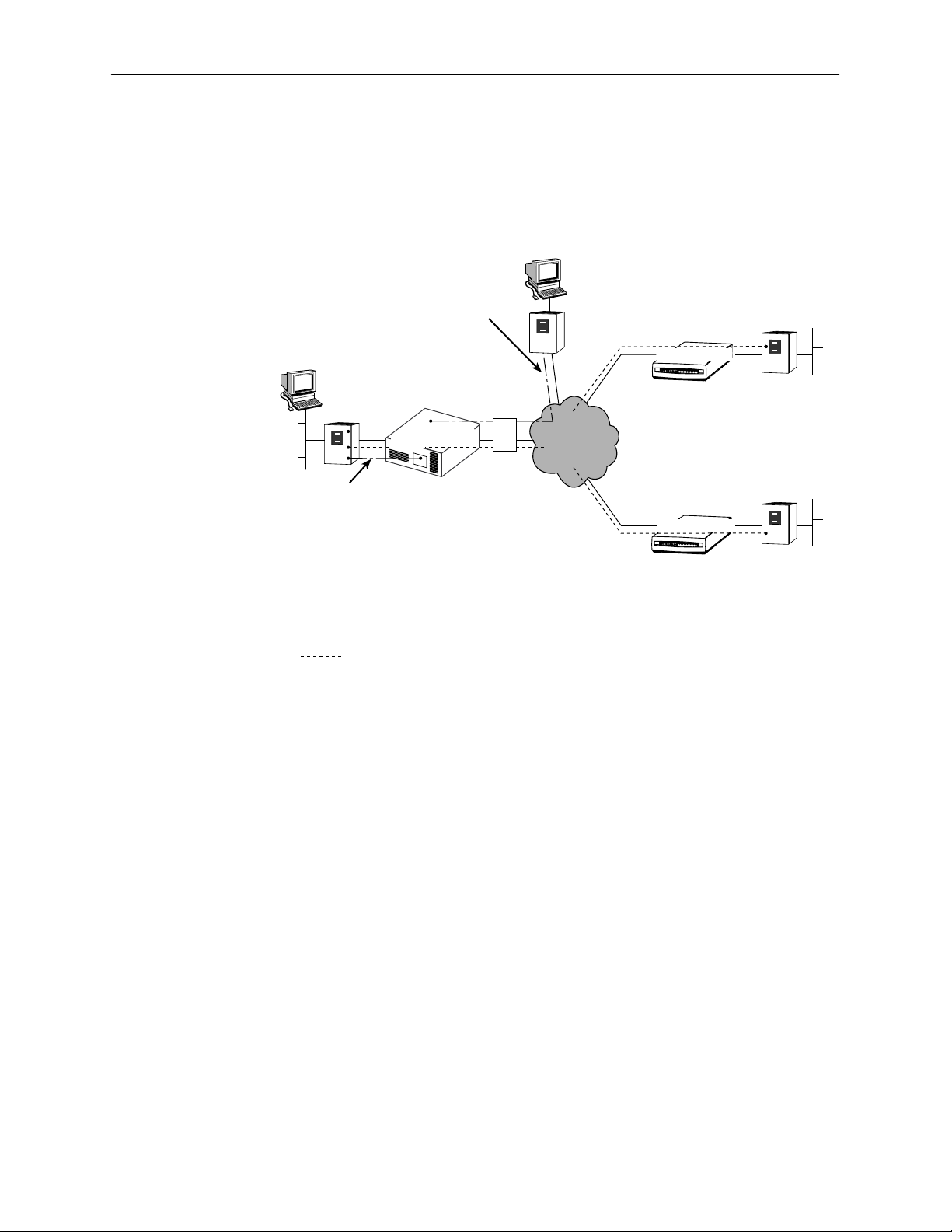
The following illustration shows a network that includes FrameSaver units at the
central site and remote sites. User data PVCs provide LAN-to-LAN connectivity
between the central site and the remote sites.
Corporate
Headquarters
Frame
Relay
Router
For Local
Management
DLCI/EDLCIs:
100/0 User Data for Branch Office A
200/0 User Data for Branch Office B
100/2 Management Data for Branch Office A
200/2 Management Data for Branch Office B
For NOC
Management
Port
NET
FrameSaver
TM
SLV
Central Site
FrameSaver
Unit
Network
Operations
Inverse
Multiplexer
or NTU
Center
Frame
Network
NMS
Frame
Relay
Router
100
Relay
200
Branch Office A
Remote Site
FrameSaver
Unit
NET Port
DLCI/EDLCIs:
100/0 User Data
100/2 Management Data
Remote Site
FrameSaver
Unit
NET Port
DLCI/EDLCIs:
200/0 User Data
200/2 Management Data
Frame
Relay
Router
Frame
Relay
Router
Branch Office B
Multiplexed PVC
Dedicated Management PVC (Non-multiplexed)
00-16787
The central site FrameSaver unit ordinarily is configured for management from a
Network Management System (NMS), through either the attached router, as
shown in the above figure, or through the Network Operations Center (NOC)
router (for management by the Network Service Provider). Multiple management
PVCs then connect the central site unit to the remote site units using Paradyne’s
proprietary PVC multiplexing method (embedded DLCIs).
1-2
June 2000
9820-A2-GB20-20
Page 17

About FrameSaver SLV In-Line Monitors
FrameSaver SLV In-Line Monitor Features
The FrameSaver SLV in-line monitor provides the following features:
H Intelligent Service Level Verification. Provides accurate throughput,
latency, and availability measurements to determine network performance
and whether service level agreements (SLAs) are being met, along with SLA
reporting. SLA parameter thresholds can be configured to provide proactive
notification of a developing network problem.
H Security. Provides multiple levels of security to prevent unauthorized access
to the unit.
H TruePutt Technology. Using Frame Delivery Ratios (FDR) and Data
Delivery Ratios (DDR), throughput (within and above CIR, as well as between
CIR and EIR, and above EIR) can be measured precisely, eliminating
inaccuracies due to averaging. These ratios are available through OpenLane
SLV reports.
H Frame Relay Aware Management. Supports diagnostic and network
management features over the frame relay network using the Annex-A,
Annex-D, and Standard UNI (User Network Interface) LMI management
protocol. The unit’s frame relay capability also supports:
— Inband management channels over the frame relay network using
dedicated PVCs.
— Unique nondisruptive diagnostics.
— CIR monitoring on a PVC basis.
— Multiple PVCs on an interface.
— Multiplexing management PVCs with user data PVCs.
— Multiplexing multiple PVCs going to the same location onto a single
network PVC.
H Auto-Configuration. Provides the following automatic configuration features:
— Frame Relay Discovery – For automatic discovery of network DLCIs and
configuration of a user data port DLCI, the PVC connection, and a
management PVC, which is multiplexed with user data DLCIs.
— LMI Protocol Discovery – For automatic configuration of the protocol
being used by the network.
— DLCI Deletion – For automatic removal of configuration of unused DLCIs
from the unit’s configuration and statistical databases.
— CIR Determination – For automatic recalculation of the committed rate
measurement interval (Tc) and excess burst size (Be) when a DLCI’s CIR
changes.
Excess burst size (Be) and committed burst size (Bc) are recalculated
when Committed Burst Size Bc (Bits) is set to CIR. The committed rate
measurement interval (Tc) is recalculated when Committed Burst Size Bc
(Bits) is set to Other.
9820-A2-GB20-20
June 2000
1-3
Page 18

About FrameSaver SLV In-Line Monitors
H RMON-Based User History Statistics Gathering. Provides everything
needed to monitor network service levels, plus throughput with accurate data
delivery, network latency, and LMI and PVC availability.
In addition, port bursting statistics are kept for all frame relay links. These
statistics are available real-time via the Enterprise MIB and historically as an
RMON2 User History object. In future releases of the OpenLane SLM
system, this will enable even more accurate calculations of utilization.
H Network User History Synchronization. Allows correlation of RMON2 User
History statistics among all SLV devices in a network for more accurate
OpenLane SLV reports. Using a central clock, called the network reference
time, all SLV device user history statistics are synchronized across the
network, further enhancing the accuracy of OpenLane SLV reports.
H Extensive Testing Capability. Provides a variety of tests to identify
and diagnose device, network, and other problems. These tests can be
commanded from the unit’s menu-driven user interface or the OpenLane
system (using its easy-to-use Diagnostic Troubleshooting feature).
H Dedicated Troubleshooting PVC. Provides a troubleshooting management
link that helps service providers isolate problems within their network. This
feature can be configured from the menu-driven user interface.
H Maximum Number of PVCs and Management PVCs Supported.
Feature
Through
Connections
(PVCs)
Dedicated
Management
PVCs
FrameSaver
SLV 9820
16 120 250 512
2 2 2 2
FrameSaver
SLV 9820-2M
FrameSaver
SLV 9820-8M
FrameSaver
SLV 9820-45M
H Router-Independence. Unique diagnostics, performance monitoring,
PVC-based in-band network management, and SNMP connectivity is not
dependent upon external routers, cables, or LAN adapters.
H Inverse ARP and Standard RIP Support. Provides Inverse ARP (Address
Resolution Protocol) support so the frame relay router at one end of a
management PVC can acquire the IP address of a FrameSaver unit at the
other end of the PVC. Standard RIP (Routing Information Protocol) allows the
router to automatically learn the routes to all FrameSaver units connected to
that FrameSaver unit.
H LMI Packet Capture. Provides a way to upload data that has been captured
in a trace file so the data can be uploaded and transferred to a Network
Associates Sniffer for analysis, or viewed via the menu-driven user interface.
The 12 most recent LMI messages can be displayed from the menu-driven
user interface.
1-4
June 2000
9820-A2-GB20-20
Page 19

About FrameSaver SLV In-Line Monitors
H ATM VPI/VCI and DLCI Correlation. For networks with both ATM and frame
relay-access endpoints, allows the FrameSaver unit to report the originating
Virtual Path or Channel Identifier (VPI/VCI) in the far-end ATM-access
endpoint where the local DLCI is mapped so they can be correlated for
OpenLane SLV reports.
H Back-to-Back Operation. Allows two FrameSaver devices to be connected
via a leased-line network or simulation so a point-to-point configuration can
be implemented.
H Configuration Upload/Download and Software Download Capability.
Provides quick transfer of configuration options to and from nodes and
software downloads while the unit is running using the standard File Transfer
Protocol (FTP). Two software images can be stored.
H Dual Flash Memory. Allows software upgrades while the unit is up and
running. Two software loads can be stored and implemented at the user’s
discretion.
H OpenLane Service Level Management Solution. Provides an
advanced, standards-based performance monitoring and management
application.
Being standards-based, the OpenLane SLM system can also be used with
other management applications like HP OpenView or IBM’s NetV iew.
OpenLane includes HP OpenView adapters for integrating OpenLane
features with the OpenView Web interface.
Being Web-based, the OpenLane system provides Web access to the data
contained in the database to provide anytime, anywhere access to this
information via a Web browser.
Some of the OpenLane SLM system’s features include:
— Real-time performance graphs provide exact performance measurement
details (not averages, which can skew performance results) of service
level agreement (SLA) parameters.
— Historical SLV graphs provide service level management historical
reports so frame relay SLAs can be verified.
— Diagnostic troubleshooting provides an easy-to-use tool for performing
tests, which include end-to-end, PVC loopback, connectivity, and physical
interface tests.
— Basic configuration allows you to configure FrameSaver devices, and set
RMON alarms and thresholds. Network DLCI Circuit IDs can also be
assigned.
— Automatic SLV device and PVC discovery allows all SLV devices with
their SLV Delivery Ratio configuration option enabled to be discovered
automatically, along with their PVCs.
— A FrameSaver unit can be reset from the OpenLane system.
— Firmware downloading provides an easy-to-use tool for downloading to
an entire network or a portion of the network.
— On-demand polling of FrameSaver devices, and SNMP polling and
reporting are available.
9820-A2-GB20-20
June 2000
1-5
Page 20

About FrameSaver SLV In-Line Monitors
H NetScout Manager Plus and NetScout Probe Support. Provides complete
LAN and WAN traffic analysis and monitoring functions for FrameSaver SLV
devices. The following features are supported using this application:
— Thresholds for RMON 1 (Remote Monitoring, Version 1) alarms and
events can be configured.
— (Models 9820 and 9820-2M.) Performance monitoring can be performed
using collected RMON 2 (Version 2) data. NetScout Manager Plus’s
Protocol Directory and Distribution functionality allows FrameSaver SLV
9820 and 9820-2M units to measure up to eleven network-layer protocols
and report the amount of traffic generated by each. Its IP Top Talkers and
Listeners reporting identifies the devices using network bandwidth for
traffic and protocol analysis, identifying the network’s top six users. In
addition, it collects performance statistics from FrameSaver devices. Up
to 900 samples can be stored in 15-minute buckets, with 96 buckets in a
24-hour period, for up to five days worth of data.
— Optional standalone NetScout Probes can be used with FrameSaver
devices at sites where full 7-layer monitoring, an unlimited number of
protocols, and advanced frame capture and decode capabilities are
desired.
OSI Layers Monitored
Using:
FrameSaver SL V 1–3 1–3 1–2 1–2
Netscout Probe 3–7 3–7 3–7 3–7
9820 9820-2M 9820-8M 9820-45M
H Hardware Bypass Feature. In the event of catastrophic system failure or
power loss, data traffic is routed through hardware directly between the
network port and the user data port.
1-6
June 2000
9820-A2-GB20-20
Page 21

User Interface and Basic Operation
This chapter tells you how to access, use, and navigate the menu-driven user
interface. It includes the following:
H
Logging On
H
Main Menu
H
Screen Work Areas
H
Navigating the Screens
2
—
Keyboard Keys
—
Function Keys
—
Selecting from a Menu
—
Switching Between Screen Areas
—
Selecting a Field
—
Entering Information
What appears on the screens depends on:
H Current configuration – How your network is currently configured.
H Security access level – The security level set by the system administrator
for each user.
H Data selection criteria – What you entered in previous screens.
9820-A2-GB20-20
June 2000
2-1
Page 22

User Interface and Basic Operation
Logging On
Start a session using one of the following methods:
H Telnet session via:
— An in-band management channel through the frame relay network.
— A local in-band management channel configured on the DTE port
between the FrameSaver unit and the router.
H Dial-in connection using the internal modem (Model 9820-45M).
H Direct terminal connection over the COM port (Terminal port on the
Model 9820-45M).
When logging on, the User Interface Idle screen appears.
H If no security was set up or security was disabled, the Main Menu screen
Main Menu
(see
H If security was set up and is enabled, you are prompted for a login. Enter
your login ID and password.
on page 2-4) appears. You can begin your session.
When the user interface has been idle, a session is automatically ended and the
screen goes blank when the unit times out. Press Enter to reactivate the
interface.
" Procedure
To log in when security is being enforced:
1. Type your assigned Login ID and press Enter.
2. Type your Password and press Enter.
— Valid characters – All printable ASCII characters
— Number of characters – Up to 10 characters can be entered in the
Login ID and Password fields
— Case-sensitive – Yes
An asterisk (*) appears in the password field for each character entered.
2-2
June 2000
9820-A2-GB20-20
Page 23

User Interface and Basic Operation
If your login was . . . Then the . . .
V alid Main Menu appears. Begin your session.
Invalid Message, Invalid Password, appears on line 24, and
the Login screen is redisplayed.
After three unsuccessful attempts:
– A Telnet session is closed.
– The User Interface Idle screen appears for a directly
connected terminal.
– An external modem is disconnected.
– An SNMP trap is generated.
Access is denied.
See your system administrator to verify your login (Login
ID/Password combination).
If two sessions are already active, wait and try again.
H If attempting to access the unit through Telnet, the local Telnet client process
returns a Connection refused: message.
H If attempting to access the unit over the COM (or Terminal) port or Modem
port, not via Telnet, the User Interface Already In Use screen is redisplayed.
The type of connection (Telnet connection, direct COM (or Terminal) port
connection, or direct Modem port connection) for each current user is
identified, along with the user’s login ID.
" Procedure
To end the session:
1. Press Ctrl-a to switch to the function keys area of the screen.
2. Type e (E
— For a COM (Terminal) port-connected terminal, the session is ended.
— For a modem port-connected terminal, the session is ended and the
— For a Telnet connection, the session is closed and, if no other Telnet or
If ending a session from the Configuration branch, see
Options
xit) and press Enter.
modem is disconnected.
FTP session is occurring over the connection, the modem is
disconnected.
Saving Configuration
in Chapter 3,
Configuration Procedures
.
9820-A2-GB20-20
June 2000
2-3
Page 24
User Interface and Basic Operation
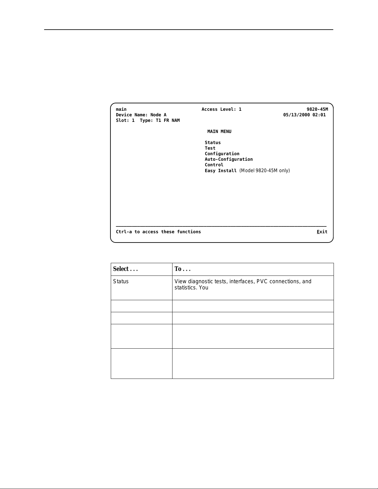
Main Menu
Entry to all of the FrameSaver unit’s tasks begins at the Main Menu, which has
five menus or branches. The Access Level at the top of the screen only appears
when security has been set up.
main Access Level: 1 9820-45M
Device Name: Node A 05/13/2000 02:01
Slot: 1 Type: T1 FR NAM
MAIN MENU
Status
Test
Configuration
Auto-Configuration
Control
Easy Install
(Model 9820-45M only)
–––––––––––––––––––––––––––––––––––––––––––––––––––––––––––––––––––––––––––––––
Ctrl-a to access these functions E
xit
Select . . . To . . .
Status View diagnostic tests, interfaces, PVC connections, and
statistics. You can also display LEDs and FrameSaver unit
identity information.
Test Select and cancel test for the FrameSaver unit’s interfaces.
Configuration Display and edit the configuration options.
Auto-Configuration Configure basic access unit setup automatically based upon a
selected application. You can automatically populate network
and data port DLCI configuration options with numeric settings.
Control Control the asynchronous user interface for call directories,
device naming, login administration, and selecting software
releases. You can also initiate a power-on reset of the
FrameSaver unit.
See Appendix A,
Menu Hierarchy
, for a pictorial view of the menu hierarchy,
which represents the organization of the FrameSaver unit’s menus and screens.
2-4
June 2000
9820-A2-GB20-20
Page 25
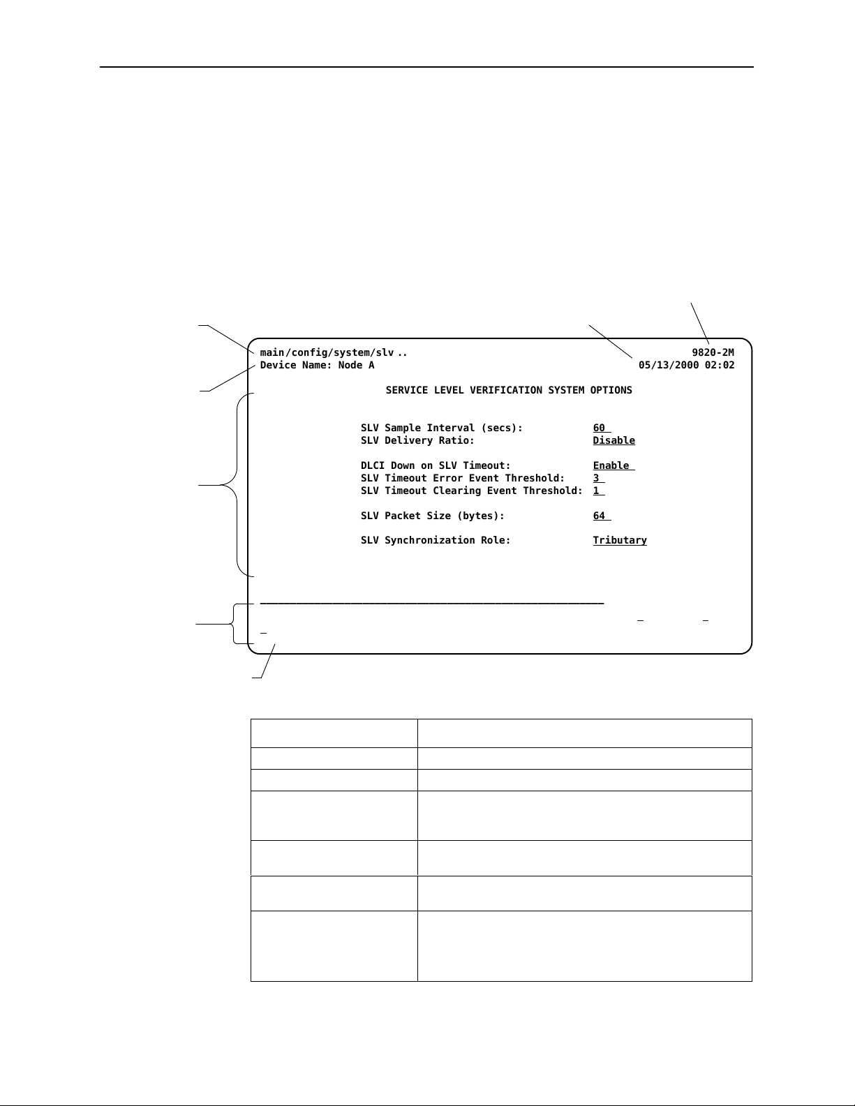
Screen Work Areas
There are two user work areas:
H Screen area – Where you input information into fields.
H Function keys area – Where you perform specific screen functions.
Below is a sample configuration screen showing a 2 Mbps unit.
Menu Path
main/config/system/slv 9820-2M. .
Device Name: Node A 05/13/2000 02:02
User Interface and Basic Operation
Model Number
Date and Time
Device
Name
Screen
Area
Function
Keys Area
Message Area
SERVICE LEVEL VERIFICATION SYSTEM OPTIONS
SLV Sample Interval (secs): 60
SLV Delivery Ratio: Disable
DLCI Down on SLV Timeout: Enable
SLV Timeout Error Event Threshold: 3
SLV Timeout Clearing Event Threshold: 1
SLV Packet Size (bytes): 64
SLV Synchronization Role: Tributary
–––––––––––––––––––––––––––––––––––––––––––––––––––––––––––––––––––––––––––––––
Ctrl-a to access these functions, ESC for previous menu M
S
ave
ainMenu Exit
Screen Format Description
Menu Path Menu selections made to reach the current screen.
Device Name Customer-assigned identification of the FrameSaver unit.
9820 FrameSaver unit’s model number: the 128 kbps 9820,
2 Mbps 9820-2M, 8 Mbps 9820-8M, or 45 Mbps
9820-45M.
Screen Area Selection, display, and input fields for monitoring and
maintaining the FrameSaver unit.
Function Keys Area Specific functions that can be performed by pressing a
specified key, then pressing Enter.
Message Area System-related information and valid settings for input
fields in the lower left corner.
System and Test Status messages in the lower right
corner.
9820-A2-GB20-20
June 2000
2-5
Page 26

User Interface and Basic Operation
Navigating the Screens
You can navigate the screens by:
H Using keyboard keys.
H Switching between the two screen work areas using function keys.
Keyboard Keys
Use the following keyboard keys to navigate within the screen area:
Press . . . To . . .
Ctrl-a Move cursor between the screen area and the
Esc Return to the previous screen.
screen function keys area.
Right Arrow (on same screen row), or
Tab (on any screen row)
Left Arrow (on same screen row), or
Ctrl-k
Backspace Move cursor one position to the left or to the
Spacebar Select the next valid value for the field.
Delete (Del) Delete character that the cursor is on.
Up Arrow or Ctrl-u Move cursor up one field within a column on the
Down Arrow or Ctrl-d Move cursor down one field within a column on
Right Arrow or Ctrl-f Move cursor one character to the right if in edit
Left Arrow or Ctrl-b Move cursor one character to the left if in edit
Ctrl-l Redraw the screen display, clearing information
Enter (Return) Accept entry or, when pressed before entering
Move cursor to the next field.
Move cursor to the previous field.
last character of the previous field.
same screen.
the same screen.
mode.
mode.
typed in but not yet entered.
data or after entering invalid data, display valid
options on the last row of the screen.
2-6
June 2000
9820-A2-GB20-20
Page 27

Function Keys
User Interface and Basic Operation
All function keys (located in the lower part of the screen) operate the same way
throughout the screens. They are not case-sensitive, so upper- or lowercase
letters can be used interchangeably.
These keys use the following conventions:
For the screen
Select . . .
M or m MainMenu Return to the Main Menu screen.
E or e Exit Terminate the asynchronous terminal session.
N or n New Enter new data.
O or o Modify Modify existing data.
L or l Delete Delete data.
S or s Save Save information.
function . . .
And press Enter to . . .
R or r Refresh Update screen with current information.
C or c ClrStats Clear network performance statistics and refresh the
screen.
V ariations include:
H ClrSLV&DLCIStats for clearing SLV and DLCI
statistics.
H ClrLinkStats for clearing frame relay link statistics.
U or u PgUp Display the previous page.
D or d PgDn Display the next page.
9820-A2-GB20-20
June 2000
2-7
Page 28

User Interface and Basic Operation
Selecting from a Menu
Procedure
"
To select from a menu:
1. Tab or press the down arrow key to position the cursor on a menu selection,
or press the up arrow key to move the cursor to the bottom of the menu list.
Each menu selection is highlighted as you press the key to move the cursor
from position to position.
2. Press Enter. The selected menu or screen appears.
" Procedure
To return to a previous screen, press the Escape (Esc) key until you reach the
desired screen.
Switching Between Screen Areas
Use Ctrl-a to switch between screen areas.
" Procedure
To switch to the function keys area:
1. Press Ctrl-a to switch from the screen area to the function keys area.
2. Select either the function’s designated (underlined) character or
Tab to the desired function key.
3. Press Enter. The function is performed.
To return to the screen area, press Ctrl-a again.
2-8
June 2000
9820-A2-GB20-20
Page 29

Selecting a Field
Entering Information
User Interface and Basic Operation
Once you reach the desired menu or screen, select a field to view or change, or
issue a command.
Press the Tab or right arrow key to move the cursor from one field to another. The
current setting or value appears to the right of the field.
You can enter information in one of three ways. Select the field, then:
H Manually type in (enter) the field value or command.
Example:
Entering bjk as a user’s Login ID on the Administer Logins screen (from the
Control menu/branch).
H Type in (enter) the first letter(s) of a field value or command, using the unit’s
character-matching feature.
Example:
When configuring a port’s physical characteristics with the Port (DTE)
Initiated Loopbacks configuration option/field selected (possible settings
include Disable, Local, DTPLB, DCLB, and Both), entering d or D displays
the first value starting with d – Disable. In this example, entering dt or DT
would display DTPLB as the selection.
H Switch to the function keys area and select or enter a designated
function key.
Example:
To save a configuration option change, select Save. S or s is the designated
function key.
If a field is blank and the Message area displays valid selections, press the
spacebar; the first valid setting for the field appears. Continue pressing the
spacebar to scroll through other possible settings.
9820-A2-GB20-20
June 2000
2-9
Page 30

User Interface and Basic Operation
This page intentionally left blank.
2-10
June 2000
9820-A2-GB20-20
Page 31

Configuration Procedures
This chapter includes the following:
Basic Configuration
H
—
Configuration Option Areas
—
Accessing and Displaying Configuration Options
—
Changing Configuration Options
—
Saving Configuration Options
—
Minimal Configuration Before Deploying Remote Units
3
9820-A2-GB20-20
June 2000
3-1
Page 32

Configuration Procedures
Basic Configuration
Configuration option settings determine how the FrameSaver unit operates. Use
the FrameSaver unit’s Configuration Edit/Display menu to display or change
configuration option settings.
The Configuration Edit/Display menu of a FrameSaver SLV 9820-2M is shown
below.
Configuration Menu
main/config 9820-2M
Device Name: Node A 5/13/2000 23:32
CONFIGURATION EDIT/DISPLAY
System
Network
Data Ports
PVC Connections
Management and Communication
––––––––––––––––––––––––––––––––––––––––––––––––––––––––––––––––––––––––––––––––
Ctrl-a to access these functions, ESC for previous menu M
S
ave
ainMenu Exit
Changing an Auto-Configuration setting can also change the FrameSaver unit’s
configuration. See
Setting Up Auto-Configuration
for additional information.
3-2
June 2000
9820-A2-GB20-20
Page 33

Configuration Option Areas
The FrameSaver unit arrives with configured factory default settings, which are
located in the Factory Default Configuration option area. You can find the default
settings for configuration options in the:
H
FrameSaver SLV, Models 9820, 9820-2M, 9820-8M, and 9820-45M, Quick
Reference
H
Configuration Option Tables
If the factory default settings do not support your network’s configuration, you can
customize the configuration options to better suit your application.
Four configuration option storage areas are available.
Configuration Procedures
Configuration Option Area
Current Configuration The currently active set of configuration options.
Customer Configuration 1 An alternate set of configuration options that the
Customer Configuration 2 Another alternate set of configuration options that the
Default Factory Configuration A read-only configuration area containing the factory
Description
customer can set up and store for future use.
customer can set up and store for future use.
default set of configuration options.
You can load and edit default factory configuration
settings, but you can only save those changes to the
Current, Customer 1, or Customer 2 configuration
option areas.
The Current, Customer 1, and Customer 2 configuration
option areas are identical to the Default Factory
Configuration until modified by the customer.
9820-A2-GB20-20
June 2000
3-3
Page 34

Configuration Procedures
Accessing and Displaying Configuration Options
To access and display configuration options, load (copy) the applicable
configuration option set into the edit area.
" Procedure
To load a set of configuration options for editing:
1. From the Main Menu, press the down arrow key so the cursor is on
Configuration.
2. Press Enter to display the Configuration menu. The Load Configuration
From: menu appears.
NOTE:
Loading a configuration with many DLCIs from a unit’s Customer
Configuration 1 or 2 option area may take time. Allow a minute or more
for the file to be loaded.
3. Select the configuration option area from which you want to load
configuration options and press Enter (Current Configuration, Customer
Configuration 1, Customer Configuration 2, or Default Factory Configuration).
The selected set of configuration options is loaded into the configuration edit
area and the Configuration Edit/Display menu appears.
This sequence of steps would be shown as the menu selection sequence:
Main Menu→Configuration
3-4
June 2000
9820-A2-GB20-20
Page 35

Changing Configuration Options
Procedure
"
To change configuration option settings:
1. From the Configuration Edit/Display menu, select a set of configuration
options and press Enter.
For example:
Configuration→PVC Connections
2. Select the configuration options that are applicable to your network, and
make appropriate changes to the setting(s). See Chapter 2,
and Basic Operation
When creating new PVC connections or management PVCs, some
configuration options will be blank. For a valid setting to appear, Tab to the
configuration option and press the spacebar.
3. Repeat Steps 1 and 2 until all changes are complete.
NOTE:
— Only Security Access Level 1 users can change configuration options.
Configuration Procedures
User Interface
, for additional information.
— Security Access Level 2 users can only view configuration options and
run tests.
— Security Access Level 3 users can only view configuration options; they
cannot change configuration options or run tests.
9820-A2-GB20-20
June 2000
3-5
Page 36

Configuration Procedures
Saving Configuration Options
When changes to the configuration options are complete, use the Save function
key to save your changes to either the Current, Customer 1, or Customer 2
configuration areas.
NOTE:
When changing settings, you must Save for changes to take effect.
" Procedure
To save the configuration option changes:
1. Press Ctrl-a to switch to the function key area at the bottom of the screen.
2. Type s or S to select the S
The Save Configuration To: screen appears.
ave function and press Enter.
NOTE:
If you try to exit the Configuration menu without saving changes, a Save
Configuration screen appears requiring a Yes or No response.
— If you select No, the Main Menu screen reappears and the changes
are not saved.
— If you select Y
3. Select the configuration option area to which you want to save your changes
(usually the Current Configuration) and press Enter.
When Save is complete, Command Complete appears in the message area
at the bottom of the screen.
es, the Save Configuration To: screen appears.
NOTE:
There are other methods of changing configurations, like SNMP and
Auto-Configuration. Since multiple sessions can be active at the same
time, the last change made overwrites any previous or current changes
being made. For instance:
— Saving your configuration changes would cause configuration
changes made via another method to be lost.
— If you are making changes and someone else makes changes and
saves them, your changes would be lost.
Minimal Configuration Before Deploying Remote Units
At a minimum, the following configuration options must be set before deploying a
a FrameSaver unit to a remote site:
H Node IP Address
H Node Subnet Mask
3-6
June 2000
9820-A2-GB20-20
Page 37

Configuration Options
This chapter includes the following:
Configuring Using the Easy Install Screen (Model 9820-45M)
H
H
Entering System Information and Setting the System Clock
H
Setting Up for Trap Dial-Out (Models 9820, 9820-2M, 9820-8M)
—
Setting Up an External Modem for Trap Dial-Out
—
Setting Up Call Directories for Trap Dial-Out
4
H
Setting Up Auto-Configuration
—
Selecting a Frame Relay Discovery Mode
—
Automatically Removing a Circuit
H
Setting Up Management
—
Setting Up Local Management at the Central Site
—
Setting Up So the Router Can Receive RIP
—
Setting Up Service Provider Connectivity at the Central Site
H
Setting Up Back-to-Back Operation
—
Changing Operating Mode
H
Configuration Option Tables
H
Configuring the Overall System
—
Configuring Frame Relay and LMI for the System
—
Configuring Service Level Verification Options
—
Configuring General System Options
H
Configuring the Physical Interfaces
9820-A2-GB20-20
—
Configuring the Network Data Port
—
Configuring the User Data Port
June 2000
4-1
Page 38

Configuration Options
H
Configuring Frame Relay for an Interface
H
Manually Configuring DLCI Records
H
Configuring PVC Connections
H
Setting Up Management and Communication Options
—
Configuring Node IP Information
—
Configuring Management PVCs
—
Configuring General SNMP Management
—
Configuring Telnet and/or FTP Session Support
—
Configuring SNMP NMS Security
—
Configuring SNMP Traps and Trap Dial-Out
—
Configuring the Ethernet Port (Model 9820-45M)
—
Configuring the Communication Port
—
Configuring the COM Port to Support an External Modem
(Models 9820, 9820-2M, 9820-8M)
—
Configuring the Modem Port (Model 9820-45M)
4-2
June 2000
9820-A2-GB20-20
Page 39

Configuring Using the Easy Install Screen (Model 9820-45M)
The Easy Install screen provides direct access to the configuration options
required to establish communication and prepare for Auto-Configuration.
Main Menu→Easy Install
Table 4-1. Easy Install Configuration Options (1 of 2)
Node IP Address
Possible Settings: 001.000.000.000 – 223.255.255.255, Clear
Default Setting: Clear (000.000.000.000)
Specifies the IP address needed to access the node. Since an IP address is not bound
to a particular port, it can be used for remote access via a management PVC.
This address may be shared only among management PVCs.
001.000.000.000 – 223.255.255.255 – Shows the IP address for the node, which can be
viewed or edited.
Clear – Fills the node IP address with zeros.
Configuration Options
Node Subnet Mask
Possible Settings: 000.000.000.000 – 255.255.255.255, Clear
Default Setting: 000.000.000.000
Specifies the subnet mask needed to access the node. Since the subnet mask is not
bound to a particular port, it can be used for remote access via a management PVC.
000.000.000.000 – 255.255.255.255 – Shows the subnet mask for the node, which can
be viewed or edited.
Clear – Fills the node subnet mask with zeros. When the node’s subnet mask is
all zeros, the IP protocol creates a default subnet mask based upon the class of the
IP address: Class A: 255.000.000.000, Class B: 255.255.000.000, or Class C:
255.255.255.000.
TS Access (Type)
Possible Settings: None, DLCI
Default Setting: None
Specifies whether a DLCI is defined for troubleshooting by the service provider.
None – A troubleshooting DLCI is not defined.
DLCI – A troubleshooting DLCI is defined. Its value must be entered in the next field.
TS Access (DLCI)
Possible Settings: 16–1007
Default Setting: blank
Specifies the DLCI on the network interface to be used for troubleshooting by the
service provider.
16 – 1007 – Specifies the DLCI.
Create a Dedicated Network Management Link
9820-A2-GB20-20
With the cursor on the Create a Dedicated Network Management Link field, press Enter.
When prompted, enter a DLCI for the link from 16 to 1007. The management link DLCI
is added or modified.
June 2000
4-3
Page 40

Configuration Options
Table 4-1. Easy Install Configuration Options (2 of 2)
Ethernet Port Options Screen
With the cursor on the Ethernet Port Options Screen field, press Enter. The Ethernet
Port Options screen appears. See
After configuring the Ethernet port configuration options, save your changes. Then
press ESC to return to the Easy Install screen.
Entering System Information and Setting the System Clock
Select System Information to set up or display the general SNMP name for the
unit, its location, and a contact for the unit, as well as to set the system clock.
Main Menu→Control→System Information
The following information is available for viewing. Save any entries or changes.
Configuring the Ethernet Port
on page 4-50.
If the selection is . . .
Device Name Unique name for device identification of up to 20 characters.
System Name SNMP system name; can be up to 255 characters.
System Location System’s physical location; can be up to 255 characters.
System Contact Name and how to contact the system person; can be up to
Date Current date in the month/day/year format (mm/dd/yyyy).
Time
Enter the . . .
255 characters.
Current time in the hours:minutes format (hh:mm:ss).
NOTE:
To clear existing information, place the cursor in the Clear field (Tab to the
Clear field) and press Enter.
See Chapter 5,
Security and Logins
, to set up and administer logins.
4-4
June 2000
9820-A2-GB20-20
Page 41

Setting Up for Trap Dial-Out (Models 9820, 9820-2M, 9820-8M)
An external modem can be attached to the COM port for dialing out when an
SNMP trap is generated.
To set up an external modem, you need to:
1. Set up SNMP trap managers.
2. Set up an external modem.
3. Set up Modem Directory phone numbers.
4. Configure trap dial-out.
Configuration Options
Configuring SNMP NMS Security
See
Setting Up Call Directories for Trap Dial-Out
See
See
Configuring SNMP Traps and Trap Dial-Out
Setting Up an External Modem for Trap Dial-Out
(Models 9820, 9820-2M, 9820-8M.) When trap dial-out is desired, the PC or
asynchronous terminal must be disconnected from the unit’s COM port when
setup is complete, and an external modem connected instead. See
the COM Port to Support an External Modem
Setting Up Call Directories for Trap Dial-Out
(Models 9820, 9820-2M, 9820-8M.) To set up call directories:
" Procedure
1. Set up directory phone numbers.
Main Menu→Control→Modem Call Directories
2. Select Directory Number A (for Alarm).
3. Enter the phone number(s).
Valid characters include . . .
to set up SNMP trap managers.
when trap dial-out is desired.
for trap and alarm information.
Configuring
for additional information.
For . . .
9820-A2-GB20-20
ASCII text Entering the phone number.
Space,
underscore ( _ ), and
dash (–)
Comma (,) Readability character for a 2-second pause.
B Blind dialing.
P Pulse dialing, unless B is specified.
T Tone dialing, unless B is specified.
W Wait for dial tone.
4. Save the phone number(s).
June 2000
Readability characters.
4-5
Page 42

Configuration Options
Setting Up Auto-Configuration
The auto-configuration feature allows you to select a method of automatic
configuration and connection of DLCIs within the FrameSaver unit, as well as to
automatically remove DLCIs and connections that are no longer supported by the
network service provider. Auto-configuration also maintains associated DLCI
option settings when Standard LMI is used on the network data port.
Main Menu→Auto-Configuration
Auto-Configuration Screen Example
main/auto-configuration 9820–2M
Device Name: Node A 5/13/2000 23:32
Frame Relay Discovery Mode: 1MPort
Automatic Circuit Removal: Enable
AUTO-CONFIGURATION
––––––––––––––––––––––––––––––––––––––––––––––––––––––––––––––––––––––––––––––––
Ctrl-a to access these functions, ESC for previous menu M
S
ave
ainMenu Exit
4-6
June 2000
9820-A2-GB20-20
Page 43

Selecting a Frame Relay Discovery Mode
When a Frame Relay Discovery Mode is active, the FrameSaver unit “discovers”
network DLCIs from the network LMI status response message. It configures a
network DLCI, a user data port DLCI, and automatically connects them to create
a PVC.
Main Menu→Auto-Configuration→Frame Relay Discovery Mode
Automatically configured network DLCIs are multiplexed, and each automatically
configured port DLCI carries the same DLCI Number as its corresponding
network DLCI. These are the same DLCI numbers that would have been
available had the FrameSaver unit not been inserted in the link, between your
equipment and the network.
NOTE:
A local Management PVC (e.g., the PVC between the router and the
FrameSaver unit’s user data port) must be configured manually; it cannot
be configured automatically (see
Central Site
).
Configuration Options
Setting Up Local Management at the
The following will occur when a Frame Relay Discovery Mode is selected:
Discovery Mode Configuration Description
1MPort
(default)
1Port H Auto-configuration is enabled on Port-1.
NetOnly H Auto-configuration of a network DLCI only; no Port-1 or
Disable H No frame relay discovery or automatic configuration
H Auto-configuration is enabled on Port-1.
H A management DLCI is configured.
H A multiplexed network DLCI containing two embedded
DLCIs (EDLCIs) is configured for Port-1 user data and
management data.
H A PVC connection is configured between the network
and port DLCIs.
H No management DLCI is configured.
H A multiplexed network DLCI is configured for Port-1
user data.
H A PVC connection is configured between the network
and port DLCIs.
PVC connections are configured.
H No Port-1, PVC connection, or management DLCI is
configured.
takes place.
The FrameSaver unit will be configured manually .
9820-A2-GB20-20
June 2000
4-7
Page 44

Configuration Options
NOTE:
If 1MPort (the default) is not the setting required for your application, change
the Frame Relay Discovery Mode before connecting the network cable or
editing discovered option settings. Otherwise, the FrameSaver unit will start
“discovering” DLCIs as soon as it powers up.
To recover from this problem, edit a selected “discovered” DLCI or PVC
connection manually if any DLCIs or PVC Connections have been configured
manually. If only a local management PVC between the router and the
FrameSaver unit has been configured, select the desired Frame Relay
Discovery Mode and S
The default discovery mode is 1MPort (management DLCIs multiplexed with data
DLCIs on Port-1, which creates two embedded DLCIs [EDLCIs] – one EDLCI for
Port-1 user data, and another EDLCI for management data); that is, for each
DLCI discovered on the network, a multiplexed network DLCI and a standard
data port DLCI will be configured and connected, and a Management PVC will be
embedded in the network DLCI. When LMI is active on the network interface and
PVC status information (with provisioned DLCI numbers) is next received from
the network, the unit automatically saves the settings to the Current Configuration
area.
ave the change.
Configuration options set by the selected discovery mode can be manually
modified, refined, or deleted at any time using the Configuration menus.
No previously discovered and configured DLCIs or cross-connections will be
removed unless authorized or Automatic Circuit Removal is enabled (see
Automatically Removing a Circuit
according to the current Frame Relay Discovery Mode setting. Selecting or
changing the setting will not affect IP Addresses or Subnet Masks.
). Additional discovered DLCIs will be configured
NOTE:
When auto-configuration creates a multiplexed DLCI, but a standard DLCI is
needed, change the DLCI to standard from the network DLCI Records
screen:
Configuration→Network→DLCI Records
4-8
June 2000
9820-A2-GB20-20
Page 45

Configuration Options
When a Frame Relay Discovery Mode is changed and saved, the Saving will
cause Auto-Configuration to update and Restart. Are you
sure? prompt appears. N
o is the default for this prompt.
H If Y
H If N
es (y) is entered, the Delete All DLCIs and PVC Connections?
prompt appears. N
es is entered, all multiplexed DLCIs and PVC Connections are
— If Y
deleted, except for Management PVCs with the user data port as the
primary destination and the Management PVC that is designated as
TS Management Link.
— If N
no Auto-Configuration updates are performed and updates due to LMI
response messages are performed according to the previously saved setting.
o is entered, previously discovered and auto-configured option
settings will not be removed, but configuration updates due to LMI
response messages are performed according to the just saved mode
setting.
o (n) is entered, or if you exit the screen without responding to the prompt,
Automatically Removing a Circuit
Using the automatic circuit removal feature, which comes enabled, network
DLCIs and PVCs can be automatically removed from the unit’s configuration
when the the network service provider no longer supports them. Automatic
deletion is based upon information from a LMI full status response on an active
frame relay link.
When this feature is set to:
o is the default for this prompt.
H Enable – The following will be automatically removed from the unit’s
configuration:
— Unsupported network DLCIs and PVC connections that include
multiplexed network DLCIs.
— Unsupported standard network DLCIs that are not configured as the
primary destination in a management PVC.
— Non-management PVCs in which unsupported standard network DLCIs
are included.
— DLCIs not included in three consecutive LMI full status response
messages.
— LMI status responses that indicate a Deleted status for the DLCI.
All configured options relating to the deleted circuits are also deleted and
they revert to their default settings.
A DLCI will not be deleted if the physical interface or frame relay link is down,
or if the DLCI is used for the TS Management Link.
H Disable – Unused network DLCIs, PVC connections, and management PVCs
must be manually removed.
9820-A2-GB20-20
June 2000
4-9
Page 46

Configuration Options
Setting Up Management
FrameSaver units are already set up for SNMP management, with Community
Name 1 set to Public and Name 1 Access set to Read/Write. For remote sites,
other than the IP Address, this is all that is required.
Configuration→Management and Communication
General SNMP Management
See Table 4-12, General SNMP Management Options, for configuration
information. For the central site, local management between the unit and the
router must be set up, as well (see
).
Site
Setting Up Local Management at the Central Site
Set up a local management PVC between the central site unit and its router for
local management control by the end-user customer.
" Procedure
To set up management through the router:
1. Create a DLCI that will be used for management on the user data port.
Configuration→Data Ports→DLCI Records
2. Create a Management PVC using the user data port DLCI just created.
Configuration→Management and Communication→Management PVC
Minimally, enter the following options:
— Name for the management PVC
→
Setting Up Local Management at the Central
— Interface IP Address and Subnet Mask, if different from the Node’s
— Primary Link for this Management PVC (the user data port)
— Primary DLCI (i.e., the data port DLCI)
3. S
ave the configuration.
See Table 4-8, DLCI Record Options, and Table 4-11, Management PVC Options,
for configuration information.
4-10
June 2000
9820-A2-GB20-20
Page 47

Setting Up So the Router Can Receive RIP
Using the system’s standard Routing Information Protocol (RIP) feature, routing
information is passed to the router over the management PVC, so the router can
learn routes to FrameSaver SLV devices. Node IP information should be set up
Configuring Node IP Information
(see
" Procedure
1. Configure the router to receive RIP.
For example, if using a Cisco router, configure config-t, router RIP,
x
int serial
2. Create a Standard DLCI for the user data port.
Configuration→Data Ports→DLCI Records
3. Create a Management PVC using the user data port DLCI just configured.
Configuration→Management and Communication→Management PVCs
4. Set Primary Link RIP to Standard_Out, and Save the configuration.
Refer to Table 4-8, DLCI Record Options, and Table 4-11. Management PVC
Options for configuration information.
, IP RIP Receive version 1, then ctl-z WR.
Configuration Options
).
Setting Up Service Provider Connectivity at the Central Site
When management needs to be set up between a service provider’s customer
and its network operations center (NOC), a non-multiplexed DLCI must be
configured to carry management data between the customer’s central site and
the NOC console. This requires that a frame relay discovered DLCI needs to be
modified. This is because all auto-configured network DLCIs are configured as
multiplexed DLCIs.
" Procedure
To set up NOC management:
1. Select DLCI Records on the network interface.
Configuration→Network→DLCI Records
2. Select Modify. The Modify DLCI Record for DLCI Number prompt
appears.
3. Select the DLCI that will be used by pressing the spacebar until the correct
DLCI number appears, then select it.
4. Change the DLCI Type from Multiplexed to Standard.
The DLCI in connections. Update DLCI usage as follows:
prompt appears.
9820-A2-GB20-20
June 2000
4-11
Page 48

Configuration Options
5. Select the Delete EDLCI Connections and Make a Mgmt Only
PVC option.
PVC connections for the selected DLCI are broken, the Port-1 DLCI mapped
to this network DLCI and the embedded management DLCI (EDLCI) are
deleted, and the selected DLCI will be reconfigured as a management PVC
using the Node IP Address.
See Table 4-8, DLCI Record Options, for configuration information.
Setting Up Back-to-Back Operation
Using this special feature, you can set up two FrameSaver units that are
connected back-to-back without frame relay switches between them, as in a
test bench setup.
Changing Operating Mode
When setting up back-to-back operation:
H One unit must be configured for Standard operation, which is the setting for
normal operation.
H The other unit must be configured for Back-to-Back operation so it presents
the network side of the UNI (user-network interface).
Only one of the units will have its operating mode changed.
" Procedure
To set up back-to-back operation:
1. On the unit to be configured for Back-to-Back operation, manually configure
DLCIs; DLCIs should be configured before connecting the two units.
2. Access the Change Operating Mode screen.
Main Menu→Control→Change Operating Mode
3. Select Back-to-Back Operation, and respond Yes to the Are you sure?
prompt.
ave the change.
4. S
" Procedure
To return the unit to normal operation:
4-12
1. Return to the Change Operating Mode screen and switch back to Standard
Operation.
2. Respond Y
reconnected to a standard frame relay network.
es to the prompt and save the change. The units can be
June 2000
9820-A2-GB20-20
Page 49

Configuration Option Tables
Configuration option descriptions contained in this chapter are in menu order,
even though this may not be the order in which you access them when
configuring the unit.
The following configuration option tables are included:
H Table 4-2. System Frame Relay and LMI Options
H Table 4-3. Service Level Verification Options
H Table 4-4. General System Options
H Table 4-5. Network Data Port Physical Interface Options
H Table 4-6. User Data Port Physical Interface Options
H Table 4-7. Interface Frame Relay Options
H Table 4-8. DLCI Record Options
H Table 4-9. PVC Connection Options
Configuration Options
H Table 4-10. Node IP Options
H Table 4-11. Management PVC Options
H Table 4-12. General SNMP Management Options
H Table 4-13. Telnet and FTP Session Options
H Table 4-14. SNMP NMS Security Options
H Table 4-15. SNMP Traps and Trap Dial-Out Options
H Table 4-16. Ethernet Port Options (Model 9820-45M)
H Table 4-17. Communication Port Options
H Table 4-18. External Modem (COM Port) Options (Models 9820, 9820-2M,
9820-8M)
H Table 4-19. Modem Port Options (Model 9820-45M)
Configuring the Overall System
The System menu includes the following:
H Frame Relay and LMI
9820-A2-GB20-20
H Service Level Verification
H General
June 2000
4-13
Page 50

Configuration Options
Configuring Frame Relay and LMI for the System
Select Frame Relay and LMI from the System menu to display or change the
Frame Relay and LMI options for the entire system (see Table 4-2).
Main Menu→Configuration→System →Frame Relay and LMI
See
Configuring Frame Relay for an Interface
options.
Table 4-2. System Frame Relay and LMI Options (1 of 2)
LMI Behavior
Possible Settings: Independent,
Port-1_Follows_Net1-FR1,
Net1-FR1_Follows_Port-1,
Port-1_Codependent_with_Net1-FR1
Default Setting: Independent
Configures the device to allow the state of the LMI to be passed from one interface to
another, determining how the unit will handle a change in the LMI state. Sometimes
referred to as LMI pass-through.
Independent – Handles the LMI state of each interface separately so that the LMI state
of one interface has no effect on the LMI state of another interface. Provides LMI
Spoofing. This is the recommended setting when backup is configured, and for Network
Service Providers (NSPs).
Net1-FR1_Follows_Port-1 – Brings LMI down on the network interface when LMI on
Port-1 goes down, disabling the network interface and deasserting its control leads.
When LMI on Port-1 comes back up, the network interface is reenabled. The LMI state
on the network interface has no effect on the LMI state on Port-1. That is, the network
interface’s LMI follows Port-1’s LMI. Used at central sites, this setting is useful when the
remote site router on the other end of the PVC connection can initiate recovery via a
redundant central site when there is a catastrophic central site LAN or router failure. Not
recommended for NSPs.
Port-1_Follows_Net1-FR1 – Brings LMI down on Port-1 when LMI on the network
interface goes down, disabling Port 1 and deasserting its control leads. When LMI on the
network interface comes back up, Port-1 is reenabled and its control leads are
reasserted. The LMI state on Port-1 has no effect on the LMI state on the network
interface. That is, Port-1’s LMI follows the network interface’s LMI. This setting is useful
if the router connected to Port-1 is used to initiate recovery when network failures are
detected.
Port-1_Codependent_with_Net1-FR1 – Brings LMI down on the network interface
when LMI on Port-1 goes down (or LMI down on Port-1 when LMI on the network
interface goes down), and allows LMI to come back up when LMI comes back on the
other interface. That is, the LMI state for one interface is dependent on the other. Use
this setting when backup is through the router instead of the unit. It is
since it makes fault isolation more difficult.
to set an interface’s frame relay
not
recommended
4-14
Traffic Policing
Possible Settings: Disable, Enable
Default Setting: Disable
Determines whether the Committed Information Rate (CIR) and Excess Information Rate
(EIR) are enforced for frames sent to the network frame relay link.
Display Conditions
Disable – CIR and EIR are not enforced.
Enable – CIR and EIR are enforced.
– This option appears only for Model 9820-45M.
June 2000
9820-A2-GB20-20
Page 51

Configuration Options
Table 4-2. System Frame Relay and LMI Options (2 of 2)
LMI Error Event (N2)
Possible Settings: 1, 2, 3, 4, 5, 6, 7, 8, 9, 10
Default Setting: 3
Configures the LMI-defined N2 parameter, which sets the number of errors that can
occur on the LMI link before an error is reported. Applies to both the user and network
sides of a UNI.
1 – 10 – Specifies the maximum number of errors.
LMI Clearing Event (N3)
Possible Settings: 1, 2, 3, 4, 5, 6, 7, 8, 9, 10
Default Setting: 1
Configures the LMI-defined N3 parameter, which sets the number of error-free
messages that must be received before clearing an error event. Applies to both the user
and network sides of a UNI.
1 – 10 – Specifies how many error-free messages it will take to clear the error event.
LMI Status Enquiry (N1)
Possible Settings: 1, 2, 3, 4, . . . 255
Default Setting: 6
Configures the LMI-defined N1 parameter, which sets the number of status enquiry
polling cycles that the user side of the LMI initiates before a full status enquiry is
initiated. Applies to the user side of a UNI only .
1 – 255 – Specifies the number of status enquiry polling cycles that can be initiated
before a full status enquiry is initiated.
LMI Heartbeat (T1)
Possible Settings: 5, 10, 15, 20, 25, 30
Default Setting: 10
Configures the LMI-defined T1 parameter, which sets the number of seconds between
the initiation of status enquiry messages on the user side of the LMI. Applies to the user
side of a UNI only.
5 – 30 – Specifies the number of seconds between the initiation of status enquiry
messages in increments of 5.
LMI Inbound Heartbeat (T2)
Possible Settings: 5, 10, 15, 20, 25, 30
Default Setting: 15
Configures the LMI-defined T2 parameter, which sets the number of seconds between
the receipt of status enquiry messages on the network side of the LMI. Applies to the
network side of a UNI only.
5 – 30 – Specifies the number of seconds between the receipt of status enquiry
messages in increments of 5.
LMI N4 Measurement Period (T3)
Possible Settings: 5, 10, 15, 20, 25, 30
Default Setting: 20
Configures the LMI-defined T3 parameter, which is the time interval (in seconds) that the
network side of the LMI uses to measure the maximum number of status enquiry
messages that have been received (N4) from the user side.
5 – 30 – Specifies the interval of time in increments of 5.
9820-A2-GB20-20
June 2000
4-15
Page 52

Configuration Options
Configuring Service Level Verification Options
SLV options are selected from the System menu (see Table 4-3).
Main Menu→Configuration→System→Service Level Verification
Table 4-3. Service Level Verification Options (1 of 2)
SL V Sample Interval (secs)
Possible Settings: 10 – 3600
Default Setting: 60
Sets the inband communications interval between FrameSaver SL V devices. Inband
communications are used to pass frames that calculate latency , as well as transmission
success and other SLV information.
10 – 3600 – Sets the SL V Sample Interval (secs) in seconds.
SL V Delivery Ratio
Possible Settings: Enable, Disable
Default Setting: Disable
Determines whether communication of Frame and Data Delivery Ratios (FDR/DDR)
between FrameSaver SL V devices is enabled. To use this capability, both ends of all
PVCs must be FrameSaver SLV devices. If some of the units are FrameSaver 9124s or
9624s, they must be running software version 1.2 or higher.
Enable – An extra byte for FDR/DDR statistics collection is included with each frame,
which is used at the receiving end to determine the amount of data dropped by the
network.
Disable – Extra byte is not included.
DLCI Down on SLV Timeout
Available Settings: Enable, Disable
Default Setting: Disable
Determines whether a DLCI is declared Inactive after the configured threshold for SL V
Timeout has been exceeded.
NOTE: This option does not apply to multiplexed DLCIs connected to a far-end unit
Enable – After the configured threshold for missed SLV packets has been exceeded,
the DLCI’s status is changed to Inactive.
Disable – An SLV Timeout Error Event does not affect DLCI status.
SL V Timeout Error Event Threshold
Available Settings: 1, 2, 3, 4 . . . 20
Default Setting: 3
Specifies the number of consecutive missed SL V communications that must be
detected before a DLCI Inactive status is declared.
1–20 – Sets the limit for these error events.
with hardware bypass capability .
4-16
June 2000
9820-A2-GB20-20
Page 53

Configuration Options
Table 4-3. Service Level Verification Options (2 of 2)
SL V Timeout Clearing Event Threshold
Available Settings: 1, 2, 3, 4 . . . 20
Default Setting: 1
Specifies the number of consecutive SL V messages that must be received before the
DLCI Inactive status is cleared.
1 – 20 – Sets the limit for the clearing event.
SL V Packet Size (bytes)
Available Settings: 64 – 2048
Default Setting: 64
Sets the size of packets, in bytes, that will be used for SL V communications. SLV
packets are used to track latency and other SLV-related variables.
When the packet size is changed, a new round trip and average latency calculation
must be performed, so these measurements will not appear on the SL V Performance
Statistics screen until a new sampling interval has occurred.
64 – 2048 – Sets the packet size for SL V communications.
SLV Synchronization Role
Available Settings: Tributary, Controller, None
Default Setting: Tributary
Determines the role the unit plays in maintaining synchronization of user history data
collection and storage between SL V devices.
Tributary – Uses network timing received from incoming SLV communications and
provides network-based synchronization information to other devices in the network.
Controller – Uses its own internal time-of-day clock and provides synchronization
information to other devices in the network based upon its own clock.
NOTE: Only one device in the network should be configured as the SLV
None – Incoming timing information is ignored and no timing information is sent out.
This setting should only be used when network synchronization is not desirable, or
when a single unit connects multiple networks or network segments.
synchronization controller.
9820-A2-GB20-20
June 2000
4-17
Page 54

Configuration Options
Configuring General System Options
Select General from the System menu to configure the general system
configuration options (see Table 4-4).
Main Menu→Configuration→System →General
Table 4-4. General System Options
T est Timeout
Possible Settings: Enable, Disable
Default Setting: Enable
Determines whether or not loopback and pattern tests have a duration after which they
are terminated automatically .
Enable – All Loopback and Pattern tests have a timeout. This setting is recommended
when the FrameSaver unit is managed remotely through an in-band data stream. If the
FrameSaver unit is accidently commanded to execute a disruptive test on the interface
providing the management access, control can be regained after the timeout expires,
terminating the test.
Disable – Loopback and pattern tests must be manually terminated.
Test Duration (min)
Possible Settings: 1 – 120
Default Setting: 10
Specifies the maximum duration of the tests.
Display Conditions
1 – 120 – Sets the Test Timeout period in minutes (inclusive).
Power Up Selftest
Possible Settings: Enable, Disable
Default Setting: Enable
Specifies whether a self-test runs when the unit is powered on. Disabling the self-test
reduces the time it takes for the unit to become operational.
Display Conditions
Enable – The power-on self-test runs.
Disable – The power-on self-test does not run.
– This option only appears when Test Timeout is set to Enable.
– This option only appears for Model 9820-45M.
4-18
June 2000
9820-A2-GB20-20
Page 55

Configuring the Physical Interfaces
Characteristics for the following physical interfaces can be configured:
H Network Data Port Physical Interface Options
H User Data Port Physical Interface Options
Configuring the Network Data Port
Select Physical to display or change the physical configuration options for the
port being used as the network interface (see Table 4-5).
Main Menu→Configuration→Network→Physical
The network data port physical interface acts as a DTE. The network interface
automatically detects the rate offered by the external NTU, CSU/DSU, or inverse
multiplexer.
Table 4-5. Network Data Port Physical Interface Options (1 of 2)
Configuration Options
Port Type
Possible Settings: E530, V.35, X.21
Default Setting: V.35
Selects the type of port to be used for the network data port.
Display Conditions
port type is HSSI.
E530 – The port is configured as an EIA-530-A-compatible DTE. An EIA-530 compatible
DCE can be directly connected to the DB25 connector for this port on the rear of the
FrameSaver unit.
V.35 – The port is configured as a V.35-compatible DTE. A V.35-compatible DCE can be
connected to the DB25 connector for this port using an adapter cable on the rear of the
FrameSaver unit.
X.21 – The port is configured as a V.11/X.21-compatible DTE. A V.11/X.21-compatible
DCE can be connected to the DB25 connector for this port using an adapter cable on
the rear of the FrameSaver unit.
Invert Internal Clock
Possible Settings: Enable, Disable
Default Setting: Disable
Specifies whether the internal clock (used for timing data transmitted to the DCE) will be
phase-inverted with respect to the clock received at the interface. This option is useful
when long cable lengths between the FrameSaver device and the DCE are causing
errors.
Display Conditions
Enable – The internal clock used to transmit data to the DCE is phase inverted with
respect to the clock supplied by the DCE to this port.
Disable – The internal clock is not inverted (normal).
– This option does not appear for Model 9820-45M, for which the
– This option does not appear for Model 9820-45M.
9820-A2-GB20-20
June 2000
4-19
Page 56

Configuration Options
Table 4-5. Network Data Port Physical Interface Options (2 of 2)
Monitor DSR
Possible Settings: Enable, Disable
Default Setting: Enable
Specifies whether the state of the DCE Ready (DSR) circuit on the network data port
will be used to determine when valid data communication is possible with the unit.
When this condition is detected, an alarm is generated, LMI is declared down, and no
further transfer of frame relay data can occur on this interface.
Display Conditions
X.21. The signal is assumed to be asserted.
Enable – Interchange circuit CC (ITU/CCITT 107) – DSR is monitored to determine
when valid data is being sent from the DCE.
Disable – DSR is not monitored. DSR is assumed to be asserted and data is
transmitted, regardless of the actual state of the lead.
Monitor CTS
Possible Settings: Enable, Disable
Default Setting: Enable
Specifies whether the state of the Clear to Send (CTS) circuit on the network data port
will be used to determine when valid data communication is possible with the unit.
When this condition is detected, an alarm is generated, LMI is declared down, and no
further transfer of frame relay data can occur on this interface.
Display Conditions
Type is set to X.21. The signal is assumed to be asserted.
Enable – Interchange circuit CB (ITU/CCITT 106) – CTS is monitored to determine
whether data should be transmitted to the DCE.
Disable – CTS is not monitored. CTS is assumed to be asserted and data is
transmitted, regardless of the actual state of the lead.
Monitor RLSD
– This option does not appear when when Port Type is set to
– This option does not appear for Model 9820-45M, or when Port
Possible Settings: Enable, Disable
Default Setting: Enable
Specifies whether the state of the Received Line Signal Detector (RLSD) circuit on
the network data port will be used to determine when valid data communication is
possible with the unit. When this condition is detected, an alarm is generated, LMI is
declared down, and no further transfer of frame relay data can occur on this interface.
Display Conditions
set to X.21, the Indication interchange circuit is monitored instead of RLSD.
Enable – Interchange circuit CF (ITU/CCITT 109) – RLSD is monitored to determine
when valid data communication is possible with the DCE.
Disable – RLSD is not monitored. RLSD is assumed to be asserted and data is
transmitted, regardless of the actual state of the lead.
– This option does not appear for Model 9820-45M. If Port Type is
4-20
June 2000
9820-A2-GB20-20
Page 57

Configuring the User Data Port
Select Physical to display or change the physical characteristics of the user data
port connected to the DTE (see Table 4-6).
Main Menu→Configuration→Data Ports→Physical
The data rate of the user data port is automatically set to the rate of the network
interface.
Table 4-6. User Data Port Physical Interface Options (1 of 2)
Port Type
Possible Settings: E530, V.35, X.21
Default Setting: V.35
Selects the type of port to be used for the user data port.
Display Conditions
port type is HSSI.
E530 – The port is an EIA-530-A-compatible DCE. An EIA-530-A-compatible DTE can
be directly connected to the DB25 connector.
V.35 – The port is a V.35-compatible DCE. A V.35-compatible DTE can be connected to
the DB25 connector by using an adapter cable.
X.21 – The port is a V.11/X.21-compatible DCE. A V.11/X.21-compatible DTE can be
connected to the DB25 connector by using an adapter cable.
Configuration Options
– This option does not appear for Model 9820-45M, for which the
Transmit Clock Source
Possible Settings: Internal, External
Default Setting: Internal
Determines whether the DTE’s transmitted data is clocked into the FrameSaver unit by
its internal transmit clock or by the external clock provided by the DTE.
NOTE: Changing settings for this configuration option causes the FrameSaver unit
Display Conditions
Type is set to X.21.
Internal – The FrameSaver unit uses the interchange circuit DB (ITU 114) – Transmit
Signal Element Timing (TXC) (DCE source) for timing the incoming data.
External – The DTE provides the clock for the transmitted data, and the FrameSaver
unit uses the interchange circuit DA (ITU 1 13) – Transmit Signal Element Timing (XTXC)
(DTE source) for timing the incoming data.
to abort any physical port tests, including any DTE-initiated loopback tests.
– This option does not appear for Model 9820-45M, or when Port
9820-A2-GB20-20
June 2000
4-21
Page 58

Configuration Options
Table 4-6. User Data Port Physical Interface Options (2 of 2)
Invert Transmit Clock
Possible Settings: Auto, Enable, Disable
Default Setting: Auto
Determines whether the clock supplied by the FrameSaver unit on interchange circuit
DB (ITU 114) – Transmit Signal Element Timing (DCE Source) TXC is phase inverted
with respect to the clock used to time the incoming Transmitted Data (TD).
Display Conditions
Auto – The port checks the clock supplied by the DCE on TXC. If necessary, the port
automatically phase inverts the clock with respect to the transmitted data.
Enable – Phase inverts the TXC clock. Use this setting when long cable lengths
between the FrameSaver unit and the DTE are causing data errors.
Disable – Does not phase invert the TXC clock.
Monitor DTR
Possible Settings: Enable, Disable
Default Setting: Enable
Specifies whether the state of the DTE Ready (DTR) circuit on the user data port will be
used to determine when valid data communication is possible with the DTE. When the
DTR off condition is detected, an alarm is generated, LMI is declared down, and no
further transfer of frame relay data can occur on this interface.
Display Conditions
signal is assumed to be asserted).
Enable – Interchange circuit CD (ITU 108/1/2) – DTR is monitored to determine when
valid data is sent from the DTE.
Disable – DTR is not monitored. DTR is assumed to be asserted and data is being
transmitted, regardless of the state of the lead.
Monitor RTS (Control)
– This option does not appear for Model 9820-45M.
– This option does not appear when Port Type is set to X.21 (the
Possible Settings: Enable, Disable
Default Setting: Enable
Specifies whether the state of the Request To Send (RTS) circuits on the user data port
will be used to determine when valid data communication is possible with the DTE.
When the RTS off condition is detected, CTS is deasserted, LMI is declared down, and
no further transfer of frame relay data can occur on this interface.
Display Conditions
Enable – Interchange circuit CA (ITU 105) – RTS is monitored to determine when valid
data communication is possible with the DTE.
Disable – RTS is not monitored. RTS is assumed to be asserted and data is being
transmitted, regardless of the state of the lead.
Port (DTE) Initiated Loopbacks
Possible Settings: Local, Disable
Default Setting: Disable
Allows a local external DTE Loopback to be started or stopped via the port’s attached
data terminal equipment using the port’s interchange lead LL (ITU 141) for Models
9802, 9820-2M, and 9820-8M, or LA (ITU 143) for Model 9820-45M.
Display Conditions
Local – The DTE attached to the port controls the local external DTE Loopback.
Disable – The DTE cannot control the local external DTE Loopback.
– This option does not appear for Model 9820-45M.
– This option does not appear when Port Type is set to X.21.
4-22
June 2000
9820-A2-GB20-20
Page 59

Configuring Frame Relay for an Interface
Select Frame Relay from the interface’s menu to display or change the Frame
Relay options for an individual interface (see Table 4-7).
Main Menu→Configuration→[Network/Data Ports] →Frame Relay
See
Configuring Frame Relay and LMI for the System
Table 4-7. Interface Frame Relay Options (1 of 3)
LMI Protocol
Possible Settings: Initialize_From_Net1FR1, Initialize_From_Interface,
Auto_On_LMI_Fail, Standard, Annex-A, Annex-D
Default Setting:
For user data port links:
For network data port links:
Specifies either the LMI protocol supported on the frame relay interface or the discovery
source for the LMI protocol.
Initialize_From_Net1FR1 – The LMI type supported on this frame relay link will be
configured to match the LMI protocol initially discovered on the primary Network frame
relay link (Net1FR1). LMI Protocol is set to None internally , but once a protocol has
become active or is set on the primary Network link, the protocol will be set to the same
value on this link (Standard, Annex-A or Annex-D). The protocol will
based on changes to Net1FR1 after being set initially .
Display Conditions
Initialize_From_Interface – The LMI type supported on this frame relay link will be
configured to match the LMI protocol discovered from the attached Network line or DTE
device. Once a protocol has become active, the protocol will be set to the protocol
discovered (Standard, Annex-A or Annex-D) on the frame relay link. The protocol will
be updated after being initially discovered. Frame relay links on the user data port
discover the LMI protocol from an attached device via LMI status polls.
Auto_On_LMI_Fail – The LMI type supported on this frame relay link will be configured
to match the LMI protocol discovered from the attached Network line or the DTE device
whenever an LMI Link Down failure occurs. This option is available for frame relay links
on the user data port and network data ports. Frame relay links on the user data port
discover the LMI protocol from LMI status polls on attached DTE devices. Frame relay
links on the network data port discover LMI protocol by sending polls to an attached
Network line and “listening” for correct poll response messages.
Standard – Supports Standard LMI and the Stratacom enhancements to the
Standard LMI.
Annex-A – Supports LMI as specified by Q.933, Annex A.
Annex-D – Supports LMI as specified by ANSI T1.617, Annex D
Initialize_From_Interface
Auto_On_LMI_Fail
– This option value only appears for a user data port.
Configuration Options
for additional information.
not
be updated
not
.
9820-A2-GB20-20
June 2000
4-23
Page 60

Configuration Options
Table 4-7. Interface Frame Relay Options (2 of 3)
LMI Parameters
Possible Settings: System, Custom
Default Setting: System
Allows you to use the system LMI options, or to set specific LMI options for this
interface.
System – Use system LMI options (see Table 4-2, System Frame Relay and LMI
Options).
Custom – Use the following options in this table to configure LMI parameters.
LMI Error Event (N2)
Possible Settings: 1, 2, 3, 4, 5, 6, 7, 8, 9, 10
Default Setting: 3
Configures the LMI-defined N2 parameter, which sets the number of errors that can
occur on the LMI link before an error is reported. Applies to both the user and network
sides of a UNI.
1 – 10 – Specifies the maximum number of errors.
LMI Clearing Event (N3)
Possible Settings: 1, 2, 3, 4, 5, 6, 7, 8, 9, 10
Default Setting: 1
Configures the LMI-defined N3 parameter, which sets the number of error-free
messages that must be received before clearing an error event. Applies to both the user
and network sides of a UNI.
1 – 10 – Specifies how many error-free messages it will take to clear the error event.
LMI Status Enquiry (N1)
Possible Settings: 1, 2, 3, 4, . . . 255
Default Setting: 6
Configures the LMI-defined N1 parameter, which sets the number of status enquiry
polling cycles that the user side of the LMI initiates before a full status enquiry is
initiated. Applies to the user side of a UNI only .
1 – 255 – Specifies the number of status enquiry polling cycles that can be initiated
before a full status enquiry is initiated.
4-24
June 2000
9820-A2-GB20-20
Page 61

Configuration Options
Table 4-7. Interface Frame Relay Options (3 of 3)
LMI Heartbeat (T1)
Possible Settings: 5, 10, 15, 20, 25, 30
Default Setting: 10
Configures the LMI-defined T1 parameter, which sets the number of seconds between
the initiation of status enquiry messages on the user side of the LMI. Applies to the user
side of a UNI only.
5 – 30 – Specifies the number of seconds between the initiation of status enquiry
messages in increments of 5.
LMI Inbound Heartbeat (T2)
Possible Settings: 5, 10, 15, 20, 25, 30
Default Setting: 15
Configures the LMI-defined T2 parameter, which sets the number of seconds between
the receipt of status enquiry messages on the network side of the LMI. Applies to the
network side of a UNI only.
5 – 30 – Specifies the number of seconds between the receipt of status enquiry
messages in increments of 5.
LMI N4 Measurement Period (T3)
Possible Settings: 5, 10, 15, 20, 25, 30
Default Setting: 20
Configures the LMI-defined T3 parameter, which is the time interval (in seconds) that the
network side of the LMI uses to measure the maximum number of status enquiry
messages that have been received (N4) from the user side.
5 – 30 – Specifies the interval of time in increments of 5.
9820-A2-GB20-20
June 2000
4-25
Page 62

Configuration Options
Manually Configuring DLCI Records
The Auto-Configuration feature automatically configures DLCI Records and their
PVC Connections. DLCI Records can also be created manually (see Table 4-8).
Main Menu→Configuration→[Network/Data Ports]→DLCI Records
Typically, DLCI Records only need to be configured when building Management
PVCs between the NOC and the central site unit; the unit automatically
configures non-management DLCI Records and PVC Connections.
Table 4-8. DLCI Record Options (1 of 3)
DLCI Number
Possible Settings: 16 – 1007
Default Setting: Initially blank; no default.
Specifies the number for the DLCI in the DLCI record. The parameter determines which
DLCI record is used for transferring data on a particular frame relay interface. DLCI
numbers range from 0 to 1023. However, the numbers 0 – 15 and 1008 – 1023 are
reserved. Entry of an invalid number results in the error message Value Out of
Range (16 – 1007). If the DLCI number is part of a connection, this field is read-only.
NOTES: – If a DLCI number is not entered, the DLCI record is not created.
– The DLCI number entered must be unique for the interface.
– Changing settings for this configuration option causes the FrameSaver
unit to abort any active frame relay tests.
16 – 1007 – Specifies the DLCI number.
DLCI Type
Possible Settings: Standard, Multiplexed
Default Setting: Multiplexed
Specifies whether the DLCI is standard or multiplexed. This field is read-only when the
selected DLCI is used in a PVC or Management link connection and the DLCI Type is
Standard.
Display Conditions
be changed if the DLCI is specified as the TS Management Link.
Standard – Supports standard DLCIs as specified by the Frame Relay Standards. Use
this setting when a non-FrameSaver unit is at the other end. For user data port DLCIs,
this is the only selection available.
Multiplexed – Enables multiplexing of multiple connections into a single DLCI. Allows a
single PVC through the frame relay network to carry multiple DLCIs as long as these
connections are between the same two endpoints (proprietary). Do not select
Multiplexed unless there are FrameSaver units at both ends of the connection.
– This option does not appear for the user data port, and it cannot
4-26
June 2000
9820-A2-GB20-20
Page 63

Configuration Options
Table 4-8. DLCI Record Options (2 of 3)
CIR (bps)
Possible Settings:
For FrameSaver SLV 9820:
For FrameSaver SLV 9820-2M:
For FrameSaver SLV 9820-8M:
For FrameSaver SLV 9820-45M:
Default Setting: 64000
Determines the data rate for the DLCI that the network commits to accept and carry
without discarding frames; the CIR in bits per second. Entry of an invalid rate causes the
error message Value Out of Range (0 –
available on the port.
0 –
maximum CIR rate
Tc
Possible Settings: 1 – 65535
Default Setting: Read Only
Displays the DLCI’s calculated value of its committed rate measurement interval (Tc) in
milliseconds. This value is calculated based upon the settings for the Committed Burst
Size Bc (Bits) and CIR (bps) options.
0 – 128000
0 – 2048000
0 – 8128000
0 – 44210000
x
), where x = the maximum line rate
– Specifies the DLCI’s committed data rate.
Committed Burst Size Bc (Bits)
Possible Settings: CIR, Other
Default Setting: CIR
Specifies whether the DLCI’s committed burst size will follow the CIR, or whether it will
be entered independently. This value is the maximum amount of data that the service
provider has agreed to accept during the committed rate measurement interval (Tc).
CIR – Uses the value in the CIR (bps) option as the committed burst size (Bc). The Bc
and excess burst size (Be) options are updated when a CIR update is received from the
network switch.
Other – Allows you to specify the committed burst size for the DLCI. When Other is
selected, the Bc and Be values must be manually entered and maintained, as well.
Bc
Possible Settings:
For FrameSaver SLV 9820:
For FrameSaver SLV 9820-2M:
For FrameSaver SLV 9820-8M:
For FrameSaver SLV 9820-45M:
Default Setting: 64000
Allows you to display or change the DLCI’s committed burst size, in bits.
Display Conditions
to Other.
maximum burst size
0 –
agreed to deliver within the committed rate measurement interval (Tc).
0 – 128000
0 – 2048000
0 – 8192000
0 – 44210000
– This option only appears when Committed Burst Size is set
– Specifies the maximum amount of data that the network has
9820-A2-GB20-20
June 2000
4-27
Page 64

Configuration Options
Table 4-8. DLCI Record Options (3 of 3)
Excess Burst Size (Bits)
Specifies the maximum amount of data in bits that the network may accept beyond the
CIR without discarding frames.
Be
For FrameSaver SLV 9820:
Possible Settings: 0 – 128000
Default Setting: 64000
For FrameSaver SLV 9820-2M:
Possible Settings: 0 – 2048000
Default Setting: 1984000
For FrameSaver SLV 9820-8M:
Possible Settings: 0 – 8192000
Default Setting: 8128000
For FrameSaver SLV 9820-45M:
Possible Settings: 0 – 44210000
Default Setting: 44146000
Allows you to display or change the DLCI’s excess burst size, in bits.
0 –
maximum burst size
burst size that the network will attempt to deliver within the committed rate measurement
interval (Tc).
DLCI Priority
Possible Settings: Low, Medium, High
Default Setting: High
Specifies the relative priority for data received on the DLCI from an attached device
(also known as
there is no higher-priority data queued from another user port. The DLCI priority set for
an interface applies to data coming into that interface. For example, the priority set for
DLCIs on Port 1 applies to data coming into Port 1 from the attached equipment (such
as a router). This option has no effect when there is only one user data port.
quality of service
Display Conditions
9820-45M.
Low – Data configured for the DLCI has low priority.
Medium – Data configured for the DLCI has medium priority.
High – Data configured for the DLCI has high priority.
– Specifies the maximum amount of data over the committed
). All data on user data Port 1 is cut-through, as long as
– This option is not available for the network interface or for Model
4-28
Outbound Management Priority
Possible Settings: Low, Medium, High
Default Setting: Medium
Specifies the relative priority for management traffic sent on management PVCs on this
DLCI to the network.
Display Conditions
9820-45M.
Low – Management data configured for the DLCI has low priority.
Medium – Management data configured for the DLCI has medium priority.
High – Management data configured for the DLCI has high priority.
– This option is not available on a user data port or for Model
June 2000
9820-A2-GB20-20
Page 65

Configuring PVC Connections
The Auto-Configuration feature automatically configures PVC Connections
and their DLCI Records. PVC Connections can also be created manually
(see Table 4-9).
Main Menu→Configuration→PVC Connections
From this screen, you can go directly to the Management PVC screen by
selecting the MgmtP
Quick removal of unused DLCIs included in an existing PVC Connection, except
for HQ_Site, is also available when the Del
respond Yes to the Remove otherwise unused components associated
with the deleted PVC? prompt.
Table 4-9. PVC Connection Options (1 of 3)
Source Link
Possible Settings: Port-1, NET1-FR1
Default Setting: Initially blank; no default.
Specifies the frame relay interface that starts a PVC connection; the from end of a
from-to link. The only valid settings for this configuration option are frame relay
interfaces that have at least one DLCI or EDLCI defined that are not part of a PVC
connection or management link. For example, if Port-1 has no DLCIs defined, Port-1
would not appear as a valid setting.
Port-1 – Specifies the user data port as the source link.
Net1-FR1 – Specifies the Network interface or network data port as the source link.
Clear All – Clears all Link and DLCI settings, and suppresses EDLCIs.
VCs function key for easy movement between screens.
Configuration Options
ete function key is selected and you
Source DLCI
Possible Settings: 16 – 1007
Default Setting: Initially blank; no default.
Specifies the source DLCI for a frame relay interface. The DLCI must be defined and
cannot be part of a PVC connection or management link. For multiplexed DLCIs, at least
one EDLCI must be unconnected for the DLCI to be a valid selection.
NOTE: Source DLCI has no value if Source Link contains no value.
16 – 1007 – Specifies the DLCI number.
Source EDLCI
Possible Settings: 0 – 62
Default Setting: Initially blank; no default.
Specifies the source Embedded Data Link Connection Identifier (EDLCI) for a frame
relay interface when a multiplexed DLCI record is selected as one end of a connection.
Display Conditions
multiplexed DLCI record number.
0 – 62 – Specifies the EDLCI number.
– This option only appears when Source DLCI contains a
9820-A2-GB20-20
June 2000
4-29
Page 66

Configuration Options
Table 4-9. PVC Connection Options (2 of 3)
Primary Destination Link
Possible Settings: Net1-FR1
Default Setting: Initially blank; no default.
Specifies the frame relay interface used as the primary destination link; the to end of a
from-to link. The only valid settings for this configuration option are frame relay
interfaces that have at least one DLCI or EDLCI defined which are not part of a PVC
connection or management link. For example, if the network data port has no DLCIs
defined, this interface would not appear as a valid setting.
Net1-FR1 – Specifies the network data port as the destination link.
Primary Destination DLCI
Possible Settings: 16 – 1007
Default Setting: Initially blank; no default.
Specifies the primary destination DLCI for a frame relay interface. The DLCI must be
defined and cannot be part of a PVC connection or management link. For multiplexed
DLCIs, at least one EDLCI must be unconnected for the DLCI to be a valid selection.
NOTE: Primary Destination DLCI has no value if Primary Destination Link contains
no value.
16 – 1007 – Specifies the DLCI number.
Primary Destination EDLCI
Possible Settings: 0 – 62
Default Setting: Initially blank; no default.
Specifies the primary destination Embedded Data Link Connection Identifier (EDLCI) for
a frame relay interface when a multiplexed DLCI record is selected as one end of a
connection.
Display Conditions
contains a multiplexed DLCI record number.
0 – 62 – Specifies the EDLCI number.
Alternate Destination Link
Possible Settings: Net1-FR1
Default Setting: Initially blank; no default.
Specifies the frame relay interface used as the alternate destination link if the Primary
Destination Link fails. The only valid settings for this configuration option are frame relay
interfaces that have at least one DLCI or EDLCI defined which are not part of a PVC
connection or management link. For example, if the network data port has no DLCIs
defined, this interface would not appear as a valid setting.
Display Conditions
Net1-FR1 – Specifies the network data port as the destination link.
– This option only appears when the Primary Destination DLCI
– This option appears only for Model 9820-45M.
4-30
June 2000
9820-A2-GB20-20
Page 67

Configuration Options
Table 4-9. PVC Connection Options (3 of 3)
AlternateDestination DLCI
Possible Settings: 16 – 1007
Default Setting: Initially blank; no default.
Specifies the alternate destination DLCI for a frame relay interface. The DLCI must be
defined and cannot be part of a PVC connection or management link. For multiplexed
DLCIs, at least one EDLCI must be unconnected for the DLCI to be a valid selection.
NOTE: Alternate Destination DLCI has no value if Alternate Destination Link
Display Conditions
16 – 1007 – Specifies the DLCI number.
Alternate Destination EDLCI
Possible Settings: 0 – 62
Default Setting: Initially blank; no default.
Specifies the alternate destination Embedded Data Link Connection Identifier (EDLCI)
for a frame relay interface when a multiplexed DLCI record is selected as one end of a
connection.
Display Conditions
Alternate Destination DLCI contains a multiplexed DLCI record number.
0 – 62 – Specifies the EDLCI number.
contains no value.
– This option appears only for Model 9820-45M.
– This option appears only for Model 9820-45M, only when the
9820-A2-GB20-20
June 2000
4-31
Page 68

Configuration Options
Setting Up Management and Communication Options
The following options can be selected from the Management and Communication
menu:
H Node IP Options
H Management PVC Options
H General SNMP Management Options
H Telnet and FTP Sessions Options
H SNMP NMS Security Options
H SNMP Traps and Trap Dial-Out Options
H Ethernet Port Options (Model 9820-45M)
H Communication Port Options
H External Modem (COM Port) Options (Models 9820, 9820-2M, 9820-8M)
H Modem Port Options (Model 9820-45M)
Configuring Node IP Information
Select Node IP to display, add, or change the information necessary to support
general IP communications for the node (see Table 4-10). When deploying units
to remote sites, minimally configure the Node IP Address and Subnet Mask.
Main Menu→Configuration→Management and Communication→Node IP
This set of configuration options includes a Troubleshooting (TS) Management
Link feature to help service providers isolate device problems within their
networks. This feature allows Telnet or FTP access to the unit on this link.
Troubleshooting over this link is essentially transparent to customer operations.
No alarms or SNMP traps are generated to create nuisance alarms for the
customer.
TS_Management_Link is initially disabled in most models, but the link can be
enabled at any time. Any valid network Management PVC created on a standard
DLCI can be used. When enabled, a troubleshooting link can be accessed any
time the service provider requests access. An assigned security level can also
control access.
When a DLCI has been defined as the troubleshooting management link, the
link is identified in the status field at the bottom of the Management PVC Entry
screen with the This PVC has been designated as the TS
Management Link message.
4-32
NOTE:
The unit may come from the factory with a TS Management PVC already
set up (e.g., 980).
June 2000
9820-A2-GB20-20
Page 69

Configuration Options
Table 4-10. Node IP Options (1 of 3)
Node IP Address
Possible Settings: 001.000.000.000 – 223.255.255.255, Clear
Default Setting: Clear (000.000.000.000)
Specifies the IP address needed to access the node. Since an IP address is not bound
to a particular port, it can be used for remote access via a management PVC.
On the Model 9820-45M, this address may be shared only among management PVCs.
On Models 9820, 9820-2M, and 9820-8M this address may also be used to access the
COM port.
001.000.000.000 – 223.255.255.255 – Shows the IP address for the node, which can be
viewed or edited.
Clear – Fills the node IP address with zeros.
Node Subnet Mask
Possible Settings: 000.000.000.000 – 255.255.255.255, Clear
Default Setting: 000.000.000.000
Specifies the subnet mask needed to access the node. Since the subnet mask is not
bound to a particular port, it can be used for remote access via a management PVC.
000.000.000.000 – 255.255.255.255 – Shows the subnet mask for the node, which can
be viewed or edited.
Clear – Fills the node subnet mask with zeros. When the node’s subnet mask is
all zeros, the IP protocol creates a default subnet mask based upon the class of the
IP address: Class A: 255.000.000.000, Class B: 255.255.000.000, or Class C:
255.255.255.000.
9820-A2-GB20-20
June 2000
4-33
Page 70

Configuration Options
Table 4-10. Node IP Options (2 of 3)
Default IP Destination
Possible Settings (Models 9820, 9820-2M, 9820-8M): None, COM,
Possible Settings (Model 9820-45M): None, Modem, Ethernet, COM,
Default Setting: None
Specifies an IP destination to route data that does not have a specifically defined route.
Examples:
H If the default IP network is connected to the communications port, select COM.
H If the default IP network is connected to a far-end device over the management PVC
named London for the remote device located in the London office, select the PVC
name London (as defined by the Name configuration option, Table 4-11,
Management PVC Options).
NOTE: If the link to the IP destination selected as the default route becomes
CAUTION: Use care when configuring a default route to an interface that has a
None – No default network destination is specified. Unrouteable data will be discarded.
This is the recommended setting.
Modem – Specifies that the default destination is connected to the Modem port. Only
appears when Port Use is set to Net Link (see Table 4-19, Modem Port Options).
Ethernet – Specifies that the default destination is connected to the Ethernet port (see
Table 4-16, Ethernet Port Options).
COM – Specifies that the default destination is connected to the COM (Terminal) port.
Only appears when Port Use is set to Net Link (see Table 4-17, Communication Port
Options).
PVCname
management PVC name is defined for the node. For example, when the network is
connected to a remote device located in the London office, London can be specified as
the PVC name, which is the link between the local FrameSaver unit and the one located
in London. London would appear as one of the available selections.
disabled or down, the unrouteable data will be discarded. Make sure that
the link selected is operational, and if that link goes down, change the
default destination.
subnet route configured at a remote end where the NMS, router, LAN
adapter, terminal server, etc. is connected. Communicating with an
unknown IP address on the subnet will cause temporary routing loops,
which will last 16 iterations times the retry count.
– Specifies a name for the management PVC. Only appears when a
PVCname
PVCname
4-34
June 2000
9820-A2-GB20-20
Page 71

Table 4-10. Node IP Options (3 of 3)
TS Management Link
Configuration Options
Available Settings: None,
Default Setting: None
Specifies a troubleshooting management link for the special needs of network service
providers.
If the option is changed from the management PVC name to None, the Delete the
Management PVC
appears. If you select:
H No – The link designation is removed and the option is set to None.
H Yes – The link designation is removed and the option is set to None, and the link
and its DLCI will be deleted.
None – Disables or does not specify a TS Management Link.
PVCname
– Specifies the name of the TS Management PVC.
Display Conditions
PVC has been defined on the network frame relay link as a DLCI with DLCI Type set
to Standard.
TS Management Link Access Level
Available Settings: Level-1, Level-2, Level-3
Default Setting: Level-1
Specifies the highest access level allowed when accessing the unit via a Telnet or FTP
session when the service provider is using the TS Management Link.
Display Conditions
to None.
NOTES: Telnet and FTP sessions on this link
Level-1 – Allows Telnet or FTP access by network service providers with the capability
to view unit information, change configuration options, and run tests. This is the highest
access level allowed. Use this setting when downloading files.
Level-2 – Allows Telnet or FTP access by network service providers with the capability
to view unit information and run tests only; they cannot change configuration options.
Level-3 – Allows Telnet access by network service providers with the capability to view
unit information only; they cannot change configuration options or run tests.
set by the Session Access Level, Login Required, or FTP Login Required
option settings (see Table 4-13, Telnet and FTP Session Options).
Telnet and FTP sessions on this link
Inactivity Timeout, Disconnect Time and FTP Session option settings.
PVCname
PVCname
– This selection only appears when a dedicated Management
– This option does not appear when TS Management Link is set
and the associated DLCI Record? prompt
are not
affected by the access level
are
affected by the Telnet Session,
9820-A2-GB20-20
June 2000
4-35
Page 72

Configuration Options
Configuring Management PVCs
Select Management PVCs to define inband management links by adding or
changing Management PVCs (see Table 4-11). First, DLCI records must have
been configured for the interface where the Management PVC will reside. See
Manually Configuring DLCI Records
for additional information.
Main Menu→Configuration→Management and Communication
→
Management PVCs
Select New or Modify to add or change Management PVCs.
H When you select N
H When you select Mo
ew, the configuration option field is blank.
dify, the values displayed for all fields are based on the
PVC ID number that you specified.
From this screen, you can go directly to the PVC Connections screen by selecting
the PVCC
Select the Del
onn function key for easy movement between screens.
ete function key, a Management PVC ID#, and respond Yes to the
Remove otherwise unused components associated with the
deleted PVC? prompt for quick removal of unused DLCIs. If the Management
PVC selected is defined as a trap Initial Route Destination, a Default IP
Destination, or a TS Management Link, an ... Are You Sure? prompt appears
to warn you.
Table 4-11. Management PVC Options (1 of 4)
Name
Possible Settings:
Default Setting: Initially blank; no default.
Specifies a unique name for the management PVC as referenced on screens
(e.g., London for the London office).
Enter a unique name for the management PVC (maximum length 8 characters).
Intf IP Address
ASCII Text Entry
4-36
Possible Settings: Node-IP-Address, Special (
Default Setting: Node-IP-Address
Specifies the IP address needed to access the unit via this management PVC, providing
connectivity to an external IP network through the frame relay network.
Node-IP-Address – Uses the IP address contained in the Node IP Address (see
Table 4-10, Node IP Options).
Special (001.000.000.000 – 223.255.255.255) – Allows you to display/edit an IP
address for the unit’s management PVC when the IP address for this interface is
different from the node’s IP address.
June 2000
nnn.nnn.nnn.nnn
)
9820-A2-GB20-20
Page 73

Table 4-11. Management PVC Options (2 of 4)
Intf Subnet Mask
Configuration Options
Possible Settings: Node-Subnet-Mask, Calculate, Special (
Default Setting: Node-Subnet-Mask
Specifies the subnet mask needed to access the unit when the management PVC is
providing connectivity to an external IP network (through frame relay) that requires a
specific subnet mask for the interface.
Node-Subnet-Mask – Uses the
Mask configuration option (see Table 4-10, Node IP Options).
Calculate – Calculates the subnet mask created by the IP protocol based on the class
of the IP address (Class A: 255.000.000.000, Class B: 255.255.000.000, or
Class C: 255.255.255.000). Cannot be displayed or edited.
Special (000.000.000.000 – 255.255.255.255) – Allows you to edit/display the subnet
mask for the management PVC when the subnet mask is different for this interface. A
text field displays where you can enter the subnet mask for this unit’s management
PVC.
Set DE
Possible Settings: Enable, Disable
Default Setting: Disable
Specifies whether frames (packets) sent on a management PVC have the Discard
Eligible (DE) bit set. This bit is used by the network to prioritize which frames to discard
first during periods of network congestion. This allows management traffic to be viewed
as lower priority than customer data.
Enable – Sets the DE bit to one on all frames sent on the management PVC.
Disable – Sets the DE bit to zero on all frames sent on the management PVC. This is
the recommended setting, particularly for NSPs providing a managed network service.
Interface
IP Subnet contained in the Node-Subnet
nnn.nnn.nnn.nnn
)
Primary Link
Possible Settings: Net1-FR1, Port-1, Clear
Default Setting: Initially blank; no default.
Specifies the frame relay interface to use for this management PVC. The interface
selected must have at least one DLCI (or DLCI with EDLCI) defined, which is not part of
a PVC connection or already assigned as a management PVC.
Net1-FR1 – Specifies that the network interface be used in the connection.
Port-1 – Specifies that the frame relay link on the user data port be used in the
connection.
Clear – (Models 9820, 9820-2M, 9820-8M.) Clears the link and the DLCI field, and
suppresses the EDLCI field if the DLCI was multiplexed.
9820-A2-GB20-20
June 2000
4-37
Page 74

Configuration Options
Table 4-11. Management PVC Options (3 of 4)
Primary DLCI
Possible Settings: 16 – 1007
Default Setting: Initially blank; no default.
Specifies the DLCI number used for the management PVC after the frame relay
interface is selected.
The DLCI must be defined for the link (i.e., has a DLCI record), and it must not be part
of a PVC connection or already assigned as a management PVC. For multiplexed
DLCIs, at least one EDLCI must be unconfigured for the DLCI.
NOTES: – DLCI cannot be entered if the Link field is blank.
– Clearing the Link also clears the DLCI.
16 – 1007 – Specifies the DLCI number (inclusive).
Primary EDLCI
Possible Settings: 0 – 62
Default Setting: Initially blank; no default.
Specifies the EDLCI number used for a management PVC when a multiplexed DLCI is
selected. EDLCIs identify individual connections within multiplexed DLCIs that are
unique to those DLCIs.
Use a unique EDLCI to identify an individual connection within a multiplexed DLCI.
Use 0 to identify the primary EDLCI. Use 1 – 62 to identify secondary EDLCIs. Use the
primary EDLCI for customer data, which has a higher utilization rate than management
data, with slightly less line overhead.
Display Conditions
a multiplexed DLCI.
NOTE: Clearing the DLCI or changing it to a standard DLCI suppresses EDLCI
field.
0 – 62 – Specifies the EDLCI number (inclusive).
Primary Link RIP
– This option does not appear if the DLCI field does not reference
Possible Settings: None, Proprietary , Standard_out
Default Setting:
For multiplexed DLCIs:
For nonmultiplexed DLCIs:
For Model 9820-45M:
Specifies which Routing Information Protocol (RIP) is used to enable routing of
management between FrameSaver units and attached equipment.
None – Does not use a routing protocol.
Proprietary – (Models 9820, 9820-2M, 9820-8M.) Uses a proprietary variant of RIP
version 1 to communicate routing information between FrameSaver units. A
FrameSaver unit must be on the other end of the link. This is the factory default for
management PVCs configured on multiplexed DLCIs (see Table 4-8, DLCI Record
Options).
Standard_out – The device will send standard RIP messages to communicate routing
information only about other FrameSaver SLV units in the network. This is the factory
default for management PVCs configured on standard DLCIs.
NOTE: The router must be configured to receive RIP on the port connected to the
FrameSaver unit for the management interface (e.g., Cisco: config-t,
router RIP, int serial
ctl-z WR). See
Proprietary
Standard_out
None
Setting Up So the Router Can Receive RIP
x
, IP RIP Receive version 1,
.
4-38
June 2000
9820-A2-GB20-20
Page 75

Configuration Options
Table 4-11. Management PVC Options (4 of 4)
Alternate Link
Possible Settings: Net1-FR1
Default Setting: Initially blank; no default.
Specifies the alternate frame relay interface to use for this management PVC if the
primary link has failed. The interface selected must have at least one DLCI (or DLCI
with EDLCI) defined, which is not part of a PVC connection or already assigned as a
management PVC.
Display Conditions
Net1-FR1 – Specifies that the network interface be used in the connection.
Alternate DLCI
Possible Settings: 16 – 1007
Default Setting: Initially blank; no default.
Specifies the alternate DLCI number used for the management PVC after the frame
relay interface is selected and the primary link has failed.
The DLCI must be defined for the link (i.e., has a DLCI record), and it must not be part
of a PVC connection or already assigned as a management PVC. For multiplexed
DLCIs, at least one EDLCI must be unconfigured for the DLCI.
Display Conditions
NOTES: – DLCI cannot be entered if the Link field is blank.
– Clearing the Link also clears the DLCI.
16 – 1007 – Specifies the DLCI number (inclusive).
Alternate EDLCI
– This option appears only for Model 9820-45M.
– This option appears only for Model 9820-45M.
Possible Settings: 0 – 62
Default Setting: Initially blank; no default.
Specifies the alternate EDLCI number used for a management PVC when a multiplexed
DLCI is selected and the primary link has failed. EDLCIs identify individual connections
within multiplexed DLCIs that are unique to those DLCIs.
Use a unique EDLCI to identify an individual connection within a multiplexed DLCI.
Use 0 to identify the primary EDLCI. Use 1 – 62 to identify secondary EDLCIs. Use the
primary EDLCI for customer data, which has a higher utilization rate than management
data, with slightly less line overhead.
Display Conditions
DLCI field references a multiplexed DLCI.
NOTE: Clearing the DLCI or changing it to a standard DLCI suppresses EDLCI
field.
0 – 62 – Specifies the EDLCI number (inclusive).
– This option appears only for Model 9820-45M, and only if the
9820-A2-GB20-20
June 2000
4-39
Page 76

Configuration Options
Configuring General SNMP Management
Select General SNMP Management to add, change, or delete the information
needed to allow the FrameSaver unit to be managed as an SNMP agent by the
NMS supporting the SNMP protocols (see Table 4-12).
Main Menu→Configuration→Management and Communication
→
General SNMP Management
Table 4-12. General SNMP Management Options
SNMP Management
Possible Settings: Enable, Disable
Default Setting: Enable
Determines whether the FrameSaver unit can be managed as an SNMP agent by an
SNMP-compatible NMS.
Enable – Can be managed as an SNMP agent.
Disable – Cannot be managed as an SNMP agent. The FrameSaver unit will not
respond to SNMP messages nor send SNMP traps.
Community Name 1
Possible Settings:
Default Setting: Public in ASCII text field
Specifies the first of two names that are allowed to access the objects in the
FrameSaver unit’s MIB. The community name must be supplied by an external SNMP
manager whenever the manager tries to access an object in the MIB.
ASCII text entry
Clear – Clears Community Name 1.
Name 1 Access
Possible Settings: Read, Read/Write
Default Setting: Read/Write
Specifies the type of access allowed to the objects in the MIB. This is the type of access
allowed for external SNMP managers accessing MIB objects using Community Name 1.
Read – Allows read-only access (SNMP Get command). This includes all objects
specified as either read-only or read/write in the MIB RFCs.
Read/Write – Allows read and write access (SNMP get and set commands).
Community Name 2
Possible Settings:
Default Setting: Clear
Specifies the second of two names that are allowed to access the objects in the
FrameSaver unit’s MIB. The community name must be supplied by an external SNMP
manager whenever the manager tries to access an object in the MIB.
ASCII text entry
Clear – Clears Community Name 2.
Name 2 Access
Possible Settings: Read, Read/Write
Default Setting: Read
Specifies the type of access allowed to the objects in the MIB. This is the type of access
allowed for external SNMP managers accessing MIB objects using Community Name 2.
Read – Allows read-only access (SNMP Get command). This includes all objects
specified as either read-only or read/write in the MIB RFCs.
Read/Write – Allows read and write access (SNMP get and set commands).
ASCII text entry
– Adds to or changes Community Name 1 (maximum 255 characters).
ASCII text entry
– Adds to or changes Community Name 2 (maximum 255 characters).
, Clear
, Clear
4-40
June 2000
9820-A2-GB20-20
Page 77

Configuring Telnet and/or FTP Session Support
Telnet and FTP options control whether a Telnet or FTP (File Transport Protocol)
session is allowed through an interconnected IP network and the access security
applicable to the session. Two Telnet sessions can be active at a time
(see Table 4-13).
Configuration Options
Main Menu→Configuration→Management and Communication
→
Telnet and FTP Session
When a TS Management Link has been set up and activated, the following
options have no effect upon the PVC:
H Telnet Login Required
H Session Access Level
H FTP Login Required
Table 4-13. Telnet and FTP Session Options (1 of 3)
T elnet Session
Possible Settings: Enable, Disable
Default Setting: Enable
Specifies whether the FrameSaver unit will respond to a session request from a Telnet
client on an interconnected IP network.
Enable – Allows Telnet sessions between the FrameSaver unit and Telnet client.
Disable – Does not allow Telnet sessions.
T elnet Login Required
Possible Settings: Enable, Disable
Default Setting: Disable
Specifies whether a user ID and password (referred to as the login) are required to
access the menu-driven user interface via a Telnet session. If required, the login used is
the same login used for an menu-driven user interface session. This option does not
affect the TS Management Link.
Enable – Requires a login to access a Telnet session.
Disable – Does not require a login.
9820-A2-GB20-20
June 2000
4-41
Page 78

Configuration Options
Table 4-13. Telnet and FTP Session Options (2 of 3)
Session Access Level
Possible Settings: Level-1, Level-2, Level-3
Default Setting: Level-1
Specifies the highest security level allowed when accessing the menu-driven user
interface via a Telnet session. If a login is required for the session, the effective access
level is also determined by the user’s access level. When a login is
effective access level is determined by this option. This option does not affect the TS
Management Link.
NOTE: The effective access level is always the lowest one assigned to either the
session or the user. For example, if the assigned Session Access Level is
Level-2, but the User Access Level is Level-3, then only level-3 access is
allowed for the session.
Level-1 – Allows Telnet access by users with Login ID access levels of 1, 2, and 3, with
the capability to view system information, change configuration options, and run tests.
This is the highest access level allowed.
CAUTION: Before changing the session access level to Level-2 or 3, make sure that
the COM (Terminal) port’s Port Access Level is set to Level-1 and that at
least one Login ID is set to Level-1. Otherwise, access will be lost. If this
occurs, you must reset the unit to the factory defaults and begin the
configuration process again. A reset is required if the Communication
Port’s Port Use option is set to Net Link (see Table 4-12, General
System Options).
Level-2 – Allows Telnet access by users with Login ID access levels of 1, 2, and 3, with
the capability to view system information and run tests only; they cannot change
configuration options.
Level-3 – Allows Telnet access by users with Login ID access levels of 1, 2, and 3, with
the capability to view system information only; they cannot change configuration options
or run tests.
Inactivity Timeout
not
required, the
Possible Settings: Enable, Disable
Default Setting: Enable
Determines whether a Telnet session is disconnected after a specified period of
keyboard inactivity.
Enable – Terminates the session after the Disconnect Time expires.
Disable – Does not terminate Telnet session during inactivity.
Disconnect Time (Minutes)
Possible Settings: 1 – 60
Default Setting: 10
Sets the amount of keyboard inactive time allowed before a user session is
disconnected.
Display Conditions
1 – 60 – Up to an hour can be set.
– This option does not appear when Inactivity Timeout is disabled.
4-42
June 2000
9820-A2-GB20-20
Page 79

Configuration Options
Table 4-13. Telnet and FTP Session Options (3 of 3)
FTP Session
Possible Settings: Enable, Disable
Default Setting: Enable
Determines whether the system responds as a server when an FTP (file transfer
protocol) client on an interconnected IP network requests an FTP session. This option
must be enabled when downloading files.
Enable – Allows an FTP session between the system and an FTP client.
Disable – Does not allow FTP sessions.
FTP Login Required
Possible Settings: Enable, Disable
Default Setting: Disable
Specifies whether a login ID and password are required for an FTP session. If required,
the login used is the same login used for a menu-driven user interface session. This
option does not affect the TS Management Link.
Enable – User is prompted for a login ID and password.
Disable – No login is required for an FTP session.
FTP Max Receive Rate (kbps)
For FrameSaver SLV 9820:
Possible Settings: 1 – 128
Default Setting: 128
For FrameSaver SLV 9820-2M:
Possible Settings: 1 – 2048
Default Setting: 2048
For FrameSaver SLV 9820-8M:
Possible Settings: 1 – 8192
Default Setting: 8192
Sets the maximum receive rate of file transfer to the system. This option allows new
software and configuration files to be downloaded using selected bandwidth without
interfering with normal operation. Using this option, new software and configuration files
can be downloaded quickly using the default settings, or at a slower rate over an
extended period of time by selecting a slower speed. Based upon TCP flow control, the
FTP server in the system throttles bandwidth to match this setting.
Display Conditions
fixed rate.
maximum receive rate
1 –
the maximum management speed.
– This option does not appear for Model 9820-45M, which has a
– Sets the download line speed from 1 kilobits per second to
9820-A2-GB20-20
June 2000
4-43
Page 80

Configuration Options
Configuring SNMP NMS Security
Select SNMP NMS Security from the Management and Communication menu to
display, add, or change SNMP security configuration options for the FrameSaver
unit to set up trap managers (see Table 4-14).
Main Menu→Configuration→Management and Communication
→
SNMP NMS Security
A table is displayed consisting of the network management systems identified by
IP address that are allowed to access the FrameSaver unit by SNMP.
Table 4-14. SNMP NMS Security Options
NMS IP Validation
Possible Settings: Enable, Disable
Default Setting: Disable
Specifies whether security checks are performed on the IP address of SNMP
management systems attempting to access the node. Only allows access when the
sending manager’s IP address is listed on the SNMP NMS Security Options screen.
Enable – Performs security checks.
Disable – Does not perform security checks.
Number of Managers
Possible Settings: 1 – 10
Default Setting: 1
Specifies the number of SNMP management systems that are authorized to send
SNMP messages to the FrameSaver unit. An IP address must be configured for each
management system allowed to send messages. Configure IP addresses in the NMS
IP Address configuration option.
1 – 10 – Specifies the number of authorized SNMP managers.
NMS n IP Address
Possible Settings: 001.000.000.000 – 223.255.255.255, Clear
Default Setting: Clear (000.000.000.000)
Provides the IP address of an SNMP manager that is authorized to send SNMP
messages to the unit. If an SNMP message is received from an unauthorized NMS and
its IP address cannot be matched here, access is denied and an authenticationFailure
trap is generated. If a match is found, the type of access (read-only or read/write) is
determined by the corresponding Access Type.
Display Conditions
Number of Trap Managers configuration option.
001.000.000.000 – 223.255.255.255 – Adds to or changes the NMS IP address.
Clear – Fills the NMS IP address with zeros.
Access T ype
Possible Settings: Read, Read/Write
Default Setting: Read
Specifies the type of access allowed for an authorized NMS when IP address validation
is performed.
Display Conditions
Number of Trap Managers configuration option.
Read – Allows read-only access (SNMP Get command) to the MIB objects. This
includes all objects specified as either read-only or read/write in the MIB RFCs.
Read/Write – Allows read and write access (SNMP Get and Set commands) to the MIB
objects. However, access for all read-only objects is specified as read-only.
– This option appears for each trap manager specified in the
– This option appears for each trap manager specified in the
n
4-44
June 2000
9820-A2-GB20-20
Page 81

Configuring SNMP Traps and Trap Dial-Out
Select SNMP Traps from the Management and Communication menu to
configure SNMP traps and dial-out when a trap is generated (see Table 4-15).
Dial-out is not available on the Model 9820-45M.
Configuration Options
Main Menu→Configuration→Management and Communication
→
SNMP Traps
See Appendix B,
SNMP MIBs and Traps, and RMON Alarm Defaults
, for trap
format standards and special trap features, including RMON-specific traps, and
the default settings that will generate RMON-specific SNMP traps.
Table 4-15. SNMP Traps and Trap Dial-Out Options (1 of 5)
SNMP Traps
Possible Settings: Enable, Disable
Default Setting: Disable
Determines whether the FrameSaver unit sends trap messages to the currently
configured SNMP trap manager(s).
Enable – Sends trap messages.
Disable – Does not send trap messages.
Number of Trap Managers
Possible Settings: 1 – 6
Default Setting: 1
Specifies the number of SNMP management systems that will receive SNMP trap
messages from the FrameSaver unit. An NMS IP Address must be configured in the
n
NMS
messages.
1 – 6 – Specifies the number of trap managers (inclusive).
IP Address configuration option for each trap manager to receive trap
NMS n IP Address
Possible Settings: 001.000.000.000 – 223.255.255.255, Clear
Default Setting: Clear (000.000.000.000)
Specifies the IP address that identifies the SNMP manager(s) to receive SNMP traps.
Display Conditions
Number of Trap Managers configuration option.
001.000.000.000 – 223.255.255.255 – Adds to or changes the IP address for the trap
manager.
Clear – Fills the NMS IP address with zeros.
– This option appears for each trap manager specified in the
9820-A2-GB20-20
June 2000
4-45
Page 82

Configuration Options
Table 4-15. SNMP Traps and Trap Dial-Out Options (2 of 5)
Initial Route Destination
Possible Settings: AutoRoute, COM,
Default Setting: AutoRoute
Specifies the initial route used to reach the specified Trap Manager. When proprietary
RIP is active, only one unit in the network needs to specify an interface or management
link as the initial destination. All other units can use the default setting.
Display Conditions
Number of Trap Managers configuration option.
AutoRoute – Uses proprietary RIP from other FrameSaver devices to learn the route
for sending traps to the specified Trap Manager, or the Default IP Destination when no
route is available in the routing table (see Table 4-10, Node IP Options).
Modem – (Model 9820-45M.) Uses the Modem port. This selection is only available
when Port Use is set to Net Link (see Table 4-19, Modem Port Options).
Ethernet – (Model 9820-45M.) Uses the Ethernet port. This selection only appears
when the Ethernet port is enabled (see Table 4-16, Ethernet Port Options).
COM – Uses the COM (Terminal) port. This selection is only available when Port Use is
set to Net Link (see Table 4-17, Communication Port Options).
PVCname
PVC). This selection only appears when at least one Management PVC is defined for
the node.
General Traps
Possible Settings: Disable, Warm, AuthFail, Both
Default Setting: Both
Determines whether SNMP trap messages for warmStart and/or authenticationFailure
events are sent to the currently configured trap manager(s).
Disable – Does not send trap messages for these events.
Warm – Sends trap messages for warmStart events only.
AuthFail – Sends trap messages for authenticationFailure events only .
Both – Sends trap messages for both warmStart and authenticationFailure events.
– Uses the defined management
– This option appears for each trap manager specified in the
PVCname
linkname
(the name given the Management
4-46
Enterprise Specific Traps
Possible Settings: Enable, Disable
Default Setting:
Models 9820, 9820-2M, 9820-8M:
Model 9820-45M:
Determines whether trap messages for enterpriseSpecific events are sent to the
currently configured trap manager(s).
Enable – Sends trap messages for enterpriseSpecific events.
Disable – Does not send trap messages for enterpriseSpecific events.
Enable
June 2000
Disable
9820-A2-GB20-20
Page 83

Configuration Options
Table 4-15. SNMP Traps and Trap Dial-Out Options (3 of 5)
Link Traps
Possible Settings: Disable, Up, Down, Both
Default Setting: Both
Determines whether SNMP linkDown or linkUp traps are sent to the currently configured
trap manager(s). A linkDown trap indicates that the unit recognizes a failure in one of
the interfaces. A linkUp trap indicates that the unit recognizes that one of its interfaces
is active.
Use the Link Traps Interface and the DLCI T raps on Interface configuration options to
specify which interface will monitor linkUp and linkDown traps messages.
Disable – Does not send linkDown or linkUp trap messages.
Up – Sends trap messages for linkUp events only.
Down – Sends trap messages for linkDown events only.
Both – Sends trap messages for linkUp and linkDown events.
Link Traps Interfaces
Possible Settings: Network, Ports, All
Default Setting: All
Specifies which interfaces will generate linkUp, linkDown, and enterpriseSpecific trap
messages. These traps are not supported on the COM (Terminal) port.
Network – Generates these trap messages on the network interface only.
Ports – Generates these trap messages for linkUp, linkDown, and enterpriseSpecific
events on the user data port only .
All – Generates these trap messages for linkUp and enterpriseSpecific events on all
interfaces, except for the COM (Terminal) port, that are applicable to the FrameSaver
model.
DLCI Traps on Interfaces
Possible Settings: Network, Ports, All, None
Default Setting: All
Specifies which interfaces will generate linkUp and linkDown trap messages for
individual DLCIs. These traps are only supported on the frame relay interfaces.
Network – Generates these trap messages on DLCIs for the network interface only.
Ports – Generates these trap messages for DLCIs on a user data port only.
All – Generates these trap messages on all frame relay interfaces.
None – (Model 9820-45M.) No linkUp and linkDown trap messages are generated.
RMON Traps
Possible Settings: Enable, Disable
Default Setting: Enable
Specifies whether remote monitoring traps are sent to the currently configured trap
manager(s). RMON traps are typically sent as a result of the Alarms and Events Groups
of RMON1 when a selected variable’s configured threshold is exceeded.
Enable – Sends trap messages when set thresholds are exceeded.
Disable – Does not send trap messages when set thresholds are exceeded.
9820-A2-GB20-20
June 2000
4-47
Page 84

Configuration Options
Table 4-15. SNMP Traps and Trap Dial-Out Options (4 of 5)
Trap Dial-Out
Possible Settings: Enable, Disable
Default Setting: Disable
Controls whether SNMP trap messages initiate a call automatically . If the call cannot be
completed and the Call Retry option is set to Enable, the SNMP trap message is held
(queued) until the call completes to either the Alarm or alternate directory .
Display Conditions
Enable – Automatically calls the phone number contained in the Control menu’s Modem
Call Directories, Directory Number A (Alarm).
Disable – Automatic calls will not be initiated. Traps sent to the modem are held until a
dial-in connection is established.
Trap Disconnect
Possible Settings: Enable, Disable
Default Setting: Enable
Determines whether the COM port-connected modem disconnects after the SNMP trap
message has been sent. This configuration option only applies to modem connections
initiated as a result of sending the SNMP trap message.
Display Conditions
Enable – Disconnects the call after sending an SNMP trap message(s).
Disable – Does not disconnect the call and holds the line until it is disconnected
manually or by the remote modem. This allows the NMS to poll the FrameSaver unit for
more information after receiving an SNMP trap.
Call Retry
– This option does not appear for Model 9820-45M.
– This option does not appear for Model 9820-45M.
Possible Settings: Enable, Disable
Default Setting: Disable
If an alternate dial-out directory is specified (see Alternate Dial-Out Directory), the alarm
directory’s telephone number is called first. If the call cannot be completed, then the
alternate directory’s telephone number is called (see the Control menu’s Modem Call
Directories).
Display Conditions
Enable – Attempts to retry the call, up to one time per SNMP trap message, with a
delay between the retry . The delay is specified by the Dial-Out Delay Time (Min)
configuration option.
Disable – Does not retry an incomplete call.
Dial-Out Delay TIme (Min)
Possible Settings: 1 – 10
Default Setting: 5
Specifies the amount of time between call retries when an SNMP trap message is sent;
the wait between call attempts (see Call Retry).
Display Conditions
1 – 10 – Sets the number of minutes for the delay between call retry attempts
(inclusive).
– This option does not appear for Model 9820-45M.
– This option does not appear for Model 9820-45M.
4-48
June 2000
9820-A2-GB20-20
Page 85

Configuration Options
Table 4-15. SNMP Traps and Trap Dial-Out Options (5 of 5)
Alternate Dial-Out Directory
Possible Settings: None, 1 – 5
Default Setting: None
Specifies whether an incomplete call (busy , or no answer, etc.) resulting from an attempt
to send an SNMP trap message is retried using an alternate telephone number. Up to
5 alternate call directories can be set up, but only one at a time can be used.
When Call Retry is enabled, the alarm directory’s telephone number is called first. If the
call cannot be completed after one additional try , then the specified alternate directory’s
telephone number is called.
Display Conditions
None – Does not dial-out using one of the alternate directory telephone numbers.
1 – 5 – Specifies the call directory containing the telephone number to call if a call
cannot be completed using the telephone number in the alarm directory (Directory
Number A in the Control menu’s Modem Call Directories), inclusive.
– This option does not appear for Model 9820-45M.
9820-A2-GB20-20
June 2000
4-49
Page 86

Configuration Options
Configuring the Ethernet Port (Model 9820-45M)
Select Ethernet Port from the Management and Communication menu to display
or change the Ethernet port configuration options (see Table 4-16).
Main Menu→Configuration→Management and Communication
→
Ethernet Port
The Ethernet port is initially disabled. When Interface Status is changed to
Enable, the message Would you like to set the Node’s Default IP
Destination to Ethernet? appears. Answer Yes if you intend to access
devices through the Ethernet port that are on a different subnet.
Table 4-16. Ethernet Port Options (1 of 2)
Interface Status
Available Settings: Enable, Disable
Default Setting: Enable
Determines whether the interface is available for use.
Enable – The interface is enabled.
Disable – The interface is disabled. No alarms or traps associated with the Ethernet port
will be generated, and any uses of the interface (such as Default IP Destination) are
reset to their default values.
IP Address
Possible Settings: 000.000.000.000 – 223.255.255.255, Clear
Default Setting: Clear (000.000.000.000)
Specifies a unique IP address for accessing the unit via the Ethernet port.
000.000.000.000 – 223.255.255.255 – Shows the IP address for the Ethernet port,
which you can view or edit. The first three digits may not be 127.
Clear – Clears the IP address for the Ethernet port and fills the address with zeros.
4-50
Subnet Mask
Possible Settings: 000.000.000.000 – 255.255.255.255, Clear
Default Setting: 000.000.000.000
Specifies the subnet mask needed to access the unit.
Display Conditions
000.000.000.000 – 255.255.255.255 – Shows the subnet mask for the Ethernet port,
which you can view or edit.
Clear – Clears the subnet mask for the Ethernet port and fills the address with zeros.
When the node subnet mask is all zeros, the IP protocol creates a default subnet mask
based upon the class of the IP address: Class A: 255.000.000.000,
Class B: 255.255.000.000, or Class C: 255.255.255.000.
– This option only appears when Port Use is set to Net Link.
June 2000
9820-A2-GB20-20
Page 87

Configuration Options
Table 4-16. Ethernet Port Options (2 of 2)
Default Gateway Address
Possible Settings: 000.000.000.000 – 223.255.255.255, Clear
Default Setting: Clear (000.000.000.000)
Specifies an address for packets sent out the Ethernet port that do not have a route.
000.000.000.000 – 223.255.255.255 – Shows the Default Gateway Address, which you
can view or edit. The first three digits may not be 127.
Clear – Clears the Default Gateway Address to 000.000.000.000. Packets without
routes are discarded.
9820-A2-GB20-20
June 2000
4-51
Page 88

Configuration Options
Configuring the Communication Port
Select Communication Port from the Management and Communication menu to
display or change the COM port (Terminal port on the Model 9820-45M)
configuration options (see Table 4-17).
Main Menu→Configuration→Management and Communication
→
Communication Port
Table 4-17. Communication Port Options (1 of 5)
Port Use
Possible Settings: T erminal, Net Link
Default Setting: T erminal
Assigns a specific use to the COM (Terminal) port.
NOTE: If the Default IP Destination is set to COM (see Table 4-10, Node IP
T erminal – The COM (Terminal) port is used for the asynchronous terminal connection.
Net Link – The COM (Terminal) port is the network communications link to the
IP network or IP device port.
NOTE: If the COM port configured for Net Link is used to connect to an external
Data Rate (Kbps)
Possible Settings: 9.6, 14.4, 19.2, 28.8, 38.4, 57.6, 115.2
Default Setting: 19.2
Specifies the rate for the COM (Terminal) port in kilobits per second.
9.6 – 115.2 kbps – Sets the communication port speed. The 57.6 and 115.2 speeds are
not available on the Model 9820-45M.
Character Length
Options) and you change Port Use to Terminal, the Default IP Destination
is forced to None.
modem, there is a potential security risk of an unauthorized user gaining
access to the NMS or other devices on the LAN for which this device has
routing table entries.
4-52
Possible Settings: 7, 8
Default Setting: 8
Specifies the number of bits needed to represent one character.
NOTE: Character length defaults to 8 and cannot be changed if Port Use is set to
7 – Sets the character length to seven bits.
8 – Sets the character length to eight bits. Use this setting if using the COM port as the
network communication link.
Net Link.
June 2000
9820-A2-GB20-20
Page 89

Configuration Options
Table 4-17. Communication Port Options (2 of 5)
Parity
Possible Settings: None, Even, Odd
Default Setting: None
Provides a method of checking the accuracy of binary numbers for the COM (Terminal)
port. A parity bit is added to the data to make the “1” bits of each character add up to
either an odd or even number. Each character of transmitted data is approved as
error-free if the “1” bits add up to an odd or even number as specified by this
configuration option.
None – Provides no parity.
Even – Makes the sum of all 1 bits and its corresponding parity bit always even.
Odd – Makes the sum of all 1 bits and its corresponding parity bit always odd.
Stop Bits
Possible Settings: 1, 2
Default Setting: 1
Determines the number of stop bits used for the COM (Terminal) port.
1 – Provides one stop bit.
2 – Provides two stop bits.
Ignore Control Leads
Possible Settings: Disable, DTR
Default Setting: Disable
Specifies whether DTR is used.
Disable – Treats control leads as standard operation.
DTR – Ignores DTR. This may be necessary when connecting to some PAD devices.
Login Required
Possible Settings: Enable, Disable
Default Setting: Disable
Determines whether a user ID and password (referred to as the login) is required in
order to log on to the asynchronous terminal connected to the COM (Terminal) port.
Display Conditions
Enable – Requires a login to access the menu-driven user interface.
Disable – Does not requires a login.
– This option only appears when Port Use is set to Terminal.
9820-A2-GB20-20
June 2000
4-53
Page 90

Configuration Options
Table 4-17. Communication Port Options (3 of 5)
Port Access Level
Possible Settings: Level-1, Level-2, Level-3
Default Setting: Level-1
Specifies level of user access privilege for an asynchronous terminal connected to the
COM (Terminal) port. If a login is required for the port, the effective access level is
determined by the user’s access level. When a login is
level is determined by this option.
NOTE: The effective access level is always the lowest one assigned to either the
Display Conditions
Level-1 – Allows full access and control of the device including monitoring, diagnostics,
and configuration. The user can add, change, and display configuration options, and
perform device testing.
CAUTION: Before changing the communication port’s access level to Level-2 or 3,
Level-2 – Allows limited access and control of the device. The user can monitor and
perform diagnostics, display status and configuration option information.
Level-3 – Allows limited access with monitoring control only . The user can monitor and
display status and configuration screens only .
Inactivity Timeout
port or the user. For example, if the Port Access Level assigned is Level-2,
but the User Access Level is Level-3, then only level-3 access will be
permitted for the port.
– This option only appears when Port Use is set to Terminal.
make sure that the Telnet Session Access Level is set top Level-1 and at
least one Login ID is set to Level-1. Otherwise, access will be lost. If this
occurs, you must reset the unit to the factory defaults and begin the
configuration process again.
not
required, the effective access
Possible Settings: Enable, Disable
Default Setting: Enable
Determines whether a user session is disconnected after a specified time of inactivity
(no keyboard activity).
Display Conditions
Enable – Disconnects user session after the specified time of inactivity.
Disable – Does not disconnect user session.
Disconnect Time (Minutes)
Possible Settings: 1 – 60
Default Setting: 10
Specifies the number of minutes of inactivity that can elapse before the session is
disconnected.
Display Conditions
1 – 60 – Sets the time from 1 to 60 minutes (inclusive).
– This option only appears when Port Use is set to Terminal.
– This option only appears when Port Use is set to Terminal.
4-54
June 2000
9820-A2-GB20-20
Page 91

Configuration Options
Table 4-17. Communication Port Options (4 of 5)
IP Address
Possible Settings: 001.000.000.000 – 223.255.255.255, Clear
Default Setting: Clear (000.000.000.000)
Specifies a unique IP address for accessing the unit via the COM (Terminal) port. Only in
effect when the COM (Terminal) port is configured as a network communication link
(Port Use option is set to Net Link).
Display Conditions
001.000.000.000 – 223.255.255.255 – Shows the IP address for the COM (Terminal)
port, which you can view or edit.
Clear – Clears the IP address for the COM (Terminal) port and fills the address with
zeros. For Models 9820, 9820-2M, and 9820-8M, when the IP Address is all zeros, the
COM port uses the Node IP Address if one has been configured.
Subnet Mask
Possible Settings: 000.000.000.000 – 255.255.255.255, Clear
Default Setting: 000.000.000.000
Specifies the subnet mask needed to access the unit. Only in effect when the COM
(Terminal) port is configured as a network communication link (Port Use option is set to
Net Link).
Display Conditions
000.000.000.000 – 255.255.255.255 – Shows the subnet mask for the COM (Terminal)
port, which you can view or edit.
Clear – Clears the subnet mask for the COM (Terminal) port and fills the address with
zeros. When the node subnet mask is all zeros, the IP protocol creates a default subnet
mask based upon the class of the IP address: Class A: 255.000.000.000,
Class B: 255.255.000.000, or Class C: 255.255.255.000.
Link Protocol
– This option only appears when Port Use is set to Net Link.
– This option only appears when Port Use is set to Net Link.
Possible Settings: PPP, SLIP
Default Setting: PPP
Specifies the link-layer protocol to be used. Only in effect when the COM port is
configured as a network communication link (Port Use option is set to Net Link).
Display Conditions
option does not appear for Model 9820-45M, for which the Link Protocol is PPP.
PPP – Point-to-Point Protocol.
SLIP – Serial-Line Internet Protocol.
– This option only appears when Port Use is set to Net Link. This
9820-A2-GB20-20
June 2000
4-55
Page 92

Configuration Options
Table 4-17. Communication Port Options (5 of 5)
RIP
Possible Settings: None, Proprietary , Standard_out
Default Setting: None
Specifies which Routing Information Protocol (RIP) is used to enable routing of
management data between devices.
Display Conditions
None – No routing is used.
Proprietary – (Models 9820, 9820-2M, 9820-8M.) A proprietary variant of RIP version 1
is used to communicate routing information only between devices to enable routing of
IP traffic.
Standard_out – The device will send standard RIP messages to communicate routing
information about other FrameSaver units in the network. Standard RIP messages
received on this link are ignored.
NOTE: The router must be configured to receive RIP on the port connected to the
COM (Terminal) port, configured as the management interface (e.g., Cisco:
config-t, router RIP, int serial
version 1, ctl-z WR).
To create this management interface, make sure that Node or COM
(Terminal) port IP Information has been set up (
Information
– This option only appears when Port Use is set to Net Link.
x
, IP RIP Receive
Configuring Node IP
).
4-56
June 2000
9820-A2-GB20-20
Page 93

Configuring the COM Port to Support an External Modem
(Models 9820, 9820-2M, 9820-8M)
For all models except Model 9820-45M, select External Modem (Com Port) to
display or change the configuration options that control call processing for an
external device attached to the COM port (see Table 4-18).
Configuration Options
Main Menu→Configuration→Management and Communication
→
External Modem (Com Port)
NOTE:
A standard EIA-232-D crossover cable is required when connecting an
external modem to the FrameSaver unit’s COM Port. See
EIA-232-D Crossover Cable
Assignments
, for cable pin assignments.
in Appendix C,
Connectors, Cables, and Pin
Table 4-18. External Modem (COM Port) Options (1 of 2)
External Modem Commands
Possible Settings: Disable, A T
Default Setting: Disable
Specifies the type of commands to be sent over the COM port.
Disable – Commands will not be sent over the COM port.
AT – Standard Attention (AT) Commands are sent over the COM port to control the
external device. All A T command strings will end with a carriage return (hex 0x0D) and a
line feed (hex 0x0A).
CAUTION: Do
Dial-In Access
not
use this setting if you have an asynchronous terminal connected
to the COM port.
Standard
Possible Settings: Enable, Disable
Default Setting: Enable
Controls whether external devices can dial-in to the FrameSaver unit through the COM
port (based on the Port Use option setting).
Display Conditions
disabled.
Enable – Answers incoming calls and establishes connection to the remote terminal or
IP network.
Disable – Does not answer incoming calls.
– This option does not appear if External Modem Commands is
9820-A2-GB20-20
June 2000
4-57
Page 94

Configuration Options
Table 4-18. External Modem (COM Port) Options (2 of 2)
Alternate IP Address
Possible Settings: 001.000.000.000 – 223.255.255.255, Clear
Default Setting: Clear (000.000.000.000)
Specifies the Alternate IP Address for the COM port when the alternate phone directory
is used. If this configuration option is not configured (i.e., it is zero), the COM port’s
primary IP Address is used when the alternate telephone directory is used.
Display Conditions
set to A T. Only in effect when the COM port is configured as a network
communication link (Port Use is set to Net Link, see Table 3-15, Communication Port
Options).
001.000.000.000 – 223.255.255.255 – Shows the COM port’s Alternate IP Address,
which you can view or edit. The first byte (i.e.,
from 001 through 223, excluding 127. Remaining bytes (i.e., 223
any number from 000 through 255. Leading zeros are required.
Clear – Clears the Alternate IP Address for the COM port and fills the address with
zeros (i.e., 000.000.000.000).
Alternate Subnet Mask
Possible Settings: 000.000.000.000 – 255.255.255.255, Clear
Default Setting: 000.000.000.000
Specifies the Alternate Subnet Mask for the COM port when the alternate phone
directory is used.
Display Conditions
set to A T. Only in effect when the COM port is configured as a network
communication link (Port Use is set to Net Link, see Table 4-17, Communication Port
Options).
000.000.000.000 – 255.255.255.255 – Shows the subnet mask for the COM port, which
you can view or edit.
Clear – Clears the subnet mask for the COM port and fills the address with zeros
(i.e., 000.000.000.000). When the node subnet mask is all zeros, the IP protocol creates
a default subnet mask based upon the class of the IP address:
Class A: 255.000.000.000, Class B: 255.255.000.000, or Class C: 255.255.255.000.
– This option does not appear if External Modem Commands is
nnn
.255.255.255) can be any number
.nnn.nnn.nnn
– This option does not appear if External Modem Commands is
) can be
4-58
June 2000
9820-A2-GB20-20
Page 95

Configuring the Modem Port (Model 9820-45M)
Select Modem Port from the Management and Communication menu to display
or change the Modem port configuration options (see Table 4-19).
Configuration Options
Main Menu→Configuration→Management and Communication
→
Modem Port
Table 4-19. Modem Port Options (1 of 3)
Port Use
Possible Settings: T erminal, Net Link
Default Setting: T erminal
Assigns a specific use to the Modem port.
NOTE: If the Default IP Destination is set to Modem (see Table 4-10, Node IP
T erminal – The Modem port is used for the asynchronous terminal connection.
Net Link – The Modem port is the network communications link to the IP network or
IP device port.
Dial-In Access
Possible Settings: Enable, Disable
Default Setting: Enable
Determines whether dial-in access to the Modem port is allowed.
Enable – Dial-in access is permitted. Port Use must be set to Terminal.
Disable – Dial-in access is not permitted.
Login Required
Options) and you change Port Use to Terminal, the Default IP Destination
is forced to None.
Possible Settings: Enable, Disable
Default Setting: Disable
Determines whether a user ID and password (referred to as the login) is required in
order to log on to the asynchronous terminal interface through the Modem port.
Display Conditions
Enable – Requires a login to access the menu-driven user interface.
Disable – Does not requires a login.
– This option only appears when Port Use is set to Terminal.
9820-A2-GB20-20
June 2000
4-59
Page 96

Configuration Options
Table 4-19. Modem Port Options (2 of 3)
Port Access Level
Possible Settings: Level-1, Level-2, Level-3
Default Setting: Level-1
Specifies level of user access privilege for the asynchronous terminal interface
accessed through the Modem port. If a login is required for the port, the effective access
level is determined by the user’s access level. When a login is
access level is determined by this option.
NOTE: The effective access level is always the lowest one assigned to either the
Display Conditions
Level-1 – Allows full access and control of the device including monitoring, diagnostics,
and configuration. The user can add, change, and display configuration options, and
perform device testing.
CAUTION: Before changing the communication port’s access level to Level-2 or 3,
Level-2 – Allows limited access and control of the device. The user can monitor and
perform diagnostics, display status and configuration option information.
Level-3 – Allows limited access with monitoring control only . The user can monitor and
display status and configuration screens only .
Inactivity Timeout
port or the user. For example, if the Port Access Level assigned is Level-2,
but the User Access Level is Level-3, then only level-3 access will be
permitted for the port.
– This option only appears when Port Use is set to Terminal.
make sure that the Telnet Session Access Level is set top Level-1 and at
least one Login ID is set to Level-1. Otherwise, access will be lost. If this
occurs, you must reset the unit to the factory defaults and begin the
configuration process again.
not
required, the effective
Possible Settings: Enable, Disable
Default Setting: Enable
Determines whether a user session is disconnected after a specified time of inactivity
(no keyboard activity).
Display Conditions
Enable – Disconnects user session after the specified time of inactivity.
Disable – Does not disconnect user session.
Disconnect Time (Minutes)
Possible Settings: 1 – 60
Default Setting: 10
Specifies the number of minutes of inactivity that can elapse before the session is
disconnected.
Display Conditions
1 – 60 – Sets the time from 1 to 60 minutes (inclusive).
– This option only appears when Port Use is set to Terminal.
– This option only appears when Port Use is set to Terminal.
4-60
June 2000
9820-A2-GB20-20
Page 97

Configuration Options
Table 4-19. Modem Port Options (3 of 3)
IP Address
Possible Settings: 000.000.000.000 – 223.255.255.255, Clear
Default Setting: Clear (000.000.000.000)
Specifies a unique IP address for accessing the unit via the Modem port. Only in effect
when the Modem port is configured as a network communication link (Port Use option is
set to Net Link).
Display Conditions
001.000.000.000 – 223.255.255.255 – Shows the IP address for the Modem port, which
you can view or edit. The first three digits may not be 127.
Clear – Clears the IP address for the Modem port and fills the address with zeros.
Subnet Mask
Possible Settings: 000.000.000.000 – 255.255.255.255, Clear
Default Setting: 000.000.000.000
Specifies the subnet mask needed to access the unit. Only in effect when the COM
(Terminal) port is configured as a network communication link (Port Use option is set to
Net Link).
Display Conditions
000.000.000.000 – 255.255.255.255 – Shows the subnet mask for the COM (Terminal)
port, which you can view or edit.
Clear – Clears the subnet mask for the COM (Terminal) port and fills the address with
zeros. When the node subnet mask is all zeros, the IP protocol creates a default subnet
mask based upon the class of the IP address: Class A: 255.000.000.000,
Class B: 255.255.000.000, or Class C: 255.255.255.000.
– This option only appears when Port Use is set to Net Link.
– This option only appears when Port Use is set to Net Link.
9820-A2-GB20-20
June 2000
4-61
Page 98

Configuration Options
This page intentionally left blank.
4-62
June 2000
9820-A2-GB20-20
Page 99

Security and Logins
This chapter includes the following:
Limiting Access
H
H
Controlling Asynchronous Terminal Access
H
Controlling External COM Port Device Access (Models 9820, 9820-2M,
9820-8M)
H
Controlling Modem Port Device Access (Model 9820-45M)
H
Controlling Telnet or FTP Access
5
—
Limiting Telnet Access
—
Limiting FTP Access
—
Limiting Telnet or FTP Access Over the TS Management Link
H
Controlling SNMP Access
—
Disabling SNMP Access
—
Assigning SNMP Community Names and Access Levels
—
Limiting SNMP Access Through IP Addresses
H
Creating a Login
H
Modifying a Login
H
Deleting a Login
9820-A2-GB20-20
June 2000
5-1
Page 100

Security and Logins
Limiting Access
The FrameSaver unit provides access security on the following interfaces:
H Asynchronous (async) terminal
H External devices
H Telnet
H FTP
H SNMP
Up to two direct or Telnet sessions can be active at any given time; that is, you
can have two simultaneous Telnet sessions, or one Telnet session and one active
asynchronous terminal session, or two simultaneous asynchronous terminal
sessions.
5-2
June 2000
9820-A2-GB20-20
 Loading...