

Paradyne 7612 Start-up Instructions

TM
Model 7612 SNMP DSU with Internal Ethernet LAN Adapter
Startup Instructions
Document Number 7612-A2-GN10-20
December 1998
Product Documentation on the World Wide Web
We provide complete product documentation online. This lets you search the
documentation for specific topics and print only what you need, reducing the
waste of surplus printing. It also helps us maintain competitive prices for our
products.
Complete documentation for this product is available at www.paradyne.com.
Select
Devices
Select the following document:
Service & Support → Technical Manuals → Subrate Digital Access
.
7612-A2-GB20
Model 7612 SNMP DSU with Internal Ethernet LAN Adapter User’s Guide
To request a paper copy of a Paradyne document:
Within the U.S.A., call 1-800-PARADYNE (1-800-727-2396)
Outside the U.S.A., call 1-727-530-8623
Package Checklist
Verify that your package contains the following:
A Model 7612 Single Port SNMP DSU
Power cord with power transformer
One RJ48S keyed modular cable for U.S. network
One 8-position unkeyed modular cable for Ethernet LAN access
No DTE cables are provided. See
on page 2.
Cables and Equipment You May Need to Order
7612-A2-GN10-20
December 1998
1
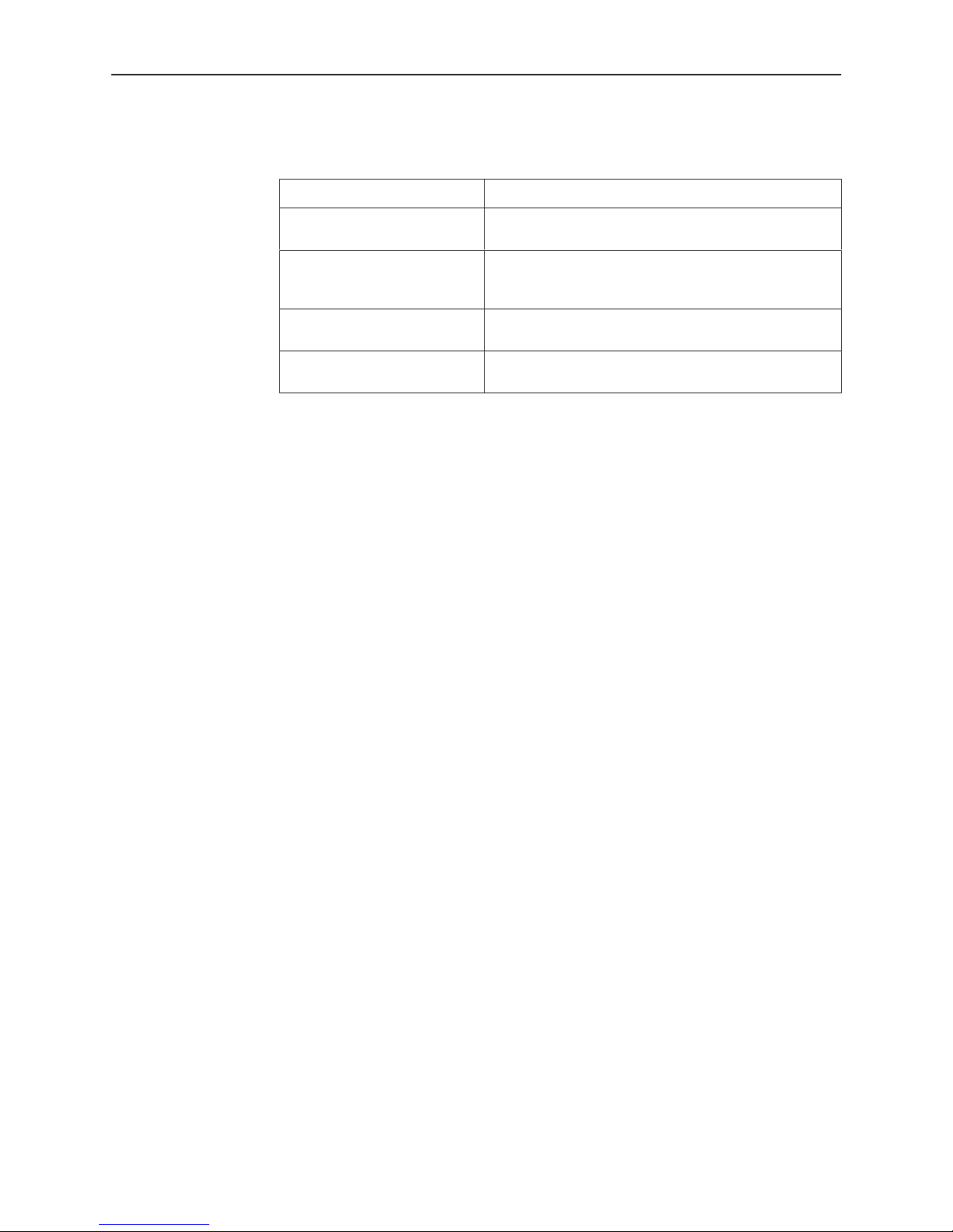
Cables and Equipment You May Need to Order
If connecting . . . Order a . . .
A VT100-compatible terminal
to the Terminal port
A PC to the Terminal port Standard straight-through EIA-232 cable with a DB25
An external modem to
Terminal port
A DTE with a V.35 connector
to the DTE port
Contact your sales or service representative to order these cables. For detailed
information, refer to Appendix E,
Guide.
Before Installation
Before installation, read the
Make sure you have:
- A dedicated, grounded ac outlet within 6 feet of the access unit that is
- A clean, well-lit, and ventilated site that is free from environmental extremes.
Standard straight-through EIA-232 cable with DB25
plug connectors on both ends.
plug connector on one end and a DB9 socket
connector on the other end.
Standard crossover EIA-232 cable with DB25 plug
connectors on both ends.
V.35 cable with an MS34 plug connector on one end
and an MS34 socket connector on the other end.
Important Safety Instructions
protected by a circuit breaker.
Cables and Pin Assignments,
on page 7.
in the User’s
- One to two feet of clearance for cable connections.
- An operable network connection.
- An operable LAN connection.
- A VT100-compatible asynchronous terminal or personal computer (PC)
Installing the DSU
" Procedure
To install the DSU:
1. Verify that you are installing the power supply provided with the DSU.
2. Plug the power supply module into an ac outlet.
3. Insert the 25-pin end of the EIA-232 cable into the TERMINAL port.
running terminal emulation software.
Insert the small power plug into the POWER jack.
2
December 1998
7612-A2-GN10-20
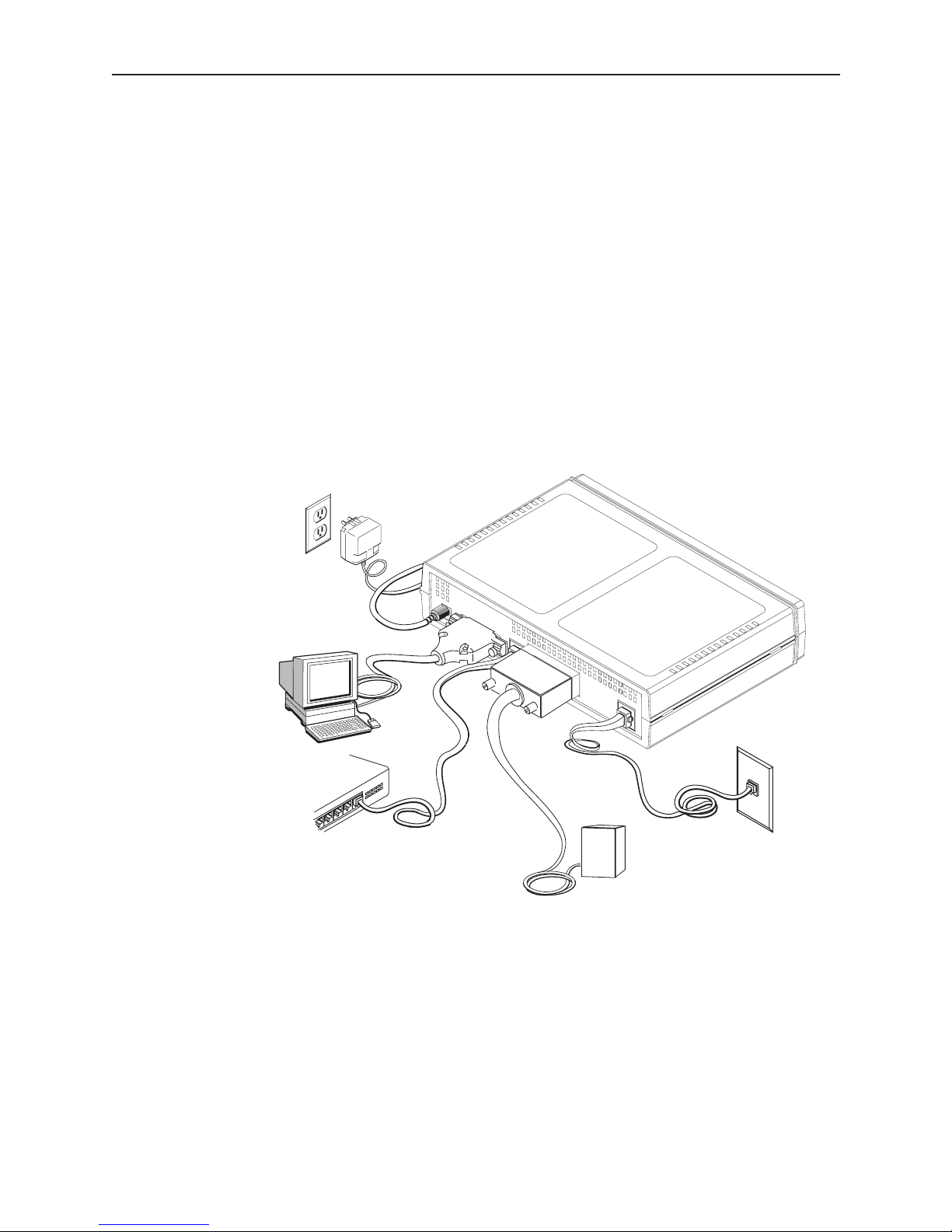
4. Insert the other end of the cable into the appropriate port of a
VT100-compatible terminal, PC, or modem.
The DSU has the factory-loaded set of VT100-compatible defaults for the
asynchronous terminal of 9.6 kbps, 8 bits per character, one stop bit, and no
parity.
5. Insert one unkeyed 8-pin connector on the Ethernet cable into the 10BaseT
port.
6. Insert the other end of the cable into the LAN interface.
7. Insert one end of the 34-pin V.35 cable into the DTE port.
8. Insert the other end of the V.35 cable into the DTE connector.
9. Insert the keyed 8-pin connector on the RJ48S network cable into the
NETWORK port.
10. Insert the other end of the cable into the RJ48S modular jack.
Power
Connection
POWER
Terminal
Connection
TERMINAL
10BaseT
D
T
E
NETWORK
RJ48S
Jack
LAN
DTE
Network
Connection
Connection
10BaseT
Connection
DTE
97-15310
CAUTION:
Use no power supply except the one provided with the DSU. Using the
wrong power supply can destroy the DSU.
7612-A2-GN10-20
December 1998
3
 Loading...