

Paradyne 7511 User Manual

MODEL 7511
DUAL DSU
USER’S GUIDE
Document No. 7511-A2-GB20-00
June 1997

Copyright 1997 Paradyne Corporation.
All rights reserved.
Printed in U.S.A.
Notice
This publication is protected by federal copyright law. No part of this publication may be copied or distributed,
transmitted, transcribed, stored in a retrieval system, or translated into any human or computer language in any form
or by any means, electronic, mechanical, magnetic, manual or otherwise, or disclosed to third parties without the
express written permission of Paradyne Corporation, 8545 126th Avenue North, P.O. Box 2826, Largo,
Florida 33779-2826.
Paradyne Corporation makes no representation or warranties with respect to the contents hereof and specifically
disclaims any implied warranties of merchantability or fitness for a particular purpose. Further, Paradyne Corporation
reserves the right to revise this publication and to make changes from time to time in the contents hereof without
obligation of Paradyne Corporation to notify any person of such revision or changes.
Changes and enhancements to the product and to the information herein will be documented and issued as a new
release to this manual.
Trademarks
All products and services mentioned herein are the trademarks, service marks, registered trademarks or registered
service marks of their respective owners.
Warranty, Sales, and Service Information
Contact your sales or service representative directly for any help needed. For additional information concerning
warranty, service, repair, spare parts, installation, documentation, or training, use one of the following methods:
Via the Internet: Visit the Paradyne World Wide W eb site at http://www.paradyne.com
Via Telephone: Call our automated call system to receive current information via fax or to speak with a
company representative.
— Within the U.S.A., call 1-800-870-2221
— International, call 727-530-2340
Printed on recycled paper
A
June 1997
7511-A2-GB20-00

Contents
About This Guide
Document Purpose and Intended Audience iii. . . . . . . . . . . . . . . . . . . . . . . . .
Document Summary iii. . . . . . . . . . . . . . . . . . . . . . . . . . . . . . . . . . . . . . . . . . . . .
Product-Related Documents iv. . . . . . . . . . . . . . . . . . . . . . . . . . . . . . . . . . . . . .
1 About the Dual DSU
Model 7511 Dual DSU Features 1-1. . . . . . . . . . . . . . . . . . . . . . . . . . . . . . . . . . .
DSU Configurations 1-2. . . . . . . . . . . . . . . . . . . . . . . . . . . . . . . . . . . . . . . . . . . . .
2 Configuring and Installing the DSUs
Configuring the Dual DSU 2-1. . . . . . . . . . . . . . . . . . . . . . . . . . . . . . . . . . . . . . . .
Installing the Rear Connector Plate 2-7. . . . . . . . . . . . . . . . . . . . . . . . . . . . . . . .
Installing the DSU Card 2-8. . . . . . . . . . . . . . . . . . . . . . . . . . . . . . . . . . . . . . . . . .
Installing the Network and DTE Cables 2-10. . . . . . . . . . . . . . . . . . . . . . . . . . . .
3 Monitoring the DSUs
Selecting a DSU 3-1. . . . . . . . . . . . . . . . . . . . . . . . . . . . . . . . . . . . . . . . . . . . . . . .
Front Panel LEDs 3-1. . . . . . . . . . . . . . . . . . . . . . . . . . . . . . . . . . . . . . . . . . . . . . .
Initialization 3-1. . . . . . . . . . . . . . . . . . . . . . . . . . . . . . . . . . . . . . . . . . . . . . . . .
LED Groups 3-1. . . . . . . . . . . . . . . . . . . . . . . . . . . . . . . . . . . . . . . . . . . . . . . .
Status LEDs 3-2. . . . . . . . . . . . . . . . . . . . . . . . . . . . . . . . . . . . . . . . . . . . . . . .
Network LEDs 3-3. . . . . . . . . . . . . . . . . . . . . . . . . . . . . . . . . . . . . . . . . . . . . .
DSU Selection LEDs 3-4. . . . . . . . . . . . . . . . . . . . . . . . . . . . . . . . . . . . . . . . .
T est 3-5. . . . . . . . . . . . . . . . . . . . . . . . . . . . . . . . . . . . . . . . . . . . . . . . . . . . . . . .
Port 3-6. . . . . . . . . . . . . . . . . . . . . . . . . . . . . . . . . . . . . . . . . . . . . . . . . . . . . . . .
4 T esting
Selecting a DSU 4-1. . . . . . . . . . . . . . . . . . . . . . . . . . . . . . . . . . . . . . . . . . . . . . . .
Local Loopback 4-1. . . . . . . . . . . . . . . . . . . . . . . . . . . . . . . . . . . . . . . . . . . . . . . . .
CSU or External Network Loopback 4-2. . . . . . . . . . . . . . . . . . . . . . . . . . . . . . .
Digital Loopback (DL) and Remote Loopback (RL) 4-3. . . . . . . . . . . . . . . . . .
Ending an Active Test 4-4. . . . . . . . . . . . . . . . . . . . . . . . . . . . . . . . . . . . . . . . . . . .
7511-A2-GB20-00
June 1997
i

Contents
5 Troubleshooting
Troubleshooting 5-1. . . . . . . . . . . . . . . . . . . . . . . . . . . . . . . . . . . . . . . . . . . . . . . . .
A Cables and Pin Assignments
Overview A-1. . . . . . . . . . . . . . . . . . . . . . . . . . . . . . . . . . . . . . . . . . . . . . . . . . . . . .
RJ48T 50-Pin Network Interface Connector A-1. . . . . . . . . . . . . . . . . . . . . . . . .
Digital Network (DDS) Connector A-2. . . . . . . . . . . . . . . . . . . . . . . . . . . . . . . . .
V.35 DTE Connector A-3. . . . . . . . . . . . . . . . . . . . . . . . . . . . . . . . . . . . . . . . . . . . .
B Technical Specifications
Glossary
Index
ii
June 1997
7511-A2-GB20-00

About This Guide
Document Purpose and Intended Audience
This guide contains information needed to set up, configure, and operate the
Model 7511 DSU and is intended for installers and operators.
Document Summary
Section Description
Chapter 1
Chapter 2
Chapter 3
Chapter 4
Chapter 5
Appendix A
Appendix B
Glossary Defines acronyms and terms used in this document.
Index Lists key terms, acronyms, concepts, and sections in
About the Dual DSU.
shows examples of typical configurations.
Configuring and Installing the DSUs.
for setting up and installing the DSU card.
Monitoring the DSUs.
the LEDs, DSU status, and network statistics.
Testing.
setup.
Troubleshooting.
troubleshooting.
Cables and Pin Assignments.
interface details.
Technical Specifications.
specifications of the DSU.
alphabetical order.
Provides details about available tests and test
Describes the DSU features and
Provides procedures
Describes monitoring details about
Provides information on device
Contains connector and
Contains physical and regulatory
7511-A2-GB20-00
June 1997
iii

About This Guide
Product-Related Documents
Document Number Document Title
3000-A2-GA31
3000-A2-GZ47
7511-A2-GN10
To order additional product documentation, refer to
Information
on page A at the beginning of this User’s Guide.
COMSPHERE 3000 Series Carrier
Installation Manual
Network Interface Cable, Network Interface Module
Installation
Model 7511 Dual DSU Startup Instructions
Warranty, Sales, and Service
iv
June 1997
7511-A2-GB20-00

About the Dual DSU
Model 7511 Dual DSU Features
The DSU provides an interface between the customer premises equipment (CPE)
and a Digital Data Service (DDS) network.
The DSU’s features and capabilities include:
Two DSUs on one card. Permits up to 32 DSUs in one 3000 Series carrier.
Easy Installation. Connects to your equipment using standard connectors
and cables.
1
Easy Configuration. Simple hardware strapping minimizes your
customization effort.
DDS Operation. Operates at 56 and 64 kbps CC (clear channel).
Local Area Data Set (LADS) Operation. Operates at 56 and 64 kbps
full-duplex as a limited-distance modem.
Diagnostics. Lets you diagnose device and network problems with digital
loopbacks and pattern tests.
Interoperability. Line-compatible with Model 3510, 3511, 3550, 3551, 3610,
3611, 3615, 3616, 7510, 7610 and 7612 DSUs on the DDS Primary Channel.
Reliability. The 7511 Dual DSU’s Mean Time Between Failures (MTBF) is
over 30 years.
7511-A2-GB20-00
June 1997
1-1
About the Dual DSU
0
2
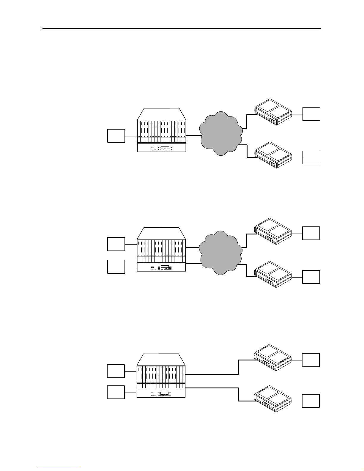
DSU Configurations
As shown in the following illustration, each DSU can be used in a multipoint
network configuration across a DDS network.
Model 7511 DSU
in 3000 Series Carrier
DTE
DSU
DSU
DTE
DDS
Network
DSUs can also be used for point-to-point DDS or frame relay applications.
Model 7511 DSU
in 3000 Series Carrier
DTE
DTE
Frame
Relay
Network
DSU
DSU
DTE
97-1550
DTE
DTE
97-1536
DSUs can be connected back-to-back to act as Local Area Data Sets. Table B-2
in Appendix B shows the maximum distances for LADS applications.
DTE
DTE
1-2
Model 7511 DSU
in 3000 Series Carrier
June 1997
56 or 64 Kbps
56 or 64 Kbps
DSU
DSU
7511-A2-GB20-00
DTE
DTE
97-15364
Configuring and Installing
the DSUs
Configuring the Dual DSU
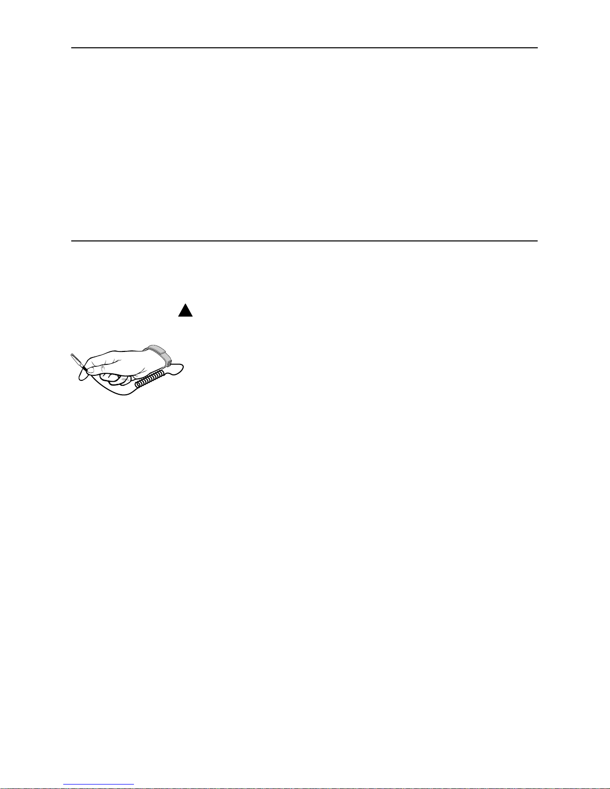
!
HANDLING PRECAUTIONS FOR
STATIC-SENSITIVE DEVICES
The Model 7511 Dual DSU is designed to protect sensitive components
from damage due to electrostatic discharge (ESD) during normal
operation. When performing installation procedures, however, take
proper static control precautions to prevent damage to equipment. If
496-15104
you are not sure of the proper static control precautions, contact your
nearest sales or service representative.
2
Procedure
To configure the Model 7511 Dual DSU:
1. Review Table 2-1 to determine the proper settings for your environment.
The first choice for each option (shown in boldface type) is the factory
default setting. If you choose the factory default value, you do not need to
change the position of the associated switch.
The factory default setting for all switches is Off.
2. Mark any options in the table that you wish to differ from the factory default.
3. Using Figure 2-1 and Table 2-1, verify that the switch settings for both DSUs
on the 7511 card match your selections.
Do not modify the settings of switches not listed in the table. Any switch
not designated for customer use should be in the Off position.
4. Where required, verify that the local and remote DSUs employ the same
options. For example, both the local and remote DSU must use the same
Line Rate and 64CC Data Scrambler settings.
7511-A2-GB20-00
June 1997
2-1
Configuring and Installing the DSUs
S1
8
7
6
5
4
3
2
1
ON
8
7
6
5
4
3
2
1
ON
S3
S2
S4
S5
8
7
6
5
4
3
2
1
ON
8
7
6
5
4
3
2
1
ON
8
7
6
5
4
3
2
1
ON
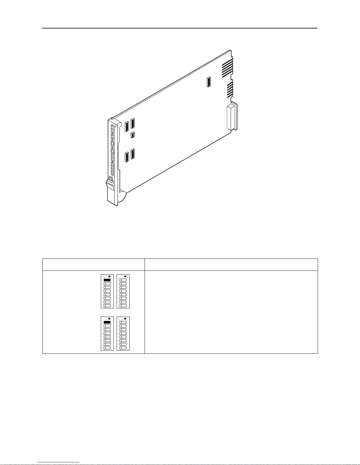
Figure 2-1. Model 7511 Switch Locations
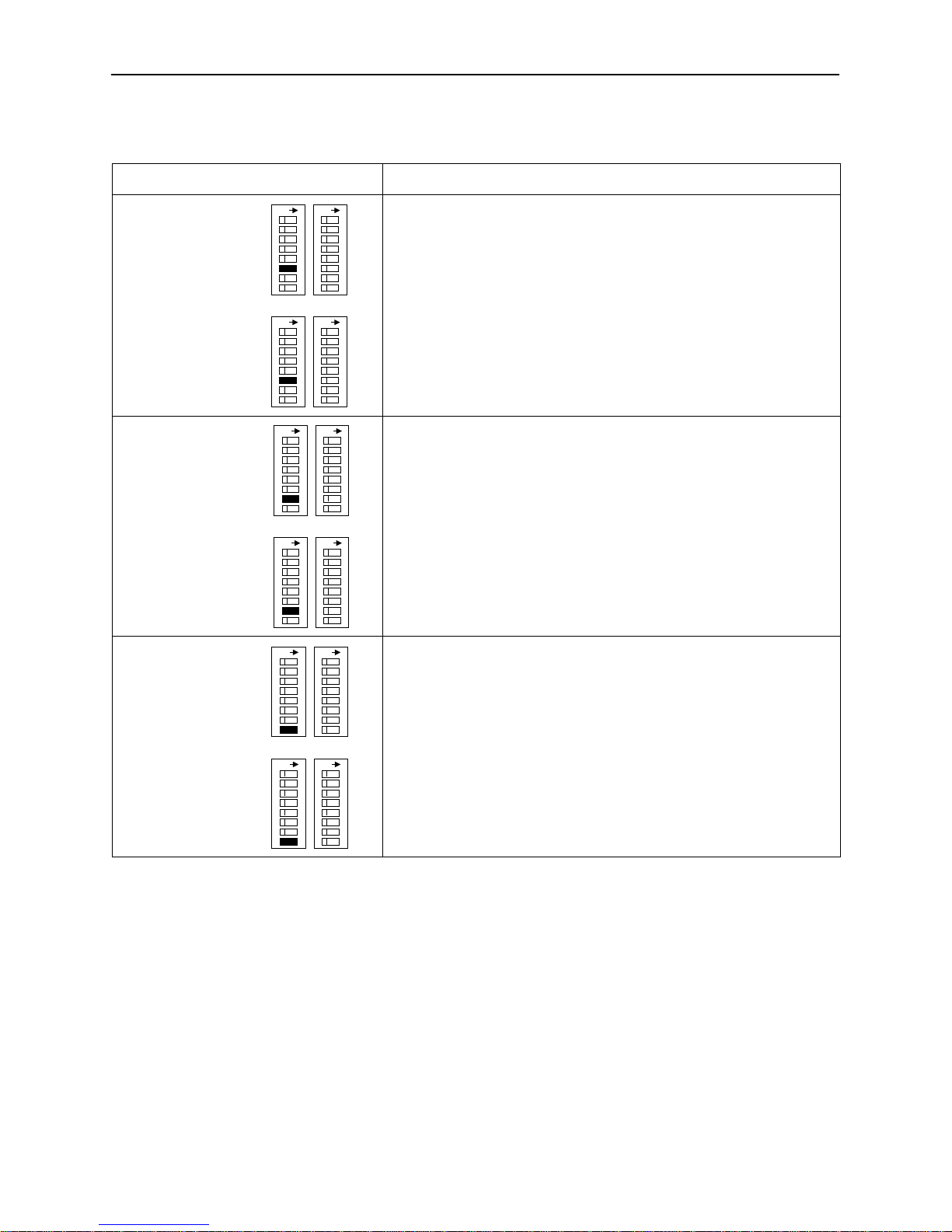
Table 2-1. Configuration Options (1 of 5)
Switch
Line Rate
S1-1 (DSU A)
S3-1 (DSU B)
ON ON
S1 S2
S3 S4
ON ON
DSU A
DSU B
97-15396
Options and Usage Default in Bold
DDS or LADS line rate.
Off 56 kbps
The line rate is 56 kbps.
ON 64 kbps
LADS: The line rate is 64 kbps.
DDS: The line rate is 64 kbps clear channel.
2-2
June 1997
7511-A2-GB20-00
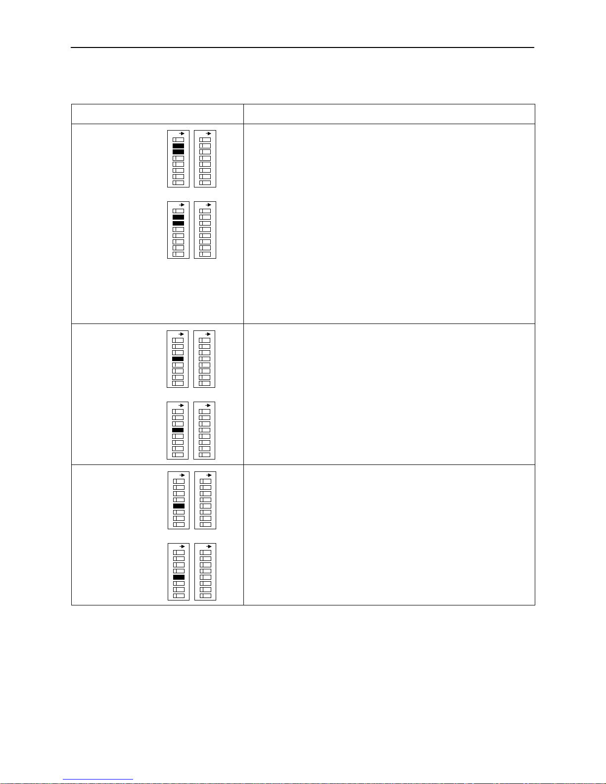
Table 2-1. Configuration Options (2 of 5)
Configuring and Installing the DSUs
Switch Options and Usage
TX Timing Source
S1-2 & S1-3 (DSU A)
S3-2 & S3-3 (DSU B)
T en-Minute Test
Abort Timer
S1-4 (DSU A)
S3-4 (DSU B)
ON ON
S1 S2
S3 S4
ON ON
ON ON
S1 S2
S3 S4
ON ON
The timing source for the DSU.
Off Off DDS
DSU A
For DDS, both switches must be Off.
For LADS:
Off ON Receive
Receive means timing is derived from the line receive signal.
DSU B
ON Off Internal
Internal means timing is provided by the unit’s internal clock.
ON ON External
External means timing is provided by the DTE.
Determines whether user-initiated tests automatically terminate after
10 minutes.
DSU A
Off Enable
Tests terminate automatically after 10 minutes.
ON Disable
Tests run indefinitely .
DSU B
Default in Bold
Network-Initiated
DSU Loopback
S1-5 (DSU A)
S3-5 (DSU B)
7511-A2-GB20-00
ON ON
S1 S2
S3 S4
ON ON
Determines whether the DSU responds to DSU latching loopback start
and stop sequences sent by the network. This option is applicable only
if the DDS line rate is 64 kbps clear channel.
DSU A
Off Enable
The DSU responds to loopback sequences.
ON Disable
DSU B
The DSU ignores loopback sequences.
June 1997
2-3
Configuring and Installing the DSUs
Table 2-1. Configuration Options (3 of 5)
Switch Options and Usage
64CC Data Scrambler
S1-6 (DSU A)
S3-6 (DSU B)
V.54 Sequence
Detection
S1-7 (DSU A)
S3-7 (DSU B)
ON ON
S1 S2
S3 S4
ON ON
ON ON
S1 S2
S3 S4
ON ON
Determines whether the DSU scrambles data to minimize the possibility
of the remote DSU falsely recognizing a loopback command.
DSU A
Off Disable
Data scrambling is disabled.
ON Enable
Data scrambling is enabled.
DSU B
Determines whether the DSU responds to V.54 Loop Up and Loop
Down sequences from the remote DSU.
DSU A
Off Disable
V.54 loop sequences are ignored.
ON Enable
The DSU responds to V.54 loop sequences.
DSU B
Default in Bold
Invert
TX Clock
S1-8 (DSU A)
S3-8 (DSU B)
ON ON
S1 S2
S3 S4
ON ON
Determines whether the DSU clock provided on interchange circuit
CT1 14 (TXC) is phase-inverted with respect to interchange circuit
CT103 (TXD). This can reduce errors encountered due to excessive
DSU A
cable lengths.
Off Normal
TXC is not inverted.
ON Invert
DSU B
TXC is inverted with respect to TXD.
2-4
June 1997
7511-A2-GB20-00
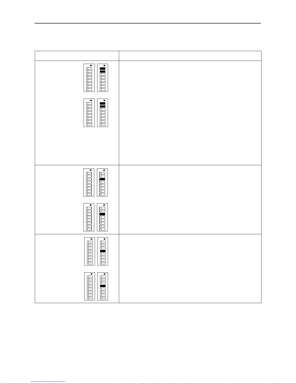
Table 2-1. Configuration Options (4 of 5)
Configuring and Installing the DSUs
Switch Options and Usage
CTS
S2-1 & S2-2 (DSU A)
S4-1 & S4-2 (DSU B)
RTS
S2-3 (DSU A)
S4-3 (DSU B)
ON ON
S1 S2
S3 S4
ON ON
ON ON
S1 S2
S3 S4
ON ON
Determines the operation of interchange circuit CT106, Clear to Send
(CTS).
DSU A
Off Off Standard
CTS follows RTS with a fixed delay except when an alarm is detected
or a test is active, when CTS is turned off.
Off ON Circuit Assurance
DSU B
Same as standard, but CTS is also turned off when Carrier Mode Idle
codes are received.
ON Off Follow RTS
CTS follows RTS without delay, regardless of alarms and tests.
ON ON Forced On
CTS is forced on after a successful self-test.
Determines the operation of interchange circuit CT105, Request to
Send (RTS).
DSU A
Off Constant
The internal RTS is forced on and the DSU is in a constant data mode.
The transmitted signal is either Data Mode Idle codes or DTE data.
ON Switched
DSU B
RTS is monitored, and Carrier Mode Idle codes are transmitted when
RTS is off.
Default in Bold
LSD
S2-4 (DSU A)
S4-4 (DSU B)
7511-A2-GB20-00
ON ON
S1 S2
S3 S4
ON ON
Determines the operation of interchange circuit CT109, Line Signal
Detect (LSD).
DSU A
Off Standard
LSD is on when the receive line is in data mode, and off when an alarm
is detected or Carrier Mode Idle codes are received.
ON Forced On
DSU B
LSD is forced on after a successful self-test.
June 1997
2-5
 Loading...