

Paradyne 7510 Supplementary Manual

TM
Model 7510 DSU
Startup Instructions
Document Number 7510-A2-GN10-30
January 1999
Product Documentation on the World Wide Web
We provide complete product documentation online. This lets you search the
documentation for specific topics and print only what you need, reducing the
waste of surplus printing. It also helps us maintain competitive prices for our
products.
Complete documentation for this product is available at www.paradyne.com.
Select
Devices.
Select the following document:
Service & Support → Technical Manuals → Subrate Digital Access
7510-A2-GB20
Model 7510 DSU User’s Guide
To request a paper copy of a Paradyne document:
Within the U.S.A., call 1-800-PARADYNE (1-800-727-2396)
Outside the U.S.A., call 1-727-530-8623
Cables You May Need to Order
The following table describes typical equipment. Identify the connectors required
for your equipment before you contact your sales or service representative to
order cables. For cable details, refer to Appendix C,
Assignments
If connecting . . .
A VT100-compatible terminal
to the Terminal port
A PC to the Terminal port Standard straight-through EIA-232 cable with a DB25
An External Modem to the
Terminal port
A DTE with a V.35 connector
to the DTE port
, in the User’s Guide.
Cables and Pin
Order a . . .
Standard straight-through EIA-232 cable with DB25
plug connectors on both ends.
plug connector on one end and a DB9 or DB25 socket
connector, as required, on the other end.
Standard crossover EIA-232 cable with DB25 plug
connectors on both ends.
V.35 cable with an MS34 plug connector on one end
and an MS34 socket connector on the other end.
7510-A2-GN10-30
January 1999
1

Package Checklist
Verify that your package contains the following:
- A Model 7510 DSU
- Power cord with power transformer
- RJ48S modular cable for U.S. network access (14)
No DTE cables are provided. Additional cables may need to be ordered; see
Cables You May Need to Order
Preparation
Make sure you have:
- A dedicated, grounded ac outlet that is protected by a circuit breaker within
- A clean, well-lit, and ventilated site that is free from environmental extremes.
- An operable network connection.
- A VT100-compatible asynchronous terminal or PC (personal computer)
on page 1.
6 feet of the access unit.
running terminal emulation software.
Before installing your DSU, read the
Installing the DSU
" Procedure
To install the DSU:
1. Plug the end of the power cord into the POWER jack on the DSU. Plug the
2. Plug the 8-pin connector on the RJ48S network cable into the NETWORK
3. Plug one end of the 34-pin V.35 cable into the DTE port of the DSU. Plug the
4. Plug the 25-pin end of an EIA-232 cable into the TERMINAL port of the DSU.
Important Safety Instructions
power transformer into an ac outlet.
on page 7.
CAUTION:
Use no power supply except the one provided with the DSU. Using the
wrong power supply can destroy the DSU.
connector on the DSU. Plug the other end of the cable into the RJ48S
modular jack.
other end of the V.35 cable into the DTE connector.
Plug the other end of the cable into the VT100-compatible user interface
connector.
2
January 1999
7510-A2-GN10-30
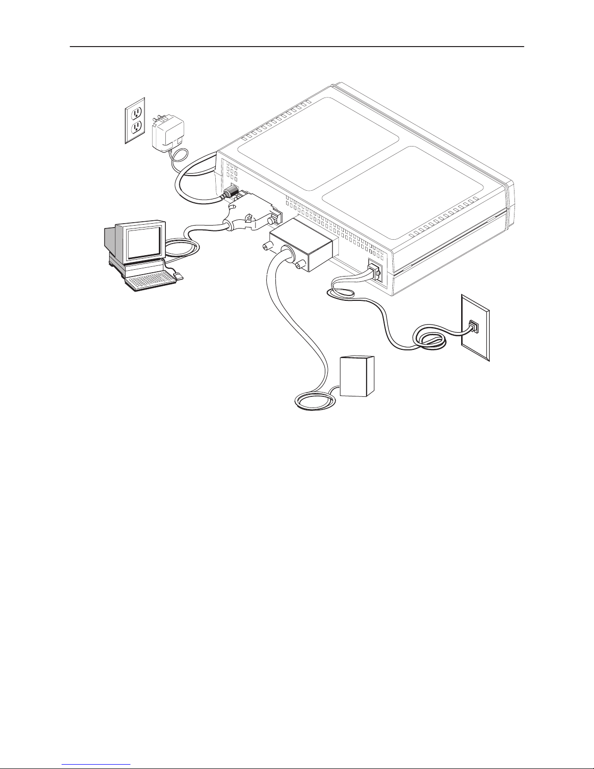
Terminal
Connection
Power
Connection
POWER
TERMINAL
D
T
E
DTE
Connection
DTE
NETWORK
Network
Connection
RJ48S
Jack
497-15240
NOTES:
Your terminal or PC software must be set to communicate at a rate of
9.6 kbps, using characters of 8 bits, one stop bit, and no parity.
If you connect an external modem instead of an asynchronous terminal or
PC:
— Use an EIA-232 crossover cable as described in Appendix C,
Pin Assignments,
in the User’s Guide.
— If possible, configure your modem to use standard RS232 detection and
control for CTS, DSR, DTR, LSD, and RTS.
— If possible, disable AT commands on your modem.
Cables and
7510-A2-GN10-30
January 1999
3
 Loading...