

Paradyne 7123 User Manual

7123 SNMP DSU/CSU
User’s Guide
Document No. 7123-A2-GB20-00
September 2001

Copyright © 2001 Paradyne Corporation
All rights reserved.
Printed in U.S.A.
Notice
This publication is protected by federal copyright law. No part of this publication may be copied or distributed,
transmitted, tr ansc ribed, store d in a re trie v al syst em, or tr ans lated into a n y huma n or com puter l anguag e in an y form or
by any means, electronic, mechanical , ma gne tic, manual or otherwise, or discl osed to third parties without the express
written permission of Paradyne Corporation, 8545 126th Ave. N., Largo, FL 33773.
Paradyne Corporation makes no representation or warranties with respect to the contents hereof and specifically
disclaims any implied warranties of merchantability or fitness for a particular purpose. Further, Paradyne Corporation
reserves the right to revise this publication and to make changes from time to time in the contents hereof without
obligation of Paradyne Corporation to notify any person of such revision or changes.
Changes and enhancements to the product and to the information herein will be documented and issued as a new
release to this manual.
Warranty, Sales, Service, and Training Information
Contact your local sale s representativ e, se rvice representativ e, or distrib utor directly f or any hel p needed. F or additional
information concerning warranty, sales, service, repair, installation, documentation, training, distributor locations, or
Paradyne worldwide office locations, use one of the following methods:
Internet:
www.paradyne.com/warranty
Telephone:
representative.
— Within the U.S.A., call 1-800-870-2221
— Outside the U.S.A., call 1-727-530-2340
Visit the Paradyne World Wide Web s i te at
.)
Call our automated system to receive current information by fax or to speak with a company
www.paradyne.com
. (Be sure to register your warranty at
Document Feedback
We welcome your comments and suggestions about this document. Please mail them to Technical Publications,
Paradyne Corporation, 8545 126th Ave. N., Largo, FL 33773, or send e-mail to
number and title of this document in your correspondence. Please include your name and phone number if you are
willing to provide additional clarification.
userdoc@paradyne.com
. Include the
Trademarks
ACCULINK, COMSPHERE, FrameSaver, Hotwire, MVL, NextEDGE, OpenLane, and Performance Wizard are
registered trademarks of Paradyne Corporation. ReachDSL and TruePut are trademarks of Paradyne Corporation. All
other products and s ervices m en tion ed here in are the trademarks, service marks, reg is tere d trademarks, or registered
service marks of their respective owners.
September 2001 7123-A2-GB20-00
A

Contents
About This Guide
Purpose and Intended Audience . . . . . . . . . . . . . . . . . . . . . . . . . . . . . v
Document Organization . . . . . . . . . . . . . . . . . . . . . . . . . . . . . . . . . . . . v
Product-Related Documents . . . . . . . . . . . . . . . . . . . . . . . . . . . . . . . . vi
Conventions Used . . . . . . . . . . . . . . . . . . . . . . . . . . . . . . . . . . . . . . . . vii
1 About the 7123 SNMP DSU/CSU
System Overview . . . . . . . . . . . . . . . . . . . . . . . . . . . . . . . . . . . . . . . . . 1-1
Differences Between 7112 and 7123 DSU/CSUs . . . . . . . . . . . . . . . . 1-2
2 User Interface and Basic Operation
Logging On. . . . . . . . . . . . . . . . . . . . . . . . . . . . . . . . . . . . . . . . . . . . . . 2-2
Main Menu . . . . . . . . . . . . . . . . . . . . . . . . . . . . . . . . . . . . . . . . . . . . . . 2-4
Screen Work Areas . . . . . . . . . . . . . . . . . . . . . . . . . . . . . . . . . . . . . . . 2-5
Navigating the Screens . . . . . . . . . . . . . . . . . . . . . . . . . . . . . . . . . . . . 2-6
Keyboard Keys . . . . . . . . . . . . . . . . . . . . . . . . . . . . . . . . . . . . . . . 2-6
Function Keys . . . . . . . . . . . . . . . . . . . . . . . . . . . . . . . . . . . . . . . . 2-7
Selecting from a Menu. . . . . . . . . . . . . . . . . . . . . . . . . . . . . . . . . . 2-8
Switching Between Screen Areas . . . . . . . . . . . . . . . . . . . . . . . . . 2-8
Selecting a Field . . . . . . . . . . . . . . . . . . . . . . . . . . . . . . . . . . . . . . 2-9
Entering Information . . . . . . . . . . . . . . . . . . . . . . . . . . . . . . . . . . . 2-9
3 Configuration
Basic Configuration . . . . . . . . . . . . . . . . . . . . . . . . . . . . . . . . . . . . . . . 3-2
Entering System Information and Setting the System Clock . . . . . . . . 3-7
Configuration Option Tables . . . . . . . . . . . . . . . . . . . . . . . . . . . . . . . . 3-8
Configuring the Overall System . . . . . . . . . . . . . . . . . . . . . . . . . . . . . . 3-9
7123-A2-GB20-00 Septem ber 200 1
Configuration Option Areas . . . . . . . . . . . . . . . . . . . . . . . . . . . . . . 3-3
Accessing and Displaying Configuration Options . . . . . . . . . . . . . 3-4
Changing Configuration Options . . . . . . . . . . . . . . . . . . . . . . . . . . 3-5
Saving Configuration Options . . . . . . . . . . . . . . . . . . . . . . . . . . . . 3-6
Configuring General System Options . . . . . . . . . . . . . . . . . . . . . . 3-9
i

Contents
Configuring the Physical Interfaces . . . . . . . . . . . . . . . . . . . . . . . . . . . 3-10
Configuring the Network Interface . . . . . . . . . . . . . . . . . . . . . . . . . 3-10
Configuring the User Data Port . . . . . . . . . . . . . . . . . . . . . . . . . . . 3-13
Assigning Time Slots/Cross Connections . . . . . . . . . . . . . . . . . . . . . . 3-16
Assigning the Synchronous Data Port to Network Time Slots. . . . 3-17
Clearing Assignments . . . . . . . . . . . . . . . . . . . . . . . . . . . . . . . . . . 3-18
Setting Up Management and Communication Options . . . . . . . . . . . . 3-19
Configuring Node IP Information . . . . . . . . . . . . . . . . . . . . . . . . . . 3-19
Configuring General SNMP Management . . . . . . . . . . . . . . . . . . . 3-21
Configuring Telnet and/or FTP Session Support. . . . . . . . . . . . . . 3-22
Configuring SNMP NMS Security . . . . . . . . . . . . . . . . . . . . . . . . . 3-25
Configuring SNMP Traps. . . . . . . . . . . . . . . . . . . . . . . . . . . . . . . . 3-27
Configuring the Ethernet Port . . . . . . . . . . . . . . . . . . . . . . . . . . . . 3-30
Configuring the Communication Port. . . . . . . . . . . . . . . . . . . . . . . 3-32
Configuring the COM Port to Support an External Modem . . . . . . 3-36
4 Security and Logins
Limiting Access . . . . . . . . . . . . . . . . . . . . . . . . . . . . . . . . . . . . . . . . . . 4-2
Controlling Asynchronous Terminal Access. . . . . . . . . . . . . . . . . . . . . 4-2
Controlling External COM Port Device Access . . . . . . . . . . . . . . . . . . 4-4
Controlling Telnet or FTP Access . . . . . . . . . . . . . . . . . . . . . . . . . . . . 4-4
Limiting Telnet Access. . . . . . . . . . . . . . . . . . . . . . . . . . . . . . . . . . 4-5
Limiting FTP Access . . . . . . . . . . . . . . . . . . . . . . . . . . . . . . . . . . . 4-6
Controlling SNMP Access . . . . . . . . . . . . . . . . . . . . . . . . . . . . . . . . . . 4-7
Disabling SNMP Access . . . . . . . . . . . . . . . . . . . . . . . . . . . . . . . . 4-7
Assigning SNMP Community Names and Access Levels . . . . . . . 4-8
Limiting SNMP Access through IP Addresses. . . . . . . . . . . . . . . . 4-9
Creating a Login. . . . . . . . . . . . . . . . . . . . . . . . . . . . . . . . . . . . . . . . . . 4-10
Modifying a Login. . . . . . . . . . . . . . . . . . . . . . . . . . . . . . . . . . . . . . . . . 4-11
Deleting a Login . . . . . . . . . . . . . . . . . . . . . . . . . . . . . . . . . . . . . . . . . . 4-11
5 Operation and Maintenance
Displaying System Information. . . . . . . . . . . . . . . . . . . . . . . . . . . . . . . 5-2
Viewing LEDs and Control Leads . . . . . . . . . . . . . . . . . . . . . . . . . . . . 5-3
LED Descriptions. . . . . . . . . . . . . . . . . . . . . . . . . . . . . . . . . . . . . . 5-4
Device Messages. . . . . . . . . . . . . . . . . . . . . . . . . . . . . . . . . . . . . . . . . 5-6
Status Information . . . . . . . . . . . . . . . . . . . . . . . . . . . . . . . . . . . . . . . . 5-10
System and Test Status Messages. . . . . . . . . . . . . . . . . . . . . . . . 5-11
Time Slot Assignment Status. . . . . . . . . . . . . . . . . . . . . . . . . . . . . 5-14
September 2001 7123-A2-GB20-00
ii

IP Routing Table . . . . . . . . . . . . . . . . . . . . . . . . . . . . . . . . . . . . . . . . . 5-15
Performance Statistics. . . . . . . . . . . . . . . . . . . . . . . . . . . . . . . . . . . . . 5-17
Clearing Performance Statistics . . . . . . . . . . . . . . . . . . . . . . . . . . 5-18
ESF Line Performance Statistics. . . . . . . . . . . . . . . . . . . . . . . . . . 5-19
Ethernet Performance Statistics . . . . . . . . . . . . . . . . . . . . . . . . . . 5-22
FTP File Transfers . . . . . . . . . . . . . . . . . . . . . . . . . . . . . . . . . . . . . . . . 5-23
Upgrading System Software . . . . . . . . . . . . . . . . . . . . . . . . . . . . . 5-25
Determining Whether a Download Is Complete. . . . . . . . . . . . . . . 5-26
Changing Software . . . . . . . . . . . . . . . . . . . . . . . . . . . . . . . . . . . . 5-26
6Troubleshooting
Problem Indicators . . . . . . . . . . . . . . . . . . . . . . . . . . . . . . . . . . . . . . . . 6-2
Resetting the Unit and Restoring Communication . . . . . . . . . . . . . . . . 6-3
Resetting the Unit from the Control Menu . . . . . . . . . . . . . . . . . . . 6-3
Resetting the Unit By Cycling the Power. . . . . . . . . . . . . . . . . . . . 6-3
Restoring Communication with an Improperly Configured Unit. . . 6-4
Alarms . . . . . . . . . . . . . . . . . . . . . . . . . . . . . . . . . . . . . . . . . . . . . . . . . 6-5
Troubleshooting Device Problems . . . . . . . . . . . . . . . . . . . . . . . . . . . . 6-8
Tests Available. . . . . . . . . . . . . . . . . . . . . . . . . . . . . . . . . . . . . . . . . . . 6-9
Test Timeout Feature . . . . . . . . . . . . . . . . . . . . . . . . . . . . . . . . . . 6-10
Starting and Stopping a Test . . . . . . . . . . . . . . . . . . . . . . . . . . . . . . . . 6-10
Aborting All Tests. . . . . . . . . . . . . . . . . . . . . . . . . . . . . . . . . . . . . . 6-11
Physical Tests . . . . . . . . . . . . . . . . . . . . . . . . . . . . . . . . . . . . . . . . . . . 6-12
Line Loopback . . . . . . . . . . . . . . . . . . . . . . . . . . . . . . . . . . . . . . . . 6-13
Payload Loopback . . . . . . . . . . . . . . . . . . . . . . . . . . . . . . . . . . . . . 6-14
Send Line Loopback . . . . . . . . . . . . . . . . . . . . . . . . . . . . . . . . . . . 6-15
Send and Monitor Pattern Tests . . . . . . . . . . . . . . . . . . . . . . . . . . 6-16
DTE Loopback. . . . . . . . . . . . . . . . . . . . . . . . . . . . . . . . . . . . . . . . 6-17
IP Ping Test . . . . . . . . . . . . . . . . . . . . . . . . . . . . . . . . . . . . . . . . . . . . . 6-18
Lamp Test . . . . . . . . . . . . . . . . . . . . . . . . . . . . . . . . . . . . . . . . . . . . . . 6-19
Contents
A Menu Hierarchy
Menus . . . . . . . . . . . . . . . . . . . . . . . . . . . . . . . . . . . . . . . . . . . . . . . . . A-1
7123-A2-GB20-00 Septem ber 200 1
iii

Contents
B SNMP MIBs and Traps
MIB Support . . . . . . . . . . . . . . . . . . . . . . . . . . . . . . . . . . . . . . . . . . . . . B-2
Downloading MIBs and SNMP Traps. . . . . . . . . . . . . . . . . . . . . . . . . . B-2
System Group (mib-2) . . . . . . . . . . . . . . . . . . . . . . . . . . . . . . . . . . . . . B-3
DSU/CSU’s sysDescr (system 1) . . . . . . . . . . . . . . . . . . . . . . . . . B-3
DSU/CSU’s sysObjectID (system 2) . . . . . . . . . . . . . . . . . . . . . . . B-3
Interfaces Group (mib-2) . . . . . . . . . . . . . . . . . . . . . . . . . . . . . . . . . . . B-4
Paradyne Indexes to the Interface Table (ifTable). . . . . . . . . . . . . B-4
Standards Compliance for SNMP Traps . . . . . . . . . . . . . . . . . . . . . . . B-4
Trap: warmStart. . . . . . . . . . . . . . . . . . . . . . . . . . . . . . . . . . . . . . . B-5
Trap: authenticationFailure . . . . . . . . . . . . . . . . . . . . . . . . . . . . . . B-5
Traps: linkUp and linkDown. . . . . . . . . . . . . . . . . . . . . . . . . . . . . . B-6
Traps: enterprise-Specific . . . . . . . . . . . . . . . . . . . . . . . . . . . . . . . B-9
Physical Interface Alarm Defaults . . . . . . . . . . . . . . . . . . . . . . . . . B-10
C Connectors, Cables, and Pin Assignments
Front Panel. . . . . . . . . . . . . . . . . . . . . . . . . . . . . . . . . . . . . . . . . . . . . . C-1
Rear Panel . . . . . . . . . . . . . . . . . . . . . . . . . . . . . . . . . . . . . . . . . . . . . . C-1
T1 Network Interface . . . . . . . . . . . . . . . . . . . . . . . . . . . . . . . . . . . . . . C-2
T1 Network Cable (Feature No. 3100-F1-500) . . . . . . . . . . . . . . . C-2
Canadian T1 Line Interface Cable (Feature No. 3100-F1-510). . . C-2
COM Port Connector . . . . . . . . . . . . . . . . . . . . . . . . . . . . . . . . . . . . . . C-3
Standard EIA-232-D Crossover Cable. . . . . . . . . . . . . . . . . . . . . . C-4
Configuring an External Modem . . . . . . . . . . . . . . . . . . . . . . . . . . C-5
Data Port Connector . . . . . . . . . . . . . . . . . . . . . . . . . . . . . . . . . . . . . . C-6
Standard V.35 Straight-through Cable. . . . . . . . . . . . . . . . . . . . . . C-6
Ethernet Port Connector . . . . . . . . . . . . . . . . . . . . . . . . . . . . . . . . . . . C-7
D Technical Specifications
E Equipment List
Equipment . . . . . . . . . . . . . . . . . . . . . . . . . . . . . . . . . . . . . . . . . . . . . . E-1
Cables . . . . . . . . . . . . . . . . . . . . . . . . . . . . . . . . . . . . . . . . . . . . . . . . . E-2
Index
September 2001 7123-A2-GB20-00
iv

About This Guide
Purpose and Intended Audience
This document contains information that applies to the 7123 SNMP DSU/CSU
unit. It is intended for system designers, engineers, administrators, and operators.
The reader should be familiar with the functional operation of digital data
communications equipment.
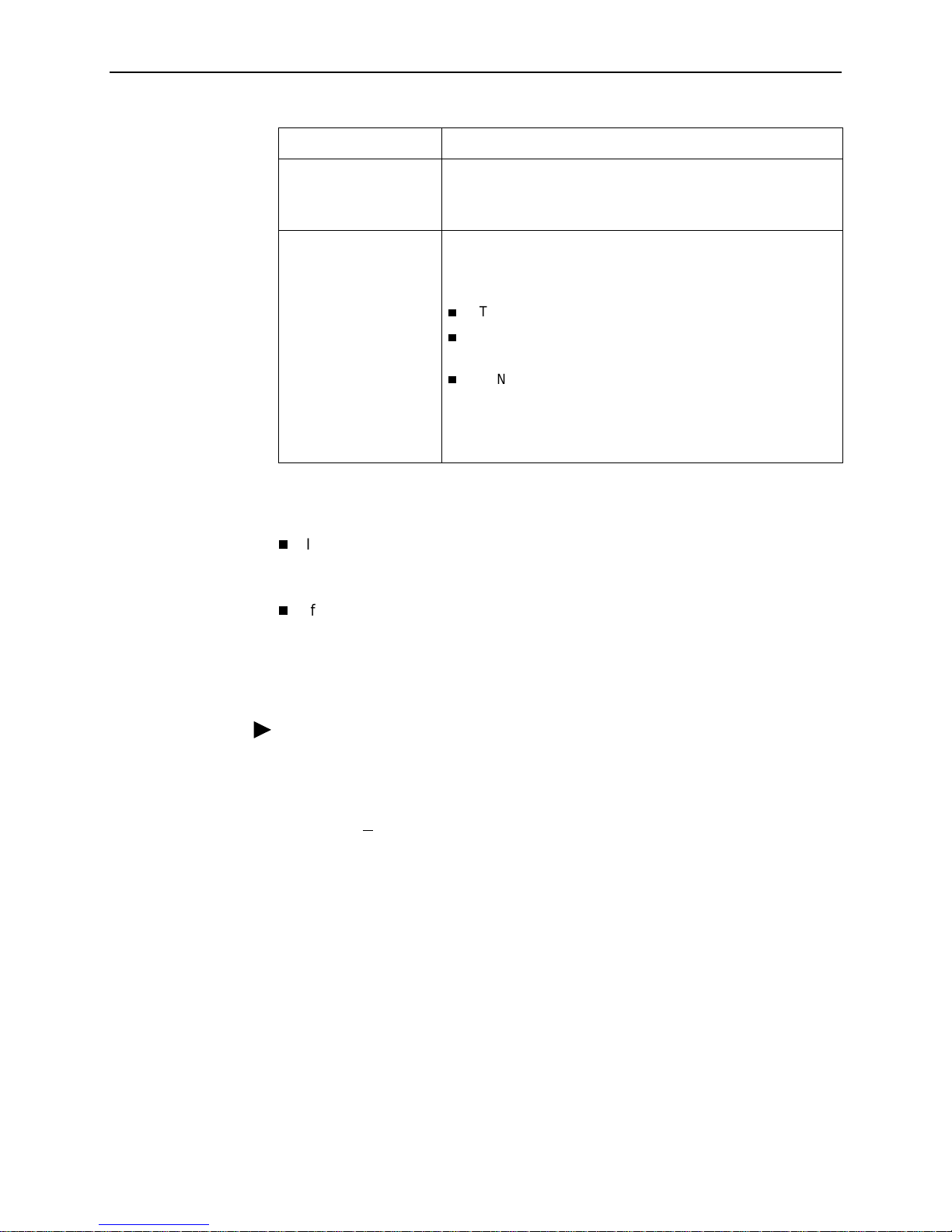
Document Organization
Section Description
Chapter 1,
DSU/CSU
Chapter 2,
Basic Operation
Chapter 3,
Chapter 4,
Chapter 5,
Maintenance
Chapter 6,
Appendix A,
Appendix B,
Traps
About the 7123 SNMP
User Interface and
Configuration
Security and Logins
Operation and
Troubleshooting
Menu Hierarchy
SNMP MIBs and
Describes some of the features of the 7123
DSU/CSU, including differences between it and the
7112 DSU/CSU.
Shows how to navigate the menu-driven user
interface.
Provides configuration information for the DSU/CSU.
Provides procedures for controlling access to the
DSU/CSU and setting up logins.
Provides procedures to display unit identification
information and pe rform file transfers, as well as how
to display and interpret status and statistical
information.
Provides dev ice pr ob lem res oluti on, alarm, and o ther
information, as well as troubleshooting and test
procedures.
Contains a graphical representation of how the user
interface screens are organized.
Identifies the MIBs suppor ted and how they can be
downloaded, describes the unit’s compliance with
SNMP format standards and with its special
operational trap features, and describes the alarm
and event defaults.
7123-A2-GB20-00 Septem ber 200 1
v

About This Guide
Section Description
Appendix C,
and Pin Assignments
Appendix D,
Specifications
Appendix E,
Index
Connectors, Cables,
Technical
Equipment List
A master glossary of terms and acronyms used in Paradyne documents is
available on the World Wide Web at
Technical Manuals →Technical Glossary
Product-Related Documents
Document Number Document Title
7123-A2-GN10
Shows the rear panel, tells what cables are needed,
and provides pin assignments for interfaces and
cables.
Technical Specifications.
Equipment List.
Lists key terms, acronyms, concepts, and sections.
www.paradyne .com
.
. Select
Library
7123 SNMP DSU/CSU Installation Instructions
→
Paradyne OpenLane SLM NMS Documentation:
7800-A2-GB30
7800-A2-GB31
OpenLane SLM Reports Reference Guide
OpenLane SLM Administrator’s Guide
Complete Paradyne documentation for this product is available at
www.paradyne .com
. Select
Library →Technical Manuals.
To order a paper copy of this manual:
Within the U.S.A., call 1-800-PARADYNE (1-800-727-2396)
Outside the U.S.A., call 1-727-530-8623
September 2001 7123-A2-GB20-00
vi

Conventions Used
Convention Used to . . .
About This Guide
Italic
Menu selection sequence Provide an abbreviated method for indicating the
(Path:) Provide a check point that coincides with the menu path
Bracke ts [ ] Indicate multiple se lec tio n choi ce s wh en m ul tiple options
Text highlight ed in blue Indicate a hyperli nk to additional inf ormation when vie wing
Indicate variable information (for example, Ntt)
selections to be made from a menu or selections from
within a menu before performing a procedural step.
For example,
Main Menu →Status →System and Test Status
that you should select Status from the Main Menu, then
select System and Test Status from the Status menu.
shown at the top of the screen. Always shown within
parentheses so yo u can v erify t hat you are ref erenc ing the
correct table (for example, Path: main/config/alarm).
can be displayed (for example, Clear [
Statistics).
this manual online. Click on the highlighted text.
Network/Port-1
.
indicates
]
7123-A2-GB20-00 Septem ber 200 1
vii

About This Guide
September 2001 7123-A2-GB20-00
viii

About the 7123 SNMP DSU/CSU
System Overview
The 7123 SNMP DSU/CSU provides an interface between the T1 digital network
and the customer premises equipment, converting signals received from the DTE
(Data Terminal Equipment) to bipolar signals that can be transmitted over T1 lines.
The 7123 SNMP DSU/CSU offers these features:
Auto-Sensing 10/100BaseT Port.
an Ethernet LAN.
SNMP (Simple Network Management Protocol) Management.
network management via an industry-standard SNMP management system.
1
Allows the DSU/CSU to connect directly to
Provides
ASCII Terminal Interface.
interface for configuring and managing the DSU/CSU locally or remotely by
Telnet session or External Modem.
Two Customer-Specified Configuration Storage Areas.
access to alternate sets of configuration options.
Dual Flash Memory.
running. Two software loads can be stored and implemented at the user’s
discretion.
Testing Capability.
and network problems. Tests can be commanded from the unit’s menu-driven
user interface or the OpenLane SLM system.
IP Routing Table.
as well as host routes, the number of hops to the destination, the method by
which the route was added to the table, the interface used to get to the
destination, and how long the route has been in existence.
Provides a variety of tests to identify and diagnose device
Shows the IP routing table for the DSU/CSU, with network
Provides a menu-driven VT100-compatible
Allows quick
Allows software upgrades while the unit is up and
7123-A2-GB20-00 Septem ber 200 1
1-1

1. About the 7123 SNMP DSU /CSU
Differences Between 7112 and 7123 DSU/CSUs
If you have both models in your network, you should be aware that the 7112
DSU/CSU and 7123 DSU/CSU provide the same basic functions, but are based
on different hardware platforms. The following table shows the major differences.
Feature 7112 7123
COM Port Default Data
Rate
Data Port LEDs TXT, RXD, RTS, CTS, DTR TXT, RXD, RTS, DTR
Data Port Tests Data Terminal (DTE)
DS0 Assignment by Block
or ACAMI
FDL (Facili ty Data Link) f or
Remote Management
Front Panel Monitor Jacks Yes No
FTP Software and
Configuration File Transfer
IP Ping No Yes
IP Routing Table Display No Yes
Management Protocol
Statistics
Repeater Loopback
Network Test
9.6 Kbps 19.2 Kbps
DTE Loopback
Loopback and Data
Channel Loopback, Send
V.54 and Send FT1
Loopbacks, Pattern Tests
Yes No
Yes No
No Yes
Yes No
Yes No
Software Upgrades No Two software versions can
September 2001 7123-A2-GB20-00
1-2
be stored and activated

User Interface and Basic Operation
This chapter tells you how to access, use, and navigate the menu-driven user
interface. It includes the following:
Logging On
Main Menu
Screen Work Areas
Navigating the Screens
Keyboard Keys
—
Function Keys
—
on page 2-2
on page 2-4
on page 2-5
on page 2-6
2
Selecting from a Menu
—
Switching Between Screen Areas
—
Selecting a Field
—
Entering Information
—
What appears on the screens depends on:
Current configuration
Security access level
each user.
Data selection criteria
– How your network is currently configured.
– The security level set by the system ad minis tr ator for
– What you entered in previous screens.
7123-A2-GB20-00 Septem ber 200 1
2-1

2. User Interface and Basic Operation
Logging On
Start a session using one of the following methods:
Telnet session via the Ethernet port.
Dial-in connection using an external modem.
Direct terminal connection over the COM port.
When logging on, the User Interface Idle screen appears.
If no security was set up or security was disabled, the Main Menu screen
appears (see
If security was set up and is enabled, you are prompted for a login. Enter your
login ID and password.
When the user interface has been idle, a session is automatically ended and the
screen goes blank when the unit times out. Press Enter to reactivate the interface.
Procedure
Main Menu
on page 2-4). You can begin your session.
To log in when security is being enforced:
1. Type your assigned Login ID and press Enter.
2. Type your Password and press Enter.
— Valid characters – All printable ASCII characters
— Number of characters – Up to 10 characters can be entered in the Login
ID and Password fields
— Case-sensitive – Yes
An asterisk (*) appears in the password field for each character entered.
September 2001 7123-A2-GB20-00
2-2
If your login was . . . Then the . . .
2. User Interface and Basic Operation
Valid
Invalid Message,
Main Menu
NOTE:
currently active sessions.
Login screen is redisplayed.
After three unsuccessful attempts:
A Telnet session is closed.
The User Interface Idle screen appears for a directly
connected terminal or modem.
An SNMP trap is generated.
Access is denied.
See your system administrator to verify your login (Login
ID/Password combination).
appears. Begin your session.
If your lo gin i s valid, but access is d eni ed , t here a r e two
Invalid Password
, appears on line24, and the
The 7123 DSU/CSU supports two simultaneous sessions. If two sessions are
currently active, wait and try again.
If two sessions are currently active and you are attempting to access the unit
through Telnet, the local Telnet client process returns a
refused:
If two sessions are currently active and you are attempting to access the unit
message at the bottom of the screen.
Connection
over the COM port (using a terminal or external modem, not via Telnet), the
User Interface Already In Use screen is redisplayed. In addition, the type of
connection (Telnet Connection or Direct COM Port Connection) for each
current user is identified, along with the user’s login ID.
Procedure
To end the session:
1. Press Ctrl-a to switch to the function keys area of the screen.
2. Type e (E
— For a terminal-connected to the COM port, the session is ended.
— For a modem connected to the COM port, the session is ended and the
— For a Telnet connection, the session is closed and, if no other Telnet or
If ending a session from the Configuration branch, see
Options
xit) and press Enter.
modem is disconnected.
FTP session is occurring over the connection, the modem is
disconnected.
Saving Configuration
in Chapter 3,
Configuration
.
7123-A2-GB20-00 Septem ber 200 1
2-3

2. User Interface and Basic Operation
Main Menu
Entry to all of the DSU/CSU’s tasks begins at the Main Menu, which has several
menus or branches.
Access Level appears at the top of the screen if security has been set up.
main Access Level: 1 7123
Device Name: Node A 09/09/2001 02:01
MAIN MENU
Status
Test
Configuration
Control
------------------------------------------------------------------------------Ctrl-a to access these functions E
Select . . . To . . .
Status View diagnostic tests, interfaces, and statistics. You can also
display LEDs and DSU/CSU identity information.
Test Select and cancel tests for the DSU/CSU’s interfaces.
Configuration Display and edit the configuration options.
Control Control the menu-driven user interface, device naming, login
administration, and selecting software releases. You can also
initiate a power-on reset of the DSU/CSU.
See Appendix A,
Menu Hierarchy
, for a pictorial view of the menu hierarchy, which
represents the organization of the DSU/CSU’s menus and screens.
xit
September 2001 7123-A2-GB20-00
2-4
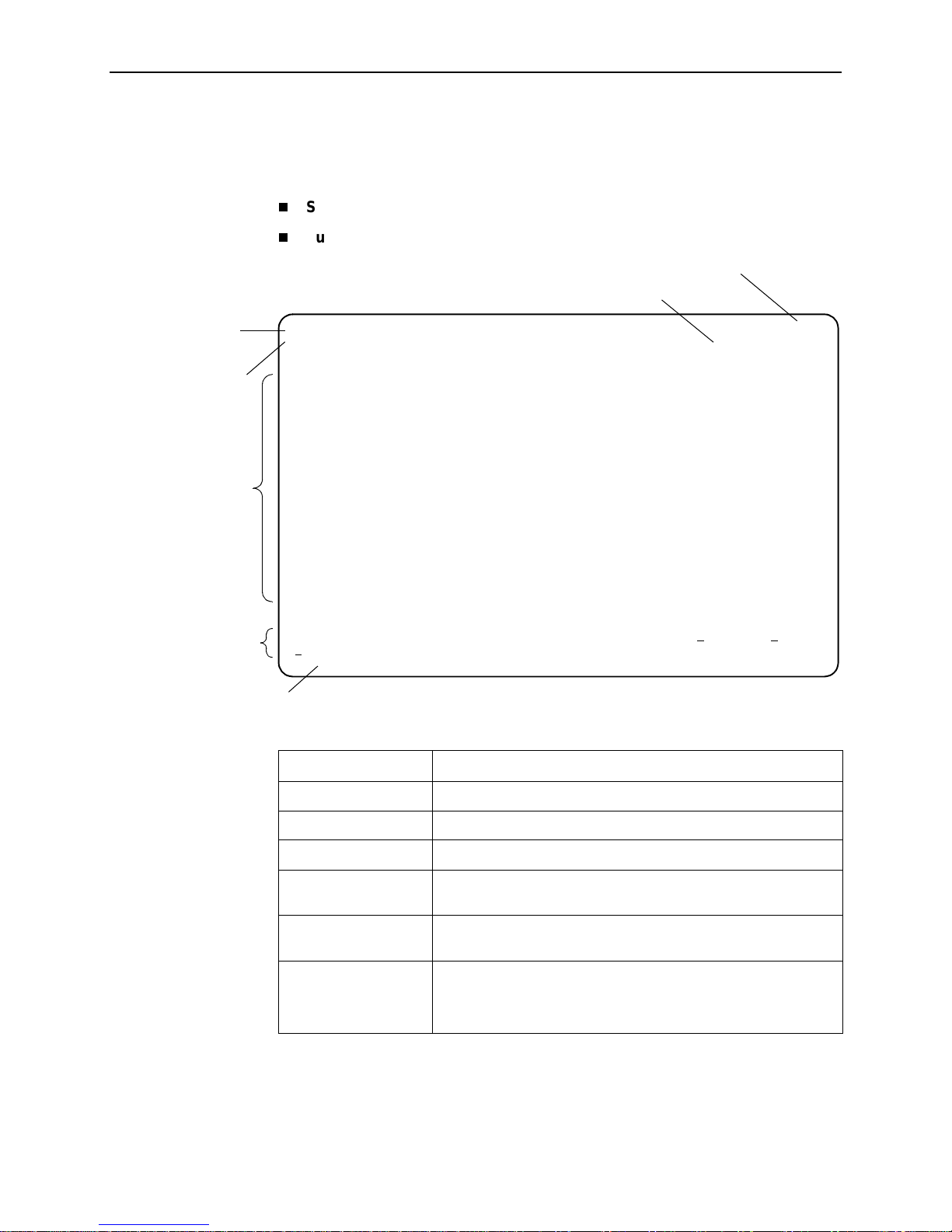
Screen Work Areas
There are two user work areas:
Screen area
– Where you input information into fields.
Function keys area
2. User Interface and Basic Operation
– Where you perform specific screen functions.
Model Number
Date and Time
Menu Path
Device Name
Screen Area
Function Keys Area
Message Area
main/config 7123
Device Name: Node A 09/09/2001 02:02
CONFIGURATION EDIT/DISPLAY
System
Network
Data Ports
Time Slot Assignment
Management and Communication
-------------------------------------------------------------------------------Ctrl-a to access these functions, ESC for previous menu MainMenu Exit
Save
Screen Format Description
Menu Path Menu selections made to reach the current screen.
Device Name Customer-assigned identification of the DSU/CSU.
7123 The DSU/CSU’s model number.
Screen Area Selection, displa y, and input fi elds f or monitoring an d maintaining
Function Keys Area Specific functions tha t ca n be performed by pressing a specifi ed
Message Area System-related information and valid settings for input fields in
7123-A2-GB20-00 Septem ber 200 1
the DSU/CSU.
key, then pressing Enter.
the lower left corner.
System and Test Status messages in the lower right cor ner.
2-5

2. User Interface and Basic Operation
Navigating the Screens
You can navigate the screens by:
Using keyboard keys.
Switching between the two screen work areas using function keys.
Keyboard Keys
Use the following keyboard keys to navigate within the screen area:
Press . . . To . . .
Ctrl-a Move cursor between the screen area and the
Esc Return to the previous screen.
screen function keys area.
Right Arrow (on same screen row), or
Tab (on any screen row)
Left Arrow (on same screen row), or
Ctrl-k
Backspace Move cursor one position to the left or to the last
Spacebar Select the next valid value for the field.
Delete (Del) Delete character that the cursor is on.
Up Arrow or Ctrl-u Move cursor up one field within a column on the
Down Arrow or Ctrl-d Move cursor down one field within a column on
Right Arrow or Ctrl-f Move cursor one character to the right if in edit
Left Arrow or Ctrl-b Move cursor one character to the left if in edit
Ctrl-l Redraw the screen display, clearing infor mation
Enter (Return) Accept entry or, when pressed before entering
Move cursor to the next field.
Move cursor to the previous field.
character of the previous field.
same screen.
the same screen.
mode.
mode.
typed in but not yet entered.
data or after entering invalid data, display valid
options on the last row of the screen.
September 2001 7123-A2-GB20-00
2-6
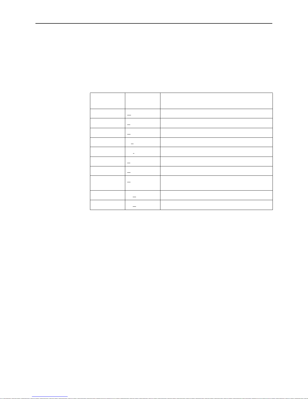
Function Keys
2. User Interface and Basic Operation
All function keys (located in the lower part of the screen; see the example in
Screen Work Areas
on page 2-5) operate the same way throughout the screens.
They are not case-sensitive, so upper- or lowercase letters can be used
interchangeably.
These keys use the following conventions:
For the screen
Select . . .
M or m MainMenu Return to the Main Menu screen.
function . . . And press Enter to . . .
E or e E
N or n New Enter new data.
O or o Mo
L or l Del
S or s Save Save information.
R or r R
C or c C
U or u PgUp Display the previous page.
D or d PgDn Display the next page.
xit Terminate the menu-driven user interface session.
dify Modify existing data.
ete Delete data.
efresh Update screen with current information.
lrStats Clear network performance statistics and refresh the
screen.
7123-A2-GB20-00 Septem ber 200 1
2-7

2. User Interface and Basic Operation
Selecting from a Menu
Procedure
To select from a menu:
1. Tab or press the down arrow key
selection, or press the up arrow key
menu list.
Each menu selection is highlighted as you press the key to move the cursor
from position to position.
2. Press Enter. The selected menu or screen appears.
Procedure
To return to a previous screen, press the Escape (Esc) key until you reach the
desired scr een.
Switching Between Screen Areas
Use Ctrl-a to switch between screen areas (see
Procedure
To switch to the function keys area:
1. Press Ctrl-a to switch from the screen area to the function keys area.
(↓)
to position the cursor on a menu
(↑)
to move the cursor to the bottom of the
Screen Work Areas
on page 2-5) .
2. Select either the function’s designated (underlined) character or Tab to the
desired function key.
3. Press Enter. The function is performed.
To return to the screen area, press Ctrl-a again.
September 2001 7123-A2-GB20-00
2-8

Selecting a Field
Entering Information
2. User Interface and Basic Operation
Once you reach the desired menu or screen, select a field to view or change, or
issue a command.
Press the Tab or right arrow key to move the cursor from one field to another. The
current setting or value appears to the right of the field.
You can enter information in one of three ways. Select the field, then:
Manually type in (enter) the field value or command.
Example:
Entering
admin
as a user’s Login ID on the Administer Logins screen (fro m
the Control menu/branch).
Type in (enter) the first letter(s) of a field value or command, using the unit’s
character-matching feature.
Example:
When configuring a port’s physical characteristic s with the Port (DTE) Initiated
Loopbacks configuration option/field selected (possible settings include
Disable, Local, DTPLB, DCLB, and Both), entering d or D displays the first
dt
value starting with d – Disable. In this example, entering
or
DT
would
display DTPLB as the selection.
Switch to the function keys area and select or enter a designated function key.
Example:
To save a configuration option change, select Save. S or s is the designated
function key.
If a field is blank and the Message area displays valid selections, press the
spacebar; the first valid setting for the field appears. Continue pressing the
spacebar to scroll through other possible settings.
7123-A2-GB20-00 Septem ber 200 1
2-9

2. User Interface and Basic Operation
September 2001 7123-A2-GB20-00
2-10

Configuration
This chapter includes the following:
Basic Configuration
Configuration Option Areas
—
Accessing and Displaying Configuratio n Options
—
Changing Configuration Options
—
Saving Configuration Options
—
Entering System Information and Setting the System Clock
on page 3-2
3
on page 3-7
Entering System Information and Setting the System Clock
Configuration Option Tables
Configuring the Overall System
Configuring the Physical Interfaces
Configuring the Network Interface
—
Configuring the User Data Port
—
Assigning Time Slots/Cross Connections
Assigning the Synchronous Data Port to Network Time Slots
—
Clearing Assignments
—
Setting Up Management and Communication Options
Configuring Node IP Information
—
Configuring General SNMP Management
—
Configuring Telnet and/or FTP Session Support
—
Configuring SNMP NMS Security
—
Configuring SNMP Traps
—
on page 3-8
on page 3-9
on page 3-10
on page 3-16
on page 3-7
on page 3-19
—
—
—
7123-A2-GB20-00 Septem ber 200 1
Configuring the Ethernet Port
Configuring the Communication Port
Configuring the COM Port to Support an External Modem
3-1

3. Configuration
Basic Configuration
Configuration option settings determine how the 7123 SNMP DSU/CSU operates.
Use the DSU/CSU’s Configuration Edit/Display menu to display or change
configuration option settings.
The Configuration Edit/Display menu of the 7123 DSU/CSU is shown below.
Configuration Menu
main/config 7123
Device Name: Node A 09/09/2001 03:01
CONFIGURATION EDIT/DISPLAY
System
Network
Data Ports
Time Slot Assignment
Management and Communication
-------------------------------------------------------------------------------Ctrl-a to access these functions, ESC for previous menu MainMenu Exit
Save
September 2001 7123-A2-GB20-00
3-2

Configuration Option Areas
The DSU/CSU arrives with configured factory default settings, which are located in
the Factory Default Configuration option area. You can find the default settings for
configuration options in the
If the factory default settings do not support your network’s configuration, you can
customize the configuration options to better suit your application.
Four configuration option storage areas are available:
Configuration Option Area Description
Current Configuration The currently active set of configuration options.
Customer Configuration 1 An alternate set of configuration options that the
Customer Configuration 2 Another alternate set of configuration options that the
Default Factory Configuration A read-only configuration area containing the factory
3. Configuration
Configuration Option Tables
customer can set up and store for future use.
customer can set up and store for future use.
default set of configuration options.
You can load and edit default factor y configuration
settings, but you can only save those changes to the
Current, Customer 1, or Customer 2 configuration option
areas.
The Current, Customer 1, and Customer 2 configuration
option areas are identical to the Default Factory
Configuration until modified by the customer.
on page 3-8.
7123-A2-GB20-00 Septem ber 200 1
3-3

3. Configuration
Accessing and Displaying Configuration Options
To access and display configuration options, load (copy) the applicable
configuration option set into the edit area.
Procedure
To load a set of configuration options for editing:
1. From the Main Menu, press the down arrow key
Configuration.
(↓)
so the cursor is on
2. Press Enter to display the Configuration menu. The
From:
menu appears.
Load Configuration
3. Select the configuration option area from which you want to load configuration
options and press Enter (Current Configuration, Customer Configuration 1,
Customer Configuration 2, or Default Factory Configuration).
The selected set of configuration options is loaded into the configuration edit
area and the
Configuration Edit/Display
menu appears.
This sequence of steps would be shown as the menu selection sequence:
Main Menu→Configuration
September 2001 7123-A2-GB20-00
3-4

Changing Configuration Options
Procedure
To change configuration option settings:
3. Configuration
1. From the
options and press Enter.
Configuration Edit/Display
For example:
menu, select a set of configuration
Configuration→Data Ports
2. Select the configuration options that are applicable to your network, and make
appropriate changes to the setting(s). See Chapter 2,
Basic Operation
3. Repeat Steps 1 and 2 until all changes are complete.
, for additional information.
User Interface and
NOTE:
— Only Security Access Level 1 users can change configuration options.
— Security Access Level 2 users can only view configuration options and run
tests.
— Security Access Level 3 users can only view configuration options; they
cannot change configuration options or run tests.
7123-A2-GB20-00 Septem ber 200 1
3-5

3. Configuration
Saving Configuration Options
When changes to the configuration options are complete, use the Save function
key to save your changes to either the Current, Customer 1, or Customer 2
configuration areas.
NOTE:
When changing settings, you must Save for changes to take effect.
Procedure
To save the configuration option changes:
1. Press Ctrl-a to switch to the function key area at the bottom of the screen.
2. Type s or S to select the S
Save Configuration To:
The
ave function and press Enter.
screen appears.
NOTE:
If you try to exit the Configuration menu without saving changes, a Save
Configuration screen appears requiring a Yes or No response.
— If you select N
are not saved.
— If you select Y
3. Select the configuration option area to which you want to save your changes
(usually the Current Configuration) and press Enter.
When Save is complete,
at the bottom of the screen.
o, the Main Menu screen reappears and the changes
es, the
Save Configuration To:
Command Complete
screen appears.
appears in the message area
NOTE:
There are other methods of changing configurations, like SNMP and
Auto-Configuration. Since multiple sessions can be active at the same
time, the last change made overwrites any previous or current changes
being made. For instance:
— Saving your configuration changes would cause configuration
changes made via another method to be lost.
September 2001 7123-A2-GB20-00
3-6
— If you are making changes and someone else makes changes and
saves them, your changes would be lost.

Entering System Information and Setting the System Clock
Select System Information to set up or display the general SNMP name for the
unit, its location, and a contact for the unit, as well as to set the system clock.
Main Menu→Control→System Information
The following information is available for viewing. Save any entries or changes.
If the selection is . . . Enter the . . .
Device Name Unique name for device identification of up to 20 characters.
System Name SNMP system name; can be up to 255characters.
System Location System’s physical location; can be up to 255 characters.
System Contact Name and how to contact the system person; can be up to
255 characters.
Date Current date in the month/day/year format (mm/dd/yyyy).
3. Configuration
Time Current time in
the hours:minutes format (hh:mm).
NOTE:
To clear existing information, place the cursor in the Clear field (Tab to the
Clear field) and press Enter.
See Chapter 4,
Security and Logins,
to set up and administer logins.
7123-A2-GB20-00 Septem ber 200 1
3-7

3. Configuration
Configuration Option Tables
Configuration option descriptions contained in this chapter are in menu order, even
though this may not be the order in which you access each when configuring the
unit.
The following configuration option tables are included:
Table 3-1, General System Options
Table 3-2, Network Physical Interface Options
Table 3-3, Data Port Physical Interface Options
Table 3-4, Node IP Options
Table 3-5, General SNMP Management Options
Table 3-6, Telnet and FTP Session Options
Table 3-7, SNMP NMS Security Options
Table 3-8, SNMP Traps Options
Table 3-9, Ethernet Management Options
Table 3-10, Communication Port Options
Table 3-11, External Modem (COM Port) Options
September 2001 7123-A2-GB20-00
3-8
 Loading...