

Paradyne 7112, 7112 T1 SNMP CSU Instructions Manual

Model 7112 T1 SNMP DSU/CSU
Startup Instructions
Document Number 7112-A2-GN10-40
February 2000
Product Documentation on the World Wide Web
We provide complete product documentation online. This lets you search the
documentation for specific topics and print only what you need, reducing the
waste of surplus printing. It also helps us maintain competitive prices for our
products.
Complete documentation for this product is available at www.paradyne.com.
Select Library → Technical Manuals → Subrate Digital Access Devices.
Select the following document:
7112-A2-GB20
Model 7112 T1 DSU/CSU, with Internal Ethernet LAN Adapter, User’s Guide
To request a paper copy of a Paradyne document:
H Within the U.S.A., call 1-800-PARADYNE (1-800-727-2396)
H Outside the U.S.A., call 1-727-530-8623
Package Checklist
Verify that your package contains the following in addition to the startup
instructions:
- A Model 7112 T1 DSU/CSU
- Wall-mount ac adapter
- One RJ48C unkeyed modular cable for T1 network
- One 8-position unkeyed modular cable for Ethernet LAN access
7112-A2-GN10-40
February 2000
1

Cables You May Need to Order
If connecting . . . Order a . . .
A VT100-compatible terminal
to the Terminal port
A PC to the Terminal port Standard straight-through EIA-232 cable with a DB25
An External Modem to the
Terminal port
A DTE with a V.35 connector
to the DTE port
A DCE with a V.35 connector
to the DTE port
Contact your sales or service representative to order these cables. For cable
details, refer to Cables and Pin Assignments, Appendix E, in the User’s Guide.
Before Installation
Before installation, read the Important Safety Instructions on page 11.
Make sure you have:
- A dedicated, grounded ac outlet within 6 feet of the unit that is protected by a
Standard straight-through EIA-232 cable with DB25
plug connectors on both ends.
plug connector on one end and a DB9 socket
connector on the other end.
Standard crossover EIA-232 cable with DB25 plug
connectors on both ends.
Standard straight-through V.35 cable with an MS34
plug connector on one end and an MS34 socket
connector on the other end.
Standard V.35 crossover cable with MS34 plug
connectors on both ends.
circuit breaker.
- A clean, well-lit, and ventilated site that is free from environmental extremes.
- Sufficient clearance for cable connections.
- An operable network connection.
- A VT100-compatible ASCII terminal or PC.
- If desired, an operable Ethernet LAN connection for access to your Network
Management System (NMS).
- If desired, an external modem and serial crossover cable.
2
February 2000
7112-A2-GN10-40

Installing the DSU/CSU
Terminal
Connection
NMS
Power
Connection
P
O
W
E
R
TERM
INAL
10BaseT
D
T
E
NETWORK
RJ48C
Jack
Network
DTE
Connection
Connection
10BaseT
Connection
DTE
NOTE:
The 10BaseT and network connectors are not keyed. Follow the installation
procedures carefully to avoid connection errors.
" Procedure
To install the DSU/CSU:
1. Plug the 8-pin connector on the RJ48C network cable into the NETWORK
connector on the DSU/CSU.
2. Plug the other end of the RJ48C network cable into the RJ48C modular jack.
3. Plug one end of the 34-pin V.35 cable into the DTE port of the DSU/CSU.
4. Plug the other end of the V.35 cable into the DTE.
5. Insert one unkeyed 8-pin connector on the Ethernet cable into the 10BaseT
port.
00-15310-02
6. Insert the other end of the cable into the Ethernet interface of the LAN where
your NMS resides.
7. Plug the 25-pin end of an EIA-232 cable into the TERMINAL port of the
DSU/CSU.
7112-A2-GN10-40
February 2000
3
8. Plug the other end of the EIA-232 cable into either a VT100-compatible
terminal or PC.
9. Plug the end of the ac adapter into the POWER jack on the DSU/CSU.
10. Plug the ac adapter in an ac outlet.
11. Press Enter on the keyboard to display the Main Menu.
Using an External Modem
Procedure
"
To connect an external modem instead of an asynchronous terminal or PC:
1. Use a standard serial crossover cable as shown in Figure 1 on the next page.
2. Enable auto-answer on your modem, and configure it to use standard
RS-232 detection and control for LSD, DSR, and DTR. Use the following
command string:
AT &C1 &D2 &S1 S0=1
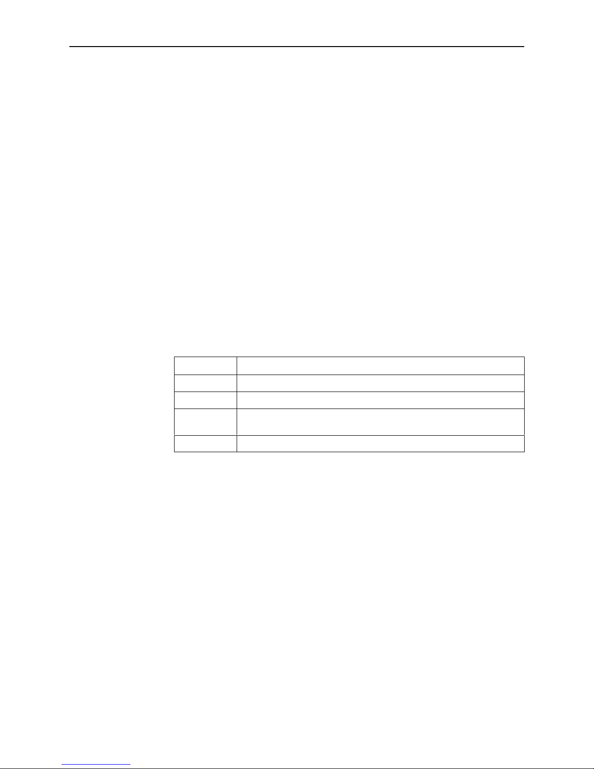
Table 1. AT Command String
Command
&C1 Configures your modem to raise LSD after establishing a connection.
&D2 Configures your modem to drop connection when the DSU drops DTR.
&S1 Configures your modem to raise DSR when it begins to establish a
S0=1 Configures your modem to automatically answer incoming calls.
Description
connection.
4
February 2000
7112-A2-GN10-40
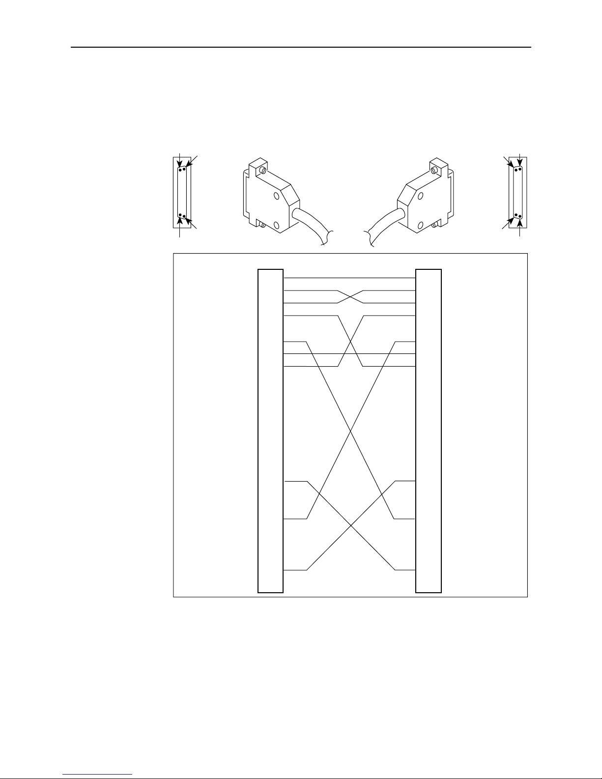
NOTE:
The Pin 17 to Pin 24 crossovers shown in Figure 1 are not required and have
no effect with the Model 7112.
Pin 14
Pin 1
Pin 13
Pin 25
Chassis Ground
Signal Ground
CD (RLSD)
P1
RXD
DSR
RXC
DTR
XTXC
TXD
RTS
CTS
TXC
Pin
1
2
3
4
5
6
7
8
9
10
11
12
13
14
15
16
17
18
19
20
21
22
23
24
25
P1
Plug
P2
Plug
Pin P2
1
2
3
4
5
6
7
8
9
10
11
12
13
14
15
16
17
18
19
20
21
22
23
24
25
Pin 14
Pin 25
Chassis Ground
TXD
RXD
RTS
CTS
DSR
Signal Ground
CD (RLSD)
TXC
RXC
DTR
XTXC
Pin 1
Pin 13
98-15811
Figure 1. Serial Crossover Cable for External Modem
7112-A2-GN10-40
February 2000
5
 Loading...