

Page 1

AREA CODE CHANGE
Please note that the area code for
Paradyne Corporation in Largo, Florida
has changed from 813 to 727.
For any Paradyne telephone number that
appears in this manual with an 813 area
code, dial 727 instead.
Page 2

COMSPHERE
6800 SERIES NETWORK
MANAGEMENT SYSTEM
INSTALLATION AND MAINTENANCE GUIDE
Document No. 6800-A2-GN22-30
January 1997
NOTE
This document supports Release 4.2 or greater of 6800 Series NMS.
Page 3

COMSPHERE 6800 Series Network Management System
COMSPHERE
6800 Series Network Management System
Installation and Maintenance Guide
6800-A2-GN22-30
4th Edition (January 1997)
Changes and enhancements to the product and to the information herein will be documented and issued as a new release
to this manual.
Warranty, Sales, and Service Information
Contact your sales or service representative directly for any help needed. For additional information concerning
warranty, sales, service, repair, installation, documentation, or training, use one of the following methods:
• Via the Internet: Visit the Paradyne World Wide Web site at http://www.paradyne.com
• Via Telephone: Call our automated call system to receive current information via fax or to speak with a company
representative.
— Within the U.S.A., call 1-800-870-2221
— International, call 813-530-2340
Trademarks
All products and services mentioned herein are the trademarks, service marks, registered trademarks or registered
service marks of their respective owners.
Printed on recycled paper
COPYRIGHT 1997 Paradyne Corporation. All rights reserved.
This publication is protected by federal copyright law. No part of this publication may be copied or distributed, transmitted, transcribed, stored in a retrieval system,
or translated into any human or computer language in any form or by any means, electronic, mechanical, magnetic, manual or otherwise, or disclosed to third parties
without the express written permission of Paradyne Corporation, 8545 126th Avenue North, P.O. Box 2826, Largo, Florida 33779-2826.
Paradyne Corporation makes no representation or warranties with respect to the contents hereof and specifically disclaims any implied warranties of merchantability
or fitness for a particular purpose. Further, Paradyne Corporation reserves the right to revise this publication and to make changes from time to time in the contents
hereof without obligation of Paradyne Corporation to notify any person of such revision or changes.
A January 1997 6800-A2-GN22-30
Page 4

Important Safety Instructions
1. Read and follow all warning notices and instructions marked on the product or
included in the manual.
2. This product is intended to be used with a three-wire grounding type plug - a plug
which has a grounding pin. This is a safety feature. Equipment grounding is vital to
ensure safe operation. Do not defeat the purpose of the grounding type plug by
modifying the plug or using an adaptor.
Prior to installation, use an outlet tester or a voltmeter to check the ac receptacle for
the presence of earth ground. If the receptacle is not properly grounded, the
installation must not continue until a qualified electrician has corrected the problem.
If a three-wire grounding type power source is not available, consult a qualified
electrician to determine another method of grounding the equipment.
3. Slots and openings in the cabinet are provided for ventilation. To ensure reliable
operation of the product and to protect it from overheating, these slots and openings
must not be blocked or covered.
4. Do not allow anything to rest on the power cord and do not locate the product where
persons will walk on the power cord.
Safety Instructions
5. Do not attempt to service this product yourself, as opening or removing covers may
expose you to dangerous high voltage points or other risks. Refer all servicing to
qualified service personnel.
6. General purpose cables are provided with this product. Special cables, which may be
required by the regulatory inspection authority for the installation site, are the
responsibility of the customer.
7. When installed in the final configuration, the product must comply with the applicable
Safety Standards and regulatory requirements of the country in which it is installed. If
necessary, consult with the appropriate regulatory agencies and inspection
authorities to ensure compliance.
8. A rare phenomenon can create a voltage potential between the earth grounds of two
or more buildings. If products installed in separate buildings are interconnected, the
voltage potential may cause a hazardous condition. Consult a qualified electrical
consultant to determine whether or not this phenomenon exists and, if necessary,
implement corrective action prior to interconnecting the products.
In addition, if the equipment is to be used with telecommunications circuits, take the
following precautions:
– Never install telephone wiring during a lightning storm.
– Never install telephone jacks in wet locations unless the jack is specifically designed
for wet locations.
– Never touch uninsulated telephone wires or terminals unless the telephone line has
been disconnected at the network interface.
– Use caution when installing or modifying telephone lines.
– Avoid using a telephone (other than a cordless type) during an electrical storm.
There may be a remote risk of electric shock from lightning.
– Do not use the telephone to report a gas leak in the vicinity of the leak.
B6800-A2-GN22–30 January 1997
Page 5

COMSPHERE 6800 Series Network Management System
Notices
! ! ! ! !
!
! !!
C January 1997 6800-A2-GN22-30
Page 6

Table of Contents
Preface
Objectives and Reader Assumptions xi. . . . . . . . . . . . . . . . . . . . . . . . . . .
Abstract xii. . . . . . . . . . . . . . . . . . . . . . . . . . . . . . . . . . . . . . . . . . . . . . . . .
Documentation Conventions xii. . . . . . . . . . . . . . . . . . . . . . . . . . . . . . . . .
Related Documents xii. . . . . . . . . . . . . . . . . . . . . . . . . . . . . . . . . . . . . . . .
1. Introduction
Overview 1-1. . . . . . . . . . . . . . . . . . . . . . . . . . . . . . . . . . . . . . . . . . . . . . . .
Selecting A Site 1-5. . . . . . . . . . . . . . . . . . . . . . . . . . . . . . . . . . . . . . . . . . .
Contents List 1-6. . . . . . . . . . . . . . . . . . . . . . . . . . . . . . . . . . . . . . . . . . . . .
2. Preparing the Processors
Overview 2-2. . . . . . . . . . . . . . . . . . . . . . . . . . . . . . . . . . . . . . . . . . . . . . . .
Altos System 5000 Host 2-3. . . . . . . . . . . . . . . . . . . . . . . . . . . . . . . . . . . . .
Optional Host Upgrade Packages 2-8. . . . . . . . . . . . . . . . . . . . . . . . . . . . .
Optional Host Upgrade Procedures 2-14. . . . . . . . . . . . . . . . . . . . . . . . . . . .
Altos System 5000 UIP 2-21. . . . . . . . . . . . . . . . . . . . . . . . . . . . . . . . . . . . .
Altos System 15000 2-30. . . . . . . . . . . . . . . . . . . . . . . . . . . . . . . . . . . . . . . .
EISA Configuration Utility 2-46. . . . . . . . . . . . . . . . . . . . . . . . . . . . . . . . . .
Full-Feature Workstation 2-51. . . . . . . . . . . . . . . . . . . . . . . . . . . . . . . . . . . .
3. Preparing the Printers
Overview 3-1. . . . . . . . . . . . . . . . . . . . . . . . . . . . . . . . . . . . . . . . . . . . . . . .
Fujitsu DL5600 3-2. . . . . . . . . . . . . . . . . . . . . . . . . . . . . . . . . . . . . . . . . . .
Fujitsu DL3400 3-5. . . . . . . . . . . . . . . . . . . . . . . . . . . . . . . . . . . . . . . . . . .
Fujitsu DL3600 3-8. . . . . . . . . . . . . . . . . . . . . . . . . . . . . . . . . . . . . . . . . . .
Fujitsu DX2300 3-12. . . . . . . . . . . . . . . . . . . . . . . . . . . . . . . . . . . . . . . . . . .
C.ITOH C-240 3-17. . . . . . . . . . . . . . . . . . . . . . . . . . . . . . . . . . . . . . . . . . . .
Network Printers 3-19. . . . . . . . . . . . . . . . . . . . . . . . . . . . . . . . . . . . . . . . . .
i6800-A2-GN22-30 January 1997
Page 7

COMSPHERE 6800 Series Network Management System
4. Connecting the Components
Overview 4-2. . . . . . . . . . . . . . . . . . . . . . . . . . . . . . . . . . . . . . . . . . . . . . . .
System Console 4-3. . . . . . . . . . . . . . . . . . . . . . . . . . . . . . . . . . . . . . . . . . .
Altos 5000 Full-Feature Workstation Configuration 4-4. . . . . . . . . . . . . . .
Altos 15000 Full-Feature Workstation Configuration 4-10. . . . . . . . . . . . . .
Basic-Feature W orkstation 4-14. . . . . . . . . . . . . . . . . . . . . . . . . . . . . . . . . . .
Printers 4-18. . . . . . . . . . . . . . . . . . . . . . . . . . . . . . . . . . . . . . . . . . . . . . . . . .
Data Communications Equipment 4-22. . . . . . . . . . . . . . . . . . . . . . . . . . . . .
External Systems 4-35. . . . . . . . . . . . . . . . . . . . . . . . . . . . . . . . . . . . . . . . . .
Netview/PC 4-43. . . . . . . . . . . . . . . . . . . . . . . . . . . . . . . . . . . . . . . . . . . . . .
Automatic Trouble Report Feature 4-45. . . . . . . . . . . . . . . . . . . . . . . . . . . .
Accumaster Integrator 4-46. . . . . . . . . . . . . . . . . . . . . . . . . . . . . . . . . . . . . .
Analysis Network Management System 4-50. . . . . . . . . . . . . . . . . . . . . . . .
StarKeeper Network Management System 4-54. . . . . . . . . . . . . . . . . . . . . .
Bytex UMS 4-56. . . . . . . . . . . . . . . . . . . . . . . . . . . . . . . . . . . . . . . . . . . . . .
5. Loading and Restoring Software
Overview 5-2. . . . . . . . . . . . . . . . . . . . . . . . . . . . . . . . . . . . . . . . . . . . . . . .
Network Preinstallation Preparation 5-4. . . . . . . . . . . . . . . . . . . . . . . . . . .
Inserting the Software Media 5-6. . . . . . . . . . . . . . . . . . . . . . . . . . . . . . . . .
UNIX Software for the Host Processor 5-6. . . . . . . . . . . . . . . . . . . . . . . . .
Installing the MPX Software on the Altos 15000 5-19. . . . . . . . . . . . . . . . .
Release 4.2 NMS Software 5-21. . . . . . . . . . . . . . . . . . . . . . . . . . . . . . . . . .
Unix Software for the UIP 5-41. . . . . . . . . . . . . . . . . . . . . . . . . . . . . . . . . . .
UIP Software 5-50. . . . . . . . . . . . . . . . . . . . . . . . . . . . . . . . . . . . . . . . . . . . .
Full-Feature Workstation Software 5-59. . . . . . . . . . . . . . . . . . . . . . . . . . . .
Basic-Feature W orkstation Software 5-86. . . . . . . . . . . . . . . . . . . . . . . . . . .
Installing the Analysis Gateway Option (5000 Systems Only) 5-90. . . . . . .
Setting Data Rates 5-100. . . . . . . . . . . . . . . . . . . . . . . . . . . . . . . . . . . . . . . . .
6. System Start-Up and Shutdown
Overview 6-1. . . . . . . . . . . . . . . . . . . . . . . . . . . . . . . . . . . . . . . . . . . . . . . .
Starting UNIX on the Host 6-2. . . . . . . . . . . . . . . . . . . . . . . . . . . . . . . . . .
Starting the NMS Application Program 6-2. . . . . . . . . . . . . . . . . . . . . . . . .
Shutting Down the NMS Application Program 6-5. . . . . . . . . . . . . . . . . . .
Shutting Down UNIX on the Host 6-7. . . . . . . . . . . . . . . . . . . . . . . . . . . . .
Starting UNIX on the UIP 6-8. . . . . . . . . . . . . . . . . . . . . . . . . . . . . . . . . . .
Starting the UIP Application Program 6-8. . . . . . . . . . . . . . . . . . . . . . . . . .
Shutting Down the UIP Application Program 6-9. . . . . . . . . . . . . . . . . . . .
Shutting Down UNIX on the UIP 6-10. . . . . . . . . . . . . . . . . . . . . . . . . . . . .
7. Performing Migration
Overview 7-1. . . . . . . . . . . . . . . . . . . . . . . . . . . . . . . . . . . . . . . . . . . . . . . .
Introduction To Migrating Databases 7-2. . . . . . . . . . . . . . . . . . . . . . . . . .
Release 1 Database Migration 7-3. . . . . . . . . . . . . . . . . . . . . . . . . . . . . . . .
Release 2 Database Migration 7-16. . . . . . . . . . . . . . . . . . . . . . . . . . . . . . . .
Release 3.0/3.1 Database Migration 7-25. . . . . . . . . . . . . . . . . . . . . . . . . . .
Release 4.0/4.1 Database Migration 7-33. . . . . . . . . . . . . . . . . . . . . . . . . . .
ii January 1997 6800-A2-GN22-30
Page 8

8. Running Diagnostics
Overview 8-1. . . . . . . . . . . . . . . . . . . . . . . . . . . . . . . . . . . . . . . . . . . . . . . .
SDX Diagnostic Program 8-2. . . . . . . . . . . . . . . . . . . . . . . . . . . . . . . . . . .
StarLAN 10 NAU Diagnostic Program 8-4. . . . . . . . . . . . . . . . . . . . . . . . .
IPC-900 Diagnostic Program (for Altos 5000 Systems Only) 8-5. . . . . . . .
IPC-1600 Diagnostic Program 8-9. . . . . . . . . . . . . . . . . . . . . . . . . . . . . . . .
Emulex DCP-286i Diagnostic Program
(for Altos 5000 Systems Only) 8-12. . . . . . . . . . . . . . . . . . . . . . . . . . . . . .
Emulex DCP/MUXi Diagnostic Program 8-13. . . . . . . . . . . . . . . . . . . . . . .
Appendices
A. Modem Settings A-1. . . . . . . . . . . . . . . . . . . . . . . . . . . . . . . . . . . . . . .
B. Adapter and Cable Identification B-1. . . . . . . . . . . . . . . . . . . . . . . . . .
C. Maintaining Multiplexers C-1. . . . . . . . . . . . . . . . . . . . . . . . . . . . . . . .
Table of Contents
iii6800-A2-GN22-30 January 1997
Page 9

List of Figures
Figure Page
1-1 6800 Series NMS Showing Configuration of all Ports and UIP 1-3. . . . . . . . . . . . . . . .
1-2 High Capacity 6800 Series NMS Showing Configuration of all Ports and
Two UIPs 1-4. . . . . . . . . . . . . . . . . . . . . . . . . . . . . . . . . . . . . . . . . . . . . . . . . . . . . . . . . .
2-1 System 5000 — Cover Fasteners 2-5. . . . . . . . . . . . . . . . . . . . . . . . . . . . . . . . . . . . . . . .
2-2 System 5000 — Disengaging Cover Locking Pins 2-6. . . . . . . . . . . . . . . . . . . . . . . . . .
2-3 Integral Ethernet Card 2-7. . . . . . . . . . . . . . . . . . . . . . . . . . . . . . . . . . . . . . . . . . . . . . . .
2-4 Second and Third Hard Disk Jumper Settings 2-9. . . . . . . . . . . . . . . . . . . . . . . . . . . . . .
2-5 IPC-900 — Switch and Jumper Locations 2-10. . . . . . . . . . . . . . . . . . . . . . . . . . . . . . . . .
2-6 Emulex DCP-286i — Switch and Jumper Locations 2-12. . . . . . . . . . . . . . . . . . . . . . . .
2-7 DCP/MUXi Card 2-13. . . . . . . . . . . . . . . . . . . . . . . . . . . . . . . . . . . . . . . . . . . . . . . . . . . .
2-8 Altos 5000 Disk Bay 2-15. . . . . . . . . . . . . . . . . . . . . . . . . . . . . . . . . . . . . . . . . . . . . . . . .
2-9 System 5000 — Expansion Slots 2-16. . . . . . . . . . . . . . . . . . . . . . . . . . . . . . . . . . . . . . . .
2-10 Emulex DCP/MUCi — Circuit Card and Cable Assembly 2-17. . . . . . . . . . . . . . . . . . . .
2-11 16-Port Cabinet Assembly 2-19. . . . . . . . . . . . . . . . . . . . . . . . . . . . . . . . . . . . . . . . . . . . .
2-12 80-Pin Headers P3 and P4 Connector Identification 2-20. . . . . . . . . . . . . . . . . . . . . . . . .
2-13 IPC-1600 Ports Cabinet Assembly 2-21. . . . . . . . . . . . . . . . . . . . . . . . . . . . . . . . . . . . . .
2-14 IPC-1600 — Switch and Jumper Locations and Settings 2-26. . . . . . . . . . . . . . . . . . . . .
2-15 System 15000 — Removing the Top Cover 2-32. . . . . . . . . . . . . . . . . . . . . . . . . . . . . . .
2-16 System 15000 — Removing the Side Panel 2-33. . . . . . . . . . . . . . . . . . . . . . . . . . . . . . .
2-17 System 15000 — Removing the Front Panel 2-34. . . . . . . . . . . . . . . . . . . . . . . . . . . . . . .
2-18 Altos 15000 Main Processor Card and MPX 2-35. . . . . . . . . . . . . . . . . . . . . . . . . . . . . . .
2-19 Altos 15000 Motherboard and Bus Connectors 2-36. . . . . . . . . . . . . . . . . . . . . . . . . . . . .
2-20 Altos 15000 Showing the Hard Disk Bay 2-38. . . . . . . . . . . . . . . . . . . . . . . . . . . . . . . . .
2-21 Altos 15000 Memory Board and Memory Modules 2-39. . . . . . . . . . . . . . . . . . . . . . . . .
2-22 System 15000 — Expansion Slots 2-42. . . . . . . . . . . . . . . . . . . . . . . . . . . . . . . . . . . . . . .
2-23 System 15000 — Top Cover Locking Pins 2-44. . . . . . . . . . . . . . . . . . . . . . . . . . . . . . . .
2-24 Boot Menu 2-47. . . . . . . . . . . . . . . . . . . . . . . . . . . . . . . . . . . . . . . . . . . . . . . . . . . . . . . . .
2-25 Main Menu 2-48. . . . . . . . . . . . . . . . . . . . . . . . . . . . . . . . . . . . . . . . . . . . . . . . . . . . . . . . .
2-26 Configure Computer Menu 2-48. . . . . . . . . . . . . . . . . . . . . . . . . . . . . . . . . . . . . . . . . . . .
2-27 EtherLink II Card Jumper Settings 2-51. . . . . . . . . . . . . . . . . . . . . . . . . . . . . . . . . . . . . .
2-28 Proteon p1392 Card 2-53. . . . . . . . . . . . . . . . . . . . . . . . . . . . . . . . . . . . . . . . . . . . . . . . . .
2-29 NAU Memory Jumper Locations and Settings 2-55. . . . . . . . . . . . . . . . . . . . . . . . . . . . .
3-1 DL5600 — Front Control Panel 3-2. . . . . . . . . . . . . . . . . . . . . . . . . . . . . . . . . . . . . . . .
3-2 DL3400 — Front Control Panel 3-5. . . . . . . . . . . . . . . . . . . . . . . . . . . . . . . . . . . . . . . .
3-3 DL3400 — SETUP Mode Opening Menu 3-6. . . . . . . . . . . . . . . . . . . . . . . . . . . . . . . . .
3-4 DL3600 — Front Control Panel 3-9. . . . . . . . . . . . . . . . . . . . . . . . . . . . . . . . . . . . . . . .
3-5 DL3600 — SETUP Mode Opening Menu 3-10. . . . . . . . . . . . . . . . . . . . . . . . . . . . . . . . .
3-6 DX2300 — Memory and Serial Interface Card Access 3-12. . . . . . . . . . . . . . . . . . . . . . .
3-7 DX2300 — Memory Card Settings 3-13. . . . . . . . . . . . . . . . . . . . . . . . . . . . . . . . . . . . . .
3-8 DX2300 — Serial Interface Card Settings (9600 Baud) 3-15. . . . . . . . . . . . . . . . . . . . . .
v6800-A2-GN22-30 January 1997
Page 10

COMSPHERE 6800 Series Network Management System
Figure Page
4-1 Altos System 5000 — Display Unit, Keyboard, and Mouse Ports 4-3. . . . . . . . . . . . . .
4-2 Altos System 15000 — Display Unit, Keyboard, and Mouse Ports 4-4. . . . . . . . . . . . .
4-3 Local Area Network with Second Full-Feature Workstation 4-6. . . . . . . . . . . . . . . . . .
4-4 Network Hub Unit 4-7. . . . . . . . . . . . . . . . . . . . . . . . . . . . . . . . . . . . . . . . . . . . . . . . . . .
4-5 Local Area Network with UIP 4-8. . . . . . . . . . . . . . . . . . . . . . . . . . . . . . . . . . . . . . . . . .
4-6 Local Area Network with Additional Full-Feature Workstations 4-9. . . . . . . . . . . . . . .
4-7 Altos 15000 Basic Local Area Network Configuration 4-10. . . . . . . . . . . . . . . . . . . . . . .
4-8 Altos 15000 Configuration for Additional Full-Feature Workstations 4-12. . . . . . . . . . .
4-9 Altos 15000 Cascaded Network Hub Units 4-13. . . . . . . . . . . . . . . . . . . . . . . . . . . . . . . .
4-10 Basic-Feature Workstation Configurations 4-15. . . . . . . . . . . . . . . . . . . . . . . . . . . . . . . .
4-11 Basic-Feature Workstation Configurations 4-16. . . . . . . . . . . . . . . . . . . . . . . . . . . . . . . .
4-12 Printer Connections 4-19. . . . . . . . . . . . . . . . . . . . . . . . . . . . . . . . . . . . . . . . . . . . . . . . . .
4-13 Daisy Chain 4-23. . . . . . . . . . . . . . . . . . . . . . . . . . . . . . . . . . . . . . . . . . . . . . . . . . . . . . . .
4-14 Local Control Channel Connections 4-24. . . . . . . . . . . . . . . . . . . . . . . . . . . . . . . . . . . . .
4-15 Remote Control Channel Connections 4-26. . . . . . . . . . . . . . . . . . . . . . . . . . . . . . . . . . . .
4-16 Connections for 719 NETWORKER to Host Processor 4-29. . . . . . . . . . . . . . . . . . . . . .
4-17 Connections for Two Local ACCULINK Multiplexers 4-30. . . . . . . . . . . . . . . . . . . . . . .
4-18 Connections for One Local ACCULINK Multiplexer and
One 719 NETWORKER 4-31. . . . . . . . . . . . . . . . . . . . . . . . . . . . . . . . . . . . . . . . . . . . . .
4-19 Connections for One Local ACCULINK Multiplexer 4-32. . . . . . . . . . . . . . . . . . . . . . . .
4-20 External Systems Connections 4-36. . . . . . . . . . . . . . . . . . . . . . . . . . . . . . . . . . . . . . . . . .
4-21 Netview/PC Connection 4-43. . . . . . . . . . . . . . . . . . . . . . . . . . . . . . . . . . . . . . . . . . . . . . .
4-22 A TR Connection 4-45. . . . . . . . . . . . . . . . . . . . . . . . . . . . . . . . . . . . . . . . . . . . . . . . . . . . .
4-23 ACCUMASTER Integrator Local Connection via UAI and File Export 4-46. . . . . . . . .
4-24 ACCUMASTER Integrator Remote Connection 4-48. . . . . . . . . . . . . . . . . . . . . . . . . . . .
4-25 ANAL YSIS 6510/5605 AND 5600 Local Connection 4-51. . . . . . . . . . . . . . . . . . . . . . .
4-26 ANAL YSIS 6510/5605 and 5600 Remote Connection 4-52. . . . . . . . . . . . . . . . . . . . . . .
4-27 StarKeeper Connection 4-54. . . . . . . . . . . . . . . . . . . . . . . . . . . . . . . . . . . . . . . . . . . . . . .
4-28 Bytex UMS Connection 4-56. . . . . . . . . . . . . . . . . . . . . . . . . . . . . . . . . . . . . . . . . . . . . . .
5-1 Cartridge T ape Drive 5-6. . . . . . . . . . . . . . . . . . . . . . . . . . . . . . . . . . . . . . . . . . . . . . . . .
5-2 System 5000 Boot Menu (Installing UNIX on Host Computer) 5-7. . . . . . . . . . . . . . . .
5-3 Installation Procedure Menu (Installing UNIX on Host Computer) 5-8. . . . . . . . . . . . .
5-4 Hardware Configuration Menu (Installing UNIX on Host Computer) 5-9. . . . . . . . . . .
5-5 AT&T Paradyne NMS Parameters Menu 5-29. . . . . . . . . . . . . . . . . . . . . . . . . . . . . . . . .
5-6 System 5000 Boot Menu (Installing UNIX on UIP) 5-41. . . . . . . . . . . . . . . . . . . . . . . . .
5-7 Installation Procedure Menu (Installing UNIX on UIP) 5-42. . . . . . . . . . . . . . . . . . . . . .
5-8 Hardware Configuration Menu (Installing UNIX on UIP) 5-43. . . . . . . . . . . . . . . . . . . .
5-9 ANALYSIS Selection Menu 5-94. . . . . . . . . . . . . . . . . . . . . . . . . . . . . . . . . . . . . . . . . . .
5-10 ANALYSIS Selection Menu (for Changing 6510 Parameters) 5-97. . . . . . . . . . . . . . . . .
6-1 Network Management System Menu 6-2. . . . . . . . . . . . . . . . . . . . . . . . . . . . . . . . . . . . .
6-2 FFW Login Window 6-4. . . . . . . . . . . . . . . . . . . . . . . . . . . . . . . . . . . . . . . . . . . . . . . . .
6-3 6800 Series NMS T asks Menu Window 6-4. . . . . . . . . . . . . . . . . . . . . . . . . . . . . . . . . .
6-4 Manager Window 6-5. . . . . . . . . . . . . . . . . . . . . . . . . . . . . . . . . . . . . . . . . . . . . . . . . . . .
6-5 Network Management System Menu 6-8. . . . . . . . . . . . . . . . . . . . . . . . . . . . . . . . . . . . .
7-1 AT&T Paradyne NMS Parameters Menu (Release 1 Database Migration) 7-9. . . . . . . .
7-2 Original Menu Showing Selected T ype (r1) 7-10. . . . . . . . . . . . . . . . . . . . . . . . . . . . . . .
7-3 AT&T Paradyne NMS Parameters Menu (Release 2 Database Migration) 7-19. . . . . . . .
7-4 Original Menu Showing Selected T ype (r2) 7-21. . . . . . . . . . . . . . . . . . . . . . . . . . . . . . .
7-5 AT&T Paradyne NMS Parameters Menu (Release 3.0/3.1 Database Migration) 7-27. . .
7-6 Original Menu Showing Selected T ype (r3) 7-29. . . . . . . . . . . . . . . . . . . . . . . . . . . . . . .
7-7 AT&T Paradyne NMS Parameters Menu (Release 4.0 Database Migration) 7-35. . . . . .
7-8 Original Menu Showing Selected T ype (R4) 7-37. . . . . . . . . . . . . . . . . . . . . . . . . . . . . . .
vi January 1997 6800-A2-GN22-30
Page 11

Table of Contents
Figure Page
8-1 Boot Menu 8-2. . . . . . . . . . . . . . . . . . . . . . . . . . . . . . . . . . . . . . . . . . . . . . . . . . . . . . . . .
8-2 SDX Main Menu 8-3. . . . . . . . . . . . . . . . . . . . . . . . . . . . . . . . . . . . . . . . . . . . . . . . . . . .
8-3 StarLAN IRQ Strapping 8-4. . . . . . . . . . . . . . . . . . . . . . . . . . . . . . . . . . . . . . . . . . . . . .
8-4 Port-to-Port Connections 8-8. . . . . . . . . . . . . . . . . . . . . . . . . . . . . . . . . . . . . . . . . . . . . .
8-5 Dip Switch Settings for Memory Address 8-9. . . . . . . . . . . . . . . . . . . . . . . . . . . . . . . . .
C-1 Power Connections for 740 Multiplexers without Expansion Shelf C-3. . . . . . . . . . . . .
C-2 Power Connections for 740 Multiplexers with Expansion Shelf C-4. . . . . . . . . . . . . . . .
C-3 Power Connections for 745 Multiplexers C-5. . . . . . . . . . . . . . . . . . . . . . . . . . . . . . . . .
C-4 4336 Power Supply for 740 Multiplexers C-6. . . . . . . . . . . . . . . . . . . . . . . . . . . . . . . . .
C-5 4336 Power Supply Connection for 745 Multiplexers C-7. . . . . . . . . . . . . . . . . . . . . . .
vii6800-A2-GN22-30 January 1997
Page 12

Table of Contents
List of Tables
Table Page
1-1 Processor Configurations 1-2. . . . . . . . . . . . . . . . . . . . . . . . . . . . . . . . . . . . . . . . . . . . . .
2-1 Altos 5000 Factory- and Field-Installable Circuit Cards 2-4. . . . . . . . . . . . . . . . . . . . . .
2-2 DCP/MUXi — I/O Address Switch Settings 2-13. . . . . . . . . . . . . . . . . . . . . . . . . . . . . . .
2-3 Altos 5000 UIP Factory- and Field-Installable Circuit Cards 2-22. . . . . . . . . . . . . . . . . .
2-4 Altos 5000 UIP Conversion Matrix 2-27. . . . . . . . . . . . . . . . . . . . . . . . . . . . . . . . . . . . . .
2-5 Altos 15000 Factory- and Field-Installable Circuit Cards 2-30. . . . . . . . . . . . . . . . . . . . .
2-6 IPC-1600 — Memory Switch Settings (DSI) 2-40. . . . . . . . . . . . . . . . . . . . . . . . . . . . . .
2-7 DCP-MUXI — I/O Address Switch Settings 2-41. . . . . . . . . . . . . . . . . . . . . . . . . . . . . .
2-8 Configuration Files 2-46. . . . . . . . . . . . . . . . . . . . . . . . . . . . . . . . . . . . . . . . . . . . . . . . . .
2-9 Token Ring I/O Address Switch Setting 2-52. . . . . . . . . . . . . . . . . . . . . . . . . . . . . . . . . .
2-10 6386/25 Circuit Cards to Be Removed 2-54. . . . . . . . . . . . . . . . . . . . . . . . . . . . . . . . . . .
3-1 DL3600 — MENU1 Settings 3-10. . . . . . . . . . . . . . . . . . . . . . . . . . . . . . . . . . . . . . . . . . .
3-2 DL3600 — HARDWARE Settings 3-11. . . . . . . . . . . . . . . . . . . . . . . . . . . . . . . . . . . . . .
3-3 Memory Card DIP Switch Settings 3-14. . . . . . . . . . . . . . . . . . . . . . . . . . . . . . . . . . . . . .
3-4 Serial Interface Card Settings Switches 1—5 3-16. . . . . . . . . . . . . . . . . . . . . . . . . . . . . .
3-5 Serial Interface Card Settings Switches 6—8 3-16. . . . . . . . . . . . . . . . . . . . . . . . . . . . . .
3-6 C.ITOH C-240 Setting Changes 3-17. . . . . . . . . . . . . . . . . . . . . . . . . . . . . . . . . . . . . . . .
3-7 Printer Functions Printout 3-18. . . . . . . . . . . . . . . . . . . . . . . . . . . . . . . . . . . . . . . . . . . . .
4-1 Cascaded Hub Cable Modifications 4-14. . . . . . . . . . . . . . . . . . . . . . . . . . . . . . . . . . . . . .
4-2 NMS Printer Models 4-18. . . . . . . . . . . . . . . . . . . . . . . . . . . . . . . . . . . . . . . . . . . . . . . . .
5-1 Altos 5000 Basic Network Configuration Parameters 5-4. . . . . . . . . . . . . . . . . . . . . . . .
5-2 Altos 15000 Basic Network Configuration Parameters 5-5. . . . . . . . . . . . . . . . . . . . . . .
5-3 NMS Parameters Menu — Options 5-29. . . . . . . . . . . . . . . . . . . . . . . . . . . . . . . . . . . . . .
6-1 Host Processor Start-Up, Reset, and Shutdown Modifications 6-1. . . . . . . . . . . . . . . . .
6-2 UIP Start-Up and Shutdown 6-1. . . . . . . . . . . . . . . . . . . . . . . . . . . . . . . . . . . . . . . . . . .
A-1 Modem Hardware and Configuration Option Switch Settings A-2. . . . . . . . . . . . . . . . .
B-1 Adapter and Cable Identification B-1. . . . . . . . . . . . . . . . . . . . . . . . . . . . . . . . . . . . . . . .
C-1 NMS Commands C-10. . . . . . . . . . . . . . . . . . . . . . . . . . . . . . . . . . . . . . . . . . . . . . . . . . . .
ix6800-A2-GN22-30 January 1997
Page 13

Preface
Objectives And Reader Assumptions
The COMSPHERE 6800 Series Network Management System Installation and Maintenance Guide
provides detailed instructions for installing and maintaining new network management systems,
and for migrating from existing Release 1, 2, 3.x, or 4.1 6800 Series NMS systems to the Release
4.2 6800 Series NMS. This guide was written to assist technical personnel at customer sites and
Paradyne service technicians.
Abstract
This guide is organized into the following chapters and appendices:
Chapter 1. Introduction. This chapter provides an overview of the COMSPHEREr 6800 Series
NMS hardware and software components, describes site selection, and provides a contents list of
the hardware and software supported by the 6800 Series NMS.
Chapter 2. Preparing the Processors. This chapter identifies the Altos System 5000 and System
15000 internal circuit cards and slots, their field upgrade packages, and procedures for installation.
It also provides information and procedures for running configuration utility programs.
Chapter 3. Preparing the Printers. This chapter provides information for configuring and
connecting printers supported by the NMS.
Chapter 4. Connecting the Components. This chapter provides information and procedures for
connecting the external NMS components to the host and, if present, to the User Interface
Processor (UIP).
Chapter 5. Loading and Restoring Software. This chapter provides procedural information for
installing the required software for the host processor, User Interface Processor (UIP), full-feature
workstations, and basic-feature workstations.
Chapter 6. System Start-up and Shutdown. This chapter provides procedural information for
starting and shutting down UNIXr on the host, the NMS applications program, the User Interface
Processor (UIP) application program, and UNIX on the User Interface Processor (UIP).
Chapter 7. Performing Migration. This chapter provides procedural information for migrating
previous NMS release databases to Release 4.2 of the 6800 Series NMS.
xi6800-A2-GN22-30 January 1997
Page 14

COMSPHERE 6800 Series Network Management Systems
Chapter 8. Running Diagnostics. This chapter provides information on how to use the diagnostic
programs that are shipped with the NMS. These diagnostic programs are used to detect and solve
hardware problems in the Altos System 5000, the Altos System 15000, and in the circuit cards
installed in these systems.
Appendix A. Modem Settings. This appendix describes the settings for hardware and software
configuration of modems connecting remote NMS devices.
Appendix B. Adapter and Cable Identification. This appendix provides information for each
adapter/cable descriptions, usage descriptions and pin information for each cable and adapter
described in this guide.
Appendix C. Maintaining Multiplexers. This appendix provides information on general
troubleshooting procedures, command port failure recovery, event port failure recovery, and
external systems port failure recovery.
Documentation Conventions
The following convention has been used throughout this document.
Typeface
This typeface indicates messages that appear on the screen.
Related Documents
Contact your sales representative to order additional product documentation.
The following documents contain information pertinent to the installation process.
305-910 AT&T Intelligent Ports Card Model 900 (IPC-900) User’s Guide
305-920 AT&T Intelligent Ports Card Model 1600 (IPC-1600) User’s Guide
999-100-292 AT&T 2224-CEO Modem User’s Guide
999-100-432 StarLAN 10 Network PC NAU Installation Guide
6500-A2-GA21 ANALYSIS 6510 Automated Network Management System Reference
6510-A2-GN31 Network Management Workstation User’s Guide
6800-A2-GB20 COMSPHERE 6800 Series Network Management System
Manual
Communications Products Support Configuration Guide
6800-A2-GB21 COMSPHERE 6800 Series Network Management System Multiplexer
Management and Configuration Guide
6800-A2-GB30 COMSPHERE 6800 Series Network Management System Core
Command Reference Manual
xii January 1997 6800-A2-GN22-30
Page 15

Preface
6800-A2-GB31 COMSPHERE 6800 Series Network Management System
Communications Products Support Command Reference Manual
6800-A2-GB33 COMSPHERE 6800 Series Network Management System 3270 Terminal
Emulation Option Supplement
6800-A2-GE26 COMSPHERE 6800 Series Network Management System User’s/
System Administrator’ s Guide
690-23502-002 Altos System 5000 Owner’s Guide
690-25428-002 Altos System 10000/15000 Owner’s Guide
B-69292 F/I Rev. D Fujitsu DX2300/2400 Printers User’s Manual (Type F)
B-69337 Rev. A Fujitsu DL5600 Dot Matrix Printer User’s Manual
B-69431 Rev. C Fujitsu DL3300/3400 Printers User’s Manual
PT1050954-00 Rev. C DCP/MUXi Installation Guide
PT1050956-00 Rev. A DCP 286-i Installation Guide
E1-300 34H C-240/245 User’s Manual
62FH 5009E-02 Fujitsu DL3600 User’s and Programmer’s Manual
42-040295-00 Rev. C ProNet – 4/16 Network Interface Cards User Guide
xiii6800-A2-GN22-30 January 1997
Page 16

Overview
Introduction
Overview 1-1. . . . . . . . . . . . . . . . . . . . . . . . . . . . . . . . . . . . . . . . . . . . . . . . . . . .
Selecting a Site 1-5. . . . . . . . . . . . . . . . . . . . . . . . . . . . . . . . . . . . . . . . . . . . . . . .
Contents List 1-6. . . . . . . . . . . . . . . . . . . . . . . . . . . . . . . . . . . . . . . . . . . . . . . . . .
The COMSPHEREr 6800 Series Network Management System (NMS) manages Analog Private
Line (APL) modems, switched network modems, Data Service Units (DSUs), and ACCULINK
multiplexers.
The Release 4.2 NMS provides two areas of improvement over previous releases: increased
database and workstation capacity and a new feature set. The current software release is
available on two hardware platforms: the Altos System 5000 and the Altos System 15000. The
fundamental difference between the two platforms is that both the capacity enhancements and
the new feature set are available on the Altos 15000 platform and only the new features are
available on the Altos 5000 platform.
The Altos 5000 platform is nearly identical to the hardware configuration seen in Release 3.1
and Release 4.1. Basic optional differences are the Token Ring Local Area Network (LAN)
support, third hard disk drive support for automatic database backup and restore, and support for
16 control channels with a second DCP-MUXi card.
1
The Altos 15000 platform consists of a multiprocessor and two mandatory User Interface
Processors (UIPs). This hardware configuration allows a larger number of simultaneous users,
workstations, and devices than previous releases. The configuration also supports the new feature
set.
Table 1-1 shows the configurations for the five processors. The differences among the processors
include the type of LAN which they use to communicate among host, UIP, and full-feature
workstations, and the availability of the optional feature packages. Communication with the
basic-feature workstations is done through the serial ports on the processors.
1-16800-A2-GN22-30 January 1997
Page 17

COMSPHERE 6800 Series Network Management System
Processor Configurations
Table 1-1
Altos 15000 Host
Altos 5000 Host
with Ethernet
Altos 5000 UIP
with Ethernet
Altos 5000 Host
with Token Rink
Altos 5000 UIP
with Token Ring
2 UIP 1 UIP (optional) — 1 UIP (optional) —
Ethernet Network Ethernet Network Ethernet Network Token Ring Network Token Ring Network
16 Control Channel
package
— ANALYSIS NMS
— 3270 Emulation
— — Serial Port Upgrade
SNMP Trap Export
package (optional)
Database
Customization
packages (optional)
Workstations:
24 full-feature
18 basic-feature
16 Control Channel
package (optional)
Package (optional)
package (optional)
SNMP Trap Export
package (optional)
Database
Customization
packages (optional)
Workstations:
with UIP —
6 full-feature
1 1 basic-feature
without UIP —
2 full-feature
3 basic-feature
1
1
1
package (optional)
— 16 Control Channel
package (optional)
— ANALYSIS NMS
package (optional)
— 3270 Emulation
package (optional)
2
— Serial Port Upgrade
— SNMP Trap Export
package (optional)
— Database
Customization
packages (optional)
— Workstations:
with UIP —
6 full-feature
1 1 basic-feature
without UIP —
2 full-feature
3 basic-feature
1
1
1
package (optional)
—
—
—
—
—
—
AutoBackup package AutoBackup package
(optional)
— AutoBackup package
(optional)
—
NOTES: Packages and features not marked as optional are required.
Altos 5000 UIP is used with both the Altos 5000 and Altos 15000 host. It is optional with the 5000. Two UIPs are
required with the 15000
Workstation configurations are the maximum number allowed. The NMS requires a minimum of one full-feature
workstation attached to the host.
1
The 16 Control Channel package cannot be installed on the Altos System 5000 in conjunction with either or both of the
ANALYSIS or 3270 Emulation packages.
2
The Serial Port Upgrade package must be installed on UIP #1 to support 18 basic-feature workstations when the host is
an Altos System 15000.
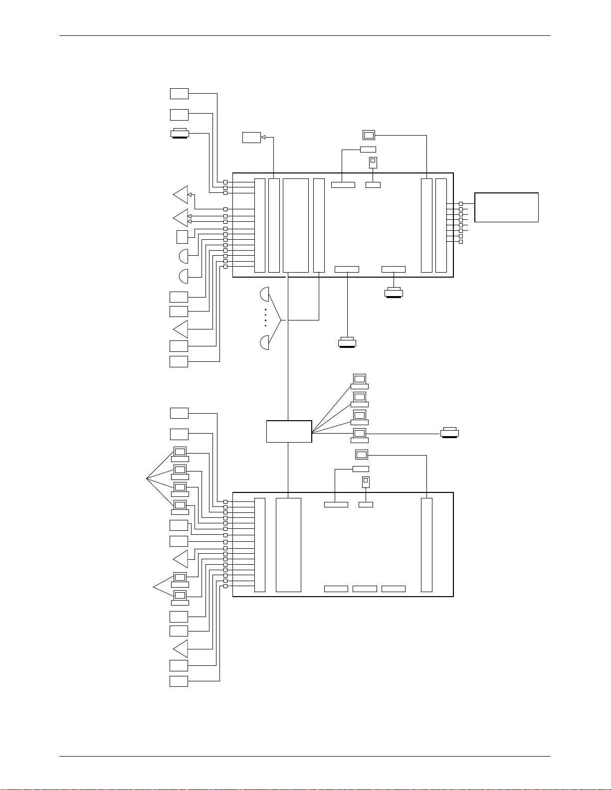
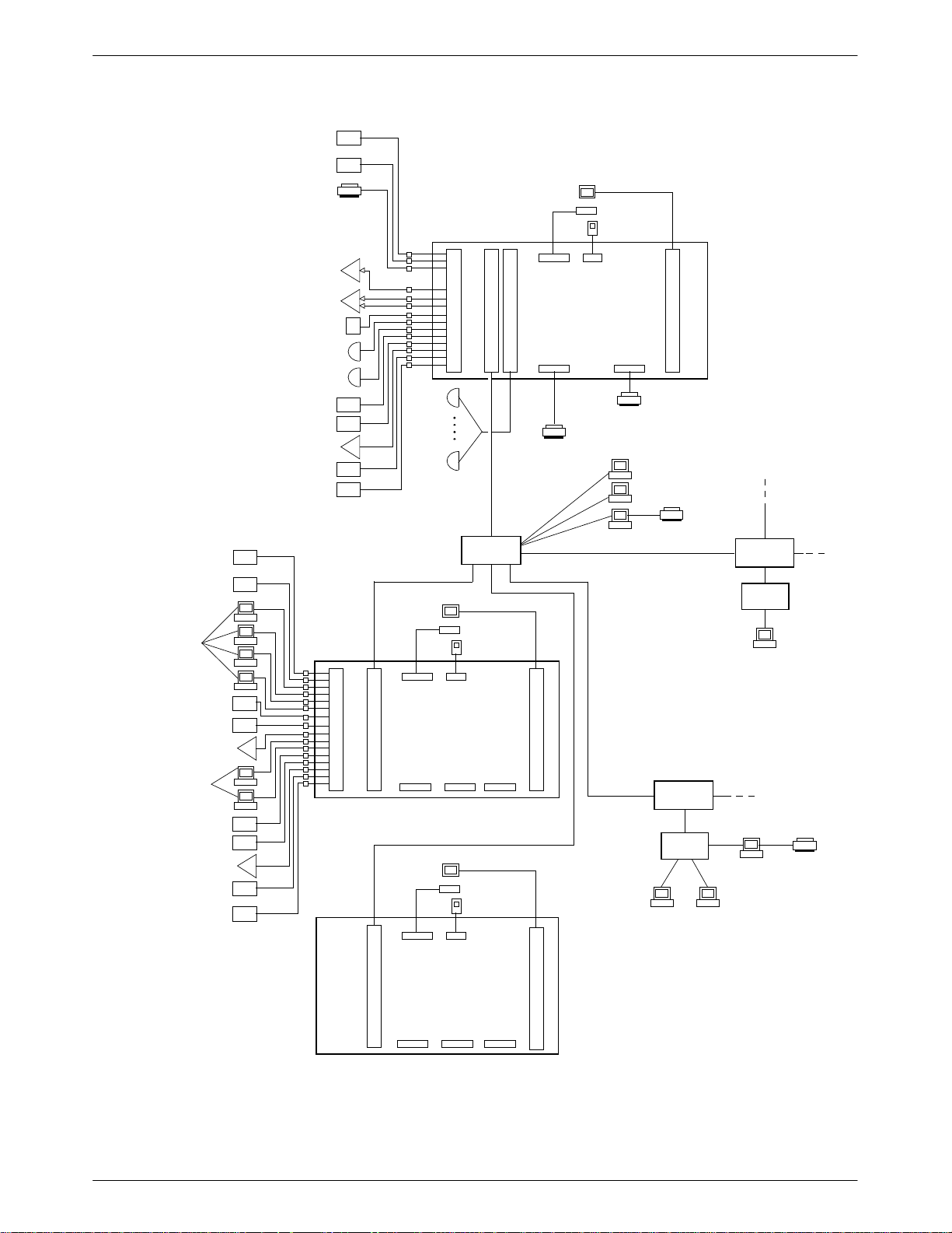
Figure 1-1 shows a host processor and UIP for the System 5000. Figure 1-2 shows a System
15000 host with two System 5000 UIPs.
1-2 January 1997 6800-A2-GN22-30
Page 18
Service Restoration
Control Unit
VT100 Emulation
(AT&T Mail)
Alert Log Printer
(or NetView PC)
SNA Host
Introduction
Monitor
Keyboard
Mouse
ACCULINK
Multiplexer
ACCULINK Multiplexer
Command and Event Interface
Automatic Trouble
Report Interface
UAI/AMI Alarms
AMI File Export
(UUCP)
839A Dial Backup
System Controller
DCX Multiplexer
Service Restoration
Control Unit
VT100 Emulation
Service Restoration
Control Unit
VT100 Emulation
(AT&T Mail)
Basic-Feature
Workstations
Modem
Control
Channels
1 – 8
Second
Card
Channels
9 – 16
(optional)
E
M
U
T
L
I
E
E
P
T
X
C
H
E
D
R
1
C
N
6
P
E
0
-
T
0
2
8
6
D
O
C
K
P
E
N
–
or
R
M
I
U
N
X
G
i
ALTOS
SYSTEM
5000
(Host)
PARALLEL SERIAL
I
P
S
C
V
G
9
A
0
0
ANALYSIS NMS
Alert Transport,
Printer Requests,
Cut-through Port
**
System
Printer
System Printer
Full-Feature
Workstations
NETWORK
HUB UNIT
Print Server
Monitor
Keyboard
Mouse
Network
Printer
839A Dial Backup
System Controller
DCX Multiplexer
Basic-Feature
Workstations
839A Dial Backup
System Controller
DCX Multiplexer
Service Restoration
Control Unit
VT100 Emulation
Figure 1-1. 6800 Series NMS Showing Configuration of all Ports and UIP
T
I
P
C
1
6
0
0
O
E
K
T
E
H
N
E
or
R
N
R
E
I
T
N
G
PARALLEL SERIAL SERIAL
ALTOS
SYSTEM
5000
(UIP)
S
V
G
A
* Compatible with a single DCP/MUXi only (8 control channels)
494-13051b-04
1-36800-A2-GN22-30 January 1997
Page 19
COMSPHERE 6800 Series Network Management System
Service Restoration Control Unit
VT100 Emulation (AT&T Mail)
Alert Log Printer (or NetView PC)
Monitor
Keyboard
Mouse
ACCULINK Multiplexer
ACCULINK Multiplexer
Command and Event Interface
Automatic Trouble Report Interface
UAI/AMI Alarms
AMI File Export (UUCP)
839A Dial Backup
System Controller
DCX Multiplexer
Service Restoration Control Unit
VT100 Emulation
Service Restoration
Control Unit
VT100 Emulation
(AT&T Mail)
Basic-Feature
Workstations
839A Dial Backup
System Controller
DCX Multiplexer
Basic-Feature
Workstations
I
P
C
1
6
0
0
D
E
C
T
P
H
E
–
R
N
M
E
U
T
X
i
PARALLEL SERIAL
ALTOS
SYSTEM
15000
(Host)
S
V
G
A
System Printer
System Printer
Modem
Control
Channels
1 – 16
NETWORK
HUB UNIT
Print Server
Full-Feature
Workstations
Network
Printer
ROUTER
– Maximum of
24 Full-Feature
Monitor
Keyboard
Mouse
I
E
P
T
C
H
E
1
R
6
N
0
E
0
T
PARALLEL SERIAL SERIAL
ALTOS
SYSTEM
5000
(UIP)
S
V
G
A
Workstations
– Maximum of
15 Network
Printers
– Maximum of
18 Basic-Feature
Workstations
ROUTER
HUB
Full-Feature
Workstation
839A Dial Backup
System Controller
DCX Multiplexer
Service Restoration
Control Unit
VT100 Emulation
Monitor
Keyboard
Mouse
HUB
Full-Feature
Print
Server
Network
Printer
Workstations
E
T
H
E
R
N
E
T
ALTOS
SYSTEM
5000
(UIP)
PARALLEL SERIAL SERIAL
S
V
G
A
494-14444-02
Figure 1-2. High Capacity 6800 Series NMS Showing Configuration of all Ports and Two UIPs
1-4 January 1997 6800-A2-GN22-30
Page 20

Selecting A Site
Select a site that provides easy access for cabling to the network and also provides adequate
work area for the system operators. The site should meet the following environmental
conditions:
• Temperature:
• Humidity:
• Power:
Introduction
+40°F to +90°F (+5°C to +32°C)
20% to 80% (noncondensing)
Input voltage range is determined by a voltage selection switch on the rear panel of the
chassis. The switch can be set manually to either 115 Vac or 230 Vac.
Power output: 395 watts for System 5000
Power output: 420—500 watts for System 15000
Power supply fuse type (internal only) rating: 10A/250V
• Physical Specifications:
— Altos System 5000
Height: 26.5 inches (67.3 cm)
Width: 8 inches (20.3 cm)
Depth: 19 inches (48.3 cm)
Weight: 75 lbs.
— Altos System 15000
Height: 26.5 inches (67.3 cm)
Width: 16 inches (40.6 cm)
Depth: 19 inches (48.3 cm)
Weight: 90 lbs.
1-56800-A2-GN22-30 January 1997
Page 21

COMSPHERE 6800 Series Network Management System
Contents List
The following hardware and software are supported by the 6800 Series NMS.
Host (Altos System 15000)
Four 16 Mb ECC memory modules
Three 520 Mb SCSI-II hard disk drives
150 Mb SCSI cartridge tape drive
3.5 inch floppy drive
VGA controller card
Ethernet Interface
IPC-1600 ports card
Two DCP/MUXi cards
PS/2 mouse
AT keyboard
Host (Altos System 5000/33)
Eight 4 Mb SIMMs
Two 520 Mb SCSI hard disk drives
150 Mb SCSI cartridge tape drive
3.5 inch floppy disk drive
VGA controller card
Ethernet Interface
IPC-1600 ports card
DCP/MUXi card
PS/2 mouse
AT keyboard
1-6 January 1997 6800-A2-GN22-30
Page 22

User Interface Processor
Altos System 5000/33 Processor
Eight 4 Mb SIMMs for UIP with System 5000 host
Twelve 4 Mb SIMMs for UIP with System 15000 host
One 520 Mb SCSI hard disk drive
150 Mb SCSI cartridge tape drive
3.5 inch floppy disk drive
VGA controller card
Ethernet Interface
PS/2 mouse
AT keyboard
Optional Components
Introduction
AT&T IPC-900 (required for ANALYSIS NMS support on Altos 5000 host only)
AT&T IPC-1600 (required for serial interface support on the Altos 5000 UIP only)
Emulex DCP-286i (required for 3270 T erminal Emulation support on Altos 5000 host
only)
Proteonr Token Ring EISA Network Interface Card (for Altos 5000 host and UIP
processors, replacing Ethernet Interface)
Proteonr T oken Ring ISA Network Interface Card (for Altos full-feature workstations
replacing Ethernet interface)
Emulex DCP/MUXi card (for additional eight control channels on Altos 5000 host
processor)
NMS Application Software
6800 NMS Application Software Release 4.2, Volumes 1–7
ACCULINK Network Management Software Release 4.3, Volumes 1–2
PTF Host and UIP Software Release 4.2.1
License Agreements
NMS License Agreement
Online Serial Number Card
4GL Serial Number Card
1-76800-A2-GN22-30 January 1997
Page 23

COMSPHERE 6800 Series Network Management System
User Documentation (in addition to this manual)
COMSPHERE 6800 Series Network Management System Core Command Reference
Manual
COMSPHERE 6800 Series Network Management System Communications Products
Support Configuration Guide
COMSPHERE 6800 Series Network Management System Multiplexer Management and
Configuration Guide
COMSPHERE 6800 Series Network Management System User’s/System Administrator’s
Guide
COMSPHERE 6800 Series Network Management System Communications Products
Support Command Reference Manual
COMSPHERE 6800 Series Network Management System Multiplexer Command
Reference Manual
COMSPHERE 6800 Series Network Management System Command Quick Reference
Guide
COMSPHERE 6800 Series Network Management System 3270 Terminal Emulation
Option Manual
COMSPHERE 6800 Series Network Management System Reports and Trouble Tracking
Customization Guide
3Com EtherLink II/16 TP and EtherLink II/16 Adapter Guide
Full-Feature Workstations
Altos 486DX/33 processor (Ethernet Hub Unit required to support)
Altos SX/20 or any 386 processor supported by users of previous NMS releases which
may include:
• One StarLAN 10 Network Access Unit (optional for users of previous NMS
releases)
Basic-Feature Workstations
Altos 486DX, Altos SX/20, or any processor supported by the previous NMS releases as
follows:
• AT&T 6386SX/EL, 6386/SX, 6386 WGS, 6286 WGS, 6312 WGS, 6300 WGS
with associated software
Printers
System Printers: Fujitsu DL5600, DL3400, or DL3600
Alert Log Printer: Fujitsu DX2300, C.ITOH C-240
Automatic Trouble Report Printer: Fujitsu DX2300, C.ITOH C-240
Local Copy Printer: C.ITOH C-240
1-8 January 1997 6800-A2-GN22-30
Page 24

Preparing the Processors
Overview 2-2. . . . . . . . . . . . . . . . . . . . . . . . . . . . . . . . . . . . . . . . . . . . . . . . . . . .
Altos System 5000 Host 2-3. . . . . . . . . . . . . . . . . . . . . . . . . . . . . . . . . . . . . . . . .
Hardware 2-3. . . . . . . . . . . . . . . . . . . . . . . . . . . . . . . . . . . . . . . . . . . . . . . . . .
Circuit Cards 2-4. . . . . . . . . . . . . . . . . . . . . . . . . . . . . . . . . . . . . . . . . . . . . . .
Opening the System 5000 Host 2-5. . . . . . . . . . . . . . . . . . . . . . . . . . . . . . . . .
Preinstallation Checks for the Integral Ethernet Card 2-7. . . . . . . . . . . . . . . .
Optional Host Upgrade Packages 2-8. . . . . . . . . . . . . . . . . . . . . . . . . . . . . . . . . .
Preinstallation Steps for the Automatic Backup and Restore Package 2-9. . .
Preinstallation Steps for the ANALYSIS NMS Package 2-10. . . . . . . . . . . . . .
Preinstallation Steps for the 3270 Terminal Emulation Package 2-11. . . . . . . .
Preinstallation Steps for the 16 Control Channel Package 2-13. . . . . . . . . . . .
Preinstallation Checks for the Token Ring Card 2-14. . . . . . . . . . . . . . . . . . . .
Optional Host Upgrade Procedures 2-14. . . . . . . . . . . . . . . . . . . . . . . . . . . . . . . .
Installing the Third Hard Drive in the System 5000 2-14. . . . . . . . . . . . . . . . .
Installing Circuit Cards in the System 5000 2-15. . . . . . . . . . . . . . . . . . . . . . .
Installing the Octopus Cable Assembly 2-17. . . . . . . . . . . . . . . . . . . . . . . . . .
Connecting the Ethernet Card to the Network 2-18. . . . . . . . . . . . . . . . . . . . .
Converting Host Processor R3.x to R4.2 2-18. . . . . . . . . . . . . . . . . . . . . . . . . .
Closing the System 5000 2-18. . . . . . . . . . . . . . . . . . . . . . . . . . . . . . . . . . . . . .
Installing the 16-Port Cabinet Assembly 2-19. . . . . . . . . . . . . . . . . . . . . . . . . .
Altos System 5000 UIP 2-21. . . . . . . . . . . . . . . . . . . . . . . . . . . . . . . . . . . . . . . . .
Circuit Cards 2-21. . . . . . . . . . . . . . . . . . . . . . . . . . . . . . . . . . . . . . . . . . . . . . .
Opening the Altos 5000 UIP 2-22. . . . . . . . . . . . . . . . . . . . . . . . . . . . . . . . . . .
Installing Additional Memory on the System 5000 2-22. . . . . . . . . . . . . . . . .
Preinstallation Checks for the Integral Ethernet Card 2-24. . . . . . . . . . . . .
Optional UIP Upgrade Packages 2-25. . . . . . . . . . . . . . . . . . . . . . . . . . . . . . . .
Preinstallation Steps for the IPC-1600 Upgrade Card 2-26. . . . . . . . . . . . . . . .
Preinstallation Checks for the Token Ring Card 2-27. . . . . . . . . . . . . . . . . . . .
Optional UIP Upgrade Procedures 2-27. . . . . . . . . . . . . . . . . . . . . . . . . . . . . .
Converting Altos 5000 Processors to Release 4.2 UIPs 2-27. . . . . . . . . . . . . .
UIP Conversion Procedures 2-28. . . . . . . . . . . . . . . . . . . . . . . . . . . . . . . . .
Connecting the Ethernet Card to the Network 2-28. . . . . . . . . . . . . . . . . . . . .
Closing the Altos 5000 UIP 2-28. . . . . . . . . . . . . . . . . . . . . . . . . . . . . . . . . . . .
Installing the 16-Port Cabinet Assembly 2-29. . . . . . . . . . . . . . . . . . . . . . . . . .
Altos System 15000 2-30. . . . . . . . . . . . . . . . . . . . . . . . . . . . . . . . . . . . . . . . . . . .
Hardware 2-30. . . . . . . . . . . . . . . . . . . . . . . . . . . . . . . . . . . . . . . . . . . . . . . . . .
Circuit Cards 2-30. . . . . . . . . . . . . . . . . . . . . . . . . . . . . . . . . . . . . . . . . . . . . . .
Opening the System 15000 2-31. . . . . . . . . . . . . . . . . . . . . . . . . . . . . . . . . . . .
Installing the MPX Processor 2-35. . . . . . . . . . . . . . . . . . . . . . . . . . . . . . . . . .
Installing the Second and Third Hard Disks on the System 15000 2-37. . . . . .
Preinstallation Steps for the Second and Third Hard Disks on the
System 15000 2-37. . . . . . . . . . . . . . . . . . . . . . . . . . . . . . . . . . . . . . . . . . .
Installing the Second and Third Hard Disks in the System 15000 2-38. . . . . .
Installing Additional Memory on the System 15000 2-39. . . . . . . . . . . . . . . .
Preinstallation Steps for the IPC-1600 Card on the System 15000 2-40. . . . . .
Preinstallation Steps for the DCP-MUXi Cards on the System 15000 2-41. . .
Installing Circuit Cards in the System 15000 2-42. . . . . . . . . . . . . . . . . . . . . .
Closing the System 15000 2-43. . . . . . . . . . . . . . . . . . . . . . . . . . . . . . . . . . . . .
Running CMOS Setup on the Altos 15000 2-45. . . . . . . . . . . . . . . . . . . . . . . .
EISA Configuration Utility 2-46. . . . . . . . . . . . . . . . . . . . . . . . . . . . . . . . . . . . . . .
Changing the Token Ring Configuration 2-50. . . . . . . . . . . . . . . . . . . . . . . . .
2
2-16800-A2-GN22-30 January 1997
Page 25

COMSPHERE 6800 Series Network Management System
Full-Feature Workstation 2-51. . . . . . . . . . . . . . . . . . . . . . . . . . . . . . . . . . . . . .
Preinstallation Checks for the EtherLink II Card 2-51. . . . . . . . . . . . . . . . .
Installation of the Token Ring Network Interface Card 2-52. . . . . . . . . . . .
Switching off the Cache on 486DX 2-53. . . . . . . . . . . . . . . . . . . . . . . . . . .
Migrating Host Processor Release 1 or 2 to Full-Feature Workstation 2-54
Full-Feature Workstation 2-57. . . . . . . . . . . . . . . . . . . . . . . . . . . . . . . . . . .
Overview
Release 4.2 of the 6800 Series Network Management System supports two processors, the
Altos 15000 and Altos 5000. The Altos 15000 can serve only as an NMS host processor while the
Altos 5000 can serve as both host processor and User Interface Processor (UIP). Most of the
internal components required by the NMS in the Altos 5000 processor − as well as all the
software − have been installed prior to shipment, leaving very little installation to be performed
at the customer’s location.
• This chapter opens with a description of the internal components and circuit cards. It then:
• Describes the various upgrade packages that the customer can choose to install in both
processors.
• Explains how to configure the strap settings on the circuit cards that are part of each upgrade
package.
• Provides step-by-step instructions for opening the processors, locating the expansion slots,
installing the circuit cards, and closing the processors.
• Provides detailed information for converting processors from previous NMS releases to run
with Release 4.2.
• Explains how to run the EISA Configuration Utility, which matches the processor’s
resources with the requirements of the circuit cards that were just installed.
Hardware conversion information includes retrofitting Release 1, 2, and/or 3.x host processors as
full-feature workstations and converting 6386 basic-feature workstations to full-feature
workstations.
After the database information has been transferred, the original 6800 Series R1, R2, or R3.x NMS
hardware system can be disassembled and the individual components used as part of a Release 4.2
6800 Series NMS. For example, any basic-feature workstation in Release 2 6800 Series NMS can
be disconnected from the original system and reconnected to the Release 4.2 6800 Series NMS.
System printers can be similarly reused. The fault log printer used in these previous releases can be
reconnected to a Release 4.2 6800 Series NMS alert log printer port to provide alert printing
capabilities. (For instructions on hardware connection of these components refer to Chapter 4,
Connecting the Components.)
Depending on the release, some host processors can also be reused. The Release 1 and Release 2
6800 Series NMS host processors (6386/25 processors) can be converted to full-feature
workstations or basic-feature workstations and used with a Release 4.2 6800 Series NMS.
The Release 1 COMSPHERE 6830 processors (including the 3B2/600 host, the 6386/25 UIP, 6386
network monitor unit) can be returned for a customer credit applied towards the Release 4.2 6800
Series NMS.
2-2 January 1997 6800-A2-GN22-30
Page 26

Any 6386-based full-feature workstation used in a Release 1 or a Release 2 6800 Series NMS
system can be loaded with Release 4.2 6800 Series NMS full-feature workstation software and can
be connected to the customer’s Release 4.2 6800 Series NMS. Additionally, any 6386-based
basic-feature workstation can be converted to a full-feature workstation with installation of an
upgrade kit.
Any PC-based basic-feature workstation used in the Release 1 6800 Series NMS can be loaded
with Release 4.2 basic-feature workstation software and can be connected to the customer’s
Release 4.2 NMS.
Altos System 5000 Host
The Altos System 5000 is based on the Extended Industry Standard Architecture (EISA) bus, and
features an Intel i80486 central processing unit operating at a clock speed of 33 Mhz. The
following sections describe the hardware and circuit cards that are installed in the System 5000
when it is shipped to the customer.
Hardware
Preparing the Processors
The System 5000 that is shipped to the customer has been configured specifically to serve as a host
processor .
NOTE
Install the single-ended termination connector packaged with the
System 5000 into the connector labeled Expansion A on the back of
the processor.
2-36800-A2-GN22-30 January 1997
Page 27

COMSPHERE 6800 Series Network Management System
Circuit Cards
Table 2-1 indicates the location of the standard and optional circuit cards that can be installed in
the host processor.
Table 2-1
Altos 5000 Factory- and Field-Installable Circuit Cards
Slot Card
1
Base I/O — — 1000—101F Controls the hard disk(s), floppy disk and
Integral
Ethernet
2 IPC-900 D2000—D3FFF 5 2B0—2BF Optional. Supports ANALYSIS cut-through.
3 Video Controller A0000—C7FFF — 46E8,3B0—3DF Provides VGA-level graphics.
4 Emulex DCP/
MUXi
5 Emulex DCP/
MUXi
6 Proteon ProNet
Token Ring
Card
7 Emulex
DCP-286i
8 IPC-1600 E10000—E1FFFF 11 110 — 11F Provides 16 serial ports.
Memory
Address
— 10 1CD0—1CD2 Optional. Supports connection to User
DC000—DFFFF — 33C—33F Provides eight control channels that can be
D8000—DBFFF — 23C—23F Optional. Provides additional eight control
— 10 — Optional. Provides support for Token Ring
6A0000—6BFFFF 9 27C—27F Optional. Supports 3270 Terminal Emulation.
IRQ I/O Address Description
cartridge tape drives.
Interface Processor, Full-Feature
Workstation. Incompatible with Token Ring
card.
Host only.
used to monitor modem and DSU networks.
Host only.
channels to monitor modem and DSU
networks. Host only.
local area network communication with UIPs
and Full-Feature Workstations. Incompatible
with Integral Ethernet.
Host only.
2-4 January 1997 6800-A2-GN22-30
Page 28
Opening the System 5000 Host
To open the Altos System 5000 and install the memory and circuit cards, you will need a # 2
Phillips screwdriver and a .25I nut driver. Once you have these tools, perform the following steps:
1. Make sure the ac power cord is not connected to the System
5000 before opening the computer and attempting to perform
any field installation activity.
2. To prevent static discharges that may damage the hardware,
wear a ground strap or otherwise ground yourself to the
chassis before opening the computer and installing any circuit
cards.
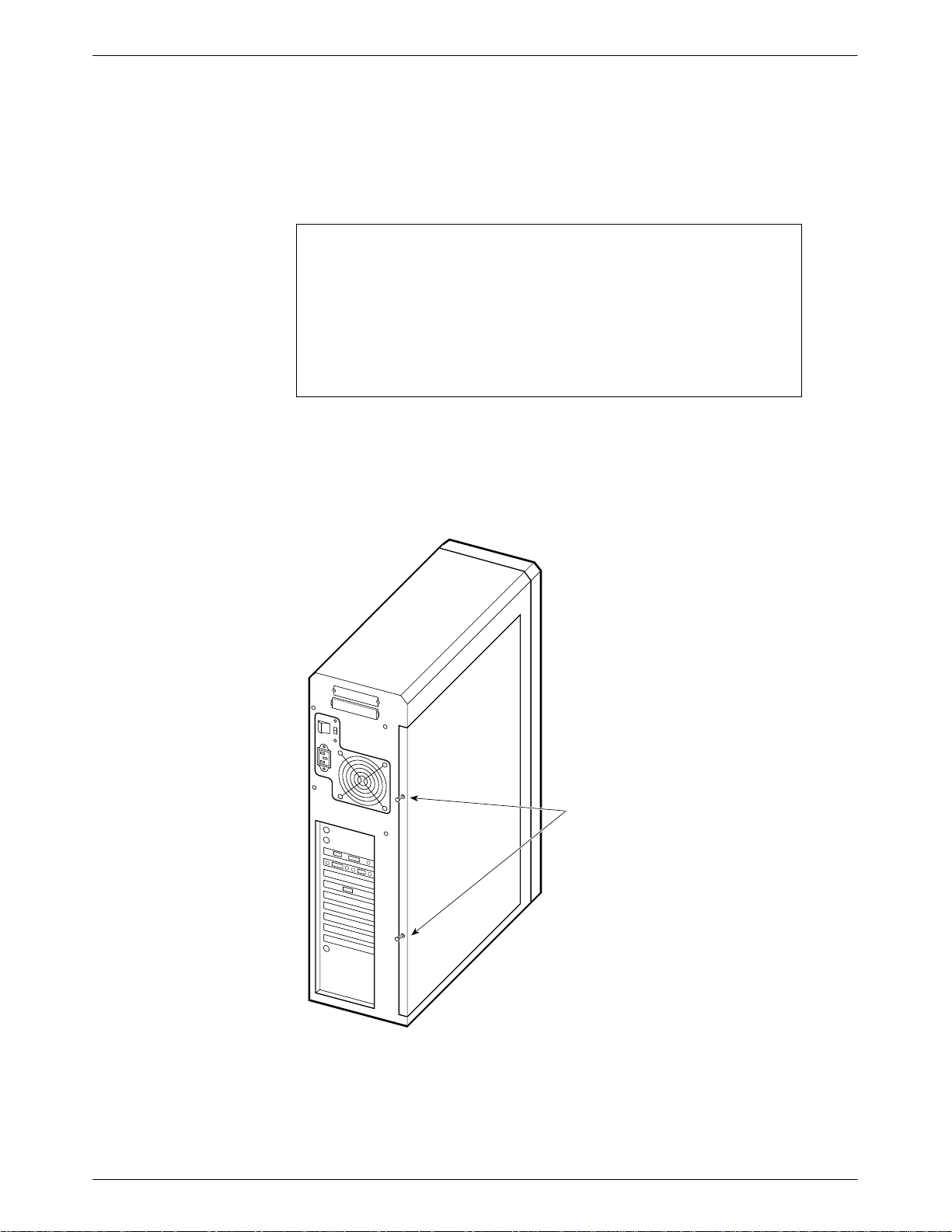
1. Using the # 2 Phillips screwdriver, loosen the two screw-type fasteners (locking pins) that
secure the cover to the chassis. The fasteners are located on the rear panel near the right
side edge, as shown in Figure 2-1.
Preparing the Processors
CAUTION
0
1
Screw-type
Locking Pins
491-13841
Figure 2-1. System 5000 — Cover Fasteners
2-56800-A2-GN22-30 January 1997
Page 29

COMSPHERE 6800 Series Network Management System
2
2. Slide the cover towards the rear about one-half inch to disengage the locking pins, as
shown in Figure 2-2.
3. Lift the cover from the chassis and set it aside.
0
1
491-1384
Figure 2-2. System 5000 — Disengaging Cover Locking Pins
2-6 January 1997 6800-A2-GN22-30
Page 30
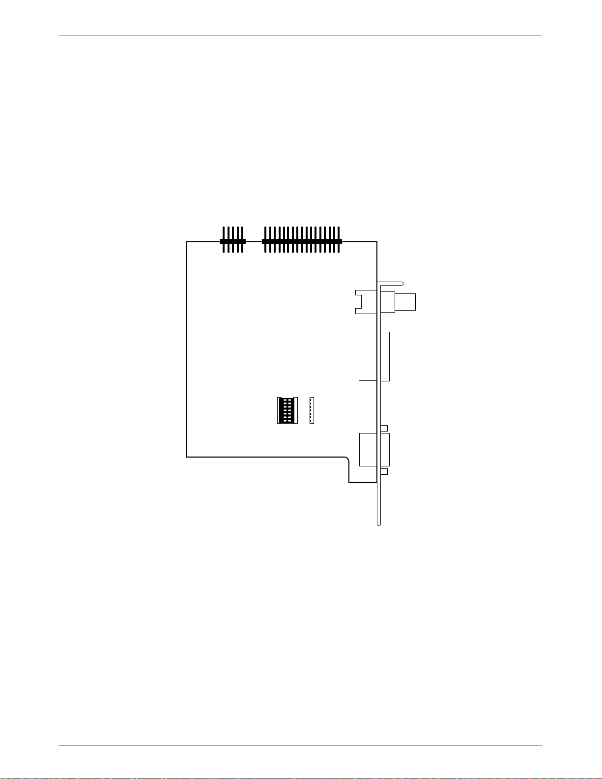
Preinstallation Checks for the Integral Ethernet Card
The Integral Ethernet Card is installed at the factory but the user should check that the settings on
the card are properly configured.
1. Check the jumper settings on the Ethernet card. Confirm that the 7-pin dip jumper is set
between U7 and U8 to set the card for Thick net transmission (see Figure 2-3).
2. Be sure that the Ethernet card is properly seated in the slot above Slot 1 and the cable is
connected to the J5 and J1 pin clusters.
Preparing the Processors
J5
J1
U7 U8 U9
THICK THIN
493-14255
Figure 2-3. Integral Ethernet Card
2-76800-A2-GN22-30 January 1997
Page 31

COMSPHERE 6800 Series Network Management System
Optional Host Upgrade Packages
There are several optional features that the customer can elect to add to the NMS. These features
require the installation of the following Field Upgrade packages at the customer’s location:
ANALYSIS NMS Package
The ANALYSIS NMS package provides cut-through to the ANALYSIS 5600, 5605, and
6510 network management systems. T o communicate with these systems, an AT&T
Intelligent Ports Card Model 900 (IPC-900) must be installed in the host processor.
3270 Emulation Package
The 3270 Emulation package permits a full-feature or basic-feature workstation
connected to the Altos System 5000 host processor to emulate a 3270 terminal and
communicate with a Systems Network Architecture (SNA)-based processor.
16 Control Channel Package
A second DCP/MUXi circuit card for the Altos System 5000 host processor is supported.
This card provides an additional eight control channels for connecting control devices.
Token Ring Package
The Token Ring package provides support for customers with sites where there is an
existing T oken Ring Local Area Network. The Token Ring, thus, would operate in place
of the default Ethernet transport layer and support SNMP trap importation and
cut-through to X11 R4 applications. No preinstallation actions are needed for the Token
Ring Network Interface Card (NIC), but you must install the driver software and run the
EISA Configuration Utility (ECU).
Automatic Backup and Restore Package
The Automatic Backup and Restore package provides support for automatically backing
up and restoring all the NMS database files and directories on a scheduled frequency. This
package requires the installation of a third hard disk on the host. This feature provides the
capability to maintain a “hot spare” system ready to run at short notice.
The ANALYSIS NMS, the 3270 Emulation, and the 16 Control Channel packages for the Altos
System 5000 require the installation of circuit cards in the host processor. The following sections
describe each upgrade package and explain how to configure the strap settings on the circuit cards
and third hard disk. For instructions on installing the circuit cards, see the section entitled Optional
Host Upgrade Procedures.
NOTE
The 16 Control Channel package cannot be installed on the Altos
System 5000 in conjunction with either or both of the ANALYSIS or
3270 Emulation packages.
The Automatic Backup and Restore package consists of both hardware and software installation.
The hardware installation requires installing a third 520 Mb hard disk on the Altos 5000 host
processor with preinstallation steps as well as actually installing the physical drive in the Altos
5000 disk bay. The software portion of this package is documented in the section, Formatting the
Third Hard Disk, in Chapter 5.
2-8 January 1997 6800-A2-GN22-30
Page 32

Preinstallation Steps for the Automatic Backup and Restore Package
To prepare the third hard disk for installation on the System 5000, refer to Figure 2-4 and perform
the following steps:
1. Locate the terminating resistor socket marked CN6 and remove the terminating resistor, if
there is one present. The System 5000 does not use a terminating resistor.
2. Locate the jumper switch block marked as CHN1 and set the jumpers as shown in
Figure 2-4.
3. Locate the jumper switch block marked as CHN7 and set the jumpers as shown in
Figure 2-4. The CHN7 switch block must set the drive’s SCSI ID to 2.
SCSI
ID
1
2
Preparing the Processors
Power
Connection
Data
Connection
CNH7
CNH1
CNH6
494-14505-01
Terminating Resister Socket
(must be empty)
Figure 2-4. Second and Third Hard Disk Jumper Settings
2-96800-A2-GN22-30 January 1997
Page 33

COMSPHERE 6800 Series Network Management System
Preinstallation Steps for the ANALYSIS NMS Package
To configure the IPC-900, refer to Figure 2-5 and follow the instructions below.
1. Set the DIP switch labeled SW1 to the I/O address 2B0.
2. Set the DIP switch labeled SW2 to the memory address D2000.
3. Set the IRQ jumper to IRQ 5.
4. Follow the instructions under Optional Host Upgrade Procedures to install the IPC-900
card in Slot 2.
5. When you have installed all cards in the processor, you must run the EISA Configuration
Utility (ECU) to configure the System 5000’s resources to match all circuit cards in the
system. For instructions on how to run the ECU, refer to the section, EISA Configuration
Utility.
6. You must load the ANALYSIS Gateway software as described in Chapter 5, Loading and
Restoring Software.
SW2SW1
Input/Output
Starting Address
Switch (SW1)
12 345678 12 345678
ON
OFF
Controller Memory
Starting Address
Switch (SW2)
ON
OFF
2B0 D2000
Push Switch
to the Indicated
Position:
Figure 2-5. IPC-900 — Switch and Jumper Locations
IRQ
5
14 7
Interrupt Request (IRQ)
Level Jumper
Set to 5
491-11591a-01
2-10 January 1997 6800-A2-GN22-30
Page 34

Preinstallation Steps for the 3270 Terminal Emulation Package
This upgrade package consists of an Emulex DCP-286i card, and an “octopus” cable assembly that
splits the signal from the board to four individual circuits. T o configure the DCP-286i card, refer to
Figure 2-6 and perform the following steps:
1. Set the DIP switch labeled SW1 to the I/O address 27C.
2. Set the IRQ to 9 by positioning the jumper on the jumper pair labeled 2 on block J6. Block
J6 is on the main card, near the card edge connector below the bottom of the childboard.
Setting the jumper for IRQ 2 is the same as setting the IRQ to 9.
3. Change the settings on block J4 shown in Figure 2-6 to set the local processor block enable
jumper to disable. Move the jumper from block J4 Pins 5 and 3 to Pins 3 and 1.
4. Change the settings on jumper DEF to select 128K window size. Move the jumper from the
E and F pins to the D and E pins. No other jumper changes are required, but you should
confirm that the jumpers on the board match those in Figure 2-6.
5. Follow the instructions under Optional Host Upgrade Procedures to install the DCP-286i
card in Slot 7 and to connect the octopus cable assembly.
Preparing the Processors
6. When you have installed all cards in the processor, you must run the ECU to configure the
System 5000’s resources to match all circuit cards in the system. For instructions on how to
run the ECU, refer to the section EISA Configuration Utility.
7. Refer to the COMSPHERE 6800 Series Network Management System 3270 Terminal
Emulation Option Manual for instructions for loading the software.
2-116800-A2-GN22-30 January 1997
Page 35

COMSPHERE 6800 Series Network Management System
Figure 2-6. Emulex DCP-286i — Switch and Jumper Locations
2-12 January 1997 6800-A2-GN22-30
Page 36

Preinstallation Steps for the 16 Control Channel Package
1
To prepare the DCP/MUXi card for installation in the System 5000 host processor, refer to
Figure 2-7 and perform the following steps:
Preparing the Processors
E3
E43
E 44 E45
E2
E1
E
46
47
E39
E42
E40
E
3
8
E37
E33
E32
E31
E36
E
3
5
E34
29
E28
E
30
E
SW1
494-14511-0
E
E48
E
4
1
Figure 2-7. DCP/MUXi Card
1. Remove two jumpers on the card, one at position E32-E33 (interrupt request) and the other
at position E37-E38 (transparent mode interrupt). You may store a jumper for future use,
such as running diagnostics, by placing it on one pin only.
2. Verify that all other jumpers on the card are in the factory default positions.
3. Verify that the I/O address is set on the card at block SW1 as shown in Table 2-2.
Table 2-2
DCP/MUXi — I/O Address Switch Settings
SWI Description
DCP/MUXi Control Channels 9—16 on on on off
1 2 3 4
2-136800-A2-GN22-30 January 1997
Page 37

COMSPHERE 6800 Series Network Management System
4. When you have installed all cards in the processor, you must run the EISA Configuration
Utility to configure the System 5000’s resources to match the requirements of this circuit
card. For instructions, refer to the section, EISA Configuration Utility.
Preinstallation Checks for the Token Ring Card
The Proteon P1990
All settings are configured using the EISA Configuration Utility.
plus
Network Interface Card requires no jumper or switch settings on the card.
Optional Host Upgrade Procedures
Once you have obtained the appropriate field upgrade package and configured the cards, you are
ready to install the circuit cards in the host processor. The following sections explain how to do
this.
Installing the Third Hard Drive in the System 5000
To physically install the third hard disk drive in the System 5000 chassis (refer to Figure 2-8),
perform the following steps:
1. Attach the 3.5I mounting brackets to the side of the disk drive.
2. Slide the drive into the chassis and attach the 50-pin SCSI bus cable using the next
connector available on the cable.
3. Attach the 5-pin power connector to the disk drive.
4. Insert the screws through the mounting bracket into the front of the chassis. Secure the
drive in the chassis.
2-14 January 1997 6800-A2-GN22-30
Page 38

3rd Hard Drive
Preparing the Processors
Cartridge Tape Drive
Floppy Disk Drive
Figure 2-8. Altos 5000 Disk Bay
Installing Circuit Cards in the System 5000
The System 5000 contains eight EISA expansion slots. Figure 2-9 shows the position of all the
expansion cards within the System 5000 host processor.
Each card should be installed in a specific slot. T able 2-1 gives the proper slot assignments for
each card for the host processor.
To insert the circuit cards into a slot, perform the following steps:
1. Locate the eight EISA slots inside the System 5000 (see Figure 2-9).
2. Take the first circuit card you intend to install and locate the proper slot for that card (see
Table 2-1).
3. Remove the slot cover screw and the slot cover for the slot in which you intend to install
the card. Save the screw for later in this procedure. Save the slot cover in case the circuit
card is removed in the future.
494-14506
2-156800-A2-GN22-30 January 1997
Page 39

COMSPHERE 6800 Series Network Management System
Bracket Holding
Screw
Base I/O Boards
VGA Controller
DCP/MUXi
IPC 1600
Memory Controller
Memory Card
491-13843
Figure 2-9. System 5000 — Expansion Slots
4. Each EISA slot has a connector with two rows of pins. Slide the circuit card in the guides
so that its connector fits into the EISA connector down to the second row of pins.
5. Push once to engage the first row of pins and then again to engage the second row.
6. Repeat this procedure for each circuit card you intend to install.
7. When you have installed all circuit cards, secure each card’s metal bracket to the chassis.
8. When you have installed all circuit cards, you must run the EISA Configuration Utility. See
the section, EISA Configuration Utility , for instructions.
2-16 January 1997 6800-A2-GN22-30
Page 40

Installing the Octopus Cable Assembly
Every host system contains an Emulex DCP/MUXi card. If the 16 Control Channel Package is
installed, two Emulex DCP/MUXi cards are present. An external octopus cable assembly must be
attached to the card at the customer site. Attach the 50-pin connector of the octopus cable to the
connector on the back of the DCP/MUXi card and lock into place. Figure 2-10 shows the
DCP/MUXi and the octopus cable assembly.
Preparing the Processors
Figure 2-10. Emulex DCP/MUCi — Circuit Card and Cable Assembly
2-176800-A2-GN22-30 January 1997
Page 41

COMSPHERE 6800 Series Network Management System
Connecting the Ethernet Card to the Network
The Integral Ethernet card used on most NMS processors requires additional equipment before it
can be connected to the Local Area Network (LAN).
Connect an Allied T elesis 210T transceiver to the Ethernet card’s AUI connector using a 15-pin
Ethernet extender. Connect the transceiver to the LAN’s network hub unit.
Converting Host Processor R3.x to R4.2
The Altos 5000 processor used as a host with 6800 Release 3.x can be migrated as a host under
Release 4.2 by performing the following steps:
1. Backup the Release 3.x user data.
2. Power off the Altos 5000 processor.
3. If a StarLAN card is present, remove it. Replace the slot cover.
4. Ensure that the Ethernet card is properly configured:
5. If the 6800 host processor is to be used with SNMP Manager cut-through, replace the
6. If the 6800 host processor has a DCP286i (3270 Emulation card), reconfigure that card to
7. Replace all processor covers, power up the Altos 5000, and follow the steps for installing
Closing the System 5000
At this point, all the necessary hardware and circuit cards should be installed in the 6800 Series
NMS. The next step in the installation process is to run the EISA Configuration Utility to
configure the internal resources of the System 5000 to match the circuit cards you just installed.
a. Remove the Ethernet card from the unnumbered slot above Slot 1.
b. Check the jumpers at U7 & U8 (See Figure 2-3) to be sure that the card is configured
for THICK NET.
c. Replace the Ethernet card being sure that it is properly seated in its original slot above
Slot 1.
d. Connect the cable to the J5 and J1 pin clusters.
STB Powergraph video card with an ERGO 1 Mb video card, if not already installed.
change the IRQ from 10 to 9 (see Figure 2-6).
the UNIX operating system and NMS Release 4.2 software indicated in Chapter 5, Loading
and Restoring Software.
However, before you can run this program, you must close the System 5000 and attach the power
cable, monitor, mouse and keyboard. To do this, perform the following steps:
1. Slide the cover towards the front of the chassis about one-half inch to engage the locking
pins.
2. Using the # 2 Phillips screwdriver, tighten the two screw-type fasteners that secure the
cover to the chassis. The fasteners are located on the rear panel near the right side edge
(see Figure 2-1).
2-18 January 1997 6800-A2-GN22-30
Page 42

Installing the 16-Port Cabinet Assembly
If you installed an IPC-1600 card in Slot 8 of the host, you will have to connect the card to a
16-port cabinet assembly device that is shipped with the card. T o do this, perform the following
steps:
1. Locate the two 80-conductor ribbon cables and the 16-port cabinet assembly, as shown in
Figure 2-11.
2. Carefully thread the ends of the ribbon cables marked P3 and P4 through the card slot
opening.
3. Connect the cable marked P3 for Ports 9 through 16 to header P3. Connect the cable
marked P4 for Ports 1 through 8 to header P4. The connectors are keyed for proper
alignment with the 80-pin headers on the card, as shown in Figure 2-12. Make sure that the
retaining clips are properly secured.
4. Carefully pass the excess ribbon cable through the slot opening until the IPC-1600 can be
plugged into expansion Slot 8.
Preparing the Processors
Ground
Lug (16)
11109
Cable P3 (Ports 9 – 16)
Cable P4 (Ports 1 – 8)
P4 Connects to P4
Cable P3 (Ports 9 – 16)
P3 Connects to P3
Figure 2-11. 16-Port Cabinet Assembly
12
Turned
180 Degrees
to Show
Connectors
7654321
151413
8
16
Right Side
Wire Frame
Mounting
Slots
491-13022
2-196800-A2-GN22-30 January 1997
Page 43

COMSPHERE 6800 Series Network Management System
P3 or P4
80-Pin Header
Pin 1
Pin 41
Lead 1
Identifier
IPC-1600
Circuit Card
16-Port Ribbon Cable Assembly
Cable P4 Connects to P4 (Ports 1 – 8)
Cable P3 Connects to P3 (Ports 9 – 16)
Pin 40
Pin 80
491-13023
Figure 2-12. 80-Pin Headers P3 and P4 Connector Identification
5. Locate a convenient area to place the cable assembly unit close to the host processor so that
the ports are easily accessible for connecting devices. The cabinet must be located within
about seven cable feet, the length of the fanout module cable assembly, of the host
computer. The cabinet can be installed on the floor or table, or wall mounted.
6. Route the ribbon cables behind the wire-frame assembly of the cabinet with the “lead 1”
identifiers to the left as shown in Figure 2-13. The connectors on the fanout module and the
ribbon cables are keyed for proper alignment. Be sure the retaining clips are properly
secured when connecting the ribbon cables to the fanout module.
7. Connect the ribbon cable nearest the front of the wire-frame assembly to the fanout module
connector for Ports 9 through 16. Next, connect the other ribbon cable for Ports 1 through
8.
8. The fanfold module snaps into the wire-frame assembly from the front of the assembly (see
Figure 2-13). Put the slot on the left side of the fanout module over the wire tab on the left
side of the wire-frame assembly. Next, slide the right side of the fanfold module into the
wire-frame assembly until the two slots on the right of the module engage with the wire
tabs.
2-20 January 1997 6800-A2-GN22-30
Page 44

Preparing the Processors
Figure 2-13. IPC-1600 Ports Cabinet Assembly
Altos System 5000 UIP
The Altos 5000 User Interface Processor (UIP) can connect to either an Altos 5000 or 15000 host.
The UIP memory configurations are different depending on which is the host processor (see
Table 2-4). The Altos 5000 UIP can be configured with an IPC-1600 Serial Ports card and/or a
Proteon P1990plus T oken Ring Network Interface Card. The Token Ring card is optional and
replaces the Integral Ethernet card on the Altos 5000 UIP. The IPC-1600 Serial Ports card is
conditionally optional. That is, it is required on the first UIP of an Altos 15000 NMS but is
optional on an Altos 5000 NMS.
Circuit Cards
Table 2-3 shows the location of the standard and optional circuit cards when installed in the Altos
System 5000 UIP.
2-216800-A2-GN22-30 January 1997
Page 45

COMSPHERE 6800 Series Network Management System
Altos 5000 UIP Factory- and Field-Installable Circuit Cards
Table 2-3
Slot Card
1
3 Video A0000—C7FFF – 46E8,3B0—3DF Provides VGA-level graphics.
6 Proteon ProNet
8 IPC-1600 E10000—E1FFFF 11 110—11F Optional. Provides 16 serial ports.
* The IPC-1600 is required on UIP-1 with Altos 15000 host.
Base I/O — — 1000—101F Controls the hard disk(s), floppy
Integral
Ethernet
Token Ring
Card
Memory
Address
— 10 1CD0—1CD2 Supports connection to host, full-
— 10 — Optional. Provides support for
IRQ I/O Address Description
disk and cartridge tape drives.
feature workstations. Incompatable
with Token ring card.
Token Ring local area network
communication with hosts and fullfeature workstations. Incompatible
with Integral Ethernet.
Opening the Altos 5000 UIP
The procedures for opening the System 5000 UIP are the same as for the System 5000 host. Refer
to the section, Opening the System 5000 Host, for precise instructions.
Installing Additional Memory on the System 5000
The UIP shipped with Release 4.2 has 32 megabytes of memory. If that UIP is connected to an
Altos 15000 host, it requires an additional 16 megabytes. Upgrading from a prior release of NMS
may also require additional memory to be installed (see T able 2-4).
To upgrade the memory on the Altos 5000 UIP, you must have a Single Inline Memory Module
(SIMM) package, part no. 555-24231-003, which contains four 4 megabyte SIMMs. Converting
from prior NMS releases may require more than one SIMM package.
Install the additional SIMMs, one SIMM in each of the four memory banks on the card,
immediately next to those SIMMs already installed. If the SIMMs are not adjacent to each other in
each bank or a memory bank has no SIMMs installed, the processor cannot power up properly.
To install the memory on the UIP, perform the following steps:
1. If the processor is running, stop the NMS processes and shut down UNIX by following the
steps in the applicable sections of Chapter 6, System Start-up and Shutdown.
2. When the message Safe to power off appears, power down the processor using the on/off
switch.
3. Remove the side cover, exposing the installed boards.
2-22 January 1997 6800-A2-GN22-30
Page 46

Preparing the Processors
4. Remove the memory board by unscrewing the hold-down screw on the board in memory
Slot 0 located at the bottom of the processor; gently pull the board until it is free of the slot.
Place the board on a flat surface with its memory plug facing you.
5. Each of the four memory banks on the board should already have a memory SIMM
installed in the first and second positions. Install each of the new 4 megabyte SIMMs as
follows:
a. Hold the SIMM over the SIMM socket on the memory board with the SIMM’s “key
notch” located at the bottom and facing opposite the memory plug. This is the only
way the SIMM can fit into the socket.
b. Firmly press the SIMM into the socket.
c. When the SIMM is seated properly in the socket, tilt it back with the pegs showing
through the guide holes; press firmly until it snaps into place with the plastic arms on
each side of the socket holding it securely.
CAUTION
If any difficulty is encountered in fitting the SIMM into the
socket, getting the guide pegs into the guide holes on the
SIMM, or snapping the plastic arms securely in place, you may
have the SIMM facing the wrong direction, or it may be the
wrong part.
6. Reinstall the memory board into memory Slot 0 in the processor from which it was
removed by gently pushing it back until it is firmly seated in the slot.
7. Screw the hold-down screw back into the processor.
8. Replace the processor side cover, tighten down the screws, and power on the processor
with the on/off switch.
9. When the system boots, the following messages appear:
Invalid configuration information - please run SETUP program
Select [1] to boot from Hard Disk
Select [2] to boot from Floppy
Select [3] to boot from Tape Select
[4] to enter BIOS setup
Enter option:
TYPE: 4
2-236800-A2-GN22-30 January 1997
Page 47

COMSPHERE 6800 Series Network Management System
10. The following messages appear:
Errors have been found during the power on self test in your computer. The
errors were:
Incorrect configuration data in CMOS Memory size in CMOS invalid
SETUP will attempt to correct these errors through auto configuration.
Hit any key to continue.
PRESS: Enter
11. The main SETUP screen appears.
PRESS: Esc
The system reboots.
12. At the prompt,
Boot
.
.
turn off the machine.
Preinstallation Checks for the Integral Ethernet Card
The Integral Ethernet card is installed at the factory but the user should check that the settings on
the card are properly configured.
1. Check the jumper settings on the Ethernet card. Confirm that the 7-pin dip jumper is set
between U7 and U8 to set the card for Thick net transmission (see Figure 2-3).
2. Be sure that the Ethernet card is properly seated in the unnumbered slot above Slot 1 and
the cable is connected to the J5 and J1 pin clusters.
2-24 January 1997 6800-A2-GN22-30
Page 48

Optional UIP Upgrade Packages
Several optional packages can be added to the Altos System 5000 User Interface Processor (UIP).
These packages are installed at the customer’s location.
Serial Port Upgrade Package for the UIP
The AT&T Intelligent Ports Card Model 1600 (IPC-1600) provides the UIP with 16 extra
serial ports to connect to basic-feature workstations or external devices. These ports are
housed in an external cable assembly device that connected to the IPC-1600 card. If the
customer has a large network, this package may be a necessity.
This package is optional for a UIP connected to an Altos 5000 host. An IPC-1600 must be
installed on the first UIP which is connected to an Altos 15000. This installation is
performed at the customer site.
Token Ring Package
The Token Ring package provides support for customers with sites where there is an
existing T oken Ring Local Area Network. The Token Ring package replaces the standard
Ethernet transport layer and supports SNMP trap importation and cut-through to X11 R4
applications. No preinstallation actions are needed for the T oken Ring Network Interface
Card, but you must install the driver software and run the EISA Configuration Utility.
Preparing the Processors
2-256800-A2-GN22-30 January 1997
Page 49

COMSPHERE 6800 Series Network Management System
Preinstallation Steps for the IPC-1600 Upgrade Card
To configure the IPC-1600 card, refer to Figure 2-14 and perform the following steps:
1. On the bank labeled DS1, set the memory address to E10000 with switches 1 through 8.
2. On the bank labeled DS1, set the I/O address to 110 with switches 9 through 11.
3. On the bank labeled DS2, set the IRQ to 11 with switches 1 through 8.
4. On the jumper labeled J1, check that the jumper is on Pins 2 and 3 to set the local program
memory to 16 kb.
5. Follow the instructions under Field Upgrade Procedures to install the IPC-1600 card in
Slot 8 of the UIP.
6. Once you have installed the card, you must run the EISA Configuration Utility to configure
the System 5000’s resources to match the requirements of this circuit card. For instructions,
see the section entitled EISA Configuration Utility.
Local Program
Memory Size Select
Jumper (J1)
J1
7. You must reload the UIP software to specify that the IPC-1600 has been installed (see
Chapter 5, Loading and Restoring Software, for details).
Ribbon Cable Connections
P3 (Ports 9 – 16)
and
P4 (Ports 1 – 8)
DS1 DS2
P3
P4
PIN 1
DS1
11 10 9 87654321
ON
OFF
110 E10000
ON
OFF
DS2
87654321
IRQ 11
Push Switch to the
Indicated Position:
491-13021-02
Figure 2-14. IPC-1600 — Switch and Jumper Locations and Settings
2-26 January 1997 6800-A2-GN22-30
Page 50

Preinstallation Checks for the Token Ring Card
The Proteon P1990
All settings are configured using the EISA Configuration Utility.
plus
Network Interface Card requires no jumper or switch settings on the card.
Optional UIP Upgrade Procedures
Once you have obtained the desired field upgrade package and prepared it for installation, you can
then install the circuit card(s) in the UIP. The procedures for installing circuit cards in the UIP are
the same as those for installing in the Altos System 5000 host processor. Refer to the sections,
Installing Circuit Cards in the System 5000 and Closing the System 5000.
Converting Altos 5000 Processors to Release 4.2 UIPs
Altos 5000 processors from previous releases of NMS can be converted to UIPs for Release 4.2
NMS. The steps taken depend on what use the System 5000 had under the previous NMS and how
it will be used with Release 4.2. T able 2-4 describes the major actions to be taken when converting
a “Source” system to a 4.2 UIP.
Preparing the Processors
Source System
R3.1 Altos 5000 host with
32 Mb and StarLan
R3.1 Altos 5000 UIP with
16 Mb and StarLan
R4.1 Altos 5000 host with
32 Mb and Ethernet
R4.1 Altos 5000 UIP with
32 Mb and Ethernet
Table 2-4
Altos 5000 UIP Conversion Matrix
T arget System
4.2 UIP Connected To
Altos 5000 Host
N/A
Add 16 Megabytes memory
Remove StarLan card and check
Integral Ethernet card
N/A
No changes required.
4.2 UIP Connected To
Altos 15000 Host
Add 16 Megabytes memory
Remove StarLan card and check
Integral Ethernet card
Add 32 Megabytes memory
Remove StarLan card and check
Integral Ethernet card
Add 16 Megabytes memory
Add 16 Megabytes memory
2-276800-A2-GN22-30 January 1997
Page 51

COMSPHERE 6800 Series Network Management System
UIP Conversion Procedures
The following steps describe the actions to be taken in converting an Altos 5000 host processor
from a previous release of NMS to Release 4.2:
1. Backup the previous release database and user files.
2. Power off the Altos 5000 processor and remove the processor covers.
3. Remove the DCP-286i (3270 Emulation package), IPC-900 (ANALYSIS NMS package),
and DCP-MUXi (16 Control Channel package) cards, if any of them are installed in the
processor . The DCP-MUXi can be reused in the new host processor. The DCP-286i and
IPC-900 can only be used in an Altos 5000 host.
4. If an IPC-1600 card is present and it is being transferred to the host processor, remove it
now. If an IPC-1600 card is present and is being used in the UIP, do not remove it or
modify it. The strap settings are correct.
5. If a StarLAN NAU card is present, remove it from the processor. Check the Integral
Ethernet card referring to the sections, Preinstallation Checks for the Integral Ethernet
Card and Connecting the Ethernet Card to the Network.
6. Upgrade the memory as indicated in Table 2-4. Refer to the section, Installing Additional
Memory on the System 5000 UIP.
7. Replace all processor covers, reboot and run the EISA Configuration Utility, and follow the
steps for installing the UNIX operating system and the UIP Release 4.2 software as
indicated in Chapter 5, Loading and Restoring Software.
Connecting the Ethernet Card to the Network
The Integral Ethernet card used on most NMS processors requires additional equipment before it
can be connected to the Local Area Network (LAN).
Connect an Allied T elesis 210T transceiver to the Ethernet card’s AUI connector using a 15-pin
Ethernet extender. Connect the transceiver to the LAN’s network hub unit.
Closing the Altos 5000 UIP
The procedures for closing the Altos 5000 UIP are the same as those for the 5000 host. Refer to the
section, Closing the System 5000, for precise instructions.
2-28 January 1997 6800-A2-GN22-30
Page 52

Installing the 16-Port Cabinet Assembly
If you installed an IPC-1600 card in Slot 8 of the UIP, you will have to connect the card to a
16-port cabinet assembly device that is shipped with the card. T o do this, perform the following
steps:
1. Locate the two 80-conductor ribbon cables and the 16-port cabinet assembly, as shown in
Figure 2-11.
2. Carefully thread the ends of the ribbon cables marked P3 and P4 through the card slot
opening.
3. Connect the cable marked P3 for Ports 9 through 16 to header P3. Connect the cable
marked P4 for Ports 1 through 8 to header P4. The connectors are keyed for proper
alignment with the 80-pin headers on the card, as shown in Figure 2-12. Make sure that the
retaining clips are properly secured.
4. Carefully pass the excess ribbon cable through the slot opening until the IPC-1600 can be
plugged into expansion Slot 8.
Preparing the Processors
5. Locate a convenient area to place the cable assembly unit close to the host processor so that
the ports are easily accessible for connecting devices. The cabinet must be located within
about seven cable feet, the length of the fanout module cable assembly, of the host
computer. The cabinet can be installed on the floor or table, or wall mounted.
6. Route the ribbon cables behind the wire-frame assembly of the cabinet with the “lead 1”
identifiers to the left as shown in Figure 2-13. The connectors on the fanout module and the
ribbon cables are keyed for proper alignment. Be sure the retaining clips are properly
secured when connecting the ribbon cables to the fanout module.
7. Connect the ribbon cable nearest the front of the wire-frame assembly to the fanout module
connector for Ports 9 through 16. Next, connect the other ribbon cable for Ports 1 through
8.
8. The fanfold module snaps into the wire-frame assembly from the front of the assembly (see
Figure 2-13). Put the slot on the left side of the fanout module over the wire tab on the left
side of the wire-frame assembly. Next, slide the right side of the fanfold module into the
wire-frame assembly until the two slots on the right of the module engage with the wire
tabs.
2-296800-A2-GN22-30 January 1997
Page 53

COMSPHERE 6800 Series Network Management System
Altos System 15000
The Altos System 15000 is based on the EISA bus, featuring two Intel i80486 processors running
at a clock speed of 50 Mhz. The following section describes the hardware and circuit cards that
may be installed in the System 15000.
Hardware
The System 15000 is shipped to the customer with the processor, three memory modules, two hard
disks, one CPU, two Emulex DCP/MUXi cards, and one IPC-1600 card.
Circuit Cards
Table 2-5 indicates the location of the standard and optional circuit cards installed in the System
15000. Preinstallation checks for the Ethernet card are the same for the System 15000 as for the
System 5000.
Table 2-5
Altos 15000 Factory- and Field-Installable Circuit Cards
Slot
2 IPC-1600 F00000—F0FFFF
4 Emulex DCP/
5 Emulex DCP/
6 ECA — 10 6C80—6CAF Supports Ethernet connection to the
8 SCSI Controller — 14 8C80—8CAF Controls the hard disk(s), floppy disk,
9 Video A0000—C7FFF 9 3B0—3DF
Card
MUXi
MUXi
Memory
Address
(15m)
DC000—DFFFF — 33C—33F Provides eight control channels that
D8000—DBFFF — 23C—23F Provides a second set of eight control
IRQ I/O Address Description
11 110—11F Provides 16 serial ports. Field
installed.
monitor modem and DSU networks.
Field installed.
channels for monitoring networks.
Field installed.
UIP and the full-feature workstation.
and cartridge tape drive.
Provides VGA-level graphics.
(Multiple)
2-30 January 1997 6800-A2-GN22-30
Page 54

Opening the System 15000
To open the Altos System 15000 and install circuit cards, perform the following steps:
1. Slide the top cover towards the rear of the chassis approximately .75I, as shown in
Figure 2-15, until the locking pins on the underside of the cover disengage. Lift the cover
straight up and set it aside.
Preparing the Processors
CAUTION
1. Make sure the ac power cord is not connected to the System
15000 before opening the computer and attempting to perform
any field installation activity.
2. To prevent static discharge that may damage the hardware,
wear a ground strap or otherwise ground yourself to the
chassis before opening the computer and installing any circuit
cards.
2-316800-A2-GN22-30 January 1997
Page 55

COMSPHERE 6800 Series Network Management System
494-14500-01
Figure 2-15. System 15000 — Removing the Top Cover
2. Slide the right-hand side cover upwards about 1I and swing the cover outwards pivoting
on the rear edge, as shown in Figure 2-16.
3. Disengage the rear edge of the right side cover and lift it from the chassis and set it aside.
4. Remove the left side cover by lifting it by the fingerhold built into the top portion of the
cover and set the cover aside.
5. Open the door on left front of the chassis and remove the two Phillips-head screws just
inside the hinge (see Figure 2-17). Save the screws for later.
6. Disengage the door spring from the pin on the lower pivot of the door hinge.
7. Remove the left side cover by lifting it by the fingerhold built into the top portion of the
cover and set the cover aside.
2-32 January 1997 6800-A2-GN22-30
Page 56

2. Panel swings out
Preparing the Processors
1. Panel slides up 1"
494-14501
Figure 2-16. System 15000 — Removing the Side Panel
2-336800-A2-GN22-30 January 1997
Page 57

COMSPHERE 6800 Series Network Management System
Figure 2-17. System 15000 — Removing the Front Panel
494-14581
2-34 January 1997 6800-A2-GN22-30
Page 58

Installing the MPX Processor
1
The Altos 15000 supports up to four 486/50 modules. These modules are attached to the main
processor card (see Figure 2-18) which plugs into S-bus slots on the motherboard (see
Figure 2-19). The Altos 15000 is shipped with one processor present. The second CPU module
must be installed at the customer site.
The Altos 15000 has four S-bus slots next to the ten general purpose slots. These S-bus slots are
the four unnumbered slots at the front of the Altos 15000 system unit. These slots hold the CPU
board and memory boards and each slot is limited to a particular type of board. S-bus Slot 1 is the
front-most slot and contains the CPU board holding both CPUs. S-bus Slot 4 is the fourth slot in
from the front and contains the memory board (see Figure 2-19).
Prior to installing the MPX, you must have the following parts:
• Intel486t DX CPU-CACHE Module
• Five hexagonal separator posts approximately 7/16I long
• Three hexagonal nuts 1/8I in diameter
• Five Phillips-head screws approximately 3/16I long
Preparing the Processors
J1 J2
J5
Figure 2-18. Altos 15000 Main Processor Card and MPX
J2
494-14507-0
2-356800-A2-GN22-30 January 1997
Page 59

COMSPHERE 6800 Series Network Management System
Main Processor
Card Slot
Memory
Board
Slot
S-bus
Slots
1 2 3 4
494-14508-01
Figure 2-19. Altos 15000 Motherboard and Bus Connectors
To install the MPX module, perform the following steps:
1. Using a Phillips screwdriver, remove the screw from the card’s metal bracket. Save the
screw for later use. Gently disengage the card’s bus connectors from S-bus Slot 1 and slide
the card out of the chassis.
2. On the MPX module (see Figure 2-18), screw two separator posts into the top middle and
top right holes in the card. Attach the remaining three separator posts to the top left, bottom
left, and bottom right holes on the MPX module using the hexagonal nuts provided.
3. Make sure that the jumper at J5 (see Figure 2-18) on the main processor card is placed on
Pins 2 and 3 to indicate that two CPUs are present.
4. Position the MPX module with its connector mating with the J2 connector (see
Figure 2-18) on the main processor card and press firmly until the connector is fully seated.
2-36 January 1997 6800-A2-GN22-30
Page 60

5. From the other side of the main processor card, attach the MPX module to the main
processor card using the Phillips-head screws.
6. Slide the main processor card into its original slot in the chassis and press firmly until the
card is fully seated.
7. Attach the main processor card metal bracket to the chassis with the saved screw.
Installing the Second and Third Hard Disks on the System 15000
Installation of the second and third hard disks on the System 15000 consists of three parts:
• Preinstallation – setting and verifying switches on the drive
• Installing the drive in the System 15000 chassis
• Formatting the disk and establishing the file systems
The first two parts are documented in the following sections. The last part is described in the
section, Formatting the Third Hard Disk in Chapter 5. The second hard disk is automatically
formatted as part of installing UNIX.
Preparing the Processors
Preinstallation Steps for the Second and Third Hard Disks on the System 15000
To prepare the second and third hard disks for installation on the System 15000, refer to Figure 2-4
and perform the following steps:
1. Locate the terminating resistor socket marked as CN6 and remove the terminating resistor,
if there is one present. The System 15000 does not use a terminating resistor.
2. Locate the jumper switch block marked as CHN1 and set the jumpers as shown in
Figure 2-4.
3. Locate the jumper switch block marked as CHN7 and set the jumpers as shown in
Figure 2-4. The CHN7 switch block sets the drive’s SCSI ID. The second hard disk must
have an ID of 1; the third must be 2.
2-376800-A2-GN22-30 January 1997
Page 61

COMSPHERE 6800 Series Network Management System
1
Installing the Second and Third Hard Disks in the System 15000
To physically install the second and third hard disks in the System 15000 chassis, refer to
Figure 2-20 and perform the following steps for each disk:
1. Attach the 3.5I mounting brackets to the side of the disk.
2. Slide the drive into the chassis and attach the SCSI bus ribbon cable using the next
connector available on the cable to the 50-pin connector on the drive.
3. Attach the power connector to the 4-pin connector on the drive.
4. Push the drive into the chassis until it is fully seated and the mounting brackets lock in the
chassis.
3rd Hard
Drive
2nd Hard
Drive
1st Hard
Drive
Figure 2-20. Altos 15000 Showing the Hard Disk Bay
494-14509-0
2-38 January 1997 6800-A2-GN22-30
Page 62

Installing Additional Memory on the System 15000
Running the NMS requires 64 Mb of memory on the System 15000. The 15000 comes with one
16-Mb module installed. Three additional 16-Mb modules must be installed on the memory board
(see Figure 2-21).
If all four memory modules are not available or working, you may, on
a temporary emergency basis, have to use fewer than four. The
memory banks must be filled in sequence starting with Bank 1
upwards.
Preparing the Processors
NOTE
Bank 1Bank 3
Bank 2Bank 4
494-14510
Figure 2-21. Altos 15000 Memory Board and Memory Modules
To install the three memory modules, refer to Figure 2-21 and perform the following steps:
1. Using a Phillips screwdriver, remove the memory board from S-bus Slot 4 by unscrewing
the board’s metal bracket from the chassis and sliding the board out. Save the screw for
later.
2. Position each memory module with the connector just meeting the pins on the board. Be
careful not to bend any pins. Press firmly until the module is properly seated.
2-396800-A2-GN22-30 January 1997
Page 63

COMSPHERE 6800 Series Network Management System
NOTE
The memory module can be installed in two possible ways. The
correct way does not interfere with either the metal bracket on the
board or any other memory module. If you have any such contact
between modules or with the metal bracket, gently remove the
module, reverse it and reinstall.
3. Slide the memory board into the slot from which it came ensuring that the board’s
connectors are firmly seated in the bus slots.
4. Using the saved screw, reattach the memory board’s metal bracket to the chassis.
Preinstallation Steps for the IPC-1600 Card on the System 15000
To configure the IPC-1600 card, refer to Figure 2-14 and perform the following steps:
1. On the bank labeled DS2, set the IRQ to 11 with switches 1 through 8.
2. On the bank labeled DS1, set the I/O address to 110 with switches 9 through 11.
3. On the bank labeled DS1, set the memory address to F00000 (see Table 2-6) with switches
1 through 8.
Table 2-6
IPC-1600 — Memory Switch Settings (DSI)
Switches
ON X X X X
OFF X X X X
8 7 6 5 4 3 2 1
2-40 January 1997 6800-A2-GN22-30
Page 64

4. On the jumper labeled J1, check that the jumper is on Pins 2 and 3 to set the local program
memory to 16 Kb.
5. Follow the instructions under Installing Circuit Cards in the System 15000 to install the
IPC-1600 card in Slot 2 of the System 15000.
Preinstallation Steps for the DCP-MUXi Cards on the System 15000
To prepare the DCP-MUXi cards for installation on the System 15000, refer to Figure 2-7 and
perform the following steps:
1. Remove two jumpers from each card, the first at position E32-E33 (interrupt request) and
the second at position E37-E38 (transparent mode interrupt). You may store a jumper for
future use, such as running diagnostics, by placing it on one pin only.
2. Verify that all other jumpers on the cards are as shown in Figure 2-7.
3. On the block SW1, set the I/O addresses as shown in Table 2-7.
Preparing the Processors
Table 2-7
DCP-MUXI — I/O Address Switch Settings
Description 1 2 3 4
DCP-MUXI #1 (Slot 4) on on off off
DCP-MUXI #2 (Slot 5) on on on off
4. Follow the instructions under Installing Circuit Cards in the System 15000 to install the
DCP-MUXi cards in Slots 4 and 5 of the System 15000.
2-416800-A2-GN22-30 January 1997
Page 65

COMSPHERE 6800 Series Network Management System
Installing Circuit Cards in the System 15000
The System 15000 contains eight EISA expansion slots. Figure 2-22 shows the position of all the
expansion slots within the System 15000 processor chassis. Each card should be installed in a
specific slot. T able 2-5 gives the proper slot assignment for each card.
Slot Cover
Screw
IPC-1600
First DCP/MUXi
Second DCP/MUXi
ECA Card
Video Card
Figure 2-22. System 15000 — Expansion Slots
To insert the circuit cards into a slot, perform the following steps:
494-14502-01
1. Locate the EISA slots inside the System 15000 (see Figure 2-22).
2. Take the first circuit card you intend to install and locate the proper slot for that card (see
Table 2-5).
3. Using a Phillips screwdriver, remove the slot cover screw and the slot cover for the slot in
which you intend to install the card. Save the screw for later. Save the slot cover in case the
card is removed in the future.
2-42 January 1997 6800-A2-GN22-30
Page 66

4. Slide the circuit card in the guides so that its connector fits into the EISA connector.
5. Press firmly but carefully to engage the connector pins.
6. Repeat this procedure for each circuit card you intend to install.
7. When you have installed all circuit cards, secure the card’s metal bracket to the chassis
with the screw saved from Step 3.
Closing the System 15000
When all the necessary hardware and circuit cards are installed in the Altos System 15000, the
EISA Configuration Utility (ECU) must be run to configure the internal resources of the processor
to match the circuit cards physically installed. Before running the ECU, you must close the System
15000 and attach the power cable, monitor, mouse, and keyboard. To close the System 15000,
perform the following steps:
1. Replace the front cover ensuring that the top and side clips are properly engaged.
Preparing the Processors
2. Re-connect the door spring to the pin at the bottom of the door hinge.
3. Reattach the two Phillips-head screws inside the door hinge.
4. Replace the left side cover.
5. Hook the right side cover rear edge around the end of the chassis with the cover at about a
30-degree angle out from the chassis.
6. Swing the right side cover inward towards the chassis and slide it down until the bottom
edge locks in place.
7. Place the top cover on the chassis, making sure that the locking pins on the cover underside
are positioned in the locking slots. Slide the cover towards the front of the chassis until the
locking pins (see Figure 2-23) engage.
NOTE
The Altos System 15000 will not power on unless the top cover is
fully engaged.
2-436800-A2-GN22-30 January 1997
Page 67

COMSPHERE 6800 Series Network Management System
Top Cover
Locking Pins
494-14503
Figure 2-23. System 15000 — Top Cover Locking Pins
2-44 January 1997 6800-A2-GN22-30
Page 68

Running CMOS Setup on the Altos 15000
Once the circuit cards are configured and installed, the system date and time and memory ranges
for add-on cards should be set. This procedure requires the system to be restarted using the
following steps:
1. Power on the system and repeatedly
PRESS: Ctrl-Alt-Esc
2. The BIOS Setup Utility menu appears. Using the ↓↑ keys, select System Configuration
Setup and
PRESS: Enter
PRESS: Page Down
3. Page 1 of the System Configuration will appear. Using the ↓↑ keys, select the correct date
and time.
4. Page 2 of the System Configuration appears. At the bottom of the page is a field, Memory
0F00000H:0FFFFFFH. Using the ←/→ keys, change the value System to Add-on Card.
Preparing the Processors
PRESS: Esc
5. A confirmation box appears; to save the CMOS data,
PRESS: Enter
6. The main BIOS Setup Utility menu appears.
PRESS: Esc
7. The system automatically reboots.
2-456800-A2-GN22-30 January 1997
Page 69

COMSPHERE 6800 Series Network Management System
EISA Configuration Utility
The EISA Configuration Utility (ECU) is a program that is shipped with the 6800 NMS
Applications software package and used to configure the System 5000 and System 15000 so that
their resources match the requirements of the circuit cards you installed. The ECU is shipped on a
floppy disk with separate disks for the System 5000 host, System 15000 host, and UIP.
To ensure that these cards function properly, you must run this program as soon as you have
finished installing the cards in either the host or the UIP.
To run the ECU, you must connect the display unit, keyboard, and
mouse. For instructions, turn to the section entitled
in Chapter 4,
The EISA Configuration Disk contains the ECU program and configuration files. These
configuration files describe all the circuit cards that could be installed on the Altos System 5000 or
System 15000. T able 2-8 shows the names of the configuration files depending on the type of
processor you have and the type of network connected to the processor.
NOTE
Connecting the Components
System Console
.
Table 2-8
Configuration Files
Diskette Title
6800 NMS ECU
6800 UIP ECU
6800 NMS ECU (15000) System 15000 Ethernet 680015.SCI
Processor Network Type File Name
System 5000 Host Ethernet 68005E.SCI
System 5000 Host Token Ring 68005T.SCI
System 5000 UIP Ethernet 68005EU.SCI
System 5000 UIP Token Ring 68005TU.SCI
NOTE
"
" !
" " # "
# "
"
#
2-46 January 1997 6800-A2-GN22-30
Page 70

Preparing the Processors
6
The EISA Configuration Disk is a bootable disk. T o run the program, you will need to boot the
processor with this disk. T o do this, perform the following steps:
1. Insert the EISA Configuration Disk into the floppy disk drive. Turn the power switch to the
ON position. (If the RESET/RUN switch is not in the RUN position, turn the key
clockwise until it is in the RUN position.) The system begins to boot. If you are running
the ECU on a System 15000, go to Step 3. The system briefly displays the following
message:
Press spacebar to interrupt autoboot
NOTE
You have approximately 10 seconds to press the spacebar to
interrupt the autoboot sequence and allow booting from the floppy
disk. Failure to do this within the 10-second window allows the
system to start up from the hard disk and requires a reboot.
2. Immediately press the spacebar. The boot menu appears, as shown in Figure 2-24.
TYPE: 2
to select boot from floppy.
Select [1] to boot from hard disk
Select [2] to boot from floppy
Select [3] to boot from tape
Select [4] to enter BIOS setup
Enter option:
Figure 2-24. Boot Menu
3. Press any key to dismiss the EISA logo and display the Welcome screen. Then,
PRESS: Enter
to display the Main Menu. It is shown in Figure 2-25.
491-1383
2-476800-A2-GN22-30 January 1997
Page 71

COMSPHERE 6800 Series Network Management System
1
Main Menu
Learn about configuring your computer
Configure computer
Set date and time
Exit from this utility
4. Use the ↓ key to highlight Configure computer and
PRESS: Enter
491-13837
Figure 2-25. Main Menu
The Configure Computer Menu displays, as shown in Figure 2-26.
Configure Computer
Copy configuration (CFG) files
Configure computer-basic method
Configure computer-advanced method
Return to the main menu
Figure 2-26. Configure Computer Menu
5. Use the ↓ key to highlight Configure computer-advanced method and
PRESS: Enter
The Configuration files are loaded and verified. The program then presents a screen
showing your current configuration.
494-13838-0
PRESS: Alt + s (for “System”)
6. Use the ↓↑ keys to highlight Open and
PRESS: Enter
2-48 January 1997 6800-A2-GN22-30
Page 72

The following messages appear.
Current configuration information will be lost
if you continue.
Select <Ok> to continue or select <Cancel>
to return to previous screen
7. Select <Ok> using the →/← keys and
PRESS: Enter
A list of configuration files appears. Refer to T able 2-8 for possible file names and
applicable configurations.
8. Use the ↓↑ keys to select the proper configuration file and
PRESS: Enter
The following messages appear.
Loading configuration files
Please wait . . .
Preparing the Processors
The maximal configuration of circuit card descriptions and settings will be automatically
loaded. Use the ↓↑ keys to review the cards in the loaded configuration. Delete any cards
that you do not have installed on the system. T o delete a card configuration, highlight the
card description on the screen using the ↓↑ keys and press the Delete key.
9. To verify that all resources have been correctly configured:
PRESS: Alt + v (for “view”)
PRESS: r (for “Resources”)
to display the Resource Map. This display lists the settings for each component of the
system. Use the ↓↑ keys to scroll through the Resource Map and verify that all appropriate
settings are correct. Refer to T able 2-1 for Altos 5000 host, Table 2-3 for Altos 5000 UIP,
and T able 2-5 for Altos 15000 host.
If the settings are correct,
PRESS: Enter
PRESS: Alt +s (for “System”)
PRESS: x (for “exit”)
to exit. Select Save configuration and exit by pressing the s key when prompted. Reboot
the system to allow the new settings to take effect. Remove the EISA Configuration Disk
from the floppy drive and store it safely.
NOTE
At any time in running the ECU, you may reload the configuration
file, which contains the correct settings and begin again the process
of deleting those circuit card descriptions which are not installed. To
do this, press Alt + s (for “System”) and go to Step 6.
2-496800-A2-GN22-30 January 1997
Page 73

COMSPHERE 6800 Series Network Management System
Changing the Token Ring Configuration
The Token Ring package configuration can be changed using the ECU to specify 4 Mbps speed
and/or shielded cable. You should execute the ECU normally and follow the steps specified above
through Step 8. Continue with the following steps:
1. To view all configured resources and display the Detailed Slot Map:
PRESS: Alt + v
TYPE: d
2. The Detailed Slot Map lists the setting for each component of the system. Use the ↓↑ keys
to scroll down to Slot 6 to see the T oken Ring card configuration and to highlight the
Interrupt field values.
PRESS: Enter
3. A Change Function Menu appears. Use the ↓↑ keys to select IRQ 10 Edge Triggered.
PRESS: Enter
4. The Detailed Slot Map again appears. Use the keys to highlight the Speed field values.
PRESS: Enter
5. A Change Function Menu appears. The speed is set to 16 Mbps. Use the ↓↑ keys to select
4 Mbps if your LAN runs at this speed.
PRESS: Enter
6. The Detailed Slot Map again appears. Use the ↓↑ keys to highlight the Media Type field
values.
PRESS: Enter
7. A Change Function Menu appears. The Media Type is set to unshielded. Use the keys to
select Shielded (STP) cable if that cable type has been physically connected from the
Token Ring card to the Multi-Access Unit (MAU).
PRESS: Enter
8. To exit from this configuration function,
PRESS: Alt + Enter
TYPE: x
Select Save configuration and exit by pressing the s key.
9. The following message appears.
Your configuration has been saved. If you need to change any switch or
jumper setting or install any boards and options, turn off your computer
and do so right now. If not, Press [Enter] to reboot (restart) your system.
PRESS: Enter
The system reboots.
2-50 January 1997 6800-A2-GN22-30
Page 74

Full-Feature Workstation
Preinstallation Checks for the EtherLink II Card
The 3COM EtherLink II Card is installed at the factory for workstations from Paradyne but the
user should check that the settings on the card are properly configured.
1. Check the jumper settings on the EtherLink II card (see Figure 2-27). Confirm that:
a. The I/O Base Address jumper at J3 is set to 300.
b. The Memory Address jumper at J3 is set to C8000.
c. The Data Mode jumper at J5 is set to 16 bit transmission.
2. Be sure that the EtherLink II card is properly seated.
300
310
330
350
250
280
2A0
2E0
Preparing the Processors
I/O BASE
C8000
CC000
D8000
DC000
J3
MEMORY
DISABLE
J5
816
DATA MODE
Figure 2-27. EtherLink II Card Jumper Settings
493-14256
2-516800-A2-GN22-30 January 1997
Page 75

COMSPHERE 6800 Series Network Management System
I/O
Installation of the Token Ring Network Interface Card
To install the optional ProNet p1392 Network Interface card (NIC) in the full-feature workstation,
refer to Figure 2-28 and perform the following steps:
1. Power down the workstation.
2. Remove the workstation’s cover; follow the manufacturer’ s instructions to expose the
internal circuit cards.
3. Remove the 3COM EtherLink II card or any other network interface card(s) that may
already be installed in the workstation.
4. Ensure that the p1392 on-board switches for the I/O address are in the factory default
positions as indicated by T able 2-9.
5. Insert the ProNet Model p1392 NIC into the selected slot. Make sure that the card is firmly
seated in the bus interface slot.
6. Secure the card in the processor using the saved screw.
7. Replace the workstation’s cover.
8. Attach the unshielded twisted pair (UTP) cable to the RJ45 port on the installed ProNet
NIC.
9. Attach the other end of the cable to the site’s MAU.
Table 2-9
Token Ring I/O Address Switch Setting
I/O
Address
0A20 ON ON ON ON ON ON
1 2 3 4 5 6
Switches
2-52 January 1997 6800-A2-GN22-30
Page 76

Figure 2-28. Proteon p1392 Card
Preparing the Processors
494-14512
Switching off the Cache on 486DX
If the 486DX full-feature workstation has not been configured at the factory with its cache
switched off, you may notice the following symptoms:
• The movement of any windows appears to be jittery or choppy when dragged by the mouse.
• When running NMS R3.1, at initial start-up the screen comes up but the keyboard is locked
and unusable.
The 486DX cache may be switched off using the BIOS Setup Utility which is resident in the
workstation’s processor firmware. Starting with the 486DX powered off, perform the following
steps:
1. Power on the workstation’s processor and immediately press Ctrl-Alt-Esc.
2. The BIOS Setup Utility window/menu will appear. Using the ↓↑ keys, select System
Configuration Setup and
PRESS: Enter
3. Page 1 of the Utility will appear; to get to Page 2
PRESS: Page Down
4. Page 2 will appear. Using the ↓ key, move the cursor until it reaches the line labeled
System Cache. Using → will cause the field value to toggle between on and off. Set the
value to off.
PRESS: Esc
5. A confirmation box will appear. To save the CMOS data,
PRESS: Enter
2-536800-A2-GN22-30 January 1997
Page 77

COMSPHERE 6800 Series Network Management System
6. The Main BIOS Setup Utility menu will appear.
PRESS: Esc
7. The system will automatically reboot. Follow the standard procedures for starting up a
full-feature workstation.
Migrating Host Processor Release 1 or 2 to Full-Feature Workstation
The AT&T 6386/25 used as the 6820 Release 1 and Release 2 host processor can be converted to a
full-feature workstation in Release 4.2 NMS. The conversion procedures for both host processors
are nearly identical.
To convert the host processor into a full-feature workstation, perform the following tasks:
• Remove unnecessary circuit cards from the processor
• Install a 3COM 3C503 EtherLink II card or StarLAN 10 Network Access Unit circuit card
• Low-level format the hard disk
• Load MS-DOS, X-One, and the full-feature workstation software
• Install the Paradise Windows Accelerator video card
Below is a step-by-step procedure for the host processor conversion. This procedure assumes the
reuse of the StarLAN NAU card. See Chapter 2, Preparing the Processors, for details regarding
installation of a 3COM 3C503 EtherLink II card.
1. Open the 6386/25 computer. The procedure is described in detail in Chapter 2 of the
COMSPHERE 6820 NMS Installation and Maintenance Guide.
2. Identify the circuit cards that must be removed from the 6386/25. Table 2-10 shows all
cards that must be removed.
3. Remove each of the cards by removing the chassis screw and gently lifting up the two ends
of the card.
Table 2-10
6386/25 Circuit Cards to Be Removed
Release 1
Slot Circuit Card Slot Circuit Card
Release 2
3 IPC-900 2 IPC-900
5 IPC-900 5 DCP-286i
6 DCP-286i 6 IPC-900/IPC-1600
Check Slot 3 to determine if there is a StarLAN 10 NAU installed in the 6386/25.
Remove and appropriately option the StarLAN 10 NAU card. Follow the instructions below.
2-54 January 1997 6800-A2-GN22-30
Page 78

Preparing the Processors
NOTE
Before optioning the NAU, check the faceplate to determine if this
version of the NAU has a Link Integrity Function Switch. If it does,
move the switch to the enabled position. If the StarLAN NAU does
not have a Link Integrity Function Switch, you
with an EtherLink II card. For more information, refer to the
10 Network PC NAU Installation Guide
.
must
replace the NAU
StarLAN
Figure 2-29 shows the jumper locations and settings for the NAU. T o implement the setting and
install the StarLAN 10 PC NAU, perform the following steps:
1. Use the default IRQ setting of 2 (J12).
2. Use the default I/O address setting of 360—367 (J3).
3. Set the RAM address to C8000—C8FFF, Pins 2 & 3 (J6).
4. Set the RAM size to 16 kb (J5).
5. Insert the card into Slot 3.
6. Insert the appropriately configured StarLAN 10 NAU into Slot 3 and secure with the
chassis screw.
7. Insert the Paradise Windows Accelerator video card in the first available slot and secure
with a chassis screw. Confirm that all SW1 switches are in the OFF position.
8. Close the 6386/25 computer cover and reconnect monitor and keyboard cables.
9. Insert the Customer Test disk that comes with the 6386/25. This disk will be used to
reformat the hard disk.
10. Start the 6386/25 and the computer will boot from the Customer Test disk. The Customer
Diagnostics introduction screen is displayed.
PRESS: Enter
J13
J14
J5
J3
P2
J11 J12
J6
J1
SPARES
491-11704a
Figure 2-29. NAU Memory Jumper Locations and Settings
2-556800-A2-GN22-30 January 1997
Page 79

COMSPHERE 6800 Series Network Management System
The Customer T est main menu appears.
11. Use the ↓ key to highlight Disk Utilities.
PRESS: Enter
The Disk Utility Menu appears.
A table is displayed indicating the physical characteristics of the disk. The disk utility
program is automatically run measuring the characteristics of the disk drive. As each
option is measured it turns from blue to yellow.
12. Use the ↓ key to highlight Low Level Format.
PRESS: Enter
The Low Level Format option may be hidden. If it is shown, use the ↓ key to highlight it
and
PRESS: Enter
If it is not shown,
PRESS: Ctrl + Alt + f
to redraw the menu with the Low Level Format option, and then use the ↓ key to select it.
The Low-Level Format screen appears and displays the following message:
!!!WARNING!!! DESTRUCTIVE HARD DISK
Tests specified: Data will be DESTROYED
on HARD DISK #1. Press <Alt-F5> to
continue. Press [ESC] to abort.
13. To prepare the hard disk for full-feature workstation use,
PRESS: Alt + F5
NOTE
The cylinder fields should be incrementing at one cylinder per
second. The entire format operation should take about 20 minutes.
14. When the formatting is complete,
PRESS: Esc
to return to the original Customer T est main menu.
15. Use the ↓ key to highlight Exit The Program.
A window displays the message:
Want to QUIT?
Remove the Customer T est disk and select Yes.
2-56 January 1997 6800-A2-GN22-30
Page 80

16. The system will automatically reboot. The 6386/25 is now ready for full-feature
17. Load the MS-DOS operating system and the workstation software as detailed in Chapter 5,
Full-Feature Workstation
Any 6386-based AT&T computer or the Altos 386 SX/20 that was previously used as a full-feature
workstation in Release 1, 2, 3.x, or 4.x can be used as a full-feature workstation for Release 4.2.
To migrate a Release 1, 2, 3.x, or 4.x full-feature workstation to run under NMS Release 4.2,
perform the following steps:
Preparing the Processors
workstation software installation.
Loading and Restoring Software.
NOTE
A 6286 AT&T computer cannot be converted to a full-feature
workstation for Release 4.2.
1. If the full-feature workstation is running,
PRESS: Ctrl-break (This brings you to DOS)
2. Power off the full-feature workstation and remove the processor cover.
3. If the processor already has a video card connected to the processor bus, you must remove
it first. Then, install the Paradise Windows Accelerator video card.
4. If you do not have a StarLAN NAU card with Link Integrity which you will use for
connecting to the 10BaseT network, you must either replace that card with a StarLAN card
which does have the Link Integrity option or remove the StarLAN card and replace it with
a 3COM EtherLink II card.
If you wish to retain the StarLAN card, be sure that the Link Integrity switch is set to
enabled.
If you choose to install the 3COM EtherLink II card, follow the steps in the section
Preinstallation Steps for the EtherLink II card.
5. If you are upgrading an AT&T 6386/SX WGS, AT&T 6386/SX EL, or Altos 386SX/20,
you must upgrade the memory in the processor to a maximum of 4 megabytes.
AT&T 6386/SX WGS – Install 2 SIMMs (2 Mbytes) carefully into Bank 1 (location U18)
on the system board ensuring that the SIMMs are locked into place.
AT&T 6386/SX EL – Install 1 SIMM (1 Mbyte) carefully into Bank 1 (location J22) and 1
SIMM (1 Mbyte) into Bank 1 (location J23) on the system board ensuring that the SIMMs
are locked into place.
Altos 386SX/20 – Remove all adapter cards to expose the system memory section on the
system board. Install 1 SIMM (1 Mbyte) carefully into Bank 1 (location U22) and 1 SIMM
(1 Mbyte) into Bank 1 (location U42) on the system board ensuring that the SIMMs are
locked into place.
2-576800-A2-GN22-30 January 1997
Page 81

COMSPHERE 6800 Series Network Management System
6. Replace all covers.
7. Connect either the StarLAN NAU or the EtherLink II card to the network HUB using one
of the following cables:
a. 035-0116-2531 25i
b. 035-0116-5031 50i
c. 035-0116-9031 100i
d. 035-0116-9931 200i
8. Power up the workstation and follow the steps for installing MS-DOS and the NMS
full-feature workstation software in Chapter 5, Loading and Restoring Software.
2-58 January 1997 6800-A2-GN22-30
Page 82

Overview
Preparing the Printers
Overview 3-1. . . . . . . . . . . . . . . . . . . . . . . . . . . . . . . . . . . . . . . . . . . . . . . . . . . .
Fujitsu DL5600 3-2. . . . . . . . . . . . . . . . . . . . . . . . . . . . . . . . . . . . . . . . . . . . . . . .
Fujitsu DL3400 3-5. . . . . . . . . . . . . . . . . . . . . . . . . . . . . . . . . . . . . . . . . . . . . . . .
Fujitsu DL3600 3-8. . . . . . . . . . . . . . . . . . . . . . . . . . . . . . . . . . . . . . . . . . . . . . . .
Fujitsu DX2300 3-12. . . . . . . . . . . . . . . . . . . . . . . . . . . . . . . . . . . . . . . . . . . . . . .
C.ITOH C-240 3-17. . . . . . . . . . . . . . . . . . . . . . . . . . . . . . . . . . . . . . . . . . . . . . . .
Network Printers 3-19. . . . . . . . . . . . . . . . . . . . . . . . . . . . . . . . . . . . . . . . . . . . . . .
Configuring Network Printers 3-19. . . . . . . . . . . . . . . . . . . . . . . . . . . . . . . . . .
Remote Printing with the UNIX SCO/S5R4 Print Spooler 3-19. . . . . . . . .
Remote Printing with the BSD UNIX Print Spooler 3-21. . . . . . . . . . . . . .
There are four types of printers that can be used with the COMSPHERE 6800 Series NMS. These
printers, and the functions they serve, are briefly summarized below:
• Fujitsu DL5600. The Fujitsu DL5600 is intended to serve as the NMS system printer. The
function of the system printer is to print out copies of reports, command results, and screen
information. It has both serial and parallel interfaces.
• Fujitsu DL3400. The Fujitsu DL3400 can be used instead of the DL5600 as the system
printer. It has a parallel interface.
• Fujitsu DL3600. The Fujitsu DL3600 replaces the DL3400 and can be used in place of the
DL5600 as the system printer. It has a parallel interface.
3
• Fujitsu DX2300. The Fujitsu DX2300 can be used as either the alert log printer or dedicated
ATR (Automatic Trouble Report) printer. The alert log printer prints out the alerts sent from
devices monitored by the NMS. The dedicated ATR printer prints out the automatic trouble
reports that are sent to the Paradyne technical assistance center. It has a serial interface.
• C.ITOH C-240. The C.ITOH C-240 replaces the Fujitsu DX2300 as the alert log printer or
dedicated ATR (Automatic Trouble Report) printer. The alert log printer prints out the alerts
sent from devices monitored by the NMS. The dedicated ATR printer prints out the
automatic trouble reports that are sent to the Paradyne technical assistance center. It has
serial and parallel interfaces. Additionally the C.ITOH C-240 can be used as a local copy
printer. For more information, refer to the COMSPHERE 6800 Series Network Management
System Local Copy Printer Support Feature, Document Number 6800-A2-GZ47.
Before the printers can be connected to the host processor, some of their default settings must be
modified to satisfy NMS requirements. The pages that follow explain how to do this. (For
instructions on connecting these printers to the host processor, see Chapter 4, Connecting the
Components.)
3-16800-A2-GN22-30 January 1997
Page 83

COMSPHERE 6800 Series Network Management System
Fujitsu DL5600
The Fujitsu DL5600 is a multicolor dot matrix printer. To modify its default settings, you use the
buttons on the front control panel. This panel is shown in Figure 3-1.
The following procedure explains how to use the front control panel to modify the settings:
1. Remove the printer from its carton, connect the power cable to the printer, plug the power
cable into an outlet, and turn the printer’s power on. (For detailed instructions, consult the
Fujitsu DL5600 Dot Matrix Printer User’s Manual that comes with the machine.)
2. Once the printer has been powered on, you can modify its settings. To do this, you must
first put the printer in SETUP mode. Press the RESET and ONLINE buttons at the same
time. The message
SETUP MODE
will appear in the display area of the front control panel. This message is then replaced by
the message
FUNCTN:SEL.MENU
3. SETUP mode consists of a number of functions. The first function is referred to as
MENU1. T o access this function, press the FF button. The message
MENU1
will appear in the display area. The MENU1 function consists of 22 individual printer
settings. These settings are shown below along with the correct value for each setting
(these values are correct for both serial and parallel connections to the host processor).
Figure 3-1. DL5600 — Front Control Panel
3-2 January 1997 6800-A2-GN22-30
Page 84

QUALITY :LETTER
FONT :COMPRSD
CHAR-W :NORMAL
CHAR-H :NORMAL
CHAR SP :10 CPI
LINE SP :6 LPI
EMULATE :DPL24C
A TTRIB :NONE
PAGE LG :11.0 IN
COLOR :BLACK
LFT-END :1 COLM
TOP-MRG :1 LINE
LANGUGE :USA
CHR-SET :SET 1
GRPH-LF :IBM-GPH
PRF-SKP :NO-SKIP
WIDTH :13.6 IN
ZEROFNT :NO-SLSH
DC3-CDE :ENABLE
CR-CODE :CR ONLY
LF-CODE :LF & CR
RGHTEND :WRAP
Preparing the Printers
4. To show the first setting in the display area, press the LF button. To show each additional
setting, press the LF button repeatedly . Each time you press the button, an additional
setting will appear in the display area. Scroll through all 22 settings and compare the values
with the values shown above. If any of the values on the printer do not match these values,
change them accordingly. The following explains how to do this:
a. Press the LF button until the setting you want to change is shown in the display area.
b. Press the RESET button to display the first value that is valid for this setting. Press
RESET repeatedly to display each additional valid value. The value that is asterisked
is the one currently selected.
c. When the value you want is displayed, press LF to select that value and return you to
the MENU1 function.
3-36800-A2-GN22-30 January 1997
Page 85

COMSPHERE 6800 Series Network Management System
5. When you have changed all necessary MENU1 settings, you are ready to access the second
SETUP function — HARDWARE. To do this, press the FF button again. The message
HARDWARE
will appear in the display area. The HARDWARE function consists of 13 individual printer
settings. These settings are shown below, along with the correct value for each setting (only
eight of the settings apply to a parallel connection).
SETTING SERIAL PARALLEL
SPEED :NORMAL :NORMAL
PPR-OUT :DETECT :DETECT
PRT-DIR :BI-DIR :BI-DIR
BUZZER :ON :ON
WORD-LG :8 BIT :8 BIT
BUFFER :8KBYTE :8KBYTE
FEEDER :NONE :NONE
INTRFCE :SERIAL :PARALLEL
FORMAT :8NONE 1
BAUD-RT :9600
PROTOCOL :XON/XOF
DSR :IGNORE
DUPLEX :FULL
6. Follow the procedure described in Step 4 to scroll through the HARDWARE settings and
compare them to the correct settings shown above. If any of the settings are incorrect,
follow the procedure in Step 4 to change them.
7. Once the MENU1 and HARDWARE settings are correct, you must save them (if you do
not save them, your selections will be lost when the printer’s power is turned off). To do
this, press the FF button until the message
FUNCTN:SAVE
appears in the display area. Then press the RESET button. The message
SAVING NOW!!
will appear, followed by the message
FUNCTN:SAVE
8. The modified settings have now been saved in the printer’s memory. Press the ONLINE
button to return the printer to the ONLINE mode. The message
ONLINE:READY
will appear in the display area.
3-4 January 1997 6800-A2-GN22-30
Page 86

Fujitsu DL3400
2
The Fujitsu DL3400 is a multicolor, 24-pin dot matrix printer. This printer communicates with the
host processor through a parallel (Centronics) interface. The interface cable receptacle is
positioned at the right rear corner of the printer.
To modify the default settings, you use the buttons on the front control panel. This panel is shown
in Figure 3-2.
To modify the default settings, perform the following steps:
Preparing the Printers
1. Connect the power cable to the printer and plug the power cable into an outlet — but do
not turn the power on yet. Load 13.5 inch-wide continuous form paper into the printer. (For
detailed instructions, consult the Fujitsu DL3300/3400 Printer User’s Manual that comes
with the machine.)
2. To modify the printer’s default settings, you must be in SETUP mode. To put the printer in
SETUP mode, press the MODE button on the front control panel and — while continuing
to hold the MODE button down — turn the printer’s power on.
The MODE indicator on the front panel will light, and the SETUP mode opening menu
will be printed. This menu is shown in Figure 3-3 (to view the menu, pull the clear plastic
front cover completely forward).
3. SETUP mode consists of a number of functions. The first function is referred to as
MENU1. T o access this function, press the MODE button until the cursor is positioned
next to MENU1.
The MENU1 function consists of 22 individual printer settings. These settings are shown
below , along with the correct value for each setting.
POWER On Indicator
Status Indicators
POWER
PAPER OUT
LETTER
FONT1
MENU1
DRAFT
FONT2
MENU2
ONLINE
Pushbuttons
FF
LF
MODE
492-12819-0
Figure 3-2. DL3400 — Front Control Panel
3-56800-A2-GN22-30 January 1997
Page 87

COMSPHERE 6800 Series Network Management System
Figure 3-3. DL3400 — SETUP Mode Opening Menu
4. To print the first setting, press the FF button. To print each additional setting, press the FF
button repeatedly. Each time you press the button, an additional setting will be printed.
Print all 22 settings and compare the values with the values shown below. If any of the
values on the printer do not match, change them accordingly. The following explains how
to do this:
a. The value that is underlined is the default. To change the default, press the MODE
button until the cursor is positioned on the value you want to replace the default.
b. Press the LF button to select that value. The printer will draw a line under the value,
indicating selection, and move the cursor to the next setting.
c. Repeat this procedure for each setting that needs to be changed.
3-6 January 1997 6800-A2-GN22-30
Page 88

QUALITY :LETTER
FONT :COUR 10
CHR-WIDE :NORMAL
CHR-HIGH :NORMAL
CHAR SPC :10CPI
LINE SPC :6LPI
EMULATE :DPL24C
A TTRIB :NONE
PAGE LG :11INCH
COLOR :AUTOSEL
LEFT-END :1COLM
TOP-MRGN :1LINE
LANGUGE :USA
CHAR-SET :SET2
GRAPH-LF :IBM-GPH
PERFRATN :NO-SKIP
WIDTH :13.6INCH
ZEROFONT :NO-SLASH
DC3-CODE :ENABLE
CR-CODE :CR-ONLY
LF-CODE :LF&CR
RGHTEND :WRAP
Preparing the Printers
5. When you have changed all necessary MENU1 settings, you are ready to access the second
SETUP function — HARDWARE. To do this, press the MODE button until the cursor is
positioned next to HARDWARE.
The HARDWARE function consists of six individual printer settings. These settings are shown
below , along with the correct value for each setting.
PPR-OUT :DETECT
PRNT-DIR :BI-DIR
BUZZER :ON
WORD-LG :8-BIT
BUFFER :8KBYTE
FEEDER :NONE
3-76800-A2-GN22-30 January 1997
Page 89

COMSPHERE 6800 Series Network Management System
6. Follow the procedure described in Step 4 to print the HARDWARE settings and compare
them to the correct settings shown above. If any of the settings are incorrect, follow the
procedure in Step 4 to change them.
7. Once the MENU1 and HARDWARE settings are correct, you must save them (if you do
not save them, your selections will be lost when the printer’s power is turned off). To do
this,
a. Press the ONLINE button to return the main function menu.
b. Press the MODE button until the cursor is positioned next to SAVE/END.
c. Press the FF button to save your selections and exit the SETUP mode.
3-8 January 1997 6800-A2-GN22-30
Page 90

Fujitsu DL3600
The Fujitsu DL3600 is a multicolor, 24-pin dot matrix printer. The printer communicates with the
host processor through a parallel (Centronics) interface; the interface receptacle is positioned at the
right rear corner of the printer.
Modifying the default printer settings requires use of the front control panel buttons. This panel is
shown in Figure 3-4.
To modify the default settings, perform the following steps:
Preparing the Printers
1. Connect the power cable to the printer and plug the power cable into an outlet. DO NOT
SWITCH ON THE POWER YET. Load continuous form paper into the printer. (For
detailed instructions, consult the Fujitsu DL3600 User’s and Programmer’s Manual that
comes with the printer.)
2. Put the printer in SETUP mode by pressing and holding down the MODE button and
switching the printer’s power on. The SETUP mode menu will be printed as shown in
Figure 3-5. T o view the menu fully, pull the clear plastic cover over the roller completely
forward.
3. SETUP mode consists of a number of functions. The first function, MENU1, consists of 21
individual printer settings. These settings along with their correct values are specified in
Table 3-1.
The red cursor on the plastic print guide is positioned under the current function. Other
functions may be selected by repeatedly pressing the MODE button. To begin changing the
settings of a particular function, press the FF button.
Select the MENU1 function by pressing the MODE button until the red cursor is
positioned under the printed MENU1 tag.
Figure 3-4. DL3600 — Front Control Panel
3-96800-A2-GN22-30 January 1997
Page 91

COMSPHERE 6800 Series Network Management System
Figure 3-5. DL3600 — SETUP Mode Opening Menu
DL3600 — MENU1 Settings
Table 3-1
Setting
<EMULATE> DPL24C+
<FONT> COUR 10
<QUALITY> LETTER
<PITCH> 10 CPI
<LINE SP> 6 LPI
<CHAR-W> NORMAL
<CHAR-H> NORMAL
<ATTRIB> NONE
<PAGE LG> 11.0 IN
<COLOR> AUTOSEL
<LFT-END> 1 COLM
<TOP-MRG> 1 LINE
<LANGUGE> USA
<CHR-SET> SET 2
<PRF-SKP> NO-SKIP
<WIDTH> 13.6 IN
Correct Value
<ZEROFNT> NO-SLSH
<DC3-CDE> ENABLE
<CR-CODE> CR ONLY
<LF-CODE> LF & CR
<RGHTEND> WRAP
3-10 January 1997 6800-A2-GN22-30
Page 92

Preparing the Printers
4. Upon pressing the FF button, the first MENU1 setting will print along with its optional
values. The default value will have a short line printed beneath the left-hand portion of the
value. Press the MODE button to move the red cursor under the various values to be
selected. Press the FF button to select the value to be used for that particular setting. The
printer will underline that value and print the next setting and its values.
5. When “< ==END== >” is printed, you are ready to exit from changing the MENU1
settings. Press the ONLINE button at this time to exit and return to the Function Menu.
6. When you have checked or changed all the MENU1 settings, select the HARDWRE
function from the Function Menu by pressing the MODE button until the red cursor is
positioned under the printed HARDWRE tag. Then select that function by pressing the FF
button. T able 3-2 shows the settings and correct values for the HARDWRE function.
7. When “< ==END== >” is printed, you are ready to exit from changing the HARDWRE
settings. Press the ONLINE button at this time to exit and return to the Function Menu.
8. To exit SETUP mode, position the red cursor under SAVE&END and press the FF button.
Table 3-2
DL3600 — HARDWARE Settings
Setting
<PPR-OUT> DETECT
<PRT-DIR> BI-DIR
<BUZZER> ON
<WORD-LG> 8 BIT
<BUFFER> 8KBYTE
<FEEDER> REAR
Correct Value
3-116800-A2-GN22-30 January 1997
Page 93

COMSPHERE 6800 Series Network Management System
Fujitsu DX2300
The Fujitsu DX2300 is a dot matrix printer that communicates with the host processor through a
serial interface. Modifying its default settings is done directly on the memory and serial interface
cards. T o modify the default settings, perform the following steps:
1. Remove the printer from its carton and set it on a flat surface.
2. Loosen the card cover bolt, and then move the paper release lever forward and remove the
card cover, as shown in Figure 3-6.
3. Locate the memory card and serial interface card. The memory card is found in the second
slot of the printer card chassis and the serial interface card in the first slot.
Figure 3-6. DX2300 — Memory and Serial Interface Card Access
3-12 January 1997 6800-A2-GN22-30
Page 94

Preparing the Printers
4. The memory card contains an emulator mode switch and two DIP switches. Figure 3-7
shows the location of the card in the printer and indicates the various switch settings.
To modify the emulator mode switch and the DIP switches, perform the following steps:
a. Set the emulator mode switch to Type F (see Figure 3-7).
b. Set the DIP switches to the positions indicated in Figure 3-7. Table 3-3 also indicates
the setting of each switch, as well as each switch’s function.
Figure 3-7. DX2300 — Memory Card Settings
3-136800-A2-GN22-30 January 1997
Page 95

COMSPHERE 6800 Series Network Management System
Switch Setting Function
DIP Switch 1 1 OFF Standard characters (10 CPI)
DIP Switch 2 1 ON Online with power on
Table 3-3
Memory Card DIP Switch Settings
2 ON Slashed zero
3 OFF Paper out detect
4 OFF Data input buffer
5 OFF 11-inch paper selected
6 ON Language selection
7 ON Language selection
8 ON Language selection
2 OFF Cut sheet feeder disabled
3 ON Skip over perforation
4 ON Line feed with carriage return
3-14 January 1997 6800-A2-GN22-30
Page 96

Preparing the Printers
5. The serial interface card contains a single DIP switch. Figure 3-8 shows the location of the
card in the printer and indicates the DIP switch settings for 9600 baud.
Figure 3-8. DX2300 — Serial Interface Card Settings (9600 Baud)
3-156800-A2-GN22-30 January 1997
Page 97

COMSPHERE 6800 Series Network Management System
Table 3-4 shows the correct settings for the first five DIP switches and indicates the function
performed by each switch.
Serial Interface Card Settings Switches 1—5
Table 3-4
Switch
1 ON XON/XOFF protocol
2 OFF 8-bit data length
3 OFF Parity OFF
4 OFF Parity ODD
5 OFF 1 stop bit
Setting Function
Switches 6 through 8 are used to set the communications speed of the printer. Table 3-5 shows the
correct switch setting for each speed.
Table 3-5
Serial Interface Card Settings Switches 6—8
Switch
Speed
9600 ON ON OFF
4800 ON OFF ON
2400 ON OFF OFF
1200 OFF ON ON
6 7 8
6. Replace the card cover, screwing the retaining bolt in and locking the paper release lever.
3-16 January 1997 6800-A2-GN22-30
Page 98

C.ITOH C-240
Function
No.
01 EMULATION 01 IBM PRO PRINTER
18 SKIP
PERFORMANCE
22 TEAR OFF 02 VALID (1SEC) 01 INVALID
28 INTERFACE 01 PARALLEL 02 SERIAL
29 PROTOCOL 01 READY/BUSY 02 XON/OFF
Preparing the Printers
The C.ITOH C-240 is a dot matrix printer that communicates with the host processor through a
serial interface. Five functions must be modified to properly communicate with the host processor.
Table 3-6 provides the information for modifying these functions. The NMS Status in the table is
the setting to which the given function will be changed.
Table 3-6
C.ITOH C-240 Setting Changes
Function Menu No. Default Status Menu No. NMS Status
02 EPSON FX-800
XL
02 INVALID 01 VALID
To modify printer functions, perform the following steps:
1. While holding down the FM button, press the POWER button on the right side of the
printer to turn on the power. When you release the FM button, the SET UP mode is
selected. All the current function settings are printed, then FUNC. NO. 01 is printed.
2. Press the LF button the appropriate number of times to select the function you want to
change. The NLQ-1 lamp is on.
3. Press the FM button. MENU Select mode is selected. No printing occurs. The NLQ-2 lamp
turns on.
4. Press the LF button to select the appropriate MENU NO. For example, with the SKIP
PERFORATION function, you would press the LF button once to select 01 (VALID).
5. Press the FM button to return to Function Select Mode. Repeat Steps 2 through 5 as many
times as needed to cycle through the functions and their associated menu items. When all
changes required as indicated by T able 3-6 have been entered, go to Step 6.
6. Press the ENTER button. This exits the SET UP mode and returns the printer to the
normal printing mode state. No printing occurs.
3-176800-A2-GN22-30 January 1997
Page 99

COMSPHERE 6800 Series Network Management System
The printer functions should be set as shown in T able 3-7.
Printer Functions Printout
Function No.
01 EMULATION 01 EPSON FX-800
02 FORM LENGTH 12 11 inches
03 LINE SPACING 01 1/6 inches
04 LINE LENGTH 03 80 CHARACTERS
05 CHARACTER PITCH 01 10CPI
06 12 CPI FONT SELECTION 02 FAST FONT
07 FONT SELECTION 01 DATA PROCESSING
08 NLQ-2 SELECTION 01 LETTER GOTHIC
09 POWER ON 01 ON LINE
10 QUIET MODE 02 INVALID
11 AUTOLOADING 02 OFF LINE
12 PRINT DIRECTION 02 BI-DIRECTIONAL (DP)
13 BUFFER FULL 01 LINE FEED
14 LINE FEED ON CR__CODE 02 INVALID
15 CARRIAGE RETURN ON LINE FEED 02 INVALID
16 CAN-CODE 01 VALID
17 PAPER EMPTY SENSOR 01 VALID
18 SKIP PERFORATION 01 VALID
19 ZERO CHARACTER 01 NOT SLASHED
20 SELECTION OF RAM 01 PRINT BUFFER
21 ASF 01 NOT INSTALLED
22 TEAR OFF 01 INVALID
23 IBM CHARACTER SET 01 SET 1
24 EPSON CHARACTER SET 01 ITALIC 1 (CODE ENABLE)
25 EPSON INTERNATIONAL CHA. SET 01 AMERICAN
26 SELECT-IN SIGN. 02 INVALID
27 AUTOFEED-XT SIGN. 02 INVALID
28 INTERFACE 02 SERIAL
29 PROTOCOL 02 XON/XOFF
30 BAUD RATE 06 9600
31 DATA LENGTH 01 8 BITS
32 PARITY 01 NONE
33 STOP BIT 01 1
34 CTS SIGNAL 01 INVALID
Function Menu No. Status
Table 3-7
3-18 January 1997 6800-A2-GN22-30
Page 100

Network Printers
The 6800 Series NMS supports the system printing function over a TCP/IP network to remotely
located printer servers. Further information regarding this feature can be found by referring to the
COMSPHERE 6800 Series Network Management System User’s/System Administrator’s Guide.
Configuring Network Printers
This feature supports those printer types that are already supported as local system printers with
the restriction that network printers must not be named printer0, printer1, or printer2. These names
are reserved for printers directly connected to the host processor.
You must define the remote printer to the UNIX operating system before sending print jobs from
NMS to the newly defined network printer. To configure the UNIX Remote Line Printing (RLP)
feature, you must change the parameters of the RLP on the 6800 host. Before beginning, determine
which type of UNIX system is being run on the remote printer server (UNIX SCO/S5R4 or BSD
UNIX). Follow the appropriate procedures below.
Remote Printing with the UNIX SCO/S5R4 Print Spooler
Preparing the Printers
To establish the remote printer connections with a printer server running UNIX SCO/S5R4,
perform the following steps:
1. Logon to the NMS host as root and
TYPE: sysadmsh
PRESS: Enter
2. The System Administrator menu appears. Using the ← / → keys, select Printers and
PRESS: Enter
3. Select Configure and
PRESS: Enter
4. Select Add and
PRESS: Enter
5. The printer addition table appears. You must fill in the fields as follows:
Printer name=[ local name for remote printer ]
Comment=[ optional text ]
Class name=[ blank ]
Use printer interface=[ Existing ]
Name of interface=[ network ]
Connection=[ Direct ]
Device Name=[ /dev/null ]
Device=[ Hardwired ]
Require banner=[no]
Fill in the applicable fields and press return after each field. Press return for empty fields, too, and
be sure that the entire form is completed.
3-196800-A2-GN22-30 January 1997
 Loading...