

Page 1

COMSPHERE
6800 SERIES NETWORK
MANAGEMENT SYSTEM
COMMUNICATIONS PRODUCTS SUPPORT
COMMAND REFERENCE MANUAL
Document No. 6800-A2-GB31-20
January 1997
NOTE
This document supports Release 4.2 or greater of 6800 Series NMS.
Page 2

COMSPHERE 6800 Series Network Management System
COMSPHERE
6800 Series Network Management System
Communications Products Support
Command Reference Manual
6800-A2-GB31-20
3rd Edition (January 1997)
Changes and enhancements to the product and to the information herein will be documented and issued as a new release or
a Technical Update Memo (TUM) to this manual.
Warranty, Sales, and Service Information
Contact your sales or service representative directly for any help needed. For additional information concerning warranty ,
sales, service, repair, installation, documentation, or training, use one of the following methods:
• Via the Internet: Visit the Paradyne World Wide Web site at http://www.paradyne.com
• Via Telephone: Call our automated call system to receive current information via fax or to speak with a company
representative.
— Within the U.S.A., call 1-800-870-2221
— International, call 727-530-2340
Trademarks
All products and services mentioned herein are the trademarks, service marks, registered trademarks or registered service
marks of their respective owners.
Printed on recycled paper
COPYRIGHT 1997 Paradyne Corporation. All rights reserved.
This publication is protected by federal copyright law. No part of this publication may be copied or distributed, transmitted, transcribed, stored in a retrieval system,
or translated into any human or computer language in any form or by any means, electronic, mechanical, magnetic, manual or otherwise, or disclosed to third parties
without the express written permission of Paradyne Corporation, 8545 126th Avenue North, P.O. Box 2826, Largo, Florida 33779-2826.
Paradyne Corporation makes no representation or warranties with respect to the contents hereof and specifically disclaims any implied warranties of merchantability
or fitness for a particular purpose. Further, Paradyne Corporation reserves the right to revise this publication and to make changes from time to time in the contents
hereof without obligation of Paradyne Corporation to notify any person of such revision or changes.
A January 1997 6800-A2-GB31-20
Page 3

Table of Contents
Preface
Objectives and Reader Assumptions vii. . . . . . . . . . . . . . . . . . . . . . . . . . .
Related Documents vii. . . . . . . . . . . . . . . . . . . . . . . . . . . . . . . . . . . . . . . .
1. 1Introduction
Overview 1-1. . . . . . . . . . . . . . . . . . . . . . . . . . . . . . . . . . . . . . . . . . . . . . . .
Format for Documenting Commands in this Manual 1-6. . . . . . . . . . . . . .
Command Input Forms 1-8. . . . . . . . . . . . . . . . . . . . . . . . . . . . . . . . . . . . .
Help 1-13. . . . . . . . . . . . . . . . . . . . . . . . . . . . . . . . . . . . . . . . . . . . . . . . . . . .
2. 2Modem/DSU Commands
Overview 2-2. . . . . . . . . . . . . . . . . . . . . . . . . . . . . . . . . . . . . . . . . . . . . . . .
Abort (abort) 2-3. . . . . . . . . . . . . . . . . . . . . . . . . . . . . . . . . . . . . . . . . . . . .
Acquire [Device] Poll List (acpl) 2-5. . . . . . . . . . . . . . . . . . . . . . . . . . . . .
Automatic Network T est (ant) 2-7. . . . . . . . . . . . . . . . . . . . . . . . . . . . . . . .
Calibrate Tributary Transmitter (ctt) 2-9. . . . . . . . . . . . . . . . . . . . . . . . . . .
Call Detail Display (cded) 2-11. . . . . . . . . . . . . . . . . . . . . . . . . . . . . . . . . . .
Call Duration Distribution (cdud) 2-15. . . . . . . . . . . . . . . . . . . . . . . . . . . . .
Call Fault Criteria (cfc) 2-20. . . . . . . . . . . . . . . . . . . . . . . . . . . . . . . . . . . . .
Call Fault Read (cfr) 2-24. . . . . . . . . . . . . . . . . . . . . . . . . . . . . . . . . . . . . . .
Call Message (cm) 2-27. . . . . . . . . . . . . . . . . . . . . . . . . . . . . . . . . . . . . . . . .
Call Occurrence Distribution (cod) 2-29. . . . . . . . . . . . . . . . . . . . . . . . . . . .
Call T est (ct) 2-32. . . . . . . . . . . . . . . . . . . . . . . . . . . . . . . . . . . . . . . . . . . . . .
Change Address (cha) 2-34. . . . . . . . . . . . . . . . . . . . . . . . . . . . . . . . . . . . . .
Change Call Directory (chcd) 2-39. . . . . . . . . . . . . . . . . . . . . . . . . . . . . . . .
Change Canned Message (chcm) 2-44. . . . . . . . . . . . . . . . . . . . . . . . . . . . . .
Change Directory (chd) 2-46. . . . . . . . . . . . . . . . . . . . . . . . . . . . . . . . . . . . .
Change Exception Reporting Thresholds (chert) 2-48. . . . . . . . . . . . . . . . . .
Change External Leads States (chels) 2-53. . . . . . . . . . . . . . . . . . . . . . . . . .
Change Line Designator (chld) 2-55. . . . . . . . . . . . . . . . . . . . . . . . . . . . . . .
Change Multiplexer (chm) 2-56. . . . . . . . . . . . . . . . . . . . . . . . . . . . . . . . . .
Change Options (cho) 2-58. . . . . . . . . . . . . . . . . . . . . . . . . . . . . . . . . . . . . .
Change [Device] Poll List (chpl) 2-60. . . . . . . . . . . . . . . . . . . . . . . . . . . . .
Change Port Options (chpo) 2-63. . . . . . . . . . . . . . . . . . . . . . . . . . . . . . . . .
Change Port Speed(s) (chpsp) 2-65. . . . . . . . . . . . . . . . . . . . . . . . . . . . . . . .
Change Protocol Mode (chpm) 2-68. . . . . . . . . . . . . . . . . . . . . . . . . . . . . . .
i6800-A2-GB31-20 January 1997
Page 4

COMSPHERE 6800 Series Network Management System
Change T elephone Number(s) (chtn) 2-71. . . . . . . . . . . . . . . . . . . . . . . . . .
Change Thresholds (cht) 2-74. . . . . . . . . . . . . . . . . . . . . . . . . . . . . . . . . . . .
Circuit Loss Inbound (cli) 2-78. . . . . . . . . . . . . . . . . . . . . . . . . . . . . . . . . . .
Circuit Loss Outbound (clo) 2-80. . . . . . . . . . . . . . . . . . . . . . . . . . . . . . . . .
Circuit Quality (cq) 2-82. . . . . . . . . . . . . . . . . . . . . . . . . . . . . . . . . . . . . . . .
Clear Call Directory (clcd) 2-88. . . . . . . . . . . . . . . . . . . . . . . . . . . . . . . . . . .
Configuration Change Notification (ccn) 2-89. . . . . . . . . . . . . . . . . . . . . . .
Configuration Change Notification Enable/Disable (ccned) 2-92. . . . . . . . .
Daily Historical Utilization (dhu) 2-94. . . . . . . . . . . . . . . . . . . . . . . . . . . . .
Device Health and Status (dhs) 2-97. . . . . . . . . . . . . . . . . . . . . . . . . . . . . . .
Device T est (det) 2-102. . . . . . . . . . . . . . . . . . . . . . . . . . . . . . . . . . . . . . . . . .
Dial (dial) 2-104. . . . . . . . . . . . . . . . . . . . . . . . . . . . . . . . . . . . . . . . . . . . . . . .
Dial Mode (dm) 2-108. . . . . . . . . . . . . . . . . . . . . . . . . . . . . . . . . . . . . . . . . . .
Dial Standby (ds) 2-109. . . . . . . . . . . . . . . . . . . . . . . . . . . . . . . . . . . . . . . . . .
Digital T est (dit) 2-110. . . . . . . . . . . . . . . . . . . . . . . . . . . . . . . . . . . . . . . . . . .
Disable/Enable (de) 2-116. . . . . . . . . . . . . . . . . . . . . . . . . . . . . . . . . . . . . . . .
Display Address (dsa) 2-118. . . . . . . . . . . . . . . . . . . . . . . . . . . . . . . . . . . . . .
Display Alert Information (dsai) 2-119. . . . . . . . . . . . . . . . . . . . . . . . . . . . . .
Display Call Directory (dscd) 2-122. . . . . . . . . . . . . . . . . . . . . . . . . . . . . . . .
Display Canned Message (dscm) 2-125. . . . . . . . . . . . . . . . . . . . . . . . . . . . . .
Display Exception Reporting Thresholds (dsert) 2-126. . . . . . . . . . . . . . . . . .
Display External Leads States (dsels) 2-129. . . . . . . . . . . . . . . . . . . . . . . . . .
Display Line Designator (dsld) 2-131. . . . . . . . . . . . . . . . . . . . . . . . . . . . . . .
Display Options (dso) 2-133. . . . . . . . . . . . . . . . . . . . . . . . . . . . . . . . . . . . . .
Display [Device] Poll List (dspl) 2-134. . . . . . . . . . . . . . . . . . . . . . . . . . . . . .
Display Port Options (dspo) 2-136. . . . . . . . . . . . . . . . . . . . . . . . . . . . . . . . . .
Display Port Speed(s) (dspsp) 2-138. . . . . . . . . . . . . . . . . . . . . . . . . . . . . . . .
Display T elephone Number(s) (dstn) 2-140. . . . . . . . . . . . . . . . . . . . . . . . . . .
Display Thresholds (dst) 2-142. . . . . . . . . . . . . . . . . . . . . . . . . . . . . . . . . . . .
Download Device Firmware (dndf) 2-144. . . . . . . . . . . . . . . . . . . . . . . . . . . .
EIA Status (eias) 2-150. . . . . . . . . . . . . . . . . . . . . . . . . . . . . . . . . . . . . . . . . .
End-to-End Test (eet) 2-156. . . . . . . . . . . . . . . . . . . . . . . . . . . . . . . . . . . . . . .
Exception Reports (er) 2-159. . . . . . . . . . . . . . . . . . . . . . . . . . . . . . . . . . . . . .
Identity (id) 2-165. . . . . . . . . . . . . . . . . . . . . . . . . . . . . . . . . . . . . . . . . . . . . .
List Directory (lsd) 2-174. . . . . . . . . . . . . . . . . . . . . . . . . . . . . . . . . . . . . . . . .
Loopback (lo) 2-176. . . . . . . . . . . . . . . . . . . . . . . . . . . . . . . . . . . . . . . . . . . . .
Make Busy (mkb) 2-179. . . . . . . . . . . . . . . . . . . . . . . . . . . . . . . . . . . . . . . . .
Manage Call Statistics (mcs) 2-180. . . . . . . . . . . . . . . . . . . . . . . . . . . . . . . . .
Modem Bit Error Rate T est (mbert) 2-182. . . . . . . . . . . . . . . . . . . . . . . . . . .
Offline Test (ot) 2-186. . . . . . . . . . . . . . . . . . . . . . . . . . . . . . . . . . . . . . . . . . .
Receive Signal Level (rsl) 2-187. . . . . . . . . . . . . . . . . . . . . . . . . . . . . . . . . . .
Receive Signal Quality (rsq) 2-188. . . . . . . . . . . . . . . . . . . . . . . . . . . . . . . . .
Receive Signal Spectrum (rss) 2-189. . . . . . . . . . . . . . . . . . . . . . . . . . . . . . .
Remote Digital Loopback (rdl) 2-191. . . . . . . . . . . . . . . . . . . . . . . . . . . . . . .
Report T erminal Power (rtp) 2-193. . . . . . . . . . . . . . . . . . . . . . . . . . . . . . . . .
Reset (reset) 2-194. . . . . . . . . . . . . . . . . . . . . . . . . . . . . . . . . . . . . . . . . . . . . .
Send Message (snm) 2-195. . . . . . . . . . . . . . . . . . . . . . . . . . . . . . . . . . . . . . .
Send T one (snt) 2-196. . . . . . . . . . . . . . . . . . . . . . . . . . . . . . . . . . . . . . . . . . .
Service Line (sl) 2-198. . . . . . . . . . . . . . . . . . . . . . . . . . . . . . . . . . . . . . . . . . .
Signal Profile (sp) 2-199. . . . . . . . . . . . . . . . . . . . . . . . . . . . . . . . . . . . . . . . .
Standby Facility (sf) 2-203. . . . . . . . . . . . . . . . . . . . . . . . . . . . . . . . . . . . . . . .
Training Time (tt) 2-205. . . . . . . . . . . . . . . . . . . . . . . . . . . . . . . . . . . . . . . . . .
Transmit Test Pattern (ttp) 2-207. . . . . . . . . . . . . . . . . . . . . . . . . . . . . . . . . . .
Trending Reports (tr) 2-209. . . . . . . . . . . . . . . . . . . . . . . . . . . . . . . . . . . . . . .
ii January 1997 6800-A2-GB31-20
Page 5

Table of Contents
List of Figures
Figure Page
1-1 6800 Series NMS T asks Menu 1-5. . . . . . . . . . . . . . . . . . . . . . . . . . . . . . . . . . . . . . . . . .
1-2 Example Input Form 1-8. . . . . . . . . . . . . . . . . . . . . . . . . . . . . . . . . . . . . . . . . . . . . . . . .
1-3 Sample Results – Form Circuit Loss Inbound (cli) Command 1-13. . . . . . . . . . . . . . . . .
1-4 Selecting Fields Listed in T abular Form 1-14. . . . . . . . . . . . . . . . . . . . . . . . . . . . . . . . . .
2-1 Calibrate Tributary Transmitter Results Form 2-10. . . . . . . . . . . . . . . . . . . . . . . . . . . . . .
2-2 Call Detail Display Results Form, Page 2 2-14. . . . . . . . . . . . . . . . . . . . . . . . . . . . . . . . .
2-3 Call Duration Distribution Results Form, Page 1 2-18. . . . . . . . . . . . . . . . . . . . . . . . . . .
2-4 Call Duration Distribution Results Form, Page 2 2-18. . . . . . . . . . . . . . . . . . . . . . . . . . .
2-5 Call Duration Distribution Results Form, Page 3 2-19. . . . . . . . . . . . . . . . . . . . . . . . . . .
2-6 Call Fault Criteria Input Form, Page 2 2-21. . . . . . . . . . . . . . . . . . . . . . . . . . . . . . . . . . . .
2-7 Call Fault Read Results Form, Page 1 2-25. . . . . . . . . . . . . . . . . . . . . . . . . . . . . . . . . . . .
2-8 Call Occurrence Distribution Results Form, Page 2 2-31. . . . . . . . . . . . . . . . . . . . . . . . .
2-9 Call Occurrence Distribution Results Form, Page 3 2-31. . . . . . . . . . . . . . . . . . . . . . . . .
2-10 Change Address Results Form 2-38. . . . . . . . . . . . . . . . . . . . . . . . . . . . . . . . . . . . . . . . . .
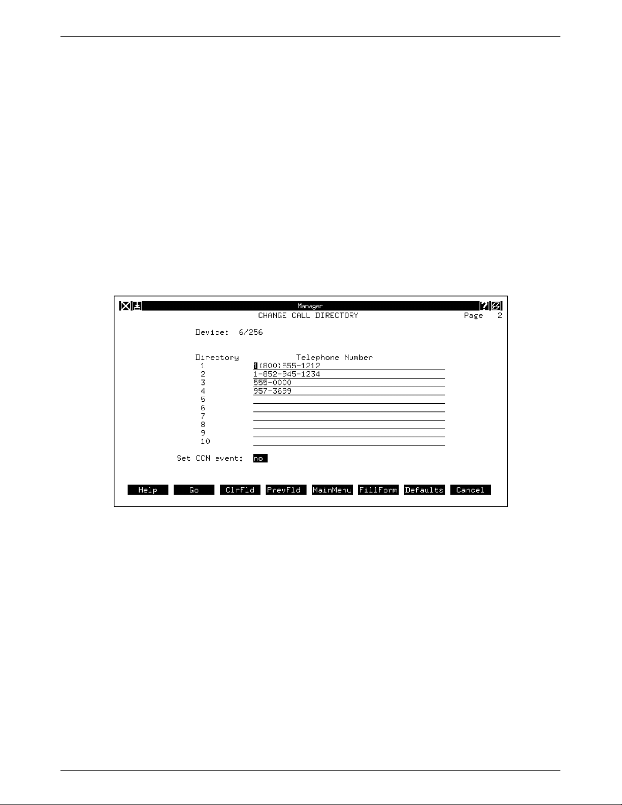
2-11 Change Call Directory Input Form for a
3800 Series Modem/3600 Series DBM, Page2 2-40. . . . . . . . . . . . . . . . . . . . . . . . . . .
2-12 Change Call Directory Input Form for a
3400/4400 Series APL Modem with DBM, Page 2 2-42. . . . . . . . . . . . . . . . . . . . . . .
2-13 Change Exception Reporting Thresholds Input Form, Page 1 2-49. . . . . . . . . . . . . . . . .
2-14 Change [Device] Poll List Input Form, Page 2 2-61. . . . . . . . . . . . . . . . . . . . . . . . . . . . .
2-15 Change [Device] Poll List Results Form 2-62. . . . . . . . . . . . . . . . . . . . . . . . . . . . . . . . . .
2-16 Change Protocol Mode Results Form 2-70. . . . . . . . . . . . . . . . . . . . . . . . . . . . . . . . . . . .
2-17 Change Thresholds Input Form, Page 2 2-75. . . . . . . . . . . . . . . . . . . . . . . . . . . . . . . . . . .
2-18 Circuit Loss Inbound Results Form 2-79. . . . . . . . . . . . . . . . . . . . . . . . . . . . . . . . . . . . . .
2-19 Circuit Loss Outbound Results Form 2-81. . . . . . . . . . . . . . . . . . . . . . . . . . . . . . . . . . . .
2-20 Circuit Quality Results Form for COMSPHERE 3800 Series Modems 2-83. . . . . . . . . .
2-21 Circuit Quality Results Form for 3600 Series DSUs 2-84. . . . . . . . . . . . . . . . . . . . . . . . .
2-22 Circuit Quality Results Form for 3900 Series Modems 2-85. . . . . . . . . . . . . . . . . . . . . . .
2-23 Configuration Change Notification Results Form 2-90. . . . . . . . . . . . . . . . . . . . . . . . . . .
2-24 Daily Historical Utilization Results Form, Page 2 2-96. . . . . . . . . . . . . . . . . . . . . . . . . . .
2-25 Daily Historical Utilization Results Form, Page 3 2-96. . . . . . . . . . . . . . . . . . . . . . . . . . .
2-26 Device Health and Status Results Form for Single Devices 2-98. . . . . . . . . . . . . . . . . . .
2-27 Device Health and Status Results Form for Subnetwork Devices 2-100. . . . . . . . . . . . . . .
2-28 Dial Command Input Form 2-105. . . . . . . . . . . . . . . . . . . . . . . . . . . . . . . . . . . . . . . . . . . .
2-29 Digital T est Input Form 2-111. . . . . . . . . . . . . . . . . . . . . . . . . . . . . . . . . . . . . . . . . . . . . . .
2-30 Digital T est Results Form for DATAPHONE II APL Modems 2-112. . . . . . . . . . . . . . . . .
2-31 Digital T est Results Form for 3400/4400 Series APL Modems 2-113. . . . . . . . . . . . . . . .
2-32 Digital T est Results Form for 3600 Series DSUs/DBMs 2-114. . . . . . . . . . . . . . . . . . . . . .
2-33 Display Alert Information Results Form 2-120. . . . . . . . . . . . . . . . . . . . . . . . . . . . . . . . . .
iii6800-A2-GB31-20 January 1997
Page 6

COMSPHERE 6800 Series Network Management System
Figure Page
2-34 Display Call Directory Results Form for a 3800 Series Modem 2-123. . . . . . . . . . . . . . . .
2-35 Display Call Directory Results Form for 3400/4400 Series Modem with a DBM 2-124. .
2-36 Display Exception Reporting Thresholds Results Form, Page 1 2-127. . . . . . . . . . . . . . . .
2-37 Display Exception Reporting Thresholds Results Form, Page 2 2-128. . . . . . . . . . . . . . . .
2-38 Display External Leads States Results Form 2-130. . . . . . . . . . . . . . . . . . . . . . . . . . . . . . .
2-39 Display Line Designator Results Form 2-132. . . . . . . . . . . . . . . . . . . . . . . . . . . . . . . . . . .
2-40 Display [Device] Poll List Results Form 2-135. . . . . . . . . . . . . . . . . . . . . . . . . . . . . . . . . .
2-41 Display Port Options Results Form, Page 1 2-137. . . . . . . . . . . . . . . . . . . . . . . . . . . . . . . .
2-42 Display Port Options Results Form, Page 2 2-137. . . . . . . . . . . . . . . . . . . . . . . . . . . . . . . .
2-43 Display Port Speed(s) Results Form for 19.2 kbps Modem, Page 1 2-139. . . . . . . . . . . . .
2-44 Display T elephone Number Results Form for 3400/4400 Series Modems 2-141. . . . . . . .
2-45 Download Device Firmware Input Form, Page 1 2-145. . . . . . . . . . . . . . . . . . . . . . . . . . .
2-46 EIA Status Results Form for COMSPHERE 3800 Series Modems, Page 1 2-151. . . . . . .
2-47 EIA Status Results Form for COMSPHERE 3800 Series Modems, Page 2 2-151. . . . . . .
2-48 EIA Status Results Form for COMSPHERE 3900 Series Modems, Page 1 2-154. . . . . . .
2-49 EIA Status Results Form for COMSPHERE 3900 Series Modems, Page 2 2-154. . . . . . .
2-50 End-to-End T est Input Form 2-157. . . . . . . . . . . . . . . . . . . . . . . . . . . . . . . . . . . . . . . . . . .
2-51 End-to-End Test Results Form 2-158. . . . . . . . . . . . . . . . . . . . . . . . . . . . . . . . . . . . . . . . . .
2-52 Exception Reports Input Form 2-160. . . . . . . . . . . . . . . . . . . . . . . . . . . . . . . . . . . . . . . . . .
2-53 Exception Reports Results Form, Page 1 2-162. . . . . . . . . . . . . . . . . . . . . . . . . . . . . . . . . .
2-54 Exception Reports Results Form, Page 2 2-164. . . . . . . . . . . . . . . . . . . . . . . . . . . . . . . . . .
2-55 Identity Results Form for 3400/4400 Series Modems, Page 1 2-166. . . . . . . . . . . . . . . . .
2-56 Identity Results Form for 3600 Series DSUs with
DDS-SC Firmware and CISC Chip, Page 1 2-168. . . . . . . . . . . . . . . . . . . . . . . . . . . . .
2-57 Identity Results Form for COMSPHERE 3800 DDD 2-170. . . . . . . . . . . . . . . . . . . . . . . .
2-58 Identity Results Form for COMSPHERE 3900 APL 2-172. . . . . . . . . . . . . . . . . . . . . . . .
2-59 List Directory Results Form 2-175. . . . . . . . . . . . . . . . . . . . . . . . . . . . . . . . . . . . . . . . . . . .
2-60 Modem Bit Error Rate Test Results Form for Display/Reset Bert Counters 2-184. . . . . . .
2-61 Receive Signal Spectrum Results Form (Display) 2-190. . . . . . . . . . . . . . . . . . . . . . . . . . .
2-62 Signal Profile Results Form 2-200. . . . . . . . . . . . . . . . . . . . . . . . . . . . . . . . . . . . . . . . . . . .
2-63 Training Time Results Form 2-206. . . . . . . . . . . . . . . . . . . . . . . . . . . . . . . . . . . . . . . . . . .
2-64 Trending Reports Initial Input Form 2-211. . . . . . . . . . . . . . . . . . . . . . . . . . . . . . . . . . . . .
2-65 Trending Reports Results Form – Tabular, Page 2 2-213. . . . . . . . . . . . . . . . . . . . . . . . . .
2-66 Trending Reports Results Form – Statistics, Page 3 2-214. . . . . . . . . . . . . . . . . . . . . . . . .
iv January 1997 6800-A2-GB31-20
Page 7

Table of Contents
List of Tables
Tables Page
2-1 Signal Profile for 2024A Modem 2-50. . . . . . . . . . . . . . . . . . . . . . . . . . . . . . . . . . . . . . .
2-2 Signal Profile for 2048A and C Modems 2-51. . . . . . . . . . . . . . . . . . . . . . . . . . . . . . . . .
2-3 Signal Profile for 2096A and C Modems 2-51. . . . . . . . . . . . . . . . . . . . . . . . . . . . . . . . .
2-4 Signal Profile for 2024A Modem 2-201. . . . . . . . . . . . . . . . . . . . . . . . . . . . . . . . . . . . . . .
2-5 Signal Profile for 2048A and C Modems 2-201. . . . . . . . . . . . . . . . . . . . . . . . . . . . . . . . .
2-6 Signal Profile for 2096A and C Modems 2-202. . . . . . . . . . . . . . . . . . . . . . . . . . . . . . . . .
v6800-A2-GB31-20 January 1997
Page 8

Preface
Objectives and Reader Assumptions
This manual provides a description of the device commands that can be used only with
COMSPHERE 3400/4400 Series modems, COMSPHERE 3800 Series modems, COMSPHERE
3900 Series modems, DATAPHONE II Analog Private Line (APL) and DATAPHONE II Direct
Distance Dial (DDD) modems, 3600 Series DSUs, and DATAPHONE II Data Service Units
(DSUs) managed and monitored by the COMSPHERE 6800 Series Network Management System
(NMS).
It is assumed that you are familiar with the operation of these devices, have read the
COMSPHERE 6800 Series Network Management System User’s/System Administrator’s Guide
and are familiar with the use of the COMSPHERE 6800 Series Network Management System.
Related Documents
Contact your sales representative for additional product documentation.
3420-A2-GB41 COMSPHERE 3400/4400 Series Model 2 Network Diagnostic Modems,
Medium-Speed Supplement
3420-A2-GB43 COMSPHERE 3400/4400 Series Model 2 Network Diagnostic Modems,
High-Speed Point-to-Point Supplement
3420-A2-GB45 COMSPHERE 3400/4400 Series Model 2 Network Diagnostic Modems,
Trellis Multipoint Supplement
3420-A2-GL12 COMSPHERE 3400/4400 Series Model 2 Network Diagnostic Modems
Reference Card
3420-A2-GN82 COMSPHERE 3400/4400 Series Model 2 Network Diagnostic Modems,
Installation and Operation Manual
3610-A2-GB91 COMSPHERE 3600 Series Data Service Units, Models 3610 and 3611,
Operator’s Guide
3810-A2-GB91 COMSPHERE 3800 Series Modems, Models 3810, 3811, and 3820,
User’s Guide
3830-A2-GB91 COMSPHERE 3800 Series Modems, Model 3830, User’s Guide
viiJanuary 19976800-A2-GB31-20
Page 9

COMSPHERE 6800 Series Network Management System
3910-A2-GN32 COMSPHERE 3900 Series Modems, Models 3910 and 3911
6500-A2-GA21 ANALYSIS 6510 Automated Network Management System Reference
6800-A2-GB30 COMSPHERE 6800 Series Network Management System Core
6800-A2-GB32 COMSPHERE 6800 Series Network Management System Multiplexer
6800-A2-GE26 COMSPHERE 6800 Series Network Management System User’s/ System
999-100-192IS DATAPHONE II 2048T Modem User’s Manual
999-100-193IS DATAPHONE II 2024T Modem User’s Manual
Point-to-Point/Multipoint, Installation and Operation Manual
Manual
Command Reference Manual
Command Reference Manual
Administrator’s Guide
999-100-194IS DATAPHONE II 2096T Modem User’s Manual
999-100-196IS DATAPHONE II 2600-Series Data Service Units User’s Manual
999-100-213IS DATAPHONE II Private Line Modems 2024, 2048, and 2096 Types
User’s Manual
999-100-227 DATAPHONE II 745 ACCULINK Multiplexer User’s Manual
999-100-230IS DATAPHONE II 2224E Full-Duplex Modem User’s Manual
999-100-231IS DATAPHONE II Series 700 STAT MUX User’s Manual
999-100-234IS DATAPHONE II Series 700 NETWORKER User’s Manual
999-100-237IS DATAPHONE II Series 700-724/735 T-MUX User’s Manual
999-100-250IS DATAPHONE II 2144A Modem User’s Manual
999-100-252IS DATAPHONE II 2248 Stand-Alone Modem User’s Manual
999-100-287 DATAPHONE II 2296A Modem User’s Manual
999-100-289IS DATAPHONE II 740/741 ACCULINK Multiplexer User’s Manual
999-100-296 DATAPHONE II 2192A Modem User’s Manual
viii January 1997 6800-A2-GB31-20
Page 10

1Introduction
Overview 1-1. . . . . . . . . . . . . . . . . . . . . . . . . . . . . . . . . . . . . . . . . . . . . . . . . . . .
6800 Series NMS Communications Products 1-2. . . . . . . . . . . . . . . . . . . . . .
NMS-Supported APL Modems 1-2. . . . . . . . . . . . . . . . . . . . . . . . . . . . . .
NMS-Supported Direct Distance Dialing (DDD) Modems 1-2. . . . . . . . .
NMS-Supported Data Service Units (DSUs) 1-3. . . . . . . . . . . . . . . . . . . .
Paradyne APL Modems and DSUs
(via ANALYSIS Gateway) 1-3. . . . . . . . . . . . . . . . . . . . . . . . . . . . . . . .
Naming Conventions 1-3. . . . . . . . . . . . . . . . . . . . . . . . . . . . . . . . . . . . . . . . .
Device Addressing. 1-4. . . . . . . . . . . . . . . . . . . . . . . . . . . . . . . . . . . . . . . . . .
Command Support – Customer Configurations 1-4. . . . . . . . . . . . . . . . . . . .
Command Access 1-4. . . . . . . . . . . . . . . . . . . . . . . . . . . . . . . . . . . . . . . . . . .
Shortcut for Command Access 1-5. . . . . . . . . . . . . . . . . . . . . . . . . . . . . . .
Wildcard Characters 1-5. . . . . . . . . . . . . . . . . . . . . . . . . . . . . . . . . . . . . . .
Multiple Entries 1-5. . . . . . . . . . . . . . . . . . . . . . . . . . . . . . . . . . . . . . . . . .
Format for Documenting Commands in this Manual 1-6. . . . . . . . . . . . . . . . . . .
Command Input Forms 1-8. . . . . . . . . . . . . . . . . . . . . . . . . . . . . . . . . . . . . . . . . .
Required Fields 1-8. . . . . . . . . . . . . . . . . . . . . . . . . . . . . . . . . . . . . . . . . . . . .
Optional Fields 1-8. . . . . . . . . . . . . . . . . . . . . . . . . . . . . . . . . . . . . . . . . . . . .
Display-only Fields 1-9. . . . . . . . . . . . . . . . . . . . . . . . . . . . . . . . . . . . . . . . . .
Carried-over Fields 1-9. . . . . . . . . . . . . . . . . . . . . . . . . . . . . . . . . . . . . . . . . .
Common Fields on Input Forms – Destination for results and
Schedule execution 1-9. . . . . . . . . . . . . . . . . . . . . . . . . . . . . . . . . . . . . . . .
Results Forms 1-12. . . . . . . . . . . . . . . . . . . . . . . . . . . . . . . . . . . . . . . . . . . . . .
Help 1-13. . . . . . . . . . . . . . . . . . . . . . . . . . . . . . . . . . . . . . . . . . . . . . . . . . . . . . . .
In Menu 1-13. . . . . . . . . . . . . . . . . . . . . . . . . . . . . . . . . . . . . . . . . . . . . . . . . . .
In Forms 1-13. . . . . . . . . . . . . . . . . . . . . . . . . . . . . . . . . . . . . . . . . . . . . . . . . .
For Screen Input Fields 1-14. . . . . . . . . . . . . . . . . . . . . . . . . . . . . . . . . . . . . . .
1
Overview
This manual describes the communications product commands that are used to manage various
modem types and Data Service Units (DSUs).
This chapter provides information on using the 6800 Series Network Management System
(referred to as NMS in this document) and accessing the modem/DSU commands. It also provides
a description of the command format used in this manual to document each command. It includes
instructions on entering abbreviated versions of options and wildcard characters when specifying
command execution parameters. The common fields (Destination for results and Schedule
execution) in the command input forms are defined in detail to eliminate the repetition of this
information for each command.
The modem/DSU commands can be used with the COMSPHERE and DATAPHONE II data
products. You access these commands under Network Control in the Manager task. The Trending
Reports and call statistics reports commands can also be accessed from the Performance Reports
task. Functionally, the commands under the Performance Reports task operate the same as those
commands of the same name under Network Control in the Manager task.
1-16800-A2-GB31-20 January 1997
Page 11

COMSPHERE 6800 Series Network Management System
It is assumed that you are already familiar with the screen functions offered with both the
full-feature 6800 Series NMS workstation and the basic-feature 6800 Series NMS workstation. If
you are not familiar with the screen functions provided by the workstations, refer to Chapter 2,
Getting Started, in the COMSPHERE 6800 Series Network Management System User’s/System
Administrator’s Guide for this information.
6800 Series NMS Communications Products
This document describes tests and commands for the following communications products:
NMS-Supported APL Modems
NMS supports the following APL modems:
COMSPHERE 3400/4400 Series Modems
These modems consist of 4.8 kbps point-to-point and multipoint modems, 14.4/9.6 kbps
multipoint modems, and 19.2/14.4 kbps point-to-point modems. These modems are
capable of full-duplex, synchronous data transmission over analog private lines (APL).
The 3400/4400 Series modems incorporate the VLSI (Very Large Scale Integration)
design with new generation architecture referred as a Universal Signal Processor (USP).
The USP architecture provides unparalleled processing power for superior online
performance, network control, and future product enhancements.
DATAPHONE II Analog Private Line (APL) Modems
These modems are capable of full-duplex, synchronous data transmission over analog
private line channels at speeds up to 19.2 kbps. APL modems can be used as control or
tributary modems in a point-to-point, multipoint, or secondary diagnostic channel using
the low end of the analog private line’s bandwidth. Through this secondary channel, the
6800 Series NMS is able to manage and monitor the modems.
COMSPHERE 3900 Series Modems
The COMSPHERE 3900 Series modems are standalone or carrier-mounted devices which
operate on either 2-wire PSTN or APL facilities in either synchronous or asynchronous
mode. These modes are available for both point-to-point and multipoint configurations.
NMS-Supported Direct Distance Dialing (DDD) Modems
NMS supports the following DDD modems:
COMSPHERE 3800 Series Direct Distance Dialing (DDD) (or Software-defined) Modems
The COMSPHERE 3800 Series DDD software-defined modem is a standalone or
carrier-mounted device. There are five models available (3810-A1-001, 3811-B1-001,
3820-A1-001, 3830-A1-001, and 3830-a1-001.) Models 3810-A1-001 and 3811-B1-001
conform to the following rule: the dial/leased models support dial, 2-wire leased, or
4-wire leased communications. They also support automatic backup of the leased line.
Model 3820-A1-001 conforms to the following rule: the dial modem supports dial or
2-wire leased communications; automatic backup of the leased line is not supported.
1-2 January 1997 6800-A2-GB31-20
Page 12

DATAPHONE II Direct Distance Dialing (DDD) Modems
These modems are capable of full-duplex synchronous or asynchronous data transmission
over the switched telecommunications network at speeds up to 9.6 kbps. The DDD
modems collocated with the 6800 Series NMS have a control channel interface that
allows monitoring by the 6800 Series NMS.
These modems interface with the 6800 Series NMS through the Shared Diagnostic Units
(SDUs). Each SDU oversees up to eight switched network modems and are fully
addressable by NMS.
NMS-Supported Data Service Units (DSUs)
NMS supports the following DSU products:
DATAPHONE II 2600 and 2700 DSUs
These DSUs are designed for multipoint and point-to-point applications. The 2600 Series
DSUs provide digital, full-duplex network data transmission over the DATAPHONE
Digital Service (DDS) and the ACCUNET Switched 56 Service and do not have
diagnostic capabilities. The 2700 Series DSUs, with a secondary channel capability,
provide digital, full-duplex synchronous data transmission over DDS facilities plus full,
nondisruptive diagnostic capabilities.
1Introduction
COMSPHERE 3600 Series Data Service Units (DSUs)
These DSUs are capable of multispeed operations on the DATAPHONE Digital Service
network or equivalent Digital Data Services network, and can operate as local area
datasets (limited-distance modems). An optional integrated V.32 dial backup module
(DBM) enables backup through the public switched telephone network in case of failure
of the digital connection. DSU interface to the 6800 Series NMS can be via either control
channel connection when directly connected to the 6800 Series NMS, or via diagnostic
channel connection when remotely connected to the 6800 Series NMS.
Paradyne APL Modems and DSUs (via ANALYSIS Gateway)
These modems consist of the MPX, LSI24, and the 3400 Series high-speed DMC protocol APL
modems. These modems perform at speeds ranging from 1.2 kbps to 19.2 kbps. These speeds are
accomplished by using a variety of CCITT Paradyne proprietary and Forward Error Correcting
(FEC) modulation schemes as appropriate for the specific model chosen. The modems can be
controlled by NMS using the cut-through feature and ANALYSIS Gateway, by ANALYSIS NMS,
or independently through the modem’s Diagnostic Control Panel (DCP). The DCP allows the
operator of a modem which is optioned as a control to configure, monitor, and test both the control
and tributary modems in the network.
Naming Conventions
NMS naming conventions enable you to assign a name to a device and to assign a network or
circuit name to a group of logically related devices, such as those devices sharing a common
customer, location, or application. You can then reference or test a group of devices, a network, or
a circuit by entering a single name. Refer to Appendix E of the COMSPHERE 6800 Series
Network Management System User’s/System Administrator’s Guide for a description of the device
naming method accepted by NMS.
1-36800-A2-GB31-20 January 1997
Page 13

COMSPHERE 6800 Series Network Management System
Device Addressing
Device addressing allows the 6800 Series NMS to communicate with the devices in the network.
Refer to Appendix D of the COMSPHERE 6800 Series Network Management System
User’s/System Administrator’s Guide for a description of the device addressing method accepted
by NMS.
Command Support – Customer Configurations
This manual addresses all NMS modem/DSU commands although some commands may not
pertain to your specific configuration. If you attempt to execute a command that is not supported
by your configuration, either the NMS will not act on the command or if the command is sent, the
network will respond with an appropriate message. For example, if you attempt to send the Make
Busy (mb) command to 3600 Series DSUs in your system configuration, the following message is
displayed:
Test not sent. Test device mismatch.
Command Access
When you log on to the 6800 Series NMS, the 6800 Series NMS Tasks menu displays
(Figure 1-1).
To issue a modem/DSU command, select the Manager task. Then, select Network Control. Once
you have accessed the Network Control task, you can type any valid modem/DSU command
abbreviation in the enter selection field of any submenu within Network Control to access the
command; or you can select a modem/DSU command from any of the Network Control submenus
that list the commands with their assigned abbreviations. Once the selection is made, you can
select Go (F2) to request the command’s input form. For more information on selecting commands
depending on basic-feature or full-feature workstations, refer to the COMSPHERE 6800 Series
Network Management System User’s/System Administrator’s Guide. All modem/DSU commands
display one or more input forms prior to command execution, and display one or more results
forms after the command has executed.
1-4 January 1997 6800-A2-GB31-20
Page 14

1Introduction
Shortcut for Command Access
You can type any command valid for a task window in the enter selection field of any submenu
within that task windows and select Go (F2).
Wildcard Characters
In device address fields, you can enter an asterisk (*) to specify any character string. For command
execution, when specifying a group of devices whose names begin with a common root, a wildcard
character (*) can be entered directly following the common root. For example, to test all devices
with device names beginning with ny, enter ny* in the Device(s) field on the input form. For more
information on wildcard characters, refer to Appendix E of the COMSPHERE 6800 Series
Network Management System User’s/System Administrator’s Guide.
Multiple Entries
Multiple entries are permitted in some fields. You must separate each entry with either a comma or
a space. These fields are identified in the manual.
Figure 1-1. 6800 Series NMS Tasks Menu
1-56800-A2-GB31-20 January 1997
Page 15

COMSPHERE 6800 Series Network Management System
Format for Documenting Commands in this Manual
Each command documented in this manual begins on a new page. If the command is disruptive
(i.e., interferes with the primary data channel), the word Disruptive is indicated immediately below
the command name.
The format for documenting each command is the same. The function of the command is briefly
summarized. Then the information fields are listed, as follows:
Access Level
Identifies the user group that is allowed to access the command. NMS commands are
associated with at least one of four default user groups, or access levels. These levels are,
in order of increasing command permission:
• Help Desk
• Data T echnician
• Manager
• System Administrator
In addition to the four default user groups, the NMS System
Administrator can create up to 26 other user groups for each
command in this manual. It is the responsibility of the NMS System
Administrator to inform all the users of their system.
To execute a command, users must have the appropriate functional access level set in their
user profile. Any command associated with a particular user group can be executed by
any user that has equal or greater command permission. Therefore, it is assumed that the
System Administrator has access to all commands. If a user does not have permission to a
command, that command is not displayed in the user’s menus. If the user attempts to
invoke the command in the enter selection field, a message is returned indicating that
permission is denied. The default access levels for all commands are listed in Appendix B
in the COMSPHERE 6800 Series Network Management System User’s/System
Administrator’s Guide.
Abbreviation
Identifies the abbreviation of the command as it appears in the command submenus. If the
command submenus are bypassed by typing the command in the enter selection field, the
command abbreviation must be entered exactly as shown.
An abbreviation is provided for each command. For some commands, an alternate
command abbreviation from earlier 6800 Series NMS releases is also recognized. For
such commands, these alternate abbreviations are also listed.
NOTE
1-6 January 1997 6800-A2-GB31-20
Page 16

Restrictions
Identifies any limitations associated with the execution of the command, or any additional
information concerning command execution that you may need for successful execution
of the command. If no restrictions apply to the command, None is indicated in this field.
Routine
Indicates whether or not (yes/no) a command can be placed in a routine. A routine is a set
of up to 25 commands that can be grouped together and executed sequentially by
specifying the routine name on the enter selection field. The determination of whether or
not a command can be placed in a routine depends, in part, on the task window from
which the command is accessed.
Schedule
Identifies whether or not (yes/no) a command can be scheduled for later or repeated
execution. The determination of whether or not a command can be scheduled depends, in
part, on the task window from which the command is accessed. Refer to the discussion on
Schedule execution under the section Common Fields on Input Forms – Destination for
results and Schedule execution in this chapter for additional information on scheduling
parameters.
1Introduction
Unless specifically noted, any command that can be placed in a routine can be scheduled.
Related Commands
Lists other modem/DSU commands that relate to the function executed by this command.
1-76800-A2-GB31-20 January 1997
Page 17
COMSPHERE 6800 Series Network Management System
Command Input Forms
Every modem/DSU command uses one or more input form pages. The appropriate input form
pages display when you invoke a command, enabling you to identify the specific device for which
the command is to be executed and, as applicable, to enter parameters required for execution of the
command. When you specify multiple devices on the initial input form, a second input form
displays with blank fields. This acts as a template allowing you to enter values for all devices
specified.
On most of the input forms that list valid entry options for a field in a pop-up menu, you are able to
abbreviate your entry of the option by typing the first or first few characters of the word to
uniquely identify that word to the system. For example, in the Destination for results field, the
valid entry options are crt, remote, printer, queue. You need to enter only the first letter of each
word (c, r, p, q, respectively) to uniquely identify that option word from the other listed options.
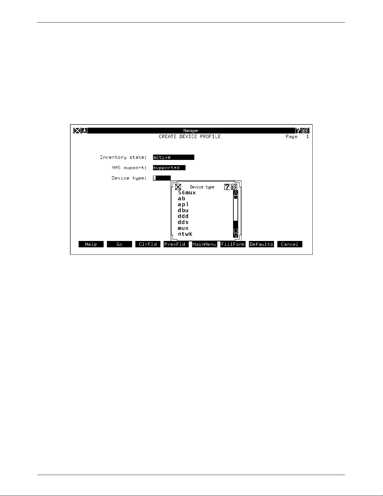
Figure 1-2 is an example of an input form.
Figure 1-2. Example Input Form
Required Fields
Certain fields on the input form require that you input the data requested before NMS allows you
to execute the command. Required fields appear on the input form in a solid box.
Optional Fields
Some fields do not require you to input data before continuing with the command, either because
this data is not needed by NMS, the data is supplied by the devices via NMS, or (in the case of
sorting selection fields) this field can be ignored in the search. Optional fields appear on the input
form as underlined.
1-8 January 1997 6800-A2-GB31-20
Page 18

Display-only Fields
Certain fields display data, but do not allow you to enter new data or change the data displayed.
Display-only fields appear on the input forms without boxes or underlines.
Carried-over Fields
Some fields display information provided by the user on a previous form of the current command.
Carried-over fields may be display-only, or in some cases, may allow user input.
Common Fields on Input Forms – Destination for results and Schedule execution
Destination for results
Use this field to specify where NMS should send the results from the command
execution. Valid options are crt, remote, printer, lp, and queue. Multiple destinations can
be specified.
1Introduction
crt (default)
This selection causes the command results to display on your workstation screen.
When you specify the destination as crt, the command must be executed
immediately. It cannot be scheduled for a later time.
NOTE
When you specify crt, NMS does not allow any other command to
be accessed from the current window until execution of the current
command has completed. Certain commands, e.g., tests that take
time to execute, or reports that include large volumes of data, can
take several minutes to complete. In these instances it is
recommended that you send the results of the command to a queue
or to a printer. The command will execute in the background,
allowing you to access and execute other commands at the same
time.
remote
This selection sends the results of the command to a remotely located printer. If
you specify remote, a telephone number prompt displays on the screen allowing
you to specify the telephone number of the remote printer. If an ACU phone
number has been included in your user profile (an optional field), this phone
number becomes the default number.
lp
Sends results to a remote line printer. You are prompted for the name of the
remote printer in a field that appears below the destination field.
1-96800-A2-GB31-20 January 1997
Page 19

COMSPHERE 6800 Series Network Management System
printer
This selection sends the results of the command to the local system printer
assigned in your user profile.
queue
This selection sends the results of the command to one of your own results
queues. Command results may go to one of three results queues, depending on
the task window from which the command was executed.
Schedule execution
This option enables you to direct the system to execute commands and routines
automatically at selected times or repeatedly at regular intervals. Valid options are now,
delayed, weekly, and monthly.
now (default)
Causes the command to be executed immediately. If you enter crt in the
Destination for results field, you must enter now in the Schedule execution
field.
delayed
Causes the command to be executed at a future time. When you enter delayed in
the Schedule execution field, the system displays the following fields:
Date(s)
Enter the date(s) on which the command will execute. You may enter as
many dates as will fit in the field. Separate all dates with commas
or spaces. Valid entries are today, today+nn, last, mm/dd/yy, mm/dd,
dd.
Where: today = Execute today.
today+nn = Execute nn number of days from today.
last = Execute on the last day of the month.
mm/dd/yy = Execute on the specified month, day
and year.
mm/dd = Execute on the specified month and
day; the year defaults to the current
year.
dd = Execute on the specified day; the month
and year default to the current month
and year.
1-10 January 1997 6800-A2-GB31-20
Page 20

weekly
1Introduction
Time(s)
Enter the time(s) at which the command will execute.
Valid entries are hh:mm, hh:mmam or pm, hh-hh:mm, and all:mm
Where: hh:mm = Execute at the 24-hour time specified.
hh:mmam
or
hh:mmpm = Execute at the 12-hour time specified
with an am or pm designation.
hh-hh:mm = Execute every hour within the time
range specified, at the specified minute.
all:mm = Execute every hour at the specified
minute.
Causes the command to execute on a weekly basis. When you enter weekly in the
Schedule execution field, the system displays the following fields:
Day(s) of the week
Enter the day(s) of the week when the command is to execute. Valid entries are
as follows:
• The days of the week in abbreviated form, e.g., sun, mon, tue, wed,
• A range of days separated by a dash, e.g., sun-thu.
• The keyword all for all days of the week.
Time(s)
Enter the time(s) the command is to execute for each day specified. For time(s)
entry parameters, refer to the Time(s) field explanation for delayed command
execution.
Last date
Enter the stop date for command execution. If you leave this field blank the
command will execute indefinitely on a weekly basis. The last date must occur
after the first scheduled date.
For data format, refer to the Date(s) field explanation for delayed command
execution.
thu, fri, sat. Multiple entries are allowed separated by commas or
spaces.
1-116800-A2-GB31-20 January 1997
Page 21

COMSPHERE 6800 Series Network Management System
monthly
Causes the command to execute on a monthly basis. When you enter monthly into the
Schedule execution field, the system displays the following fields:
Day(s) of the month
Enter the day(s) of the month when this command is to execute. Valid entries are
as follows:
• Multiple days. The numbers must be separated by commas or spaces,
• A range of days, e.g., 8-15.
• The keyword last to execute the command on the last day of the current
• The keyword all to execute the command each day of the current
Time(s)
e.g., 1,4,7,10.
month.
month.
Results Forms
Enter the time(s) the command is to execute for each day specified. For time(s)
format, refer to the Time(s) field explanation for delayed command execution.
Last date
Enter the stop date for execution of the command. If you leave this field blank,
the command will execute on a monthly basis indefinitely. The last date must
occur after the first scheduled date.
For date entry parameters refer to the Date(s) field explanation for delayed
command execution.
Each modem/DSU command is associated with one or more results forms. Depending on the
command issued, the results form(s) can display a success or failure message for command
execution, reflect the changes made for a device as a result of the command execution, and display
detailed information (e.g., health and status statistics) for the specified device(s). A results form
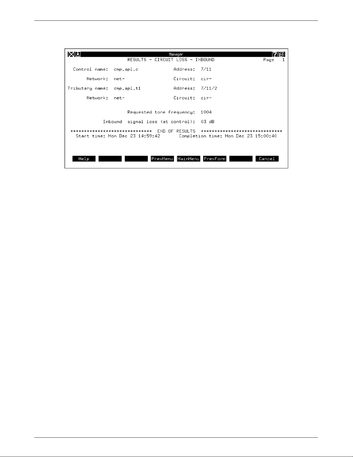
trailer message indicates start and stop times for command execution. Figure 1-3 shows an
example of a results form for the Circuit Loss Inbound (cli) command, which is used to measure
the inbound circuit loss to a specified COMSPHERE APL modem or DATAPHONE II APL device
from an associated tributary. The results form for this command reflects the tone frequency
specified and the decibel (dB) level of the inbound signal loss for the device(s) specified.
1-12 January 1997 6800-A2-GB31-20
Page 22
1Introduction
Help
In Menus
In Forms
Figure 1-3. Sample Results – Form Circuit Loss Inbound (cli) Command
NMS provides several help features to assist you in command input and execution. Help is
available on all screens by selecting Help(F1). This function key displays a pop-up Help screen,
explaining the function keys and how to invoke the Help feature. On the 6800 Series NMS T ask
menu, it defines the T ask menu screen functions: Tasks, Windows, Logoff, Refresh, and NewMail.
Help features within the tasks can be accessed as follows:
From the full-feature workstation, you can obtain general help for a task from within any menu by
selecting the ? icon on the task window title bar. From a basic-feature workstation, you can obtain
general help for a task by typing the key sequence ESC ?.
All forms (both input and results) have associated form help text. Form help is accessed from a
full-feature workstation by selecting the ? icon on the task window title bar. From a basic-feature
workstation, type the key sequence ESC ?.
Form help includes a general description of the form currently displayed. The form help text for
input forms also includes general descriptions of how to enter input, how to access field help, and
the types of field help available (selectable menu vs. field help text).
1-136800-A2-GB31-20 January 1997
Page 23
COMSPHERE 6800 Series Network Management System
For Screen Input Fields
Within forms, Field Help menus or text messages are accessed by selecting field labels with the
mouse from a full-feature workstation (or typing ?). From a basic-feature workstation, type a ? in
the input field. The cursor must be positioned on the field for which help is needed. For tabular
fields, the column label should be selected. Refer to Figure 1-4 for an example of selecting fields
listed in tabular form.
Figure 1-4. Selecting Fields Listed in Tabular Form
Each field that accepts user input has associated field help. Depending on the type of field (either
fixed parameter or variable parameter [i.e., a value within a range of values]), field help is either a
selectable menu of valid field entries, or a text message which describes the valid input format(s)
or entries.
1-14 January 1997 6800-A2-GB31-20
Page 24

2Modem/DSU Commands
Overview 2-2. . . . . . . . . . . . . . . . . . . . . . . . . . . . . . . . . . . . . . . . . . . . . . . . . . . .
Abort (abort) 2-3. . . . . . . . . . . . . . . . . . . . . . . . . . . . . . . . . . . . . . . . . . . . . . . . .
Acquire [Device] Poll List (acpl) 2-5. . . . . . . . . . . . . . . . . . . . . . . . . . . . . . . . . .
Automatic Network Test (ant) 2-7. . . . . . . . . . . . . . . . . . . . . . . . . . . . . . . . . . . .
Calibrate Tributary Transmitter (ctt) 2-9. . . . . . . . . . . . . . . . . . . . . . . . . . . . . . . .
Call Detail Display (cded) 2-11. . . . . . . . . . . . . . . . . . . . . . . . . . . . . . . . . . . . . . .
Call Duration Distribution (cdud) 2-15. . . . . . . . . . . . . . . . . . . . . . . . . . . . . . . . . .
Call Fault Criteria (cfc) 2-20. . . . . . . . . . . . . . . . . . . . . . . . . . . . . . . . . . . . . . . . . .
Call Fault Read (cfr) 2-24. . . . . . . . . . . . . . . . . . . . . . . . . . . . . . . . . . . . . . . . . . . .
Call Message (cm) 2-27. . . . . . . . . . . . . . . . . . . . . . . . . . . . . . . . . . . . . . . . . . . . .
Call Occurrence Distribution (cod) 2-29. . . . . . . . . . . . . . . . . . . . . . . . . . . . . . . .
Call Test (ct) 2-32. . . . . . . . . . . . . . . . . . . . . . . . . . . . . . . . . . . . . . . . . . . . . . . . . .
Change Address (cha) 2-34. . . . . . . . . . . . . . . . . . . . . . . . . . . . . . . . . . . . . . . . . .
Change Call Directory (chcd) 2-39. . . . . . . . . . . . . . . . . . . . . . . . . . . . . . . . . . . . .
Change Canned Message (chcm) 2-44. . . . . . . . . . . . . . . . . . . . . . . . . . . . . . . . . .
Change Directory (chd) 2-46. . . . . . . . . . . . . . . . . . . . . . . . . . . . . . . . . . . . . . . . .
Change Exception Reporting Thresholds (chert) 2-48. . . . . . . . . . . . . . . . . . . . . .
Change External Leads States (chels) 2-53. . . . . . . . . . . . . . . . . . . . . . . . . . . . . . .
Change Line Designator (chld) 2-55. . . . . . . . . . . . . . . . . . . . . . . . . . . . . . . . . . . .
Change Multiplexer (chm) 2-56. . . . . . . . . . . . . . . . . . . . . . . . . . . . . . . . . . . . . . .
Change Options (cho) 2-58. . . . . . . . . . . . . . . . . . . . . . . . . . . . . . . . . . . . . . . . . .
Change [Device] Poll List (chpl) 2-60. . . . . . . . . . . . . . . . . . . . . . . . . . . . . . . . . .
Change Port Options (chpo) 2-63. . . . . . . . . . . . . . . . . . . . . . . . . . . . . . . . . . . . .
Change Port Speed(s) (chpsp) 2-65. . . . . . . . . . . . . . . . . . . . . . . . . . . . . . . . . . . .
Change Protocol Mode (chpm) 2-68. . . . . . . . . . . . . . . . . . . . . . . . . . . . . . . . . . . .
Change Telephone Number(s) (chtn) 2-71. . . . . . . . . . . . . . . . . . . . . . . . . . . . . . .
Change Thresholds (cht) 2-74. . . . . . . . . . . . . . . . . . . . . . . . . . . . . . . . . . . . . . . . .
Circuit Loss Inbound (cli) 2-78. . . . . . . . . . . . . . . . . . . . . . . . . . . . . . . . . . . . . . .
Circuit Loss Outbound (clo) 2-80. . . . . . . . . . . . . . . . . . . . . . . . . . . . . . . . . . . . .
Circuit Quality (cq) 2-82. . . . . . . . . . . . . . . . . . . . . . . . . . . . . . . . . . . . . . . . . . . . .
Clear Call Directory (clcd) 2-88. . . . . . . . . . . . . . . . . . . . . . . . . . . . . . . . . . . . . . .
Configuration Change Notification (ccn) 2-89. . . . . . . . . . . . . . . . . . . . . . . . . . . .
Configuration Change Notification Enable/Disable (ccned) 2-92. . . . . . . . . . . . .
Daily Historical Utilization (dhu) 2-94. . . . . . . . . . . . . . . . . . . . . . . . . . . . . . . . . .
Device Health and Status (dhs) 2-97. . . . . . . . . . . . . . . . . . . . . . . . . . . . . . . . . . . .
Device Test (det) 2-102. . . . . . . . . . . . . . . . . . . . . . . . . . . . . . . . . . . . . . . . . . . . . . .
Dial (dial) 2-104. . . . . . . . . . . . . . . . . . . . . . . . . . . . . . . . . . . . . . . . . . . . . . . . . . . .
Dial Mode (dm) 2-108. . . . . . . . . . . . . . . . . . . . . . . . . . . . . . . . . . . . . . . . . . . . . . .
Dial Standby (ds) 2-109. . . . . . . . . . . . . . . . . . . . . . . . . . . . . . . . . . . . . . . . . . . . . .
Digital Test (dit) 2-110. . . . . . . . . . . . . . . . . . . . . . . . . . . . . . . . . . . . . . . . . . . . . . .
Disable/Enable (de) 2-116. . . . . . . . . . . . . . . . . . . . . . . . . . . . . . . . . . . . . . . . . . . .
Display Address (dsa) 2-118. . . . . . . . . . . . . . . . . . . . . . . . . . . . . . . . . . . . . . . . . . .
Display Alert Information (dsai) 2-119. . . . . . . . . . . . . . . . . . . . . . . . . . . . . . . . . .
Display Call Directory (dscd) 2-122. . . . . . . . . . . . . . . . . . . . . . . . . . . . . . . . . . . . .
Display Canned Message (dscm) 2-125. . . . . . . . . . . . . . . . . . . . . . . . . . . . . . . . . .
Display Exception Reporting Thresholds (dsert) 2-126. . . . . . . . . . . . . . . . . . . . . .
Display External Leads States (dsels) 2-129. . . . . . . . . . . . . . . . . . . . . . . . . . . . . . .
Display Line Designator (dsld) 2-131. . . . . . . . . . . . . . . . . . . . . . . . . . . . . . . . . . . .
Display Options (dso) 2-133. . . . . . . . . . . . . . . . . . . . . . . . . . . . . . . . . . . . . . . . . . .
Display [Device] Poll List (dspl) 2-134. . . . . . . . . . . . . . . . . . . . . . . . . . . . . . . . . .
Display Port Options (dspo) 2-136. . . . . . . . . . . . . . . . . . . . . . . . . . . . . . . . . . . . . .
2
2-16800-A2-GB31-20 January 1997
Page 25

COMSPHERE 6800 Series Network Management System
Display Port Speed(s) (dspsp) 2-138. . . . . . . . . . . . . . . . . . . . . . . . . . . . . . . . . . . .
Display Telephone Number(s) (dstn) 2-140. . . . . . . . . . . . . . . . . . . . . . . . . . . . . . .
Display Thresholds (dst) 2-142. . . . . . . . . . . . . . . . . . . . . . . . . . . . . . . . . . . . . . . . .
Download Device Firmware (dndf) 2-144. . . . . . . . . . . . . . . . . . . . . . . . . . . . . . . .
EIA Status (eias) 2-150. . . . . . . . . . . . . . . . . . . . . . . . . . . . . . . . . . . . . . . . . . . . . . .
End-to-End Test (eet) 2-156. . . . . . . . . . . . . . . . . . . . . . . . . . . . . . . . . . . . . . . . . . .
Exception Reports (er) 2-159. . . . . . . . . . . . . . . . . . . . . . . . . . . . . . . . . . . . . . . . . .
Identity (id) 2-165. . . . . . . . . . . . . . . . . . . . . . . . . . . . . . . . . . . . . . . . . . . . . . . . . . .
List Directory (lsd) 2-174. . . . . . . . . . . . . . . . . . . . . . . . . . . . . . . . . . . . . . . . . . . . .
Loopback (lo) 2-176. . . . . . . . . . . . . . . . . . . . . . . . . . . . . . . . . . . . . . . . . . . . . . . . .
Make Busy (mkb) 2-179. . . . . . . . . . . . . . . . . . . . . . . . . . . . . . . . . . . . . . . . . . . . .
Manage Call Statistics (mcs) 2-180. . . . . . . . . . . . . . . . . . . . . . . . . . . . . . . . . . . . .
Modem Bit Error Rate Test (mbert) 2-182. . . . . . . . . . . . . . . . . . . . . . . . . . . . . . . .
Offline Test (ot) 2-186. . . . . . . . . . . . . . . . . . . . . . . . . . . . . . . . . . . . . . . . . . . . . . .
Receive Signal Level (rsl) 2-187. . . . . . . . . . . . . . . . . . . . . . . . . . . . . . . . . . . . . . .
Receive Signal Quality (rsq) 2-188. . . . . . . . . . . . . . . . . . . . . . . . . . . . . . . . . . . . . .
Receive Signal Spectrum (rss) 2-189. . . . . . . . . . . . . . . . . . . . . . . . . . . . . . . . . . . .
Remote Digital Loopback (rdl) 2-191. . . . . . . . . . . . . . . . . . . . . . . . . . . . . . . . . . .
Report Terminal Power (rtp) 2-193. . . . . . . . . . . . . . . . . . . . . . . . . . . . . . . . . . . . . .
Reset (reset) 2-194. . . . . . . . . . . . . . . . . . . . . . . . . . . . . . . . . . . . . . . . . . . . . . . . . .
Send Message (snm) 2-195. . . . . . . . . . . . . . . . . . . . . . . . . . . . . . . . . . . . . . . . . . . .
Send Tone (snt) 2-196. . . . . . . . . . . . . . . . . . . . . . . . . . . . . . . . . . . . . . . . . . . . . . . .
Service Line (sl) 2-198. . . . . . . . . . . . . . . . . . . . . . . . . . . . . . . . . . . . . . . . . . . . . . .
Signal Profile (sp) 2-199. . . . . . . . . . . . . . . . . . . . . . . . . . . . . . . . . . . . . . . . . . . . . .
Standby Facility (sf) 2-203. . . . . . . . . . . . . . . . . . . . . . . . . . . . . . . . . . . . . . . . . . . .
Training Time (tt) 2-205. . . . . . . . . . . . . . . . . . . . . . . . . . . . . . . . . . . . . . . . . . . . . .
Transmit Test Pattern (ttp) 2-207. . . . . . . . . . . . . . . . . . . . . . . . . . . . . . . . . . . . . . .
Trending Reports (tr) 2-209. . . . . . . . . . . . . . . . . . . . . . . . . . . . . . . . . . . . . . . . . . .
Overview
Chapter 2 is the reference section of this manual. The modem/DSU commands are listed here in
alphabetical order in the format described in Chapter 1. Those modem/DSU commands that are
disruptive are flagged accordingly directly under the command name.
Refer back to Chapter 1 for the following information:
• Details of the Destination for results and Scheduled execution fields which display on the
modem/DSU command input forms
• Command definition format explanations
• Any other format-related questions
2-2 January 1997 6800-A2-GB31-20
Page 26

Abort (abort)
(Disruptive)
2Modem/DSU Commands
Use the abort command to stop all tests currently running on a specified device(s). When sent to a
control device, the abort command can stop all tests in progress on the control device and/or all
tests in progress on its downstream devices. This command stops only tests that are currently in
progress. If a test is scheduled, the abort command will not stop the test unless the test is actually
running.
This command can be used for all COMSPHERE and DATAPHONE II devices.
For most commands, NMS enables you to specify the destination for the command’s results and
schedule its execution. If the last page of the input form cannot accommodate the Destination for
results and Schedule execution fields, an additional page is provided. For a complete description
of these fields, refer to Chapter 1, Introduction.
Access Level: Data Technician, Manager, System Administrator
Abbreviation: abort
Alternate: abt
Restrictions: An abort sent to any DATAPHONE II device, or any COMSPHERE device
set in DATAPHONE II diagnostic mode is interpreted as a subnetwork
abort, regardless of the abort option (subnetwork or selective) entered in
the input form.
Abort Input Form
Routine: Yes
Schedule: Yes
Related Commands: None
The Abort command input form contains the following fields:
Device(s) (Required field)
Enter the device(s) to which the abort command will be sent. One or more devices may be
specified. Standard addressing format applies to the input. For information on device
addressing, refer to Appendix D of the COMSPHERE 6800 Series Network Management
System User’s/System Administrator’s Guide.
2-36800-A2-GB31-20 January 1997
Page 27

COMSPHERE 6800 Series Network Management System
Abort type (Required field)
Enter the type of abort:
subnetwork
All tests running on the specified device and all of its downstream devices are
aborted.
selective
All tests running on the specified device are aborted; tests running on
downstream devices are not affected. This option can be selected only for
COMSPHERE devices in the Advanced Diagnostic protocol (ADp) mode.
A pop-up menu is available listing valid selections.
Abort Command Results Form
This results form displays device information for each device specified by the user in the input
form, and the type of abort (subnetwork or selective) that was sent.
NOTE
A results form that reports the abort command as successfully
executed indicates only that the device acknowledged its receipt of
the command. It does not guarantee that the tests or any
commands in progress at the time the command was issued were
actually aborted. If a test has already completed at the device
before the abort command arrives, the NMS will report both the
results of the completed test and that the abort was successfully
executed (command receipt acknowledged by the device).
2-4 January 1997 6800-A2-GB31-20
Page 28

Acquire [Device] Poll List (acpl)
(Disruptive – DATAPHONE II APL Modems)
Use the acpl command to direct a COMSPHERE 3400/4400 Series modem, a COMSPHERE
3900 Series modem, a COMSPHERE 3600 Series Data Service Unit (DSU) with Multichannel
Multipoint (MCMP) capability or a DATAPHONE II modem, Shared Diagnostic Unit (SDU), or
DSU to poll all its tributary devices to establish a poll list. This command can also be sent to a
3400/4400 Series modem with a DBM.
Polling is the process by which alarms from devices in the network are automatically reported to
the NMS. Once a poll list is established for a device, the device monitors the devices on its poll list
for health and status.
NMS polls devices on the control channel. Those devices then poll devices downstream, and so on,
through the extended diagnostic network. A device always reports health and status of all devices
on its poll list to the device that polls it. Thus, NMS is able to obtain health and status for all
devices in the network by polling only devices on the control channel.
The acpl command automatically determines all devices directly downstream of the specified
device and adds them to the device’s poll list.
2Modem/DSU Commands
For most commands, NMS enables you to specify the destination for the command’s results and
schedule its execution. If the last page of the input form cannot accommodate the Destination for
results and Schedule execution fields, an additional page is provided. For a complete description
of these fields, refer to Chapter 1, Introduction.
Access Level: Data Technician, Manager, System Administrator
Abbreviation: acpl
Restrictions: This command is nondisruptive for 3600 Series DSUs, DATAPHONE II
(DDD) modems, and COMSPHERE APL modems, but is disruptive for
DATAPHONE II APL modems. This command is time consuming. To add
known addresses to a device’s poll list, use the Change Poll List (chpl)
command.
Routine: Yes
Schedule: Yes
Related Commands: Change [Device] Poll List (chpl)
Display [Device] Poll List (dspl)
2-56800-A2-GB31-20 January 1997
Page 29

COMSPHERE 6800 Series Network Management System
Acquire [Device] Poll List Input Form
This input form contains the following fields:
Device(s) (Required field)
Enter the device(s) for which device poll lists are to be acquired. One or more devices
may be specified. Standard addressing format applies to the input. For information on
device addressing, refer to Appendix D of the COMSPHERE 6800 Series Network
Management System User’ s/System Administrator’s Guide.
Set CCN event (Required field)
If configuration change notification has been enabled for the specified device, use this
field to indicate whether or not this configuration change will be reported to the NMS.
Enter yes to report this change to the NMS.
Enter no (default) to prevent this change from being reported to the NMS.
A pop-up menu is available listing valid selections.
If configuration change notification has been disabled for this device, configuration
changes are not reported regardless of what is entered in this field.
Acquire [Device] Poll List Results Form
The Acquire [Device] Poll List results form lists device information for each specified device and
indicates whether or not the command was successfully executed.
2-6 January 1997 6800-A2-GB31-20
Page 30

Automatic Network Test (ant)
(Disruptive)
Use the ant command to test the primary data channel between a DATAPHONE II or
COMSPHERE modem or DATAPHONE II DSU and each of its tributary devices.
The control device tests the primary data channel by sending a test message to each tributary on its
poll list. The tributary checks the received message for errors. If the message received by the
tributary is corrupted an indication of the errors is sent back to the control device. In addition to the
error count, the tributary sends another test message back to the control device. Each tributary is
tested 50 times.
The control device checks the message sent by the tributary for errors, and also logs the errors
found by the tributary in the received message. If more than two corrupt messages are received
from the tributary, the tributary fails the test. The execution of the Automatic Network Test on
DATAPHONE II control devices causes all tests currently being run on all tributary devices to be
aborted. On COMSPHERE point-to-point modems, this test can be directed to a specific port;
therefore, activity on ports other than the one specified is not disrupted by the test.
For most commands, NMS enables you to specify the destination for the command’s results and
schedule its execution. If the last page of the input form cannot accommodate the Destination for
results and Schedule execution fields, an additional page is provided. For a complete description
of these fields, refer to Chapter 1, Introduction.
2Modem/DSU Commands
Access Level: Data Technician, Manager, Systems Administrator
Abbreviation: ant
Restrictions: This test cannot be run if all tributaries are in the Disabled mode. Enable at
Routine: Yes
Schedule: Yes
Related Commands: None
Automatic Network Test Input Form
This input form contains the following fields:
Device(s) (Required field)
Enter the control device(s) to which the test will be sent. One or more control devices
may be specified. Standard addressing format applies to the input. For information on
device addressing, refer to Appendix D of the COMSPHERE 6800 Series Network
Management System User’s/System Administrator’s Guide.
Port number (Required field)
Alternate: auto
least one tributary by using the de command.
Enter the port number to which the test is to be directed.
For 3400/4400 Series modems, valid entries are from 1 (default) through 4.
For DATAPHONE II devices, the only valid entry is 1 (default).
2-76800-A2-GB31-20 January 1997
Page 31

COMSPHERE 6800 Series Network Management System
Automatic Network Test Results Form
This results form lists device information for each control device specified and displays the
following information:
Number of device failures
The number of tributaries that failed this test.
If none of the tributaries failed the test, the following message is displayed:
P ASSED TEST – All tributaries have passed
If one or more tributaries failed the test, the results form displays the name, address,
network name, and circuit name of each failed tributary.
If the control device fails, the following message is displayed:
F AILED TEST – Failure attributable to control device.
Port number
The number of the port to which this test was directed.
2-8 January 1997 6800-A2-GB31-20
Page 32

Calibrate Tributary Transmitter (ctt)
Use the ctt command to cause a selected COMSPHERE 3400/4400 Series high-speed, multipoint
control modem to attempt to calibrate the pre-emphasis on a selected link-attached tributary
modem. For more information on the Calibrate Tributary Transmitter function, see the individual
device documentation.
For most commands, NMS enables you to specify the destination for the command’s results and
schedule its execution. If the last page of the input form cannot accommodate the Destination for
results and Schedule execution fields, an additional page is provided. For a complete description
of these fields, refer to Chapter 1, Introduction.
Access Level: Data Technician, Manager, System Administrator
Abbreviation: ctt
Restrictions: None
Routine: Yes
Schedule: Yes
Related Commands: None
2Modem/DSU Commands
Calibrate Tributary Transmitter Input Form
The Calibrate Tributary Transmitter input form enables you to specify a control device(s) and the
tributary devices to be calibrated.
This input form contains the following fields:
Control device(s) (Requir ed field )
Enter the control device(s) corresponding to the tributaries to be calibrated. One or more
devices may be specified. Standard addressing format applies to the input. For
information on device addressing, refer to Appendix D of the COMSPHERE 6800 Series
Network Management System User’s/System Administrator’s Guide.
Tributary device(s) (Required field)
Enter the tributary devices to be calibrated. One or more devices may be specified.
Standard addressing format applies to the input. You may also enter the keyword all to
specify all tributary devices on the control modem(s) poll list.
2-96800-A2-GB31-20 January 1997
Page 33

COMSPHERE 6800 Series Network Management System
Calibrate Tributary Transmitter Results Form
A separate Calibrate Tributary Transmitter results form page is displayed for each control/tributary
set specified. The results form lists device information for each specified control device(s) and
device information for both successful and unsuccessful attempts to calibrate tributary devices.
Figure 2-1 is a sample Calibrate Tributary Transmitter results form.
Figure 2-1. Calibrate Tributary Transmitter Results Form
2-10 January 1997 6800-A2-GB31-20
Page 34

Call Detail Display (cded)
Use the cded command to obtain a report that displays detailed information about COMSPHERE
3800/3900 Series modem calls. Information is retrieved from the call detail database. For each call,
this information includes the following:
• Device name of the local modem
• Device name of the remote modem (Available, only if the call was placed in Maintenance
mode)
• Connect time for the call
• Call duration
• Line speed of the call
• The reason the call disconnected
For most commands, NMS enables you to specify the destination for the command’s results and
schedule its execution. If the last page of the input form cannot accommodate the Destination for
results and Schedule execution fields, an additional page is provided. For a complete description
of these fields, refer to Chapter 1, Introduction.
2Modem/DSU Commands
Access Level: Help desk, Data Technician, Manager, System Administrator
Abbreviation: Abbreviation: cded
Restrictions: Only Model 3811 modems are included in the data used to calculate results.
Routine: Yes
Schedule: Yes
Related Commands: Daily Historical Utilization (dhu)
Call Detail Display Input Form
The Call Detail Display input form contains the following fields:
Device(s) (Required field)
Enter the device(s) for which call detail information will be displayed. One or more
devices may be specified. Standard addressing format applies to the input. For
information on device addressing, refer to Appendix D of the COMSPHERE 6800 Series
Network Management System User’s/System Administrator’s Guide.
If you specify another 3800 Series modem model number, the results form
will display a list of these modems indicating they are not included in the
results.
Call Occurrence Distribution (cod)
Call Duration Distribution (cdud)
REPORT PERIOD
Enter a report period for generation of the report. The report will include call information
from the starting date to the ending date specified.
2-116800-A2-GB31-20 January 1997
Page 35

COMSPHERE 6800 Series Network Management System
Date(s) included
Enter a starting date and an ending date for call statistics information to be
reported.
The valid format for the starting date is mm/dd/yy. The default is the previous
day’s date.
The valid format for the ending date is mm/dd/yy. The default is the previous
day’s date.
An error message displays if the specified start and end dates result in an invalid
range of dates. There are three possible errors, as follows:
• The start date is less than the earliest available date.
• The end date is greater than the latest available date.
• The start date is greater than the end date.
Call detail available from (Display field)
Displays the earliest call detail record found in the database.
Call detail available until (Display field)
Displays the latest call detail record found in the database.
Day(s) included
Enter the days of the week for which this report will be generated. Valid entries
are one or more individual days (mon, tue, wed, thu, fri, sat, sun); a range of
days (e.g., mon-thu); or the keyword all. The default is all.
Sort sequence
Specify up to two different sort keys, which will determine how the call detail
information is displayed in the report output. (T o ensure the report runs
efficiently, make sure local_device is first in the list of sorting keys.) Defaults
are local_device and connect_time. Valid entries are
local_device
Records are grouped according to the device name of the local
3800 Series device participating in the call.
remote_device
Records are grouped according to the device name of the remote
3800 Series device participating in the call. (Note: this information may
not be available in all cases.)
2-12 January 1997 6800-A2-GB31-20
Page 36

Title
2Modem/DSU Commands
connect_time
Records are ordered according to the connect time of the call.
call_duration
Records are ordered according to the duration of the call.
line_speed
Records are ordered according to the line speed of the call.
disconnect_reason
Records are grouped according to the reason for the call disconnect.
Enter a title for this report. Valid entries are any alphanumeric character string
(up to 40 characters in length).
Call Detail Display Results Form
There are two pages for the Call Detail results form.
Page 1
Page 1 redisplays the user entries for Device(s), Date(s) included, Day(s) included, and Sort
sequence.
Page 2
Page 2 redisplays call detail listings, in the specified sort order. Figure 2-2 is a sample of the
second results form page.
2-136800-A2-GB31-20 January 1997
Page 37

COMSPHERE 6800 Series Network Management System
Figure 2-2. Call Detail Display Results Form, Page 2
NOTE
If any unacceptable 3800 Series modems have been specified, the
following message will display at the end of the results forms:
The following devices are not included in the results:
2-14 January 1997 6800-A2-GB31-20
Page 38

Call Duration Distribution (cdud)
Use the cdud command to obtain a report that displays a sorted listing of COMSPHERE
3800/3900 Series modem calls. Calls are sorted according to the specified duration periods. Up to
10 different duration periods can be specified. The duration distribution is displayed in both tabular
and bar chart form.
For most commands, NMS enables you to specify the destination for the command’s results and
schedule its execution. If the last page of the input form cannot accommodate the Destination for
results and Schedule execution fields, an additional page is provided. For a complete description
of these fields, refer to Chapter 1, Introduction.
Access Level: Help Desk, Data Technician, Manager, System Administrator
Abbreviation: Abbreviation: cdud
Restrictions: Only Model 3811 modems are included in the data used to calculate results.
If you specify another 3800 Series modem model number, the results form
will display a list of these modems indicating they are not included in the
results.
Routine: Yes
2Modem/DSU Commands
Schedule: Yes
Related Commands: Daily Historical Utilization (dhu)
Call Duration Distribution Input Form
There are two pages for the Call Distribution input form.
Page 1
Page 1 identifies a report period for generation of the report. This input form contains the
following fields:
Device(s) (Required field)
Enter the device(s) for which call duration statistics will be determined. One or more
devices may be specified. Standard addressing format applies to the input. For
information on device addressing, refer to Appendix D of the COMSPHERE 6800 Series
Network Management System User’s/System Administrator’s Guide.
Call Occurrence Distribution (cod)
Call Detail Display (cded)
2-156800-A2-GB31-20 January 1997
Page 39

COMSPHERE 6800 Series Network Management System
REPORT PERIOD
Enter a report period for generation of the report. The report will include call statistics
from the starting date to the ending date specified.
Date(s) included
Enter a starting date and an ending date for call statistics information to be
reported.
The valid format for the starting date is mm/dd/yy. The default is the previous
day’s date.
The valid format for the ending date is mm/dd/yy. The default is the previous
day’s date.
An error message displays if the specified start and end dates result in an invalid
range of dates. There are three possible errors, as follows:
• Start date is less than earliest available date
• End date is greater than latest available date
• Start date is greater than end date
Call statistics available from (Display field)
Displays the earliest call statistics record found in the database.
Call statistics available until (Display field)
Displays the latest call statistics record found in the database.
Day(s) included
Enter the days of the week for which this report will be generated.
Valid entries are as follows: one or more individual days (mon, tue, wed, thu,
fri, sat, sun), a range of days (e.g., mon-thu), or the keyword all (default).
Threshold
Specify the number of calls to be used as a threshold value for this report. The
graphical results for this report changes the bar color from green to red wherever
the number of calls exceeds this threshold. The tabular results displays *** after
every value that exceeds the specified threshold value.
Valid entries are from 0 through 9999.
Title
Enter a title for this report.
Valid entries are any alphanumeric character string up to 40 characters in length.
2-16 January 1997 6800-A2-GB31-20
Page 40

Page 2
2Modem/DSU Commands
Page 2 identifies up to 10 different time periods for 3800 Series device call durations.
This input form contains the following fields:
Periods 1-10
Enter up to 10 different time periods for 3800 Series modem call durations. Calls will be
sorted according to the durations specified here. A duration period will include all calls
with a duration less than or equal to the duration selected, and greater than the previous
duration period.
Valid entries are as follows:
15 sec 4 min 40 min
20 sec 5 min 50 min
30 sec 6 min 60 min
45 sec 8 min 2 hrs
1 min 10 min 3 hrs
1:15 min 15 min 4 hrs
1:30 min 20 min 5 hrs
2 min 25 min >5 hrs
3 min 30 min
A pop-up menu is available listing valid selections.
Call Duration Distribution Results Form
There are multiple pages for the Call Duration Distribution results form.
Page 1
Page 1 redisplays the user entries for Device(s), Date(s) included, Day(s) included, Threshold,
and DURA TION PERIODS. The duration periods are automatically reassigned to be ordered
according to increasing duration.
Figure 2-3 is a sample of the first results form page.
2-176800-A2-GB31-20 January 1997
Page 41

COMSPHERE 6800 Series Network Management System
Page 2
Figure 2-3. Call Duration Distribution Results Form, Page 1
Page 2 of the Call Duration Distribution results form displays a graphical bar chart representing the
total number of calls (for all devices specified) and the duration of these calls. Figure 2-4 is a
sample of the second results form page.
Figure 2-4. Call Duration Distribution Results Form, Page 2
2-18 January 1997 6800-A2-GB31-20
Page 42

Page 3
2Modem/DSU Commands
Page 3 of the Call Duration Distribution results form displays a corresponding tabular report of this
information. The tabular display also includes the average call duration, the total number of calls,
and the standard deviation of the call durations. Figure 2-5 is a sample of the third results form
page.
Figure 2-5. Call Duration Distribution Results Form, Page 3
2-196800-A2-GB31-20 January 1997
Page 43

COMSPHERE 6800 Series Network Management System
Call Fault Criteria (cfc)
Use the cfc command to set the parameters to monitor no answer (displayed as non-answering on
screen) and short holding time faults in DATAPHONE II and COMSPHERE 3800 Series
modems.
The no answer (NA) fault is caused when too many calls within a call sample (a user-defined
number of calls) go unanswered. When the cfc command is executed, the Shared Diagnostic Unit
(SDU) begins a continuous count of all incoming calls. When the number of incoming calls
matches the user-defined call sample number, the SDU determines if an acceptable number of calls
have been answered. If not, a no answer fault is created.
If the connection between two DDD modems drops before a useful exchange of information can
take place, a short holding time (HT) fault is created. When the cfc command is executed, the
SDU continuously counts all control modem calls that enter the Data mode and the length of time
they remain in that mode. When the number of incoming calls matches the user-defined call
sample number, the SDU determines the average call length. If the average call length is
unacceptable, a short holding time fault is created.
For most commands, NMS enables you to specify the destination for the command’s results and
schedule its execution. If the last page of the input form cannot accommodate the Destination for
results and Schedule execution fields, an additional page is provided. For a complete description
of these fields, refer to Chapter 1, Introduction.
Access Level: Help Desk, Data Technician, Manager, System Administrator
Abbreviation: cfc
Restrictions: None
Routine: No
Schedule: No
Related Commands: Call Fault Read (cfr)
Call Fault Criteria Input Forms
There are two pages for the Call Fault Criteria input form.
Page 1
Page 1 enables you to identify the device(s) for which call fault criteria will be established.
This input form contains the following fields:
Device(s) (Required field)
Enter the DDD modem or SDU for which the call fault criteria will be displayed. If an
SDU is specified, all eight modems overseen by it will be set with the same criteria
specified in this field. One or more devices may be specified. Standard addressing format
applies to the input. For information on device addressing, refer to Appendix D of the
COMSPHERE 6800 Series Network Management System User’s/System Administrator’s
Guide.
2-20 January 1997 6800-A2-GB31-20
Page 44

Page 2
2Modem/DSU Commands
Page 2 enables you to set the criteria for the non-answering data set fault, and the short holding
time fault. Figure 2-6 is a sample of Page 2 of the Call Fault Criteria input form.
Figure 2-6. Call Fault Criteria Input Form, Page 2
The input form page 2 is changed as follows:
Action upon exceeding minimum average
is changed to
Action upon not meeting minimum average
This input form contains the following fields:
NON-ANSWERING DATA SET FAUL T CRITERIA
Incoming calls/sample (Required field)
Enter the number of calls to be included in the sample. Valid entries are from 5 through
100.
Maximum number of non-answered calls/sample (Required field)
Enter a number from 1 through 100 to define the maximum number of non-answered calls
in the sample. Must be less than or equal to the number specified in the Incoming
calls/sample field above.
2-216800-A2-GB31-20 January 1997
Page 45

COMSPHERE 6800 Series Network Management System
Action upon exceeding maximum number (Required field)
Enter one of the following options:
report-fault
The no answer fault is immediately reported to the NMS when the specified
maximum number of non-answered calls is reached.
make-busy-and-report-fault
The no answer fault is immediately reported to the NMS and the modem is
placed in the busy state.
no-action
The no answer fault is not reported. Use this option to keep a running total of
the traffic statistics counters without having alerts reported when the specified
number is reached. Statistics can be examined using the Call Fault Read (cfr)
command. The counters are the number of answered calls, non-answered calls,
and calls that enter the data mode.
skip
When a no answer or short holding time fault parameter is reset with the cfc
command, all the traffic statistics counters are reset to zero; however, if skip is
entered here, the counters for the no answer fault are not reset to zero.
SHORT HOLDING TIME FAUL T CRITERIA
Entries into data mode/sample (Required field)
Enter the number of calls entering the Data mode in the sample. Valid entries are from 5
through 100.
Minimum average call holding time/sample (Required field)
Enter the minimum average Data mode holding time (in seconds). Valid values are from 1
to 600 seconds.
Action upon exceeding minimum average (Required field)
Enter one of the following:
report-fault
The short holding time fault is reported to the NMS whenever a call does not
achieve the specified minimum holding time.
2-22 January 1997 6800-A2-GB31-20
Page 46

make-busy-and-report-fault
The short holding time fault is immediately reported to the NMS and the
modem is placed in the busy state.
no-action
The short holding time faults are not reported. Use this option to keep a running
total of the traffic statistics counters without having alerts reported. Statistics can
be examined using the Call Fault Read (cfr) command.
The counters are the number of answered calls, non-answered calls and calls that
enter the Data mode.
skip
When a no answer or short holding time fault parameter is reset using the cfc
command, all the traffic statistics counters are reset to zero; however, if skip is
entered here, the counters for the short holding time are not reset to zero.
2Modem/DSU Commands
Call Fault Criteria Results Form
The results form lists device information for each specified device and indicates whether or not the
command was successfully executed.
2-236800-A2-GB31-20 January 1997
Page 47

COMSPHERE 6800 Series Network Management System
Call Fault Read (cfr)
Use the cfr command to display the statistics for the DAT APHONE II DDD modem or
COMSPHERE 3800 Series modem no answer (NA) (displays as non-answering on screen) and
short holding time (HT) faults. These statistics give an overall indication of individual DDD
modem activity. The call fault criteria used to initiate no answer and short holding time faults are
also displayed with this command. The criteria for this command is defined with the Call Fault
Criteria (cfc) command. See the cfc command for more information.
For most commands, NMS enables you to specify the destination for the command’s results and
schedule its execution. If the last page of the input form cannot accommodate the Destination for
results and Schedule execution fields, an additional page is provided. For a complete description
of these fields, refer to Chapter 1, Introduction.
Access Level: Help Desk, Data Technician, Manager, System Administrator
Abbreviation: cfr
Restrictions: None
Routine: Yes
Schedule: Yes
Related Commands: Call Fault Criteria (cfc)
Call Fault Read Input Form
This input form contains the following field:
Device(s) (Required field)
Enter the device(s) for which the call fault information will be displayed. One or more
devices may be specified. Standard addressing format applies to input. For information on
device addressing, refer to Appendix D of the COMSPHERE 6800 Series Network
Management System User’s/System Administrator’s Guide.
Call Fault Read Results Form
There are two pages for the Call Fault Read results forms.
2-24 January 1997 6800-A2-GB31-20
Page 48

Page 1
2Modem/DSU Commands
Figure 2-7 is a sample of Page 1 of the results form.
Figure 2-7. Call Fault Read Results Form, Page 1
This results form contains the following fields:
NON-ANSWERING DATA SET FAUL T COUNTERS
Incoming calls (answered and non-answered)
The total number of incoming calls received during the test period.
Entries into data mode (answered)
The total number of successfully answered calls.
SHORT HOLDING TIME FAUL T COUNTERS
Entries into data mode (answer and originate)
The total number of both successfully answered and successfully originated
calls. The total number of calls originated is the difference between the number
of calls indicated in this field and the number of calls indicated in the previous
field.
Total seconds in data mode (answer and originate)
The total connection time of the modem (in seconds).
2-256800-A2-GB31-20 January 1997
Page 49

COMSPHERE 6800 Series Network Management System
Page 2
Page 2 of the results form redisplays the call fault criteria as specified by the user.
2-26 January 1997 6800-A2-GB31-20
Page 50

Call Message (cm)
Use the cm command to warn remote DAT APHONE II 2700 Series DSU users of impending
testing or reconfiguration. This command can be sent to a single tributary device or it can be
broadcast to a tributary device and its downstream network.
Before taking a DSU out-of-service, use this command to pass a don’t-call message downstream
alerting the remote site that maintenance is about to take place. The message DCAL is displayed
on the front panel of the DSU. When maintenance is finished, use this command to send a CALL
message notifying the remote site to place a call to the control site. You can also use this command
to send a clear message to the remote site removing the CALL or DCAL message from the front
panel of the DSU.
For most commands, NMS enables you to specify the destination for the command’s results and
schedule its execution. If the last page of the input form cannot accommodate the Destination for
results and Schedule execution fields, an additional page is provided. For a complete description
of these fields, refer to Chapter 1, Introduction.
Access Level: Help Desk, Data Technician, Manager, System Administrator
Abbreviation: cm
2Modem/DSU Commands
Alternate: cdr
Restrictions: None
Routine: Yes
Schedule: Yes
Related Commands: None
Call Message Input Form
The Call Message input form contains the following fields:
Device(s) (Required field)
Enter the device(s) to which the message will be sent. One or more devices may be
specified. Standard addressing format applies to the input. For information on device
addressing, refer to Appendix D of the COMSPHERE 6800 Series Network Management
System User’s/System Administrator’s Guide.
2-276800-A2-GB31-20 January 1997
Page 51

COMSPHERE 6800 Series Network Management System
Message to send (Required field)
Enter one of the following messages:
call
Notifies a user at a remote location to place a telephone call to the control site.
don’t-call
Notifies a user at a remote location not to call the control site.
clear
Removes the call or don’t-call message currently displayed on the front panel of
the remote DSU.
A pop-up menu is available listing valid selections.
Send message downstream (Required field)
Enter yes to send the message to all tributaries downstream of the specified DSU(s).
Enter no to send the message only to the DSU(s) indicated in the Device(s) field.
A pop-up menu is available listing valid selections.
Call Message Results Form
The Call Message results form lists device information for each specified device and displays a
message indicating whether or not the command was successfully executed.
2-28 January 1997 6800-A2-GB31-20
Page 52

Call Occurrence Distribution (cod)
Use the cod command to obtain a report that displays the average number of calls that occurred for
a selected group of COMSPHERE 3800/3900 Series modems for each hour of the day over a
specified period of time. This report also includes the average number of daily calls and the total
number of calls included in the report. Information is retrieved from the call statistics summary
database.
For most commands, NMS enables you to specify the destination for the command’s results and
schedule its execution. If the last page of the input form cannot accommodate the Destination for
results and Schedule execution fields, an additional page is provided. For a complete description
of these fields, refer to Chapter 1, Introduction.
Access Level: Help Desk, Data Technician, Manager, System Administrator
Abbreviation: cod
Restrictions: Only Model 3811 modems are included in the data used to calculate results.
If you specify another 3800 Series modem model number, the results form
will display a list of these modems indicating they are not included in the
results.
2Modem/DSU Commands
Routine: Yes
Schedule: Yes
Related Commands: Daily Historical Utilization (dhu)
Call Detail Display (cded)
Call Duration Distribution (cdud)
Call Occurrence Distribution Input Form
The Call Occurrence Distribution input form contains the following fields:
Device(s) (Required field)
Enter the device(s) for which call occurrence statistics will be determined. One or more
devices may be specified. Standard addressing format applies to the input. For
information on device addressing, refer to Appendix D of the COMSPHERE 6800 Series
Network Management System User’s/System Administrator’s Guide.
REPORT PERIOD
Enter a report period for generation of the report. The report will include call statistics
from the starting date to the ending date specified.
Date(s) included
Enter a starting date and an ending date for call statistics information to be
reported.
The valid format for the starting date is mm/dd/yy. The default is the previous
day’s date.
The valid format for the ending date is mm/dd/yy. The default is the previous
day’s date.
2-296800-A2-GB31-20 January 1997
Page 53

COMSPHERE 6800 Series Network Management System
An error message displays if the specified start and end dates result in an invalid
range of dates. There are three possible errors, as follows:
• Start date is less than earliest available date
• End date is greater than latest available date
• Start date is greater than end date
Call statistics available from (Display field)
Displays the earliest call statistics record found in the database.
Call statistics available until (Display field)
Displays the latest call statistics record found in the database.
Day(s) included
Enter the days of the week for which this report will be generated. Valid entries
are as follows: one or more individual days (mon, tue, wed, thu, fri, sat, sun), a
range of days (e.g., mon-thu), or the keyword all (default).
Threshold
Specify the number of calls to be used as a threshold value for this report. The
graphical results for this report changes the bar color from green to red wherever
the number of calls exceeds this threshold. The tabular results displays *** after
every value that exceeds the specified threshold value.
Valid entries are from 0 through 9999.
Title
Enter a title for this report.
Valid entries are any alphanumeric character string up to 40 characters in length.
Call Occurrence Distribution Results Form
There are three pages for the Call Occurrence Distribution results form.
Page 1
Page 1 redisplays the user entries for the Device(s), Date(s) included, Day(s) included, and
Threshold fields.
Page 2
Page 2 displays a graphical bar chart representing the average number of calls (for all devices
specified) versus hours of the day (0 through 23). Figure 2-8 is a sample of the second results form
page.
2-30 January 1997 6800-A2-GB31-20
Page 54

2Modem/DSU Commands
Page 3
Figure 2-8. Call Occurrence Distribution Results Form, Page 2
Page 3 displays a corresponding tabular report listing for each hour of the day, the average number
of calls/hour. Figure 2-9 is a sample of the third results form page.
Figure 2-9. Call Occurrence Distribution Results Form, Page 3
2-316800-A2-GB31-20 January 1997
Page 55

COMSPHERE 6800 Series Network Management System
Call Test (ct)
Use the ct command to cause a COMSPHERE 3400/4400 Series modem with a DBM to initiate a
call test using either the telephone number or directory entry specified. Once the proprietary tones
are validated at the remote end, the test completes by disconnecting the dial line. Leased-line
operation is not interrupted by this test.
For a 3900 Series modem, three different requests can be performed to initiate a call test. These
tests are invoked by using a new field which appears on the input form when 3900 Series device
addresses are specified in the device field.
For most commands, NMS enables you to specify the destination for the command’s results and
schedule its execution. If the last page of the input form cannot accommodate the Destination for
results and Schedule execution fields, an additional page is provided. For a complete description
of these fields, refer to Chapter 1, Introduction.
Access Level: Data Technician, Manager, System Administrator
Abbreviation: ct
Restrictions: None
Routine: Yes
Schedule: Yes
Related Commands: Standby Facility (sf)
Call Test Input Form
The Call T est input form contains the following fields:
Device(s) (Required field)
Number to dial (Required field)
Enter the device(s) for which the call test is to be performed. Multiple devices can be
specified. Standard addressing format applies to the input. For information on device
addressing, refer to Appendix D of the COMSPHERE 6800 Series Network Management
System User’s/System Administrator’s Guide.
Enter the telephone number to be dialed, or a directory whose number should be used. See
the Change Call Directory (chcd) command for a list of valid dialing characters for the
3400/4400 Series modem with a DBM. See the Dial (dial) command for valid entry
formats.
2-32 January 1997 6800-A2-GB31-20
Page 56

Test type (Required field for 3900 Series modems)
Call Test Results Form
The Call T est results form lists device information for each device specified and displays a text
message indicating whether or not the call test was successful. For the 3900 Series modems the
following possible result messages may display:
2Modem/DSU Commands
Enter the call test to be performed. Valid selections are as follows:
clear counter – Resets the call attempt counter within the device. The modem
will attempt to dial backup for a maximum of 10 times. At this point, the modem
must be manually commanded to dial or reset before another dial backup attempt
can be executed.
dial tone – Causes the modem to go offline and recognize a dial tone. Once a
valid dial tone is recognized, the test completes by releasing the dial line.
Leased-line operation is interrupted by this test.
ring detect – Causes the modem to look for a ring tone for a maximum of 30
seconds and terminates the test when a ring tone is detected. The modem does
not answer the inbound call while running the test, but aborts immediately.
Leased-line operation is not interrupted by this test.
• Call test passed
• no dial tone
• no ringing tone
The no dial tone and no ringing tone messages are displayed if the call test failed.
2-336800-A2-GB31-20 January 1997
Page 57

COMSPHERE 6800 Series Network Management System
Change Address (cha)
(Disruptive)
Use the cha command to change the network address of a COMSPHERE 3400/4400 Series
modem, a COMSPHERE 3600 Series DSU or DBM, or a COMSPHERE 3800 Series DDD
modem. When this command is executed, the corresponding 6800 Series NMS device profile is
changed to reflect the update. Optionally, the device profiles of affected downstream/associated
devices can also be updated.
For most commands, NMS enables you to specify the destination for the command’s results and
schedule its execution. If the last page of the input form cannot accommodate the Destination for
results and Schedule execution fields, an additional page is provided. For a complete description
of these fields, refer to Chapter 1, Introduction.
Access Level: Data Technician, Manager, System Administrator
Abbreviation: cha
Restrictions: The address of a carrier-mounted 3600 Series control DSU is determined
by its position in the carrier and cannot be changed by the user. For
3600 Series DSUs, the valid addressing range is from 1 through 79 (odd
addresses only). Even addresses are reserved for V.32 DBMs used for dial
backup. The network address of the DBM is created by adding 1 to the
network address of the DSU.
Routine: No
Schedule: No
Related Commands: Display Address (dsa)
Change Address Input Forms
When the cha command is selected, an initial input form is displayed that enables you to identify
the device. Different input forms are then displayed depending upon the device specified in the
initial input form. Input forms can be displayed for COMSPHERE devices operating in ADp
mode, and for (local control) COMSPHERE devices operating in DATAPHONE II mode.
This command can be successfully executed only if the device profile
includes the correct serial number. Within a 10-second interval after
execution, this command can be canceled. After 10 seconds, the command
cannot be canceled. For COMSPHERE devices in DATAPHONE II mode,
this command can be sent only to locally connected control devices. We
recommend that you do not use this command to change the network
address of a 3800 Series tributary device since the status of this device will
always be reported as having a network address of 1.
2-34 January 1997 6800-A2-GB31-20
Page 58

Page 1
This input form contains the following field:
Device (Required field)
Enter the device whose network address is to be changed. Standard addressing format
applies to the input. For information on device addressing, refer to Appendix D of the
COMSPHERE 6800 Series Network Management System User’s/System Administrator’s
Guide.
Page 2 for COMSPHERE Device in ADp Mode
The following input form is displayed when a COMSPHERE device operating in ADp mode is
identified on the initial input form.
This input form contains the following fields:
Address (Required field)
2Modem/DSU Commands
Enter the new network address for the device. The valid range of entries for
COMSPHERE 3400/4400 Series APL modems, COMSPHERE 3600 Series DSUs and
DBMs, and COMSPHERE 3800 Series DDD modems in Advanced mode is from 1
through 256. Refer to Appendix D of the COMSPHERE 6800 Series Network
Management System User’s/System Administrator’s Guide for valid addressing
conventions.
Carrier (Display field)
Displays the number of the new carrier in which the device resides.
Slot (Display field)
Displays the number of the new slot location of the device.
Number of device profiles to update (Requir ed field)
Specify whether the profile of only the addressed device should be updated, or whether all
affected device profiles (the addressed device and downstream/associated devices) should
be updated.
Enter 1 to update only the device profile of the selected device.
Enter all (default) to update device profiles of the selected device and all of the
downstream devices.
If a 3600 Series DSU has an associated DBM, that DBM’s address including the profile is
updated.
A pop-up menu is available listing valid selections.
2-356800-A2-GB31-20 January 1997
Page 59

COMSPHERE 6800 Series Network Management System
Set CCN event (Required field)
If configuration change notification has been enabled for this device, use this field to
determine whether or not this configuration change will be reported to the NMS.
Enter yes to report this change to the NMS.
Enter no (default) to prevent this change from being reported to the NMS.
If configuration change notification has been disabled for this device, configuration
changes are not reported to the NMS regardless of what is entered here.
A pop-up menu is available listing valid selections.
Page 2 for COMSPHERE Devices in DPII Mode
The following input form is displayed when a COMSPHERE device in DATAPHONE II mode is
identified on the initial input form.
This input form contains the following fields:
DATAPHONE II mode local address (Required field)
Enter the new local address for the device. The valid range of values for COMSPHERE
devices in DATAPHONE II mode is from 11 through 328. Refer to the user’s guide for
valid addressing conventions.
NOTE
When you enter a value in this field, the corresponding Advanced
mode address is displayed automatically in the Advanced mode
address field.
Advanced mode address (Required field)
Enter the corresponding Advanced mode network address for the device. The valid range
of values for a 3400/4400 Series modem is from 1 through 256. The valid range of values
for a 3600 Series DSU is from 1 through 79. Refer to the user’s guide for valid addressing
conventions.
NOTE
When you enter a value in this field, the corresponding
DATAPHONE II mode address is displayed automatically in the
DATAPHONE II mode local address field.
Carrier (Display field)
Displays the number of the new carrier in which the device resides.
2-36 January 1997 6800-A2-GB31-20
Page 60

Slot (Display field)
Displays the number of the new slot location of the device.
Number of device profiles to update (Requir ed field)
Specify whether the profile of only the addressed device should be updated, or whether all
affected device profiles (the addressed device and downstream/associated devices) should
be updated.
Enter 1 to update only the profile of the selected device.
Enter all (default) to update the device profile of the selected device(s) and all
downstream devices.
A pop-up menu is available listing valid selections.
Set CNN event (Required field)
If configuration change notification has been enabled for this device, use this field to
determine whether or not this configuration change will be reported to the NMS.
2Modem/DSU Commands
Enter yes to report this change to the NMS.
Enter no (default) to prevent this change from being reported to the NMS.
If configuration change notification has been disabled for this modem, configuration
changes are not reported to the NMS regardless of what is entered here.
A pop-up menu is available listing valid selections.
Change Address Results Form
The Change Address results form lists device information for the specified device(s).
For a device in ADp mode, the Address field displays the device’s pure serial number address in
the format upstream link level address/serial number.
For a device in DATAPHONE II mode, the Address field displays the device’s original link level
address (prior to the address change).
Figure 2-10 is a sample of the Change Address results form.
2-376800-A2-GB31-20 January 1997
Page 61

COMSPHERE 6800 Series Network Management System
Figure 2-10. Change Address Results Form
This results form contains the following fields:
Requested local or network address
The local or network address as specified in the input form.
For each device profile that was updated, the following fields are displayed:
Original link level address
The old link level address.
New link level address
The new link level address as determined by the address change.
2-38 January 1997 6800-A2-GB31-20
Page 62

Change Call Directory (chcd)
Use the chcd command to add, change, or delete the telephone numbers stored in the call directory
of a COMSPHERE 3800 Series modem, a COMSPHERE 3600 Series DSU with a DBM, or a
COMSPHERE 3400/4400 Series modem with a DBM.
The Dial (dial) and Standby Facility (sf) commands use call directories during command
execution. Refer to these commands in this chapter for additional information.
For most commands, NMS enables you to specify the destination for the command’s results and
schedule its execution. If the last page of the input form cannot accommodate the Destination for
results and Schedule execution fields, an additional page is provided. For a complete description
of these fields, refer to Chapter 1, Introduction.
Access Level: Data Technician, Manager, System Administrator
Abbreviation: chcd
Restrictions: None
Routine: Yes
Schedule: Yes
2Modem/DSU Commands
Related Commands: Display Call Directory (dscd)
Change Call Directory Input Form
There are two pages for the Change Call Directory input form.
Page 1
Page 1 enables you to specify the device for which call directory changes are to be made and to
specify the call directory number to be changed.
This input form contains the following fields:
Device (Required field)
Enter the device for which the telephone number is to be changed. Standard addressing
format applies to the input. For information on device addressing, refer to Appendix D of
the COMSPHERE 6800 Series Network Management System User’s/System
Administrator’s Guide.
Directory number (Requir ed field)
Enter the number of the directory to be changed.
Clear Call Directory (clcd)
For 3400/4400 Series modems equipped with a DBM, the range of valid entries is from 1
through 4.
For 3600 Series DBMs and 3800 Series modems, the range of valid entries is from 1
through 10.
2-396800-A2-GB31-20 January 1997
Page 63

COMSPHERE 6800 Series Network Management System
For devices operating in Advanced mode all directory entries are
displayed, regardless of the value entered in the Directory number
field.
The second input form that displays depends on whether the device specified in the initial input
form is a 3400/4400 Series modem, a 3600 Series DBM, or a 3800 Series modem.
If a 3600 Series DBM is operating in Advanced mode, the input form displays all call directory
entries. If the DBM is operating in DATAPHONE II mode, the input form displays only the
selected directory. The input form for a 3800 Series modem displays all call directory entries.
Page 2
Figure 2-11 is a sample input form for a 3800 Series modem/3600 Series DBM.
NOTE
Figure 2-11. Change Call Directory Input Form for a
3800 Series Modem/3600 Series DBM, Page 2
This input form contains the following fields:
Telephone Number
For each directory displayed, you can overwrite the existing telephone number or specify
a new telephone number.
For 3600 Series DBM, enter a telephone number using the following characters:
Dialing 0-9, *, #, space, -, ( ), P, p, T, t, W, w, \vAx, %, +, comma, \/v, ;, k, /, j, –
2-40 January 1997 6800-A2-GB31-20
Page 64

2Modem/DSU Commands
Some of these options are dial control characters which insert pauses and other special characters
within the telephone number. The following list describes these options:
* or # Special characters in PBX dialing.
(), space, or - Improve readability (ignored by the modem).
P, p, or ∧\
Change the current dialing method to pulse dialing service.
t, T , or % Change the current dialing method to touch-tone dialing service.
+ Wait up to 30 seconds for secondary dial tone (AT&T protocol).
w or W Wait up to 30 seconds for secondary dial tone (Hayes protocol).
, 2-second pause.
/ Pause character .
\v Delimiter separating telephone number and callback directory pointer
for use with call-back security.
; Reserved for future use.
k Placed at the end of a dial string. Temporarily changes half-duplex
emulation option.
j Placed at the end of a dial string. Temporarily changes sync/async
option.
– Reserved for future use.
For example, you can enter 9+12015551212t. The plus symbol (+) represents a 30-second pause to
wait for a secondary dial tone. The t indicates that touch-tone dialing service is being used.
For 3800 Series devices, enter a telephone number using the following characters:
0–9 Number
* DTMF number *
# DTMF number #
A DTMF number a
B DTMF number b
C DTMF number c
D DTMN number d
T Tone dialing
P Pulse dialing
W or + Wait for dial tone
R Reverse dial
@ Quiet answer
! Hook flash
, Pause
Disconnect immediately (for use in calling pagers)
; Return to command mode after dialing
space or - Separator for readability
0 Separator for readability
2-416800-A2-GB31-20 January 1997
Page 65

COMSPHERE 6800 Series Network Management System
Set CCN event:
If configuration change notification has been enabled for this device, use this field to
determine whether or not this configuration change will be reported to the NMS.
Enter yes to report this change to the NMS.
Enter no (default) to prevent this change from being reported to the NMS.
If configuration change notification has been disabled for this modem, configuration
changes are not reported to the NMS regardless of what is entered here
A pop-up menu is available listing valid selections.
Page 2
Figure 2-12 is a sample of the input form that displays when you specify a 3400/4400 Series APL
modem with DBM.
Figure 2-12. Change Call Directory Input Form for a
3400/4400 Series APL Modem with DBM, Page 2
If the specified device is operating in Advanced mode, the input form displays all call directory
entries. If the device is operating in DATAPHONE II mode, the input form displays only the
specified directory entry.
2-42 January 1997 6800-A2-GB31-20
Page 66

This input form contains the following fields:
Telephone Number
For each directory displayed, overwrite the existing telephone number or specify a new
number. For 3400/4400 Series modems equipped with a DBM, the following characters
can be used when specifying a telephone number:
0–9 Number
* DTMF number *
# DTMF number #
t Tone dialing
p Pulse dialing
w or + Wait for dial tone
, Pause
space or - Separator for readability
0 Separator for readability
: Delimiter for comment
2Modem/DSU Commands
Call
Specify a secondary directory whose telephone number entry will be used as the primary
backup number. Valid entries are from 1 through 4.
Strap
Specify a strap area to use when establishing a dial line. Valid entries are active, cust1,
cust2. A pop-up menu is available listing valid selections.
Set CCN event
If configuration change notification has been enabled for this device, use this field to
determine whether or not this configuration change will be reported to the NMS.
Enter yes to report this change to the NMS.
Enter no (default) to prevent this change from being reported to the NMS.
If configuration change notification has been disabled for this modem, configuration
changes are not reported to the NMS regardless of what is entered here.
A pop-up menu is available listing valid selections.
Change Call Directory Results Form
The results form displays device information for each specified device and indicates whether or not
the command was successful executed.
2-436800-A2-GB31-20 January 1997
Page 67

COMSPHERE 6800 Series Network Management System
Change Canned Message (chcm)
Use the chcm command to change one or more of the six stored messages in a COMSPHERE
3400/4400 Series modem. The canned messages (of up to 40 characters in length) can be sent to
an upstream or downstream device or to the NMS from the front panel of a 3400/4400 Series
modem.
For most commands, NMS enables you to specify the destination for the command’s results and
schedule its execution. If the last page of the input form cannot accommodate the Destination for
results and Schedule execution fields, an additional page is provided. For a complete description
of these fields, refer to Chapter 1, Introduction.
Access Level: Data Technician, Manager, System Administrator
Abbreviation: Abbreviation: chcm
Restrictions: None
Routine: Yes
Schedule: Yes
Related Commands: Display Canned Message (dscm)
Send Message (snm)
Change Canned Message Input Forms
There are two pages for the Change Canned Message input form.
Page 1
This input form contains the following fields:
Device(s) (Required field)
Enter the device(s) whose canned messages are to be changed. One or more devices may
be specified. Standard addressing format applies to the input. For information on device
addressing, refer to Appendix D of the COMSPHERE 6800 Series Network Management
System User’s/System Administrator’s Guide.
Message number (Required field)
Enter the number of the message to be changed. Valid entries are from 1 through 6.
A pop-up menu is available listing valid selections.
Page 2
This input form contains the following field:
Message
If a single device has been specified, this field displays the corresponding canned
message. If multiple devices have been specified, this field is blank. You may specify/edit
the text of the canned message. Valid entry is any alphanumeric string (including special
characters) of up to 40 characters.
2-44 January 1997 6800-A2-GB31-20
Page 68

Change Canned Message Results Form
The results form lists device information for each device specified and redisplays the changed
canned message.
2Modem/DSU Commands
2-456800-A2-GB31-20 January 1997
Page 69

COMSPHERE 6800 Series Network Management System
Change Directory (chd)
Use the chd command to overwrite the telephone number and comments in a DATAPHONE DDD
modem’s AUTOCALL dialer. If the directory update option in the modem is disabled, the NMS
receives an error message indicating the change cannot be made.
For most commands, NMS enables you to specify the destination for the command’s results and
schedule its execution. If the last page of the input form cannot accommodate the Destination for
results and Schedule execution fields, an additional page is provided. For a complete description
of these fields, refer to Chapter 1, Introduction.
Access Level: Help Desk, Data Technician, Manager, System Administrator
Abbreviation: chd
Alternate: chdir
Restrictions: None
Routine: Yes
Schedule: Yes
Related Commands: Change T elephone Number(s) (chtn)
Dial (dial)
Change Directory Input Form
The Change Directory input form contains the following fields:
Device (Required field)
Enter the device for which the telephone number is to be changed. Standard addressing
format applies to the input. For information on device addressing, refer to Appendix D of
the COMSPHERE 6800 Series Network Management System User’s/System
Administrator’s Guide.
Directory number (Requir ed field)
Enter the number of the directory to be changed. Valid entries are from 1 through 99.
Control characters replaced by ? (Display field)
Indicates whether or not there are control characters in the comment portion of the
directory.
If the telephone number and comments in the directory were entered at the front panel of
the modem, the comment field may contain control characters. These control characters
cannot be displayed or entered on the NMS; a question mark (?) is displayed in place of
the control characters.
If there are control characters in the comment field, an error message warns you to cancel
the command to avoid deleting these characters.
2-46 January 1997 6800-A2-GB31-20
Page 70

Directory values (Required field)
Enter a telephone number and comment separated by a semicolon. You can use the
following dialing control characters with the telephone number:
* or # Represents special characters in PBX dialing
p or ∧\
Changes the current dialing method to pulse dialing
t, T , or % Changes the current dialing method to touch-tone dialing (default)
+ Provides a 30-second wait for a dial tone
, Indicates a 2 second wait
k Added to the end of the dial string, temporarily changes the
half-duplex emulation option (software option 30)
j Added to the end of the dial string, temporarily changes the
sync/async option
The number 9,12015556072t is a sample telephone number as it would be dialed from a
PBX with touch-tone dialing.
2Modem/DSU Commands
Change Directory Results Form
This results form lists device information for the specified device, and displays the changed
directory entry for the device.
2-476800-A2-GB31-20 January 1997
Page 71

COMSPHERE 6800 Series Network Management System
Change Exception Reporting Thresholds (chert)
Use the chert command to set or change the failure thresholds for network tests supported by
exception reports. Exception reports are generated when parameters measured for DATAPHONE II
modems exceed the thresholds defined by this command. Results from the following commands
may be run through exception reporting:
Automatic Network T est (disruptive test)
Circuit Loss Inbound (disruptive test)
Circuit Loss Outbound (disruptive test)
Digital T est (disruptive test)
End-to-End Test (disruptive test)
Offline Test (disruptive test)
Receive Signal Level
Receive Signal Quality
Report T erminal Power
Signal Profile
For information about the measurements obtained by these commands, refer to the individual
command description in this chapter.
For most commands, NMS enables you to specify the destination for the command’s results and
schedule its execution. If the last page of the input form cannot accommodate the Destination for
results and Schedule execution fields, an additional page is provided. For a complete description
of these fields, refer to Chapter 1, Introduction.
Access Level: Data Technician, Manager, System Administrator
Abbreviation: chert
Restrictions: None
Routine: Yes
Schedule: Yes
Related Commands: Display Exception Reporting Thresholds (dsert)
Exception Reports (er)
Change Exception Reporting Thresholds Input Forms
There are two pages for the Change Exception Reporting Thresholds input form.
Page 1
Page 1 displays the network test parameters for which exception reporting is applicable. For each
parameter, specify the threshold for which the results are to be reported.
Figure 2-13 is a sample of Page 1 of the Change Exception Reporting Thresholds input form.
2-48 January 1997 6800-A2-GB31-20
Page 72

2Modem/DSU Commands
Figure 2-13. Change Exception Reporting Thresholds Input Form, Page 1
This input form contains the following fields:
Request Terminal Power: list if (Required field)
Specify whether the exception report for the Report T erminal Power (rtp) command will
indicate an on or off (default) power state of the terminal connected to a device’s data
channel. A pop-up menu is available listing valid selections.
Digital: list if > nnnn errors (Required field)
Enter the exception reporting threshold for the number of bits in error (determined when a
Digital T est (dt) command is run). Valid entries are from 0 (default) through 1000.
End to End: list if > nnnn inbound errors (Required field)
Enter the exception reporting threshold for the number of inbound bits in error
(determined when an End-to-End T est (eet) command is run). Valid entries are from
0 (default) through 1000.
End to End: list if > nnnn outbound errors (Required field)
Enter the exception reporting threshold for the number of outbound bits in error
(determined when an End-to-End T est (eet) command is run). Valid entries are from
0 (default) through 1000.
Circuit Loss Inbound: list if > nn dB (Required field)
Enter the exception reporting threshold for inbound circuit loss in decibels (determined
when the Circuit Loss Inbound (cli) command is run). Valid entries are from 0 through 30.
The default is 16.
A pop-up menu is available listing valid selections.
2-496800-A2-GB31-20 January 1997
Page 73

COMSPHERE 6800 Series Network Management System
Circuit Loss Outbound: list if > nn dB (Required field)
Enter the exception reporting threshold for outbound circuit loss in decibels (determined
when the Circuit Loss Outbound (clo) command is run.) Valid entries are from 0 through
30. The default is 16.
A pop-up menu is available listing valid selections.
Page 2
The second page of the input form lists the DATAPHONE II modem types for which exception
reporting is available.
Tables 2-1 through 2-3 present the threshold values for the applicable modems.
Signal Profile for 2024A Modem
Table 2-1
Receive Level
(-dBm)
Freq. Shift
FM Hz
Phase Jitter
FM Deg
Background Noise
FM dB
0–11 0<10 0<=18 0>=24
12–20 1<10 1>=11 1>=20
21–30 2>=10 2>=16 2<=22
3>=10 3>=18 3<=21
4>=10 4>=21 4<=20
5>=10 5>=24 5<=18
6>=10 6>=29 6<=17
7>=10 7>=31 7<=16
8>=10 8>=33 8<=15
9>=10 9>=37 9<=14
2-50 January 1997 6800-A2-GB31-20
Page 74

Table 2-2
Signal Profile for 2048A and C Modems
2Modem/DSU Commands
Receive Level
(-dBm)
Freq. Shift
FM Hz
Phase Jitter
FM Deg
Background Noise
FM dB
0–11 0<10 0<= 8 0>=40
12–20 1<10 1<=10 1>=33
21–30 2>=10 2<=12 2>=27
3>=10 3<=15 3>=24
4>=10 4<=18 4<=37
5>=10 5<=21 5<=30
6>=10 6<=25 6<=26
7>=10 7>=12 7<=24
8>=10 8>=15 8<=23
9>=10 9>=17 9<=21
Table 2-3
Signal Profile for 2096A and C Modems
Receive Level
(-dBm)
Freq. Shift
FM Hz
Phase Jitter
FM Deg
Background Noise
FM dB
0–11 0<10 0<= 4 0>=40
12–20 1<10 1<= 6 1>=40
21–30 2>=10 2<= 7 2>=40
3>=10 3<= 9 3>=35
4>=10 4<=11 4>=30
5>=10 5<=12 5>=28
6>=10 6<=13 6>=26
7>=10 7<=15 7>=24
8>=10 8<=17 8<=34
9>=10 9>= 8 9<=31
2-516800-A2-GB31-20 January 1997
Page 75

COMSPHERE 6800 Series Network Management System
For each applicable modem type, enter the threshold values for the following signal parameters:
RSQ
Enter the threshold figure of merit value for the received signal quality measure. Valid
entries are from 0 (highest-good quality) through 9 (lowest-poor quality).
A pop-up menu is available listing valid selections.
RSL
Enter the threshold values (in dBM) for the received signal level measure. Valid entries
are from 0 through 30.
A pop-up menu is available listing valid selections.
PHASE JITTER
Enter the threshold figure of merit value for the phase jitter measure. Valid entries are
from 0 (highest-good quality) through 9 (lowest-poor quality).
A pop-up menu is available listing valid selections.
BACKGROUND NOISE
Enter the threshold figure of merit value for the backgr ound noise measure. Valid entries
are from 0 (highest-good quality) through 9 (lowest-poor quality).
A pop-up menu is available listing valid selections.
FREQUENCY OFFSET
Enter the threshold values for the frequency offset measure. Valid entries are from –9Hz
through +9Hz.
A pop-up menu is available listing valid selections.
Change Exception Reporting Thresholds Results Form
The results form displays the failure threshold changes you have made via the input forms.
2-52 January 1997 6800-A2-GB31-20
Page 76

Change External Leads States (chels)
Use the chels command to change the state of the two external control interface leads which are
presented as output at the connectors on a COMSPHERE 3400/4400 Series modem,
COMSPHERE 3600 Series DSU/DBM, or a COMSPHERE 3800 Series modem. The external lead
states can be changed to on or off to control external modules. Refer to the individual device
documentation for detailed information on the external leads.
For most commands, NMS enables you to specify the destination for the command’s results and
schedule its execution. If the last page of the input form cannot accommodate the Destination for
results and Schedule execution fields, an additional page is provided. For a complete description
of these fields, refer to Chapter 1, Introduction.
Access Level: Data Technician, Manager, System Administrator
Abbreviation: chels
Restrictions: None
Routine: Yes
Schedule: Yes
2Modem/DSU Commands
Related Commands: Display External Leads States (dsels)
Change External Leads States Input Form
The Change External Leads States input form contains the following fields:
Device(s) (Required field)
Enter the device(s) whose external lead states are to be changed. One or more devices
may be specified. Standard addressing format applies to the input. For information on
device addressing, refer to Appendix D of the COMSPHERE 6800 Series Network
Management System User’s/System Administrator’s Guide.
Pin A output (Required field)
Enter the state of Pin A. Valid options are on or off (default).
Pin B output (Required field)
Enter the state of Pin B. Valid options are on or off (default).
Set CCN event (Required field)
This field is applicable only for 3600 Series DSUs and DBMs. If configuration change
notification has been enabled for this device, use this field to determine whether or not
this configuration change will be reported to the NMS.
Enter yes to report this change to the NMS.
Enter no (default) to prevent this change from being reported to the NMS.
If configuration change notification has been disabled for this modem, configuration
changes are not reported to the NMS regardless of what is entered in this field.
2-536800-A2-GB31-20 January 1997
Page 77

COMSPHERE 6800 Series Network Management System
Change External Leads States Results Form
The results form lists device information for each device specified and redisplays the pin output
information you specified in the input form. It also shows Pin A and Pin B input states.
This command is not exectubale for 3980, 3981 and 3982 modems. A warning box with the
following message appears:
Test not sent. Test–device mismatch.
2-54 January 1997 6800-A2-GB31-20
Page 78

Change Line Designator (chld)
Use the chld command to change the line designator message stored in a COMSPHERE
3400/4400 Series modem. The line designator message is an alphanumeric string (up to eight
characters) that can be displayed on the front panel of a COMSPHERE APL modem.
For most commands, NMS enables you to specify the destination for the command’s results and
schedule its execution. If the last page of the input form cannot accommodate the Destination for
results and Schedule execution fields, an additional page is provided. For a complete description
of these fields, refer to Chapter 1, Introduction.
Access Level: Data Technician, Manager, System Administrator
Abbreviation: chld
Restrictions: None
Routine: Yes
Schedule: Yes
Related Commands: Display Line Designator (dsld)
2Modem/DSU Commands
Change Line Designator Input Form
The Change Line Designator input form contains the following fields:
Device(s) (Required field)
Enter the device(s) whose line designator messages are to be changed. One or more
devices may be specified. Standard addressing format applies to the input. For
information on device addressing, refer to Appendix D of the COMSPHERE 6800 Series
Network Management System User’s/System Administrator’s Guide.
Line designator (Required field)
Enter the line designator message, which can contain up to 8 characters of ASCII text.
This message is stored in the modem and can be displayed on the front panel.
Change Line Designator Results Form
The results form lists device information for each device specified and displays the changed line
designator message.
2-556800-A2-GB31-20 January 1997
Page 79

COMSPHERE 6800 Series Network Management System
Change Multiplexer (chm)
(Disruptive)
Use the chm command to change the speed of the DAT APHONE II 2096C and 2096T modems,
and both the speed and multiplexer options of the DATAPHONE II 2096A, 2144A, and 2192A
modems.
You can lower a modem’s line speed to allow transmission over degraded facilities, and you can
change a modem’s multiplexer configuration to accommodate numerous users (at low speeds)
during peak hours and point-to-point data transmission (at high speed) during off hours.
Options can be changed on an individual modem or on a group of modems. Options of a group of
modems are changed by specifying a control channel, a network, or a circuit.
For most commands, NMS enables you to specify the destination for the command’s results and
schedule its execution. If the last page of the input form cannot accommodate the Destination for
results and Schedule execution fields, an additional page is provided. For a complete description
of these fields, refer to Chapter 1, Introduction.
Access Level: Data Technician, Manager, System Administrator
Abbreviation: chm
Restrictions: You can change the options for only one model type at a time.
Routine: Yes
Schedule: Yes
Related Commands: Change Port Options (chpo)
Change Multiplexer Input Form
There are two pages for the Change Multiplexer input form.
Page 1
This input form contains the following fields:
Device(s) (Required field)
Enter the device(s) whose speed or multiplexer options are to be changed. One or more
devices may be specified. Standard DATAPHONE II addressing format applies to the
input. For information on device addressing, refer to Appendix D of the COMSPHERE
6800 Series Network Management System User’s/System Administrator’s Guide.
Alternate: chmx
Change Port Speed(s) (chpsp)
2-56 January 1997 6800-A2-GB31-20
Page 80

Model (Required field)
This field is display only if you have entered multiple devices.
Enter the model number of the group of devices you want to change. Valid entries are as
follows:
2096A
2096C
2096T
2144A
2192A
A pop-up menu is available listing valid selections.
2Modem/DSU Commands
NOTE
Page 2
This input form contains the following field:
Mux option (Required field)
Enter the desired set of multiplexer speeds for the device(s) specified in the initial input
form. Valid entries vary depending on the model number specified.
A pop-up menu is available listing valid selections.
Change Multiplexer Results Form
The results form lists device information for each of the specified devices and displays the chosen
configuration option.
2-576800-A2-GB31-20 January 1997
Page 81

COMSPHERE 6800 Series Network Management System
Change Options (cho)
(Disruptive)
Use the cho command to change the device options of a COMSPHERE or DAT APHONE II
device.
For most commands, NMS enables you to specify the destination for the command’s results and
schedule its execution. If the last page of the input form cannot accommodate the Destination for
results and Schedule execution fields, an additional page is provided. For a complete description
of these fields, refer to Chapter 1, Introduction.
Access Level: Data Technician, Manager, System Administrator
Abbreviation: cho
Alternate: chop
Restrictions: None
Due to the interaction between the 3600 Series DSUs and the NMS, under
certain circumstances a cho command that is executed in a routine may fail.
In order to avoid this, it is recommended that the Display Options (dso)
command be executed before the cho command. This applies only to
3600 Series DSUs.
Routine: Yes
Schedule: Yes
Due to the interaction between the 3600 Series DSUs and the NMS, under
certain circumstances a scheduled cho command may fail. To avoid this, it
is recommended that the Display Options (dso) command be scheduled
before a cho command.
Related Commands: Change Multiplexer (chm)
Change Port Options (chpo)
Change Port Speed(s) (chpsp)
Display Options (dso)
Display Port Options (dspo)
Display Port Speed(s) (dspsp)
2-58 January 1997 6800-A2-GB31-20
Page 82

Change Options Input Forms
When the cho command is accessed, an initial input form displays for device specification.
This input form contains the following field:
Device (Required field)
Enter the device whose options are to be changed. Standard addressing format applies to
the input. For information on device addressing, refer to Appendix D of the
COMSPHERE 6800 Series Network Management System User’s/System Administrator’s
Guide.
For 3900 Series devices, the pop-menu entry callcnctOnly for the
Release 4.2 NMS call message filed on the input form is now a
valid selection.
2Modem/DSU Commands
NOTE
The following field is displayed on the final Change Options input form page for all
COMSPHERE devices:
Set CNN event (Required field)
If configuration change notification has been enabled for this device, use this field to
determine whether or not this configuration change will be reported to the NMS.
Enter yes to report this change to the NMS.
Enter no (default) to prevent this change from being reported to the NMS. If
configuration change notification has been disabled for this modem, configuration
changes are not reported to the NMS regardless of what is entered here.
A pop-up menu is available listing valid selections.
For COMSPHERE devices, options vary according to the device you selected on the initial form.
Once the device is identified, subsequent input forms display the set of device options applicable to
the selected device. Use these input forms to change the options for the device, as appropriate.
Refer to the individual device documentation for a description and definition of the options
available for a specific device.
For DATAPHONE II devices, the options are contained in eleven categories. Each category
includes up to eight options. The categories are designated by alpha characters from A through K.
Each option within a category is designated by a number from 1 through 8 (e.g., Category A –
Service Offerings contains options A1 through A4, Category B – Timing Control contains options
B1 through B6, etc.). All options currently installed are indicated by an x opposite the
alphanumeric designation (e.g., x:A2). T ype x in the field to turn the option on. Clear the field to
turn the option off. Some fields may be mutually exclusive and not allow other fields to be turned
on at the same time.
Change Options Results Form
The results forms for all COMSPHERE and DATAPHONE II devices list device information for
all specified devices and redisplays the options specified by the user.
2-596800-A2-GB31-20 January 1997
Page 83

COMSPHERE 6800 Series Network Management System
Change [Device] Poll List (chpl)
(Disruptive for DATAPHONE II APL Modems and DSUs, and
3600 Series DSUs When Adding Tributaries)
Use the chpl command to add or delete devices in the poll list of a COMSPHERE
3400/4400 Series modem, a COMSPHERE 3900 Series modem, a COMSPHERE 3600 Series
DSU, a DATAPHONE II APL modem, DSU, or Shared Diagnostic Unit (SDU).
Polling is the process by which alarms from devices in the network are automatically reported to
the NMS. Once a poll list is established for a device, the device monitors everything on its poll list
for health and status.
The NMS polls devices on the control channel. Those devices then poll devices downstream, and
so on through the extended diagnostic network. A device always reports the health and status of all
devices on its poll list to the device that polls it. NMS is, therefore, able to obtain health and status
for all diagnostic devices in the network by polling only devices on the control channel.
For most commands, NMS enables you to specify the destination for the command’s results and
schedule its execution. If the last page of the input form cannot accommodate the Destination for
results and Schedule execution fields, an additional page is provided. For a complete description
of these fields, refer to Chapter 1, Introduction.
Access Level: Data Technician, Manager, System Administrator
Abbreviation: Abbreviation: chpl
Restrictions: This command is disruptive to DATAPHONE II APL modems and DSUs,
Routine: Yes
Schedule: Yes
Related Commands: Acquire [Device] Poll List (acpl)
Change [Device] Poll List Input Form
There are two pages of the Change [Device] Poll List input form.
Page 1
Page 1 enables you to specify the device(s) for which you want the poll list changed. This input
form contains the following field:
Device(s) (Required field)
but nondisruptive to SDUs and COMSPHERE APL modems. This
command is disruptive to 3600 Series DSUs when adding tributaries, but is
nondisruptive to these DSUs when deleting tributaries.
Display [Device] Poll List (dspl)
Enter the device(s) whose poll lists are to be changed. One or more devices may be
specified. Standard addressing format applies to the input. For information on device
addressing, refer to Appendix D of the COMSPHERE 6800 Series Network Management
System User’s/System Administrator’s Guide.
2-60 January 1997 6800-A2-GB31-20
Page 84

Page 2
2Modem/DSU Commands
Page 2 displays the current active devices on the poll list for the specified device, and allows you
to add or delete devices to the poll list, or to skip polling for a specific device. It also enables you
to set the CNN event for the specified device(s). Figure 2-14 is a sample of the second Change Poll
List input form.
Figure 2-14. Change [Device] Poll List Input Form, Page 2
This input form contains the following fields:
DEVICES ON POLL LIST (Display field)
Displays the names, network addresses and the current state of devices that are currently
on the poll list(s) of the specified device(s).
State
Use this field to remove or skip devices on the poll list.
Enter skipped to stop polling a device. The device remains on the poll list but it is not
polled. The device is skipped during polling and alert reports are not received. However,
the primary data channel remains enabled, and commands can still be sent to the device.
Enter active to resume polling of a skipped device.
Enter delete to remove a device from the poll list.
A pop-up menu is available listing valid selections.
2-616800-A2-GB31-20 January 1997
Page 85

COMSPHERE 6800 Series Network Management System
Add to active list
Enter the name(s) or network address(es) of the device(s) to be placed on the specified
device’s poll list as actively polled devices.
Add to skipped list
Enter the name(s) or network address(es) of devices to be skipped during device polling.
Devices will remain on the poll list but will not be polled.
Set CCN event (Required field)
If configuration change notification has been enabled for this modem, use this field to
determine whether or not this configuration change will be reported to the NMS.
Enter yes to report this change to the NMS.
Enter no (default) to prevent this change from being reported to the NMS.
If configuration change notification has been disabled for this modem, configuration
changes are not reported to the NMS regardless of what is entered in this field.
A pop-up menu is available listing valid selections.
Change [Device] Poll List Results Form
A sample Change Poll List results form is shown in Figure 2-15. This results form lists device
information for each specified device and displays the device names and network address of
devices on the updated poll list, along with their polling state (active or skipped).
Figure 2-15. Change [Device] Poll List Results Form
2-62 January 1997 6800-A2-GB31-20
Page 86

Change Port Options (chpo)
(Disruptive)
Use the chpo command to change the options on one or more of the ports on a COMSPHERE
3400/4400 Series modem.
For most commands, NMS enables you to specify the destination for the command’s results and
schedule its execution. If the last page of the input form cannot accommodate the Destination for
results and Schedule execution fields, an additional page is provided. For a complete description
of these fields, refer to Chapter 1, Introduction.
Access Level: Data Technician, Manager, System Administrator
Abbreviation: chpo
Alternate: chportop
Restrictions: This command can be sent only to COMSPHERE devices with TDM or
MSD port cards.
Routine: Yes
Schedule: Yes
2Modem/DSU Commands
Related Commands: Change Options (cho)
Change Port Options Input Form
There are two or more pages for the Change Port Options input form.
Page 1
Page 1 enables you to specify the device for which the port options are to be changed.
This input form contains the following field:
Device (Required field)
Enter the device whose port options are to be changed. Standard addressing format
applies to the input. For information on device addressing, refer to Appendix D of the
COMSPHERE 6800 Series Network Management System User’s/System Administrator’s
Guide.
Change Port Speed(s) (chpsp)
Display Options (dsop)
Display Port Options (dspo)
Display Port Speed(s) (dspsp)
2-636800-A2-GB31-20 January 1997
Page 87

COMSPHERE 6800 Series Network Management System
Page 2
Different input forms are then displayed, depending on the device to which this command is sent.
These input forms display the set of port options that are applicable to the selected device(s).
Within these input forms, you can change the option settings, as desired. For descriptions of the
port options for supported device types, see the user guides for the individual devices.
The final input form page displays the following field:
Set CCN event (Required field)
If configuration change notification has been enabled for this device, use this field to
determine whether or not this configuration change will be reported to the NMS.
Enter yes to report this change to the NMS.
Enter no (default) to prevent this change from being reported to the NMS.
If configuration change notification has been disabled for this device, configuration
changes are not reported to the NMS regardless of what is entered in this field. A pop-up
menu is available listing valid selections.
Change Port Options Results Form
The results form list device information for the device specified and redisplays the changed port
options.
2-64 January 1997 6800-A2-GB31-20
Page 88

Change Port Speed(s) (chpsp)
(Disruptive)
Use the chpsp command to change the port speed configuration of the TDM ports on a
COMSPHERE 3400/4400 Series modem. This command allows you to set each port’s optimum
and fallback speeds. Port speeds vary according to the device type. Refer to the individual device
documentation for specific information on the port speeds available.
For most commands, NMS enables you to specify the destination for the command’s results and
schedule its execution. If the last page of the input form cannot accommodate the Destination for
results and Schedule execution fields, an additional page is provided. For a complete description
of these fields, refer to Chapter 1, Introduction.
Access Level: Data Technician, Manager, System Administrator
Abbreviation: chpsp
Alternate: chportsp
Restrictions: For any particular device speed, the sum of the port speeds cannot exceed
the maximum line speed supported by the device.
2Modem/DSU Commands
Routine: Yes
Schedule: Yes
Related Commands: Change Options (cho)
Change Port Speed(s) Input Forms
There are multiple pages for the Change Port Speed(s) input form.
Page 1
Page 1 enables you to identify the device for which port speeds are to be changed.
This input form contains the following fields:
When changing port speeds, any port that has been configured to receive an
external clock source must always be active. Do not disable the port. Do
not set the port speed to zero.
For devices set in CCITT Modulation mode, do not set any of the port
speeds to 1200 bps or below.
Change Port Options (chpo)
Display Options (dso)
Display Port Options (dsop)
Display Port Speed(s) (dspsp)
Device (Required field)
Enter the device whose port speeds are to be changed. Standard addressing format applies
to the input. For information on device addressing, refer to Appendix D of the
COMSPHERE 6800 Series Network Management System User’s/System Administrator’s
Guide.
2-656800-A2-GB31-20 January 1997
Page 89

COMSPHERE 6800 Series Network Management System
Subsequent input forms display the set of port speeds applicable to the selected device.
Different input forms are displayed, depending on the device to which the command is
sent.
Page 2 and so on display the port speed(s) for the specified device(s). Port speed
descriptions for APL models can be found in the individual device user guides.
Page 2
This input form contains the following fields:
Device speed (Display field)
Indicates the possible aggregate speeds at which the modem can be set.
Port speed
Set the desired speed of each port on the modem for the displayed aggregate speed
(displayed as the Device speed value on the form). The total speed of the ports cannot
exceed the modem’s aggregate speed.
You can configure the individual port speeds at different rates for each modem speed
displayed. This ability enables you to reconfigure the individual modem port speeds in the
event the modem’s aggregate speed falls back.
For example, assume you are using the modem at the optimum aggregate speed of
9600 bps, with each port set to 2400 bps. However, if the modem speed falls back to
7200, you may decide that it is more critical that the data coming from Ports 1, 2, and 3 be
transmitted at the same speed of 2400 bps. Therefore, you set the speeds of Ports 1, 2, and
3 to 2400 and set the speed of Port 4 to zero.
Observe the following restrictions when determining port speeds:
• Any port that has been configured to receive an external clock source must
always be active; the port speed can never be zero.
• For modems set in the CCITT Modulation mode, do not set any of the port
speeds to 1200 bps or below.
A pop-up menu is available listing valid selections.
The final Change Port Speed(s) input form displays the following field:
Set CCN event (Required field)
If configuration change notification has been enabled for this modem, use this field to
determine whether or not this configuration change will be reported to the NMS.
Enter yes to report this change to the NMS.
Enter no (default) to prevent this change from being reported to the NMS.
If configuration change notification has been disabled for this modem, configuration
changes are not reported to the NMS regardless of what is entered in this field.
A pop-up menu is available listing valid selections.
2-66 January 1997 6800-A2-GB31-20
Page 90

Change Port Speed(s) Results Form
The results form lists device information for the device specified and displays the port speed
selections you have made for each of the modem’s ports.
2Modem/DSU Commands
2-676800-A2-GB31-20 January 1997
Page 91

COMSPHERE 6800 Series Network Management System
Change Protocol Mode (chpm)
(Disruptive)
Use the chpm command to change the protocol mode of a COMSPHERE device (3400/4400 Series
modem, 3600 Series DSU, or 3600 Series DBM) and all of its downstream devices. The Change
Protocol Mode (chpm) command will generally be used to change the diagnostic mode of
COMSPHERE devices from dataphone II to advanced.
Before executing this command, be sure there are no active faults
on the local control device or on the circuit, and that there are no
devices in test mode. If there are, use the abort command or wait
until the test is completed before executing the
When the chpm command is executed, the 6800 Series causes the following events to occur:
• A subnetwork abort is issued to the specified control device.
NOTE
chpm
command.
• The diagnostic mode of the control device and all downstream devices on the circuit are
changed.
• The new link level addresses of the control device and all of the downstream devices are
calculated and checked for uniqueness.
• Device profiles are updated with new link level and alternate mode addresses and the link
level address of the associated DBM is also updated.
• The System polling field in the control device’s profile is set to cc active. (If the control
device should be skipped during polling, execute the Edit Device Profile (eddp) command to
change the System polling field to skipped. (For an affected downstream device, if the
System polling field of its device profile was set to extended poll, this value will be
changed to skipped.)
For most commands, NMS enables you to specify the destination for the command’s results and
schedule its execution. If the last page of the input form cannot accommodate the Destination for
results and Schedule execution fields, an additional page is provided. For a complete description
of these fields, refer to Chapter 1, Introduction.
2-68 January 1997 6800-A2-GB31-20
Page 92

2Modem/DSU Commands
Access Level: Data Technician, Manager, System Administrator
Abbreviation: chpm
Restrictions: The new link level address that results from a protocol mode change is not
reflected in existing routines, scheduled commands, trouble tickets, alerts,
or automatic trouble reports that were issued before the device’s protocol
mode was changed. The records will be keyed to the device’s old address.
This command can be canceled within a 10-second interval after execution.
After ten seconds, the command cannot be canceled.
Before executing this command, be sure there are no active alerts on the
local control device or on the circuit.
Before executing this command, be sure there are no devices in test mode.
If there are, abort the test or wait until the test is completed before
executing the chpm command.
Routine: No
Schedule: No
Related Commands: None
Change Protocol Mode Input Form
The Change Protocol Mode input form contains the following fields:
Device (Required field)
Enter the device whose protocol mode is to be changed. Standard addressing format
applies. For information on device addressing, refer to Appendix D of the COMSPHERE
6800 Series Network Management System User’s/System Administrator’s Guide.
Protocol mode (Required field)
To change to ADp mode, enter advanced.
To change to DPII mode, enter dpII.
A pop-up menu is available listing valid selections.
Set CCN event
If configuration change notification has been enabled for this device, use this field to
determine whether or not this particular configuration change will be reported to the
NMS.
Enter yes to report this change to the NMS.
Enter no (default) to prevent this change from being reported to the NMS.
If configuration change notification has been disabled for this device, configuration
changes are not reported to the NMS regardless of what is entered in this field. A pop-up
menu is available listing valid selections.
2-696800-A2-GB31-20 January 1997
Page 93

COMSPHERE 6800 Series Network Management System
Change Protocol Mode Results Form
A sample Change Protocol Mode results form is shown in Figure 2-16. When this command is
successfully executed, the results form displays device information and the requested protocol
mode for the specified device. The form also displays a list of all affected devices, showing both
the new and old link level addresses. If the command caused a conversion from DATAPHONE II
to Advanced mode, the downstream devices that had a poll list status of active are now off
(skipped) and an asterisk appears next to the address in the output listing.
Before the chpm command is sent, the addresses of all downstream devices of the specified control
are checked. If there are one or more DATAPHONE II devices in the subnetwork, the command is
not sent.
When the network is attempting a conversion from Advanced to DATAPHONE II mode, one of the
downstream devices may be given an address that is illegal in the network’s new configuration. If
an illegal address is found during the device profile check operation of this command, an error
message is returned in the result form; and the first five ‘‘free” addresses (i.e., unused, legal
addresses) are listed. You can change the illegal address(es) to those listed, then execute the chpm
command again.
If there is no device profile, the command is not sent to the device. The result form displays the
error and an attempt is made to set the network back to the original mode.
Figure 2-16. Change Protocol Mode Results Form
2-70 January 1997 6800-A2-GB31-20
Page 94

Change Telephone Number(s) (chtn)
(Disruptive)
Use the chtn command to change one or more of the telephone numbers used by a COMSPHERE
3400/4400 Series modem equipped with the Auto-Call Auto-Answer (ACAA) unit; or use this
command to change the local telephone number associated with a COMSPHERE 3600 Series
DBM.
There are two telephone directories in the 3600 Series DSU’s DBM. The first directory is accessed
with the Change Call Directory (chcd) command. This directory stores the telephone numbers of
the remote DBMs that are called when the DDS link fails. The second directory is accessed with
the Change T elephone Number(s) ( chtn) command and contains the telephone number of the DBM
itself. This is the telephone number used by the other DBMs to call it.
For most commands, NMS enables you to specify the destination for the command’s results and
schedule its execution. If the last page of the input form cannot accommodate the Destination for
results and Schedule execution fields, an additional page is provided. For a complete description
of these fields, refer to Chapter 1, Introduction.
Access Level: Data Technician, Manager, System Administrator
2Modem/DSU Commands
Abbreviation: chtn
Restrictions: For 3600 Series DSUs with the DBM option, only the local telephone
number can be changed.
Routine: Yes
Schedule: Yes
Related Commands: Display T elephone Number(s) (dstn)
Change Telephone Number(s) Input Forms
There are two pages for the Change T elephone Number(s) input form.
Page 1
Page 1 enables you to specify the modem for which telephone numbers are to be changed.
This input form contains the following field:
Device (Required field)
Enter the device whose telephone number(s) will be changed. Standard addressing format
applies to the input. For information on device addressing, refer to Appendix D of the
COMSPHERE 6800 Series Network Management System User’s/System Administrator’s
Guide.
The format of the second page depends on the device type specified in the initial input form. For
the device specified, you can change the local and remote receive and transmit numbers.
2-716800-A2-GB31-20 January 1997
Page 95

COMSPHERE 6800 Series Network Management System
Page 2 for 3400/4400 Series Modems
This input form contains the following field:
Remote transmit number
Enter the Line 1 telephone number of the device to be called.
Use the following symbols to enter the appropriate pauses or codes when entering any of
the telephone numbers:
0–9 Digits 0 through 9
# Special character in PBX dialing
* Special character in PBX dialing
, 2-second pause
Remote receive number
Enter the Line 2 telephone number of the device to be called.
Local transmit number
Enter the Line 1 telephone number of the local device.
Local receive number
Enter the Line 2 telephone number of the local device.
Set CCN event (Required field)
If configuration change notification has been enabled for this device use this field to
determine whether or not this configuration change will be reported to the NMS.
Enter yes to report this change to the NMS.
Enter no to prevent this change from being reported to the NMS.
If configuration change notification has been disabled for this device, configuration
changes are not reported to the NMS regardless of what is entered in this field.
A pop-up menu is available listing valid selections.
2-72 January 1997 6800-A2-GB31-20
Page 96

Page 2 for 3600 Series Devices
This input form contains the following fields:
Local telephone number
Enter the telephone number of the device to be called.
Use the following symbols to enter the appropriate pauses or codes when entering the
local number:
0–9 Digits 0 through 9
* or # Special characters in PBX dialing
(,), space, or - Improve readability (ignored by device)
P, p, or ∧\
T , t, or % Changes the current dialing method to touch-tone dialing (default)
+ Allows you to wait up to 30 seconds for a secondary dial tone
w or W Wait up to 30 seconds for a secondary dial tone (Hayes protocol)
comma Allows you to wait 2 seconds
/ Pause character.
k Placed at the end of a dial string, temporarily changes half-duplex
j Placed at the end of a dial string, temporarily changes the
: Delimiter separating the telephone number and the callback
2Modem/DSU Commands
Change the current dialing method to pulse dialing
(AT&T protocol)
emulation option
sync/async option
directory pointer (for use with callback security)
Set CCN event (Required field)
If configuration change notification has been enabled for this device use this field to
determine whether or not this configuration change will be reported to the NMS. Enter
yes to report this change to the NMS.
Enter no to prevent this change from being reported to the NMS.
If configuration change notification has been disabled for this device, configuration
changes are not reported to the NMS regardless of what is entered in this field.
A pop-up menu is available listing valid selections.
Change Telephone Number(s) Results Form
The Change T elephone Numbers results form lists device information for the device specified and
redisplays the phone number(s).
2-736800-A2-GB31-20 January 1997
Page 97

COMSPHERE 6800 Series Network Management System
Change Thresholds (cht)
Use the cht command to set thresholds on COMSPHERE 3400/4000 Series modems that will
determine when alerts should be generated. Threshold (TH) alerts will be generated when the line
parameters exceed the thresholds defined by this command.
For most commands, NMS enables you to specify the destination for the command’s results and
schedule its execution. If the last page of the input form cannot accommodate the Destination for
results and Schedule execution fields, an additional page is provided. For a complete description
of these fields, refer to Chapter 1, Introduction.
Access Level: Data Technician, Manager, System Administrator
Abbreviation: cht
Restrictions: None
Routine: Yes
Schedule: Yes
Related Commands: Display Thresholds (dst)
Circuit Quality (cq)
Change Thresholds Input Forms
There are two pages for the Change Thresholds input form.
Page 1
Page 1 enables you to specify the device(s) for which you want to change threshold values. This
input form contains the following field:
Device(s) (Required field)
Enter the device(s) for which thresholds are to be changed. One or more devices may be
specified. Standard addressing format applies to the input. For information on device
addressing, refer to Appendix D of the COMSPHERE 6800 Series Network Management
System User’s/System Administrator’s Guide.
Page 2
Page 2 enables you to change the threshold parameters as applicable for the device specified.
Figure 2-17 is a sample of Page 2 of the Change Thresholds input form.
2-74 January 1997 6800-A2-GB31-20
Page 98

2Modem/DSU Commands
Figure 2-17. Change Thresholds Input Form, Page 2
This input form contains the following fields:
Receive level (high) (Required field)
Enter a high received signal level that will cause a device to report a threshold alert. Valid
entries are from 15 to 0 -dBm; or enter ua (unassigned) to disable the effect of the receive
level parameter. The value entered must be greater than the value selected for the low
received signal level (see the next field). The modem default value is 7 -dBm. A normal
received signal level is 16 -dBm, ±4 -dBm. The modem will report a minor alarm if the
high signal level exceeds the value entered in this field.
Receive level (low) (Required field)
Enter a low received signal level value that will cause a device to report a threshold alert.
Valid entries are from 50 to 16 -dBm; or enter ua (unassigned) to disable the effect of the
receive level parameter for the specified device(s). The value entered must be less than
the value selected for the high received signal level (see previous field). The default value
is 23 -dBm. The modem will report a minor alarm if the low receive level signal exceeds
the value entered in this field.
Signal-to-noise ratio (Required field)
Enter a signal-to-noise ratio that, when exceeded, triggers a threshold alert. Valid entries
are from 5 to 40 dB; or enter ua (unassigned) to disable the effect of the signal-to-noise
ratio parameter for the specified device(s). The modem will report a minor alarm if the
signal-to-noise ratio exceeds the value entered in this field.
2-756800-A2-GB31-20 January 1997
Page 99

COMSPHERE 6800 Series Network Management System
Phase jitter 20–300 Hz (Required field)
Enter a high-frequency range phase jitter value that, when exceeded, causes the device to
report a threshold alert. Valid values are from 1 to 45 degrees; or enter ua (unassigned) to
disable the effect of the phase jitter parameter for the specified device(s). The modem will
report a minor alarm if the amount of phase jitter exceeds the value entered in this field.
Frequency offset (Required field)
Enter a frequency offset level value that, when exceeded, causes the device to report a
threshold alert. Valid entries are from 1 to 10 Hz; or enter ua (unassigned) to disable the
effect of the frequency offset parameter for the specified device(s). The modem will
report a minor alarm if the frequency offset level exceeds the value entered in this field.
Non-linear distortion (Required field)
Enter a non-linear distortion value that, when exceeded, causes the device to report a
threshold alert. Valid entries are from 50 to 15 -dBm; or enter ua (unassigned) to disable
the effect of the non-linear distortion parameter for the specified device(s). The modem
will report a minor alarm if the amount of non-linear distortion exceeds the value entered
in this field.
Set CCN event (Required field)
If configuration change notification has been enabled for this modem, use this field to
determine whether or not this configuration change will be reported to the NMS.
Enter yes to report this change to the NMS.
Enter no to prevent this change from being reported to the NMS.
If configuration change notification has been disabled for this modem, configuration
changes are not reported to the NMS regardless of what is entered in this field.
A pop-up menu is available listing valid selections.
Change Thresholds Results Form
The results form lists device information for each device specified, and redisplays the new
threshold values for the specified device(s).
The following fields and their possible values display for the 3910, 3911, 3920Plus , 3921Plus
modems:
• Retrains: 1–255, computed for the last 15 minutes.
• Gain hits: 1–255, computed for the last 15 minutes.
• Phase hits: 1–255, computed for the last 15 minutes.
• Impulse hits: 1–255, computed for the last 15 minutes.
• Dropouts: 1–255, computed for the last 15 minutes.
• Receive level (high): Receive level in –dBms. Possible range: 15 to 0.
• Receive level (low): Receive level in –dBms. Possible range: 50 to 16.
• Signal/noise: Signal/noise ratio in dB. Possible range: 5 to 40.
2-76 January 1997 6800-A2-GB31-20
Page 100

2Modem/DSU Commands
• Phase jitter 20–300 Hz: In degrees (deg). Possible range: 1 to 45.
• Freq. offset: Frequency offset in Hertz (Hz.). Possible range: 1 to 15.
• Non-linear distortion: Non-linear distortion in dB. Possible range: 50 to 15.
• Signal quality threshold: An alarm is generated if the measured signal quality is less than
the signal quality threshold. Possible values: excellent, good, fair, poor and no signal.
• Near echo: Near echo threshold in –dBm. Possible range: 38 to 0.
• Far echo: Far echo threshold in –dBm. Possible range: 38 to 0.
2-776800-A2-GB31-20 January 1997
 Loading...