

Page 1

Hotwire
®
DSL Routers
Models 6301/6302, 6341/6342,
6351, and 6371
User’s Guide
Document No. 6300-A2-GB20-00
March 2002
Page 2

Copyright © 2002 Paradyne Corporation.
Al l rig h t s res erve d.
Printed in U.S.A.
Notice
This publi cation is protected by federal cop yri ght law. No part of this publication may be copied or distributed,
transmitt ed, tr anscri bed, stor ed in a retrie v al syst em, or tr anslat ed into an y human or comput er langu age in any form or
by any mea ns, electronic, m echanical, magnetic, manual or otherwis e, or disclosed to third parties without the express
written permission of Paradyne Corporation, 8545 126th Ave. N., Largo, FL 33773.
Par adyne Corporation makes no representation or warranties with respect to the contents hereof and specifica ll y
disclaims any implied warranties of merchantability or fitness for a particular purpose. Further, Paradyne Corporation
reserves the right to revise this publi cation and to make changes f rom ti m e to ti me in the contents hereof without
obligation of Paradyne Corporation to notify any person of such revision or changes.
Changes and enhancements to the product and to the information herein will be documented and issued as a new
release to this manual.
W arran ty, Sales, Service, and Training Inform a tion
Contact yo ur loc al sales r eprese ntati v e, service r epresent ativ e , or dist ribut or di rec tly f or an y hel p need ed. F or addit ional
informati on concerning warranty, sales, service, repair, install ati on, documentation, training, distributor locations, or
Paradyne worldwide office locations, use one of the following methods:
Internet: Visit the Paradyne World Wide Web site at www.paradyne.com. (Be sure to register your warranty at
www.paradyne.com/warranty.)
Telephone: Call our automated system to receive current information by fax or to speak with a company
representative.
— Within the U.S.A., call 1-800- 870-2221
— Outside the U.S.A., call 1-727-530-2340
Document Feedback
We welcome your comments and suggestions about this document. Please mail them to Technical Publications,
Par adyne Corporation, 8545 126th A ve. N., Largo, FL 33773, or send e-mail to userdoc@paradyne.com. Include the
number and title of this document in your correspondence. Please in clude your name and phone number if you are
willing to pro vide additional clarification.
Trademarks
ACCULINK, COMSPHERE, F rameSaver, Hotwire, MVL, Next EDGE, OpenLane, and Per formance Wizard are
registere d tr adem arks of Paradyne Corporation. ReachDSL and TruePut are tradem arks of Paradyne Corporation. All
other product s and services mentioned h erei n are the trademarks , service marks, registered trademarks, or registered
service marks of their respective owners.
A
March 2002 6300-A2-GB20-00
Page 3

Contents
About This Guide
Document Purpose and Intended Audience . . . . . . . . . . . . . . . . . . . . vii
New Features for this Release. . . . . . . . . . . . . . . . . . . . . . . . . . . . . . . viii
Document Summary . . . . . . . . . . . . . . . . . . . . . . . . . . . . . . . . . . . . . . ix
Product-Related Documents . . . . . . . . . . . . . . . . . . . . . . . . . . . . . . . . x
Document Conventions . . . . . . . . . . . . . . . . . . . . . . . . . . . . . . . . . . . . xi
1 Introduction to Hotwire DSL Routers
What is a Hotwire DSL Router? . . . . . . . . . . . . . . . . . . . . . . . . . . . . . . 1-1
DSL Technologies Supported . . . . . . . . . . . . . . . . . . . . . . . . . . . . 1-1
Typical DSL Router System. . . . . . . . . . . . . . . . . . . . . . . . . . . . . . . . . 1-2
Hotwire DSL Router Features . . . . . . . . . . . . . . . . . . . . . . . . . . . . . . . 1-3
Service Subscriber. . . . . . . . . . . . . . . . . . . . . . . . . . . . . . . . . . . . . . . . 1-4
2 Accessing the DSL Router
Access Control to the DSL Router. . . . . . . . . . . . . . . . . . . . . . . . . . . . 2-1
Levels of Access . . . . . . . . . . . . . . . . . . . . . . . . . . . . . . . . . . . . . . 2-1
Local Console Access . . . . . . . . . . . . . . . . . . . . . . . . . . . . . . . . . . . . . 2-2
Changing Access Session Levels . . . . . . . . . . . . . . . . . . . . . . . . . 2-2
Setting Up the New User's Login. . . . . . . . . . . . . . . . . . . . . . . . . . 2-3
Telnet Access. . . . . . . . . . . . . . . . . . . . . . . . . . . . . . . . . . . . . . . . . . . . 2-4
Determining the Current Access Level. . . . . . . . . . . . . . . . . . . . . . . . . 2-5
Determining the Available Commands . . . . . . . . . . . . . . . . . . . . . 2-5
Using the List Command . . . . . . . . . . . . . . . . . . . . . . . . . . . . . . . . . . . 2-6
Changing the System Identity . . . . . . . . . . . . . . . . . . . . . . . . . . . . . . . 2-6
Exiting from the System . . . . . . . . . . . . . . . . . . . . . . . . . . . . . . . . . . . . 2-7
Manually Logging Out . . . . . . . . . . . . . . . . . . . . . . . . . . . . . . . . . . 2-7
Automatically Logging Out. . . . . . . . . . . . . . . . . . . . . . . . . . . . . . . 2-8
6300-A2-GB20-00 March 2002
i
Page 4

Contents
3 Configuring the DSL Router
DSL Router Configuration Overview . . . . . . . . . . . . . . . . . . . . . . . . . . 3-1
The DSL Router’s Interfaces . . . . . . . . . . . . . . . . . . . . . . . . . . . . . . . . 3-1
Interface Identifiers. . . . . . . . . . . . . . . . . . . . . . . . . . . . . . . . . . . . 3-2
Service Domain IP Address Assignments. . . . . . . . . . . . . . . . . . . . . . 3-2
Numbered DSL or Ethernet Interface . . . . . . . . . . . . . . . . . . . . . . 3-3
Unnumbered DSL Interface. . . . . . . . . . . . . . . . . . . . . . . . . . . . . . 3-3
IP Routing . . . . . . . . . . . . . . . . . . . . . . . . . . . . . . . . . . . . . . . . . . . . . . 3-4
IP Options Processing . . . . . . . . . . . . . . . . . . . . . . . . . . . . . . . . . . . . . 3-4
Network Considerations. . . . . . . . . . . . . . . . . . . . . . . . . . . . . . . . . . . . 3-5
Address Resolution Protocol (ARP). . . . . . . . . . . . . . . . . . . . . . . . . . . 3-5
Proxy ARP . . . . . . . . . . . . . . . . . . . . . . . . . . . . . . . . . . . . . . . . . . . . . . 3-6
Network Address Translation (NAT) . . . . . . . . . . . . . . . . . . . . . . . . . . 3-7
Basic NAT . . . . . . . . . . . . . . . . . . . . . . . . . . . . . . . . . . . . . . . . . . . 3-7
Network Address Port Translation (NAPT/PAT) . . . . . . . . . . . . . . 3-7
Simultaneous Basic NAT and NAPT . . . . . . . . . . . . . . . . . . . . . . . 3-8
Applications Supported by NAT. . . . . . . . . . . . . . . . . . . . . . . . . . . 3-8
Dynamic Host Configuration Protocol (DHCP) Server. . . . . . . . . . . . . 3-9
DHCP Relay Agent . . . . . . . . . . . . . . . . . . . . . . . . . . . . . . . . . . . . . . . 3-10
Security . . . . . . . . . . . . . . . . . . . . . . . . . . . . . . . . . . . . . . . . . . . . . . . . 3-11
IP Protocol Type Filtering . . . . . . . . . . . . . . . . . . . . . . . . . . . . . . . 3-11
Ethernet Type Filtering . . . . . . . . . . . . . . . . . . . . . . . . . . . . . . . . . 3-12
Land Bug/Smurf Attack Prevention . . . . . . . . . . . . . . . . . . . . . . . . 3-12
Routed vs. Bridged PDUs . . . . . . . . . . . . . . . . . . . . . . . . . . . . . . . . . . 3-13
PPPoE Client Support . . . . . . . . . . . . . . . . . . . . . . . . . . . . . . . . . . . . . 3-14
4 DSL Router Configuration Exampl es
Configuration Examples. . . . . . . . . . . . . . . . . . . . . . . . . . . . . . . . . . . . 4-1
Basic Bridging Configuration Example . . . . . . . . . . . . . . . . . . . . . 4-2
Basic Routing Configuration Example. . . . . . . . . . . . . . . . . . . . . . 4-3
Basic NAT Configuration Example . . . . . . . . . . . . . . . . . . . . . . . . 4-4
NAPT Configuration Example . . . . . . . . . . . . . . . . . . . . . . . . . . . . 4-6
Simultaneous Basic NAT and NAPT Configuration Example . . . . 4-8
Unnumbered DSL Interface with Proxy ARP
Configuration Example . . . . . . . . . . . . . . . . . . . . . . . . . . . . . . . . . 4-10
DHCP Relay with Proxy ARP Configuration Example. . . . . . . . . . 4-11
DHCP Server with Basic NAT Configuration Example . . . . . . . . . 4-12
PPPoE Client with NAPT and DHCP Server Configuration
Example. . . . . . . . . . . . . . . . . . . . . . . . . . . . . . . . . . . . . . . . . . . . . 4-13
Downstream Router Configuration Example . . . . . . . . . . . . . . . . . 4-14
ii
March 2002 6300-A2-GB20-00
Page 5

5 Monitoring the DSL R out er
Monitoring the Router. . . . . . . . . . . . . . . . . . . . . . . . . . . . . . . . . . . . . . 5-1
LED Status. . . . . . . . . . . . . . . . . . . . . . . . . . . . . . . . . . . . . . . . . . . . . . 5-2
Interface Status . . . . . . . . . . . . . . . . . . . . . . . . . . . . . . . . . . . . . . . . . . 5-3
Performance Statistics. . . . . . . . . . . . . . . . . . . . . . . . . . . . . . . . . . . . . 5-3
Clearing Statistics . . . . . . . . . . . . . . . . . . . . . . . . . . . . . . . . . . . . . 5-3
Reasons for Discarded Data . . . . . . . . . . . . . . . . . . . . . . . . . . . . . 5-4
6 Diagnostics and Troubleshooting
Diagnostics and Troubleshooting Overview. . . . . . . . . . . . . . . . . . . . . 6-1
Device Restart . . . . . . . . . . . . . . . . . . . . . . . . . . . . . . . . . . . . . . . . . . . 6-1
Alarms Inquiry . . . . . . . . . . . . . . . . . . . . . . . . . . . . . . . . . . . . . . . . . . . 6-1
System Log . . . . . . . . . . . . . . . . . . . . . . . . . . . . . . . . . . . . . . . . . . . . . 6-2
SYSLOG Events . . . . . . . . . . . . . . . . . . . . . . . . . . . . . . . . . . . . . . 6-4
SYSLOG Message Display . . . . . . . . . . . . . . . . . . . . . . . . . . . . . . 6-5
Ping . . . . . . . . . . . . . . . . . . . . . . . . . . . . . . . . . . . . . . . . . . . . . . . . . . . 6-5
Ping Test Results. . . . . . . . . . . . . . . . . . . . . . . . . . . . . . . . . . . . . . 6-6
TraceRoute . . . . . . . . . . . . . . . . . . . . . . . . . . . . . . . . . . . . . . . . . . . . . 6-7
TraceRoute Test Results. . . . . . . . . . . . . . . . . . . . . . . . . . . . . . . . 6-8
Contents
A Command Line Interface
Command Line Interface Capability. . . . . . . . . . . . . . . . . . . . . . . . . . . A-1
Navigating the Router’s CLI. . . . . . . . . . . . . . . . . . . . . . . . . . . . . . A-2
Command Recall. . . . . . . . . . . . . . . . . . . . . . . . . . . . . . . . . . . . . . A-2
Syntax Conventions. . . . . . . . . . . . . . . . . . . . . . . . . . . . . . . . . . . . A-2
CLI Commands . . . . . . . . . . . . . . . . . . . . . . . . . . . . . . . . . . . . . . . . . . A-3
Configuration Commands . . . . . . . . . . . . . . . . . . . . . . . . . . . . . . . A-4
RFC 1483 Encapsulation Command . . . . . . . . . . . . . . . . . . . . . . . A-5
Ethernet Frame Format Command . . . . . . . . . . . . . . . . . . . . . . . . A-5
Interface and Service Domain IP Address Commands . . . . . . . . . A-6
IP Routing Commands. . . . . . . . . . . . . . . . . . . . . . . . . . . . . . . . . . A-7
Bridge Commands. . . . . . . . . . . . . . . . . . . . . . . . . . . . . . . . . . . . . A-8
ARP Commands . . . . . . . . . . . . . . . . . . . . . . . . . . . . . . . . . . . . . . A-9
Proxy ARP Command . . . . . . . . . . . . . . . . . . . . . . . . . . . . . . . . . . A-10
NAT Commands . . . . . . . . . . . . . . . . . . . . . . . . . . . . . . . . . . . . . . A-11
DHCP Server Commands . . . . . . . . . . . . . . . . . . . . . . . . . . . . . . . A-14
DHCP Relay Agent Commands. . . . . . . . . . . . . . . . . . . . . . . . . . . A-16
IP Packet Processing Commands . . . . . . . . . . . . . . . . . . . . . . . . . A-17
PPPoE Client Commands . . . . . . . . . . . . . . . . . . . . . . . . . . . . . . . A-18
6300-A2-GB20-00 March 2002
iii
Page 6

Contents
Telnet Commands . . . . . . . . . . . . . . . . . . . . . . . . . . . . . . . . . . . . . A-20
Traps Command . . . . . . . . . . . . . . . . . . . . . . . . . . . . . . . . . . . . . . A-22
Clearing Statistics Command . . . . . . . . . . . . . . . . . . . . . . . . . . . . A-22
Show Commands . . . . . . . . . . . . . . . . . . . . . . . . . . . . . . . . . . . . . A-23
B Configuration Defaults and Comm and Line Shortcuts
Configuration Default Settings . . . . . . . . . . . . . . . . . . . . . . . . . . . . . . . B-1
Command Line Shortcuts. . . . . . . . . . . . . . . . . . . . . . . . . . . . . . . . . . . B-3
C Traps and MIBs
SNMP Overview. . . . . . . . . . . . . . . . . . . . . . . . . . . . . . . . . . . . . . . . . . C-1
Traps Overview . . . . . . . . . . . . . . . . . . . . . . . . . . . . . . . . . . . . . . . . . . C-1
DSL Router Traps . . . . . . . . . . . . . . . . . . . . . . . . . . . . . . . . . . . . . C-2
MIBs Overview. . . . . . . . . . . . . . . . . . . . . . . . . . . . . . . . . . . . . . . . . . . C-3
Standard MIBs . . . . . . . . . . . . . . . . . . . . . . . . . . . . . . . . . . . . . . . . . . . C-3
MIB II (RFC 1213) . . . . . . . . . . . . . . . . . . . . . . . . . . . . . . . . . . . . . C-3
System Group . . . . . . . . . . . . . . . . . . . . . . . . . . . . . . . . . . . . . . . . C-4
Interfaces Group (RFC 1573) . . . . . . . . . . . . . . . . . . . . . . . . . . . . C-5
Extension to Interfaces Table (RFC 1573) . . . . . . . . . . . . . . . . . . C-7
IP Group (RFC 1213). . . . . . . . . . . . . . . . . . . . . . . . . . . . . . . . . . . C-8
IP CIDR Route Group (RFC 2096) . . . . . . . . . . . . . . . . . . . . . . . . C-9
Transmission Group . . . . . . . . . . . . . . . . . . . . . . . . . . . . . . . . . . . C-10
SNMP Group. . . . . . . . . . . . . . . . . . . . . . . . . . . . . . . . . . . . . . . . . C-10
Ethernet-Like MIB (RFC 2665) . . . . . . . . . . . . . . . . . . . . . . . . . . . C-11
Paradyne Enterprise MIBs . . . . . . . . . . . . . . . . . . . . . . . . . . . . . . . . . . C-11
Device Control MIB . . . . . . . . . . . . . . . . . . . . . . . . . . . . . . . . . . . . C-12
Device Diagnostics MIB. . . . . . . . . . . . . . . . . . . . . . . . . . . . . . . . . C-13
Health and Status MIB. . . . . . . . . . . . . . . . . . . . . . . . . . . . . . . . . . C-16
Configuration MIB . . . . . . . . . . . . . . . . . . . . . . . . . . . . . . . . . . . . . C-17
Inter f a ce Configuration MI B. . . . . . . . . . . . . . . . . . . . . . . . . . . . . . C- 1 8
ARP MIB . . . . . . . . . . . . . . . . . . . . . . . . . . . . . . . . . . . . . . . . . . . . C-18
NAT MIB . . . . . . . . . . . . . . . . . . . . . . . . . . . . . . . . . . . . . . . . . . . . C-18
DHCP MIB. . . . . . . . . . . . . . . . . . . . . . . . . . . . . . . . . . . . . . . . . . . C-19
DSL Endpoint MIB. . . . . . . . . . . . . . . . . . . . . . . . . . . . . . . . . . . . . C-20
SYSLOG MIB. . . . . . . . . . . . . . . . . . . . . . . . . . . . . . . . . . . . . . . . . C-20
Inter f a ce Configuration MI B. . . . . . . . . . . . . . . . . . . . . . . . . . . . . . C- 2 0
iv
March 2002 6300-A2-GB20-00
Page 7

D DSL Router Terminal Emulation
DSL Router Terminal Emulation . . . . . . . . . . . . . . . . . . . . . . . . . . . . . D-1
Accessing the List Command Output . . . . . . . . . . . . . . . . . . . . . . D-1
Terminal Emulation Programs. . . . . . . . . . . . . . . . . . . . . . . . . . . . D-2
E Firm ware Upgr ad e
Overview . . . . . . . . . . . . . . . . . . . . . . . . . . . . . . . . . . . . . . . . . . . . . . . E-1
Firmware Upgrade Commands . . . . . . . . . . . . . . . . . . . . . . . . . . . . . . E-1
Firmware Upgrade Procedures . . . . . . . . . . . . . . . . . . . . . . . . . . . . . . E-2
Index
Contents
6300-A2-GB20-00 March 2002
v
Page 8

Contents
vi
March 2002 6300-A2-GB20-00
Page 9

About This Guide
Document Purpose and Intended Audience
This guide describes how to configure and operate Hotwire DSL routers. It
addresses the following models:
Hotwire 6301/6302 IDSL Router
Hotwire 6341/6342 Symmetric DSL Router
Hotwire 6351 ReachDSL Router
Hotwire 6371 RADSL Router
This document is intended for administrators and operators who maintain the
endpoints at customer premises. A basic understanding of internetworking
protocols and their features is assumed. Specifically, you should have familiarity
with the following inter networ king conc epts:
TCP/IP applications
IP and subnet addressing
IP routing
Bridging
It is also assumed that you have already installed a Hotwire DSL Router. If not,
refer to
Product-Related Documents
for installation documents.
6300-A2-GB20-00 March 2002
vii
Page 10

About This Guide
New Features for this Re lease
This version of the
firmware release which adds the following new features for the Hotwire
6351 ReachDSL Router only:
Telnet access to the Command Line Interface (CLI) in the service domain for
Network Service Provider (NSP) use.
TFTP client support for NSP service domain software downloads.
SYSLOG availa bilit y in the s e rvice dom a in.
Point-to-Point Protocol over Ethernet (PPPoE) client provided as defined in
RFC 2516.
Asymmetric maximum upstream /downstream setting.
Previous versions of the
Refer to
Product-Related Documents
Hotwire DSL Routers User’s Guide
DSL Router User’s Guide
for more information.
documents the 4.3.x
are numbered 6371-A2-GB20.
viii
March 2002 6300-A2-GB20-00
Page 11

Document Summary
Section Description
About This Guide
Chapter 1,
DSL Routers
Chapter 2,
Router
Chapter 3,
Router
Chapter 4,
Configuration Examples
Chapter 5,
Router
Chapter 6,
Troubleshooting
Appendix A,
Interface
Appendix B,
and Command Line Shortcuts
Appendix C,
Appendix D,
Emulation
Introdu c ti o n to Hot w ire
Accessing the DSL
Configuring the DSL
DSL Router
Monitoring the DSL
Diagnostics and
Command Line
Configuration Defaul ts
Traps and MIBs
DSL Router Terminal
Provides an overview of the Hotwire DSL Routers.
Describes the Hotwire DSL Route rs access control
and provides in structions on how to log in and log
out of the system.
Describes the DSL router interf ac es , Domain Types ,
IP Routing, and network considerations.
Presents several common DSL router configuration
examples.
Describes operator programs that monitor the
Hotwire system.
Describes common Hotwire operational problems
and solutions . Contains SysLog information.
Provides explanation of the DSL router’s Command
Line Interface and command syntax with e xam ples.
Provides a list of all configuration options with
factory def aul t se ttings and a li st of all co mmand line
shortcuts with the abbre viated command line input.
Summarizes the MIBs and SNMP traps supported
by the DSL routers.
Provides configuration setup procedures for two
common text file programs.
Appendix E,
Index
Firmware Upgrade
Provides commands and procedures for performing
a firmware upgrade for the Hotwire 6351 ReachDSL
Router from the service domain.
Lists key terms, acronyms, concepts, and sections
in alphabetical order.
A master glossary of terms and acronyms used in Paradyne documents is
available on the Web at
Manuals
→
Technical Glossary.
www.paradyne.com
. Select
Library → Technical
6300-A2-GB20-00 March 2002
ix
Page 12

About This Guide
Product-Related Documents
Document Number Document Title
5030-A2-GN10
5038-A2-GN10
6050-A2-GZ40
6301-A2-GN10
6341-A2-GN10
6351-A2-GN10
6371-A2-GB20
6371-A2-GN10
8000-A2-GB22
8000-A2-GB26
Hotwire 5030 POTS Splitter Customer Premises
Install at i on Instructions
Hotwire 5038 Distributed POTS Splitter Customer
Premises Installation Instructions
Hotwire Central Office Universal POTS Splitter, Models
6050 and 7020, Installation Instructions
Hotwire 6301/6302 IDSL Routers Installation
Instructions
Hotwire 6341/6342 SDSL Routers Installation
Instructions
Hotwire 6351 ReachDSL Router Installation Instructions
Hotwire DSL Router User’s Guide
this document)
Hotwire 6371 RADSL Router Installation Instructions
Hotwire Management Communications Controller
(MCC) Card, IP Conservative, User's Guide
Hotwire MVL, ReachDSL, RADSL, IDSL, and SDSL
Cards, Models 8310, 8312/8314, 8510/8373/8374,
8303/8304, and 8343/8344, User's Guide
(previous versions of
Contact your sales or service representative to order additional product
documentation.
Paradyne documents are also available on the World Wide Web at
www.paradyne.com
Hotwire DSL Systems
. Select
.
Library → Technical Manuals →
x
March 2002 6300-A2-GB20-00
Page 13

Document Conventions
The following conventions are used throughout this document.
Convention Translation
About This Guide
[ ]
{ }
|
Italics
Bold
x.x.x.x
xx:xx:xx:xx:xx:xx
Square brackets represent an optional element.
Braces represent a required entry.
Vertical bar separates mutually exclusive elements.
Entry is a variable to be supplied by the operator.
Enter (type) as shown.
32-bit IP address and mask information where x is an
8-bit weighted decimal notation.
MAC address information where x is a hexadecimal
notation.
6300-A2-GB20-00 March 2002
xi
Page 14

About This Guide
xii
March 2002 6300-A2-GB20-00
Page 15

Introduction to Hotwire DSL Routers
What is a Hotwire DSL Router?
The Hotwire® DSL (Digital Subscriber Line) Router operates as a bridge and IP
router connecting a DSL link to an Ethernet network. This system provides
high-speed access to the Internet or a corporate network over a traditional
twisted-pair copper telephone line to the end user.
DSL Technologies Suppor ted
Paradyne’s Hotwire DSL network suppor ts the following types of technologies:
1
Hotwire IDSL (ISDN DSL) products provide IDSL multirate symmetr ic packet
transport and can operate over a connection with an ISDN repeater or digital
facilities. Data rates of 64 Kbps, 128 Kbps, or 144 Kbps can be configured.
Hotwire SDSL (Symmetric DSL) packet-based products provide high-speed
symmetric DSL services with bandwidth for business applications. These
products are configurable from 144 Kbps up to 2.3 Mbps. This gives servi ce
providers the opportunity to sell multiple services with a single product.
Hotwire ReachDSL™ packet-based products provide high-speed Inter net or
corporate LAN access over traditional twisted-pair copper telephone wiring,
regardless of line conditions (poor quality loops, long loops, or bad wiring at
customer premises), for guaranteed service delivery up to 18,000 feet. These
products are configurable from 128 Kbps up to 960 Kbps and give service
providers the opportunity to sell multiple services using a single product.
Hotwire RADSL (Rate Adaptive DSL) products are applicable for both
asymmetric and symmetr ic applic ations. The 1 Mbps symmetric operation is
ideal for traditional business applications while the 7 Mbps downstream with
1.1 M bps ups tream asy mmet ric operation provides added bandwidth for
corporate Internet access. RADSL products can also save line costs by
optionally supporting simultan eous data and voice over the same line.
6300-A2-GB20-00 March 2002
1-1
Page 16
1. Introduction to Hotwire DSL Routers
Typical DSL Router System
DSL is a local loop technology that uses standard twisted-pair copper wire to
support high-speed access over a single pair of twisted copper wires. DSL
applications are point-to-point, requiring DSL devices at central and end-user
sites.
Hotwire DSL routers interoperate with the following types of Hotwire DSL line
cards, at the DSLAM (Digital Subscriber Line Access Multiplexer) or GranDSLAM
chassis, to deliver applications at high speeds, supporting packet services over a
DSL link:
Hotwire 8303 or 8304 IDSL Cards interoperate with two Hotwire IDSL
Routers:
— Hotwire 6301 IDSL Router with one Ethernet por t
— Hotwire 6302 IDSL Router with a 4-port Ethern et hub
Hotwire 8343 or 8344 SDSL Cards interoperate with two Hotwire Symmetric
DSL Routers:
— Hotwire 6341 SDSL Router with one Ethernet por t
— Hotwire 6342 SDSL Router with a 4-port Ether net hub
Hotwire 8312 or 8314 ReachDSL Cards interoperate with the Hotwire 6351
ReachDSL Router with one Ethernet por t
Hotwire 8510, 8373, and 8374 RADSL Cards interoperate with the Hotwire
6371 RADSL Router with one Ethernet por t
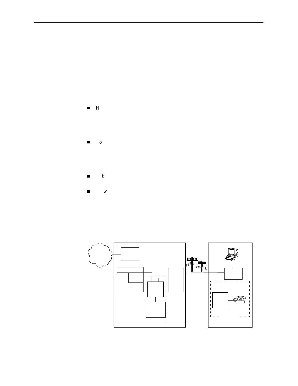
The following illustration sh ow s a typica l Hotwire system with a Hotwire DSL
Router. All Hotwire DSL routers transport data. The Hotwire 6371 RADSL Router
can transport data and POTS simultaneously.
Customer Premises (CP)
Data
Interface
SN
POTS
Voice
Interface
CP
POTS
Splitter
Optional
Network
Service
Provider
Central Office (CO)
Hotwire
IPC
ATM
SCM
DSL
CARD
GranDSLAM
CO
POTS
Splitter
Switched
Network
Optional
MDF
POTS/DSL
Legend: DSL – Digital Subscriber Line IPC –Interworking Packet Concentrator
1-2
March 2002 6300-A2-GB20-00
MDF – Main Distribution Frame POTS –Plain Old Telephone Service
SN – Service Node
01-16968
Page 17

Hotwire DSL Router Features
Hotwire DSL routers contain the following features.
1. Introduction to Hotwire DSL Routers
IP rout ing with
:
— NAT (Network Address Translation)
— NAPT (Network Address Port Translation), also called PAT (Port Address
Translation)
— Simultaneous Basic NAT (for several fixed servers) and NAPT (on the rest
of the PCs on the LAN)
— DHCP Server (Dynamic Host Configuration Protocol) and DHCP Relay
Agent
— A full set of IP filters, two per DSL card (one for upstream and one for
downstream traffic), with up to 33 rules per filter
— SNMP Set/Get capability
Three Configurable Modes of Operation.
Supports the following modes of
operation:
— IP routing only
— IP routing, and bridging of all other protocols (using VNET mode)
— Bridging all protocols (using VNET mode)
Protocol Filters.
Provides th e ab ilit y to:
— Filter MAC frames when bridging
— Configure two Ethertype filters via the Hotwire DSL card, one for upstream
and one for downstream traffic, with up to 16 f ilter rules per filter
— Compare the Ethertype in frames to a particular value, or configured set of
values, to perform filtering
— Support ICMP (Inter net Control Manage men t Protocol) filters for firewalls
via the Hotwire DSL card, based on the ICMP message type, to
selectively discard some ICMP message types while forwarding others
High-speed Internet or intranet access.
Diagnostics.
Provides the capability to diagnose device and network
problems and perform tests.
Device and Test Monitoring.
Provides the capability of tracking and
evaluating the unit’s operation.
Remote Firmw are D own load.
Provides easy setup and activation of
firmware upgrades from a remote location.
Security.
Provides multiple levels of security, which prevents unauthorized
access to the DSL router.
6300-A2-GB20-00 March 2002
1-3
Page 18

1. Introduction to Hotwire DSL Routers
In addition, the following features are provided for the Hotwire 6351 ReachDSL
Router:
Service Subscriber
The Service Subscriber is the user (or set of users) that has contracted to receive
networking services (e.g., Internet access, remote LAN access) for the end-user
system from an NSP (Network Service Provider). Service subscribers may be:
Console Terminal Interface.
Provides an interface for:
— Configuring and managing the DSL router
— Local console access
Management from an NMS usi ng SNMP.
Telnet access to the Command Line Interface (CLI) in the service domain for
Network Service Provider (NSP) use.
TFTP client support for NSP service domain software downloads.
SYSLOG availa bilit y in the s e rvice dom a in.
Point-to-Point Protocol over Ethernet (PPPoE) client provided as defined in
RFC 2516.
Asymmetric maximum upstream /downstream setting.
Residential users connected to public network services (e.g., the Internet)
Work-at-home users connected to their corporate intranet LAN
Commercial users at corporate locations (e.g., branch offices) connected to
other corporate locations or connected to public network services
A Hotwire DSL Router must be installed at the customer premises to provide the
end user with access to any of the above services.
NOTE:
If you would like more information on DSL-based services, applications, and
network deployment, refer to Paradyne’s
The DSL Sourcebook.
may be downloaded or ordered through Paradyne’s World Wide Web site at
www.paradyne.com/library
.
The book
1-4
March 2002 6300-A2-GB20-00
Page 19

Accessing the DSL Router
Access Control to the DSL Router
The Hotwire DSL Router can be managed from an NMS using SNMP or from the
Command Line Interface (CLI). There are several methods av ai lab l e for accessing
the command line interface:
Local access at the DSL router through the Console port.
Access by a Telnet session (controlled through the management interface at
the Hotwire chassis).
For the Hotwire 6351 ReachDSL Router, access by a Telnet session from the
service domain.
2
Levels of Access
The Hotwire DSL Router accepts only one login session at a time.
There are two levels of privileges on the Hotwire DSL system:
Administrator
— Administrator, non-configuration mod e: Provide s read-onl y capabilities.
This is the same level of access as Operator.
— Administrator, configuration mode: Provides complete write access to the
DSL router.
Operator
with no modification permission and no access to managem ent functions.
Refer to Appendix A,
command line entry.
For local console access, the Operator and Administrator have the same Login ID ,
but with different passwords for their access level. For Telnet access through the
service domain for the ReachDSL Router, up to four login/password/access level
combinations can be configured.
. The Administrator has two levels of access to the DSL router.
. The Operator has read-only access to display device information
Command Line Interface
, for access level details f o r ea ch
6300-A2-GB20-00 March 2002
2-1
Page 20

2. Accessing the DSL Router
Local Con s ole Access
Your user account can be configured with one user login name and different
passwords for accessing a CLI session. The DSL router ships with the local
console enabled. After login, the local console can be disabled.
To disable with the local console, type:
Press Enter after each command that you type.
console disable
save
exit
Entering
you attempt to log in, you will receive an error message.
After saving this change and ending the session, there is no local access
through the console port. Any access must be through a Telnet session or
the NMS.
To deter m ine via a Telnet session whether a console is enabled, enter:
show console
One of the following messages is returned:
—
console enabled
console.
—
console disabled
console.
Changing Access Session Levels
To change the Admin istrator access level, enter:
admin enable
This command provides Administrator access privileges. The router responds
with a prompt to enter the password for Ad ministrator access.
console disable
– Command line management is available at the
– No command line management is av ailable at the
results in NO local access to the DSL router. If
To end the Administrator access level, enter:
admin disable
This command ends the Administrator session. No password is needed.
Entering
page 2-7 for further details on ending a session.
To determine the access lev el fo r a session, refer to
Access Level
2-2
March 2002 6300-A2-GB20-00
has the same result. Refe r to
exit
on page 2-5.
Exiting from the System
Determining the Current
on
Page 21

Setting Up the New User's Login
A login prompt appears when the local console connection is first established.
When the login prompt appears, a locally connected console defaults to Console
Enabled, with Operator access.
Procedure
To access the router’s CLI for the first-time:
2. Accessing the DSL Router
1. At the initi al
Login>
prompt, type the default login ID
paradyne
and press
Enter.
2. At the
Password>
prompt (for Operator), type the default password
and press Enter. The login ID and password are validated together when a
login is entered.
3. At the system identity of
CUSTOMER>
prompt, type
admin enable
and press
Enter.
4. At the
abc123
Password>
and press Enter.
System identity changes to the Administrator display mode of
5. Type
configure terminal
prompt (for Administrator), type the default password
CUSTOMER#>
and press Enter.
System identity changes to the Administrator configuration mode of
CUSTOMER - CONFIG#>
.
6. To change or add a new login ID, enter text to replace the default of
paradyne
name
:
your new login ID
NOTE:
Login ID and password are NOT case-sensitive .
abc123
.
7. Enter a new password and specify the level:
password
Example: Type
level passw ord
password operator 238clrd3
Both the login ID and password are 1–31 printa ble alphanumeric ASCII
characters, in the ASCII hex range of 0x21–0x7E. No spaces are allowed.
The following ta ble list s invalid ch aracters.
Invalid Characters Value ASCII Hex Translation
#
$
%
&
6300-A2-GB20-00 March 2002
Number sign 0x23
Dollar sign 0x24
Percentage 0x25
Ampersand 0x26
and press Enter.
2-3
Page 22

2. Accessing the DSL Router
Telnet Access
8. At the prompt, enter the new Administrator-level password to replace
password admin
save
new password
abc123
NOTE:
Any input during an Administrator configuration session must be saved
while still in c on f igu r ati o n mo de.
If denied access during a Telnet session, the session stops and an error is l ogged.
If accessing the router locally and a Telnet session is active, you receive a
Local console disabled by conflict
Telnet access through the management interface in the DSLAM is always enabled
and defaults to Administrator level. For information on accessing the router
through the MCC card in the DSLAM, see the
Communications Controller (MCC) Card, IP Conservative, User's Guide
For the Hotwire 6351 ReachDSL Router, Telnet access from the service domain is
allowed. Telnet Login and a user name and password should be configured if
Telnet access is enabled on the router (the factory default is disable). Up to four
access level/login/password combinations can be configured for the service
domain from which the ReachDSL Router will accept Telnet connections when the
Telnet login feature is enabled.
message.
Hotwire Management
.
:
NOTE:
For network security, Telnet access in the service domain shoul d be disabled
after the the initial remote configuration unless a firewall or some other
security mechanism is used at the subscriber managemen t system. This
ensures that Telnet access to the endpoint is limited to the service provider.
Procedure
To set up Telnet access from the service domain:
1. Type
2. Enable Telnet access form the service domain. Enter:
configure terminal
System identity changes to the Administrator configuration mode of
CUSTOMER - CONFIG#>
telnet enable
save
and press Enter.
.
2-4
March 2002 6300-A2-GB20-00
Page 23

2. Accessing the DSL Router
3. To create a login ID and password for a specified access level, enter:
telnet name create
Example: Type
and press Enter.
telnet name create operator 238clrd3 1234
NOTE:
Login ID and password are NOT case-sensitive . See Step 7 on page 2-3
for list of invalid characters.
4. Enable Telnet log in s o tha t the ReachDSL R ou t e r w ill p er form login and
password validation for the Telnet session connection. Enter :
telnet login enable
save
NOTE:
Any input during an Administrator configuration session must be saved
while still in c on f igu r ati o n mo de.
Determining the Current Access Level
The command line prompt displays the access level. The factory default for
System identity is
replace
CUSTOMER
CUSTOMER>
. See the examples below.
. You can set your own system identity name to
lev el login ID password
If the prompt format
appears as . . .
CUSTOMER> PARADYNE> Operator, display mode
CUSTOMER #> PARADYNE #> Administrator, display
CUSTOMER – CONFIG#> PARAD YNE – CONFIG#> Administrato r,
Determining the Available Commands
To deter m ine the comm ands available at the current login access level, enter any
of the following:
help
(question mark)
?
the command, without any parameters
Or, if a System identity of
PARADYNE is entered, the
prompt displays . . .
Then th e D SL rout er
access level is . . .
mode
configur ation mode
6300-A2-GB20-00 March 2002
2-5
Page 24

2. Accessing the DSL Router
Using the List Command
The list command displays a sequence of commands in the form of ASCII strings
that would have the eff ect of setting all c onfiguration settings to the current val ues.
Secure information such as passwords and login IDs are not displayed.
To deter m ine the comm ands available, enter Administrator configuration mode
and type either:
list
Displays the output in on-screen page mode. In on-screen page mode, the
user interface displays 23 lines of information. When the 24th line is reached,
More...
list config
Displays the output in scroll mode as a text file. Scroll mode captures and
displays all command strings in a text file for use with a terminal emulation
program. Refer to Appendix D,
appears. Pressing any key displays the next page.
DSL Router Ter minal E mulation.
Changing the System Identity
The System identity is the same as the MIB entry of sysName. The sysCo n ta ct
and sysLocation MIB entries are not displayed.
Procedure
To change System identity from the factory default of
1. Log in and enter ADMIN-configuration mode.
2. At the
CUSTOMER-CONFIG#>
(no spaces allowed) and press Enter. Then type
system identity
For example:
system identity PARADYNE
save
In this example, after saving the entry and end ing configuration mode, the
System identity will display:
PARADYNE#>
Refer to
Exiting from the System
CUSTOMER>
prompt, type the new System identity
and press Enter.
save
new system identity
on page 2-7 to end configuration mode.
:
2-6
March 2002 6300-A2-GB20-00
Page 25

Exiting from the System
You can manually log out of the system, or let the system automatically log you
out. The DSL router will log you out immediately if you disconnect the Console
cable. Any unsaved configuration input will be lost.
Manually Logging Out
2. Accessing the DSL Router
To log out, there are two commands:
logout
and
exit
.
Procedure
To log out of a CLI session:
1. At the > prompt, type
logout
and press Enter.
2. The system ends the session immediately. Any configuration updates must
be saved before exiting or the updates will be lost.
Procedure
To exit the DSL router’s current acce ss level:
1. At the > prompt, type
configuration changes, you will be prompted to save changes before exiting.
2. The
command has the following effect:
exit
I f accessing the DSL router . . . Then . . .
At the Local console and logged in at
the Administrator level, configuration
mode
and press Enter. If there are any unsaved
exit
You are placed at the Operator level. Any
configuration updates must be saved or
they will be lost.
At the Local console and logged in at
the Administrator level,
non-configuration mode
At the Local console and logged in at
the Operator le vel
Via a Telnet session and logged in at
any access level
6300-A2-GB20-00 March 2002
You are placed at the Operator level.
exit
The
the Logout command.
Entering either of the following imm ediately
ends the Telnet session:
command responds exactly like
exit
Ctrl + ]
(Control and right bracket k eys)
2-7
Page 26

2. Accessing the DSL Router
A utom atically Logging Out
The DSL router has an automatic timeout feature that logs you out of the system
after five minutes of inactivity. Unsaved configuration input is lost. The default for
the
autologout
command is enable.
When
autologout
Enabled, the system inactivity timer is enabled.
Disabled, the system inactivity timer is disabled.
To log back in, press Enter at the console to display the
is:
Login>
prompt.
For Telnet access through the service domain for the ReachDSL Router, the Telnet
session is automatically closed after a user-configurable number of minutes. The
default for the
timeout
telnet timeout
command overrides the 5-minute limit enabled by the
command. Also, the
telnet keep-alive
command is 5 (minutes). The
command can be enabled which
telnet
autologout
allows the ReachDSL Router to close the Telnet session if it detects that the
service domain Telnet client has crashed and is down or has rebooted.
2-8
March 2002 6300-A2-GB20-00
Page 27

Configuring the DSL Router
DSL Router Configuration Overview
Hotwire DSL Routers support various customer premises distr ibution networks
that contain IP forwarding devices or routers, as well as locally attached hosts
or sub nets. The Hotwire DSL Router’s IP Routing Table contains IP address and
subnet mask information.
The DSL router supports Intern et Protocol, as specified in RFC 791, and Internet
Control Message Protocol (ICMP), as specified in RFCs 792 and 950. It acts as a
router (or gateway), as defined in RFC 791. It also acts as a bridge, bridging all
traffic in the service domain, or routing IP traffic and bridging all other traffic in the
service domain, without affecting traffic in the management domain.
3
For more information on suppor t ed RFCs, refer to
The DSL Router’s Interfaces
Hotwire DSL Routers have two interfaces, the DSL interface and the Ethernet
interface.
DSL Interface
The router’s interface type is determined by its model number:
— Models 6301 and 6302 are Hotwire IDSL Routers.
— Models 6341 and 6342 are Hotwire SDSL Routers.
— Model 6351 is the Hotwire ReachDSL Router.
— Model 6371 is the Hotwire RADSL Router.
The DSL interface has a unique MAC address, assigned before the router is
shipped.
Appendix C, Traps and MIBs.
6300-A2-GB20-00 March 2002
3-1
Page 28

3. Configuring the DSL Router
Ethernet In t e rface
— The Ethernet interface is a 10/100BaseT interface that automatically
negotiates the rate to be used, 10 Mb or 100 Mb. If all Ethernet-attached
devices are capable of operating at 100 Mb, the router defaults to
100 Mb. Otherwise, it operates at 10 M b.
— The interface can be configured for either DIX or IEEE 802.3 frame
format. When configured to use IEEE 802.3 format, SNAP encapsulation
is used, as specified in RFC 1042.
— The interface has a unique MAC address, assigned before the router is
shipped.
— Hotwire 6302 IDSL and 6342 SDSL Routers have a hub configuration
(separate pins for input and output) with four Ethernet connectors. The
hub acts as a bit-level repeater, with the four Ethernet interfaces logically
appearing as one Ethernet communicat ions interface with a single
collision domain.
— In router mode, the router only accepts transmissions on the Ethernet
interface with the interface’s MAC address, or a broadcast or multicast
MAC address.
— In bridge mode, the router accepts all transmissions.
setting.
Interface Identifiers
The following conventions are used for naming router interfaces:
(or d0) – Identifier for the DSL interface.
dsl1
(or e0) – Identifier for the Ethernet interface.
eth1
With exception to primary status, an interface cannot be deleted or changed as
long as there is a declared route that uses the interface.
Service Domain IP Address Assignments
Hotwire DSL Routers support multiple service domains.
Service domains are defined by the configured network addresses and subnet
masks using the CLI.
Up to four service domain IP addr esses and su bnet masks can be assigned to
each DSL (
) or Ethernet (
dsl1
eth1
This is the def ault
) interface.
When a numbered interface is designated as the primary interface, that interface’s
IP address is used as the Router ID. If no interface is designated as the primary
interface, the last numbered interface that was created becomes the Router ID.
3-2
March 2002 6300-A2-GB20-00
Page 29

Numbered DSL or Ethernet Interface
In this scenario, the hosts attached to the DSL router’s Ethernet interface are on a
different logical network than the core router. The DSL router is the next hop router
for the hosts. The DSL router’s upstream next hop router is the core router.
Simplified Network Topology
3. Configuring the DSL Router
Core
Router
Hosts can be assigned IP addresses on the network attached to the DSL router’s
Ethernet interface either statically or dynamically using DHCP. The upstream next
hop router is assigned an address on a different logical network than the hosts.
To configure the router’s interfaces using this scenario, you must:
Enable routing on the DSL router.
Assign an IP address to the Ethernet interface, eth1.
Assign an IP address to the DSL interface, dsl1.
Assign an upstream next hop router (not necessary necessary when using
FUNI/MPOA DSL link encapsulation or when the PPPoE client is enabled).
Unnumbered DSL Interface
In this LAN extension application scenario, hosts connected to a corporate
network for virtual office connections or telecommuters want to look like they are
on the same network as the core router. The core router is the next hop router
for the hosts and is on the same logical networ k as the hosts. This is not the
same as enabling Bridging mode.
WAN
DSL
Router
Host
(End Users)
99-16609
To configure the router’s interf a ce s for this scenario, you must:
Enable routing on the DSL router.
Assign an IP address to Ethernet interface (eth1).
Specify the DSL interface (dsl1) as unnumbered.
Assign an upstream next hop router (not necessary necessary when using
FUNI/MPOA DSL link encapsulation or when the PPPoE client is enabled).
Enable Proxy ARP for both the eth1 and dsl1 interfaces (not necessary to
enable Proxy ARP on the dsl1 interfac e when using FUNI/MPOA DSL link
encapsulation or when the PPPoE client is enabled).
6300-A2-GB20-00 March 2002
3-3
Page 30

3. Configuring the DSL Router
IP Routing
Hotwire DSL Routers use destination-based routing for downstream traffic. An IP
Routing Table is maintained to specify how IP datagrams are forwarded
downstream. The DSL Router is capable of supporting static routes configured by
the user. This table can be viewed by both Operator and Administrator access
levels.
The DSL router uses source-based forwarding for upstream traffic to ensure that
packets are forwarded to the upstream router specified for the configured service
domain.
Refer to Chapter 4,
IP Options Processing
The DSL router handles and processes IP datagrams with options set as
described below. No command is available to set IP options.
The router does not process (and drops) any IP datagrams with the following IP
options:
Loose source and record route (type 131)
Strict source and record route (type 133)
Security (type 130)
Stream ID (type 136)
The router does process IP datagrams with the following IP options, but does not
provide its IP address or timestamp information in the response message:
Record route (type 7)
Timestamp (type 68)
DSL Router Configuration Examples,
for further details.
3-4
March 2002 6300-A2-GB20-00
Page 31

Network Considerations
The routers can be configured to function in a variety of network environments.
The following sections provide descriptions of some of the router’s features:
3. Configuring the DSL Router
Address Resolution Protocol (ARP)
Proxy ARP
Network Address Translation (NAT)
—
Basic NAT
—
Network Address Port Tr anslation (NAPT/PAT)
—
Simultaneous Basic NAT and NAPT
Dynamic Host Configuration Protocol (DHCP) Server
DHCP Relay Agent
Security
—
IP Protocol Type Filtering
—
Ethernet Ty pe Fi lterin g
—
Land Bug/Smurf Attack Prevention
Routed vs. Bridged PDUs
PPPoE Client Support
on page 3-6
on page 3-10
on page 3-11
on page 3-13
on page 3-14
on page 3-5
on page 3-7
on page 3-9
Address Resolution Protocol (ARP)
Address Resolution Protocol, as specified in RFC 826, is supported in the router.
Up to 265 ARP T abl e entries are supported, and a timeout period for complete and
incomplete ARP Ta ble entries can be configured.
NOTE:
ARP is not available on the DSL interface when PPPoE is enabled for the
ReachDSL Router.
ARP requests and responses are not processed on the DSL interface when the
interface is configured to support RFC 148 3 PDU routing (Standard mode). Refer
to
Routed vs. Bridged PDUs
on page 3-13 for more information.
6300-A2-GB20-00 March 2002
3-5
Page 32

3. Configuring the DSL Router
Operating mode (Standard or VNET) can be changed without reconfiguration of
the router. Static ARP entries can be configured, regardless of the current
operating mode. If static ARP entries are configured, they remain in the database
and can be displayed using the
Using CLI commands, you can:
Proxy ARP
The DSL router supports Proxy ARP. Proxy ARP responses are based on the
contents of the IP Routing Table for service domain traffic. The table must have
entry information that indicates what hosts can be reached on the Ether net
interface, including hosts for whic h the router will not forward p a ckets be c au s e o f
IP filters. For additional information on filtering, see
page 3-11.
show arp
Create up to 64 static ARP Table entries.
Displa y the ARP Table.
Delete ARP Table entries.
Display and delete automatically added ARP Tab le entries made by the DHCP
server and relay functions. Refer to
(DHCP) Server
on page 3-9.
CLI command.
Dynamic Host Configuration Protocol
IP Protocol Type Filter ing
on
Proxy ARP is not available on the DSL interface when the router is configured to
support RFC 1483 PDU routing. See
more information.
If an ARP request is received on one interface, and the requested IP address can
be reached on the other interface, the router responds with its own MAC address.
Using CLI commands, you can enable and disable Proxy ARP for each interface.
Routed vs. Bridged PDUs
on page 3-13 for
NOTES:
— When Basic NAT is enabled, the DSL interface (dsl1) must have Proxy
ARP enabled when the dsl1 interface address is part of the Basic NAT
global IP network address.
— Proxy ARP is not available on the DSL interface when PPPoE is enabled
for the R eachDSL Router.
3-6
March 2002 6300-A2-GB20-00
Page 33

Network Address Translation (NAT)
The DSL router provides NAT, as described in RFC 16 31, IP Network Address
Translator (NAT).
access the external (public or global) network using either a block of public IP
addresses (Basic NAT) or a single IP address (NAPT). Static mapping enables
access to selected local hosts from outside using these external IP addresses.
NAT is used when a private network’s internal IP addresses cannot be used
outside the private network. IP addresses may be restricted for privacy reasons, or
they may not be valid public IP addresses.
Simultaneous Basic NAT and Network Address Port Translation (NAP T) is
supported. Refer to
information.
Basic NAT
Basic NAT allows hosts in a private network to transparently access the external
network by using a block of public addresses. Static mapping enables access to
selected local hosts from the outside. Basic NAT is often used in a large
organization with a large network that is set up for internal use, with the need for
occasional external access.
NAT allows hosts in a private (local) network to transparently
Simultaneous Basic NAT and NAPT
3. Configuring the DSL Router
on page 3-8 for additional
Basic NAT provides a one-to-one mapping by translating a range of assigned
public IP addresses to a similar-sized pool of private addresses (typically from the
10.
host appears to have an unique IP address.
address space). Each local host currently communicating with a external
x.x.x
IP addresses
A total of 256 IP addresses can be allocated for use with Basic NAT. Two IP
addresses are reserved, and 254 IP addresses are available for use. Up to
64 static mappings can be configured.
Network Address Port Translation (NAPT/PA T)
NAPT allows multiple clients in a local network to simultaneously access remote
networks using a single IP address. This benefits telecommuters and SOHO
(Small Office/Home Office) users that have multiple clients in an office running
TCP/UDP applications. NAPT is sometimes referred to as PAT (Port Address
Translation).
NAPT provides a many-to-one mapping and uses one public address to interface
numerous private users to an external network. All hosts on the global side view
all hosts on the local side as one Internet host. The local hosts continue to use
their corporate or private addresses. When the hosts are communicating with
each other, the translation is based on the IP address and the protocol por t
numbers used by TCP/IP applications.
6300-A2-GB20-00 March 2002
3-7
Page 34

3. Configuring the DSL Router
Simultaneous Basic NAT and NAP T
Simultaneous Basic NAT and NAPT (or PAT) is supported. In this mode, the
servers (private IP addresses) using Basic NAT are configured and the devices
(private IP addresses) using NAPT are optionally configured (static mappings). If
not configured, the remaining private IP addresses default to NAPT.
Enabling Basic NAT does not disable NAPT . When both Basic NAT and NAPT are
enabled, Proxy ARP can also be enabled, although it is only used for Basic NAT.
Applications Supported by NAT
The DSL routers support the following applications and protocols:
FTP
HTTP
Ping
RealPlayer
Telnet
TFTP
3-8
March 2002 6300-A2-GB20-00
Page 35

3. Configuring the DSL Router
Dynamic Host Configuration Protocol (DHCP) Server
The router provides a DHCP Server feature, as specified in RFC 2131, Dynamic
Host Configuration Protocol, and RFC 2132, DHCP Option and BOOTP Vendor
Extensions. DHCP is the protocol used for automatic IP address assignment.
DHCP setup considerations:
The range of IP addresses to be used by the DHCP server must be
configured. The maximum number of clients is 256.
The DHCP server is not activated until one IP address and subnet mask are
assigned to the Ethernet interface and routing is enabled.
The DHCP server must be enabled, and the DHCP server and DHCP relay
functions cannot be enabled at the same time.
When the DHCP IP address range is changed, all binding entries,
automatically added routes, and ARP T able entries for the clients configured
with the old address range are removed.
When the DHCP Server is enabled, there can be only one IP address
configured for the service domain (Ethernet interface).
The IP address for the next hop router provided to the hosts in the DHCP reply
must be configured.
The subnet mask can be configured along with the IP address range
(optional).
The DHCP server domain name can be configured (optional).
The Domain Name Server (DNS) IP address can be configured (optional).
A minimum and maximum lease time setting can be configured.
For additional information, refer to Chapter 4,
DSL Router Configuration
Examples.
6300-A2-GB20-00 March 2002
3-9
Page 36

3. Configuring the DSL Router
DHCP Relay Agent
The router provides the capability of serving as a DHCP Relay Agent, as specified
in RFC 2131, Dynamic Host Configuration Protocol. The router provides the
capability to enable and disable the DHCP Relay Agent and to configure the IP
address of the DHCP server to which the DHCP requests are to be forwarded.
The DHCP server assigns an IP address to the end-user system. When DHCP
Relay is enabled, it is possible to limit the number of DHCP clients. The IP Routing
Table and ARP Ta ble are automatically updated. The DHCP relay agent in the
router should be used when there is a DHCP server upstream in the service
domain.
DHCP relay agent setup considerations include the following:
DHCP server IP address must be configured.
DHCP relay and routing must be enabled; that is , bot h the server address and
the interface closest to the server are configured.
The number of DHCP clients can be limited to 1–256.
DHCP server and DHCP relay functions cannot be enabled at the same time.
NAT and DHCP relay cannot be enabled at the same time.
3-10
March 2002 6300-A2-GB20-00
Page 37

Security
3. Configuring the DSL Router
The router offers security via the following:
Filtering. A filter consists of a set of rules applied to a specific interface to
indicate whether a packet received or sent on that interface is forwarded or
discarded. Filters are applied to traffic in either the inbound (from the Ethernet
port) or outbound (from the DSL port) direction on that interface:
— IP Protocol Type: TCP, UDP, or ICMP
— ICMP Message Type, Code
— TCP/UDP Ports
— Source/Destination IP Address
— Ethernet Type
Always enabled:
— Land Bug Prevention
IP Protocol Type Filtering
By default, IP Protocol Type (IP) filtering is disabled on the Hotwire DSL card for
the DSL router. If enabled, filtering provides security advantages on LANs by
restricting traffic on the network and hosts based on the source and/or destination
IP addresses.
There is one filter per direction, with a maximum of 33 rules per filter. For IP filters,
all filter access rules with a source host IP address are applied first, with all rules
with a destination host IP address applied next. The remaining filters are applied in
the order in which they were configured.
For additional information about IP filtering, refer to the
RADSL, IDSL, and SDSL Cards, Models 8310, 8312/8314, 8510/8373/8374,
8303/8304, and 8343/8344, User's Guide
— Smurf Attack Prevention
NOTE:
All Hotwire DSL Router filters are configured on the Hotwire DSL card. Some
routing parameters that affect filtering, such as enabling bridging or routing,
can only be configured on the DSL router.
Hotwire MVL, ReachDSL,
.
6300-A2-GB20-00 March 2002
3-11
Page 38

3. Configuring the DSL Router
Ethernet Type Filtering
Ethernet Ty pe filteri ng (Ether t ype) does not apply when the DSL router is in
router-only mode. By default, Ethertype filtering is disabled on the Hotwire DSL
card for the DSL router. If enabled, separate Ethertype filters are applied to the
Ethernet and/or DSL interface with one filter per interface direction. There is a
maximum of 16 rules per list. Each rule access list allows filtering of a single
Ethertype or a range of Ether types.
MAC frames can be filtered based on the:
For Ethertype filters, the rules are applied in the order in which they were
configured. For additional information about Ethertype filters, refer to the
MVL, ReachDSL, RADSL, IDSL, and SDSL Cards, Models 8310, 8312/8314,
8510/8373/8374, 8303/8304, and 8343 /8344, User's Guide
SNAP Ethernet field in the 802.3 header.
Protocol type field in the DIX Ethernet header.
Hotwire
.
Land Bug/Smurf Attack Prevention
Land Bug and Smurf Attack prevention are enhanced firewall features provided
by the router.
Land Bug
interface when the source IP address is the same as the destination IP
address. This prevents the device from being kept busy by constantly
responding to itself.
Smurf Attack
and Ethernet interfaces, or send an ICMP echo reply to the broadcast
address. This ensures that a legitima te user w ill be able to use the network
connection even if ICMP echo/reply (smurf) packets are sent to the broadcast
address.
– The router drops all packets received on its DSL or Ethernet
– The router does not forward directed broadcasts on its DSL
3-12
March 2002 6300-A2-GB20-00
Page 39

Routed vs. Bridged PDUs
The router supports both the VNET model and 1483 Routed model (derived from
RFC 1483) for the transportation of PDUs (Protocol Data Units) from the DSL
router to the router in the core network. When operating in Standard mode, the
DSL router in conjunction with the DSL line card with an ATM uplink (for example,
Model 8304, 8344, etc.) supports routed PDUs. When operating in VNET mode,
the DSL router in conjunction with the DSL line card with an ATM uplink supports
bridged PDUs only.
NOTE:
Standard mode vs. VNET mode is configured on the DSL card at the
DSLAM/GranDSLAM chassis by changing the link encapsulation on the DSL
port.
Both ends of the network (e.g., the DSL router and the DSL line card and the core
router) must be configured to operate the same way (i.e., routed or bridged).
If Using This Network Model . . . Then These DSL Cards Can Be Used . . .
3. Configuring the DSL Router
1483 Routed or Bridged
(Standard Mode)
1483 Bridged (VNET Mode)
Model 8304 24-port IDSL
Model 8314 12-port ReachDSL
Model 8344 24-port SDSL
Model 8374 12-port RADSL
Models 8303/8304 24-port IDSL
Models 8312/8314 12-port ReachDSL
Models 8343/8344 24-port SDSL
Models 8373/8374 12-port RADSL
Model 8510 12-port RADSL
6300-A2-GB20-00 March 2002
3-13
Page 40

3. Configuring the DSL Router
Figure 3 -1, 1483 Routed Networ k Model (Standard mode) , illustrates the
1483 Routed model (Standard mode) in the network.
FUNI = Frame-based User-to-Network Interface
NSP's
Access
Device
NAP's
Core
Router
NSP's
Access
Device
NAP's ATM
Network
P
O
W
E
R
O
I
IPC Hotwire
GranDSLAM
A
L
A
R
M
S
nBA
Ma
j
o
r
M
inorFa
Client
DSL
Router
Client
IP/MACIP/1483/FUNIIP/1483/ATM
00-16802
Figure 3-1. 1483 Routed Network Model (Standard mode)
PPPoE Client Support
The Hotwire 6351 ReachDSL Router supports a PPPoE client as defined in
RFC 2516, allowing PPPoE functionality to be moved from the PC clients to the
ReachDSL Router. See
Interface
PPPoE client support can only be enabled on the Hotwire 6351 ReachDSL Router
when:
In addition to using the CLI to enable PPPoE suppor t, the CLI can be used to
specify the interface to assign the IP address negotiated during the network-layer
protocol phase of PPP (the default is the DSL interface).
, for information on configuring PPPoE client support.
The router is configured for IP Routing (bridging must be disabled),
The router must be in VNET mode,
Proxy ARP for the DSL interface must be disabled, and
No upstream next-hop route should be defined for the DSL interface.
PPPoE Client Commands
in Appendix A,
Command Line
3-14
March 2002 6300-A2-GB20-00
Page 41

When the n eg o tiated IP
address is assigned to the . . . Then . . .
3. Configuring the DSL Router
Ethernet interf ace of the
ReachDSL Router
DSL interface of the
ReachDSL Router
The DSL interface will automatically be configured as
unnumbered , and any IP address(es) previously
assigned to the Ethernet and DSL interfaces are
remov ed. A route for the subnet defined by the
negotiated I P address assigned to the Ethernet inter face
will automatically be added to the IP routing table.
Any IP address(es) previously assigned to the DSL
interf ace are removed. The I P address(es) assigned to
the Ethernet interface are left intact unless they confli ct
with the negotiated IP address. The IP address used by
the Ethernet interface must be assigned by the user.
Once the PPP-negotiated IP address is assigned, the ReachDSL Router’s
configuration database will automatically be converted to a new configuration
determined by this IP address and the interface to which it is assigned. However,
any changes made to the interface assignment for the PPP-negotiated IP address
do not take effect until the next time the PPP link is established. This new
configuration will result in the following:
The DSL and/or Ethernet interface(s) are reconfigured.
Routes associated with any interfaces that have been removed are deleted.
An exception to this is when the negotiated IP address is assigned to the
Ethernet interface and the subnet defined by the interface’s IP address is the
same as the one defined by the negotiated IP address.
All dynamic ARP entries are removed. All static ARP entries associated with
the DSL interface and any removed interfaces are deleted. Static ARP entries
for the Ethernet interface are retained if the negotiated IP address is assigned
to the Ethernet interface and the subnet defined by the interface’s IP address
is the same as the one defined by the negotiated IP address.
The negotiated IP address automatically becomes the primary IP address and
the NAPT public IP address.
An active service domain Telne t session is ter m inated if the interface
associated with the session is removed or the IP address of the interface is
changing.
All DHCP bindings and BOOTP Relay Agent snoop information are removed if
the subnet defined by the Ethernet IP address changes. If t he new Ethernet IP
address is still in the same subnet, then only the bind ing and snoop
information that conflicts with this IP address is removed.
If the DSL interface IP address changes, the Basic NAT static mapping that
conflicts with the new DSL IP interface address and all Basic NAT dynamic
mappings are removed.
6300-A2-GB20-00 March 2002
3-15
Page 42

3. Configuring the DSL Router
3-16
March 2002 6300-A2-GB20-00
Page 43

DSL Router Configuration Examples
Configuration Examples
The Hotwire DSL Router configuration examples in this chapter include only a
few of the possible scenarios. This chapter covers some of the common
configurations. The command syntax will vary based on your network setup.
Configuration commands require the access level of Administrator-Config and
changes need to be saved while in configuration mode to take effect. Refer to
Chapter 2,
The Hotwire DSL Router configuration examples include:
Accessing the DSL Router
4
.
Basic Bridging Configuration Example
Basic Routing Configuration Example
Basic NAT Configuration Example
NAPT Configuration Example
Simultaneous Basic NAT and NAPT Configuration Examp le
Unnumbered DSL Interface with Proxy ARP Configuration Example
DHCP Relay with Proxy ARP Configuration Example
DHCP Server with Basic NAT Configuration Example
PPPoE Client with NAPT and DHCP Server Configuration Example
Downstream Router Configuration Example
Refer to Appendix A,
syntax. Ref er to Appendix B,
Shortcuts
syntax.
, for specific command default settings and abbreviated command line
Command Line Interface,
Configuration Defaults and Command Line
for specific commands and their
6300-A2-GB20-00 March 2002
4-1
Page 44

4. DSL Router Configuration Examples
NOTES:
— Configuration examples included in this chapter cover some common
configurations, providing only a few of the possible scenarios.
— IP addresses used in the examples are for illustrative purposes only; they
are not intended to be used when configuring your local network.
— Adding static routes to the core router is typically necessary when routing
is enabled.
— Bridging-only mode is the default configuration.
Basic Bridging Configuration Example
This is the factory default configuration. To return the DSL router to the factory
default configuration, use the following command:
configure factory
.
Core
Router
155.1.3.1
WAN
DSL
DSL
Router
Customer Premises (CP)
Console
Port
Connection
Ethernet
Hub
155.1.3.2
155.1.3.3
155.1.3.4
155.1.3.5
IP, IPX,
Apple T alk, etc.,
End-user
Systems
01-16966
NOTES:
— When the DSL router is configured for bridging, DSL link encapsulation for
the DSL port must be configured for EtherHDLC at the line card.
— This configuration is only supported with firmware version 4.2.5 or higher.
4-2
March 2002 6300-A2-GB20-00
Page 45

Basic Routing Configuration Example
Core
Router
155.1.4.1
WAN
In this basic routing example:
There are multiple clients with statically assigned public IP addresses
configured on the Ethernet side of the DSL router.
DSL
dsl1
155.1.4.254
DSL
Router
Customer Premises (CP)
Console
Port
Connection
Ethernet
eth1
155.1.3.254
Hub
4. DSL Router Configuration Examples
End-user
Systems
155.1.3.2
155.1.3.3
155.1.3.8
01-16613-02
The IP addresses of the clients are contained within the subnet specified by
the configured Ethernet IP address and subnet mask.
The next hop router (default gateway) of the clients is the Ethernet interface
(eth1) of the DSL router .
The next hop router for downstream forwarding from the core router is the
DSL interface (dsl1) of the DSL router.
The commands and syntax for this example are:
ip
routing enable
ifn
address eth1 155.1.3.254 255.255.255.0
ifn
address dsl1 155.1.4.254 255.255.255.0
ip route create upstream eth1 155.1.4.1
NOTES:
— The
ip routing enable
firmware version 4.2.5 or higher.
— FUNI/MPOA (1483 routed) link encapsulation can be used with this
configuration and the DSL card Models 8304, 8314, 8344, and 8374. Link
encapsulation is configured on the DSL port. This link encapsulation must
match the core network encapsulation type. The
upstream
command is not necessary when using FUNI/MPOA link
encapsulation.
command is only required when using
ip route create
— If IP Scoping is enabled, the clients’ IP addresses must be entered into the
client VNID table.
6300-A2-GB20-00 March 2002
4-3
Page 46

4. DSL Router Configuration Examples
To enable Tel net through the ser vice dom ain via the DSL router Ethernet (eth1)
port, use the following commands:
telnet enable
telnet login enable
telnet name create admin paradyne abc123
Basic NAT Configuration Example
Core
Router
155.1.3.1
WAN
DSL
dsl1
155.1.3.2
DSL
Router
Customer Premises (CP)
Console
Port
Connection
Ethernet
eth1
10.1.3.1
Hub
End-user
Systems
10.1.3.2
10.1.3.3
10.1.3.4
10.1.3.5
00-16767
NAT Mapping Public IP Addresses Private IP Addresses
155.1.3.3 10.1.3.2
155.1.3.4 10.1.3.3
155.1.3.5 10.1.3.4
155.1.3.6 10.1.3.5
In this Basic NAT example:
NAT is used for one-to-one mapping of addresses.
There are four private IP addresses configured on the Ethernet side of the
DSL router, with NAT static mappings to four public IP addresses.
The Ethernet interface (eth1) is in the private address space and the DSL
interface is in public address space.
The next hop router (default gateway) of the clients is the Ethernet IP address
of the DSL router, 10.1.3.1.
Since Basic NAT is enabled and the dsl1 interface address is on the same
subnet as the Basic NAT global IP network address, Proxy ARP must be
enabled on the DSL interface (dsl1). Prox y AR P is not necessar y when using
FUNI/MPOA link encapsulation.
If IP Scoping is enabled, the client’s NAT mapping public IP addresses and the
dsl1 interface IP address must be entered into the client VNID table.
4-4
March 2002 6300-A2-GB20-00
Page 47

4. DSL Router Configuration Examples
The commands and syntax for this example are:
ip routing enable
ifn
address eth1:1 10.1.3.1 255.255.255.0
ifn
address dsl1 155.1.3.2 255.255.255.0
ip route create upstream eth1 155.1.3.1
nat basic address 155.1.3.0
nat basic map 155.1.3.3 10.1.3.2 10.1.3.5
nat basic enable
proxy arp dsl1 enable
NOTES:
— The IP address assigned for the DSL interface and the IP address in NAT
static mappings can be in the same subnet, but cannot be the same IP
address.
— When IP Scoping is enabled, Basic NAT is enabled and the dsl1 interface
is NOT part of the Basic NA T global IP network, only the dsl1 interface’s I P
address must be entered into the client VNID table.
— The
— FUNI/MPOA (1483 routed) link encapsulation can be used with this
ip routing enable
firmware version 4.2.5 or higher.
configuration and the DSL card Models 8304, 8314, 8344, and 8374. Link
encapsulation is configured on the DSL port. This link encapsulation must
match the core network encapsulation type. The
upstream
necessary when using FUNI/MPOA link encapsulation.
and
proxy arp dsl1 enable
command is only required when using
ip route create
commands are not
6300-A2-GB20-00 March 2002
4-5
Page 48

4. DSL Router Configuration Examples
NAPT Conf iguration Example
Core
Router
155.1.3.1
WAN
DSL
dsl1
155.1.3.2
DSL
Router
Customer Premises (CP)
Console
Port
Connection
Ethernet
eth1
10.1.3.1
Hub
10.1.3.2
Web Server
10.1.3.3
10.1.3.4
10.1.3.8
End-user
Systems
Telnet
Server
01-16611-03
NAPT Ma p ping Public IP A dd ress es Private I P A dd resses
inbound 155.1.3. 2, destination Port 23 10.1.3.4 (Telnet server)
inbound 155.1.3. 2, destination Port 80 10.1.3.2 (Web server)
In this NAPT example:
The DSL router is configured for NAPT using a single public IP address.
When using NAPT, the DSL interface (dsl1) must be numbered because the
Ethernet interface will be configured within the private address space.
NAPT static mapping is configured for a server (Telnet port 23) on the Ethernet
interface, but the address is publicly available.
The commands and syntax for this example are:
ip routing enable
ifn
address eth1 10.1.3.1 255.255.255.0
ifn
address dsl1 155.1.3.2 255.255.255.0
ip route create upstream eth1 155.1.3.1
nat napt address 155.1.3.2
nat napt map tcp 10.1.3.4 23
nap napt map tcp 10.1.3.2 80
nat napt enable
4-6
March 2002 6300-A2-GB20-00
Page 49

NOTES:
4. DSL Router Configuration Examples
— The
— FUNI/MPOA (1483 routed) link encapsulation can be used with this
— NAPT is limited to one subnet.
ip routing enable
firmware version 4.2.5 or higher.
configuration and the DSL card Models 8304, 8314, 8344, and 8374. Link
encapsulation is configured on the DSL port. This link encapsulation must
match the core network encapsulation type. The
upstream
encapsulation.
command is not necessary when using FUNI/MPOA link
command is only required when using
ip route create
6300-A2-GB20-00 March 2002
4-7
Page 50

4. DSL Router Configuration Examples
Simultaneous Basic NAT and NAP T Configuration Example
The DSL router can be configured for Basic NAT and NAPT simultaneously. In the
private address space, multiple work stations can use NAPT and the servers can
use Basic NAT. This allows a server to support traffic other than TCP/UDP traffic
and accommodate multiple inbound traffic types. Using Basic NAT also allows you
to have multiple servers of the same type (Web, FTP, Telnet) on the private
network. All private addresses not specified in a Basic NAT map command will be
translated via NAPT.
Customer Premises (CP)
Web Server/
FTP/Telnet
10.1.3.2
Core
Router
155.1.3.1
WAN
DSL
dsl1
155.1.3.2
DSL
Router
Console
Port
Connection
Ethernet
eth1
10.1.3.1
Hub
10.1.3.3
Web
Server
10.1.3.6
10.1.3.7
10.1.3.8
01-16967
In this Simultaneous Basic NAT and NAPT example:
Since Basic NAT is enabled and the dsl1 interface address is on the same
subnet as the Basic NAT global IP network address, Proxy ARP must be
enabled on the DSL interface (dsl1).
If IP Scoping is enabled, the client’s NAT mapping public IP addresses and the
dsl1 interface IP address must be entered into the client VNID table.
The commands and syntax for this example are:
ip routing enable
ifn
address eth1 10.1.3.1 255.255.255.0
ifn
address dsl1 155.1.3.2 255.255.255.0
ip route create upstream eth1 155.1.3.1
nat basic address 155.1.3.0
nat napt address 155.1.3.2
nat basic map 155.1.3.3 10.1.3.2 10.1.3.3
nat basic enable
nat napt enable
proxy arp dsl1 enable
4-8
March 2002 6300-A2-GB20-00
Page 51

4. DSL Router Configuration Examples
NOTES:
— When IP Scoping is enabled, Basic NAT is enabled and the dsl1 interface
is NOT part of the Basic NA T global IP network, only the dsl1 interface’s I P
address must be entered into the client VNID table.
— This configuration is only supported with firmware version 4.2.5 or higher.
— FUNI/MPOA (1483 routed) link encapsulation can be used with this
configuration and the DSL card Models 8304, 8314, 8344, and 8374. Link
encapsulation is configured on the DSL port. This link encapsulation must
match the core network encapsulation type. The
upstream
necessary when using FUNI/MPOA link encapsulation.
and
proxy arp dsl1 enable
ip route create
commands are not
6300-A2-GB20-00 March 2002
4-9
Page 52

4. DSL Router Configuration Examples
Unnumbered DSL Interface with Proxy ARP Configuration Example
Customer Premises (CP)
Core
Router
155.1.3.1
WAN
DSL
dsl1
Unnumbered
DSL
Router
Console
Port
Connection
Ethernet
eth1
155.1.3.254
Hub
155.1.3.2
155.1.3.3
155.1.3.4
End-user
Systems
01-16768-01
In this unnumbered DSL Interface with Proxy ARP example:
The clients are statically configured and use the core router as the next hop
router (default gateway) in order to create the LAN extension configuration.
The DSL interface is unnumbered.
The clients, the DSL router’s Ethernet interface, and the core router’s interface
are all on the same logical network.
If IP Scoping is enabled at the DSL card, the eth1 and the client’s IP
addresses must be placed in the client VNID table (VNID mode must be
selected on the DSL cards with an ATM uplink, such as Model 8304, 8344,
etc.).
The commands and syntax for this example are:
ip routing enable
ifn
address eth1 155.1.3.254 255.255.255.0
ifn
address dsl1 unnumbered
ip route create upstream eth1 155.1.3.1
proxy arp eth1 enable
proxy arp dsl1 enable
NOTES:
— The
ip routing enable
firmware version 4.2.5 or higher.
— FUNI/MPOA (1483 routed) link encapsulation can be used with this
configuration and the DSL card Models 8304, 8314, 8344, and 8374. Link
encapsulation is configured on the DSL port. This link encapsulation must
match the core network encapsulation type. The
upstream
and
proxy arp dsl1 enable
necessary when using FUNI/MPOA link encapsulation.
4-10
March 2002 6300-A2-GB20-00
command is only required when using
ip route create
commands are not
Page 53

DHCP Relay with Proxy ARP Configuration Example
4. DSL Router Configuration Examples
DHCP
Server
Core
Router
155.1.3.253
WAN
155.1.3.1
Unnumbered
DSL
dsl1
DSL
Router
Customer Premises (CP)
Console
Port
Connection
Ethernet
eth1
155.1.3.254
Hub
155.1.3.2
155.1.3.3
155.1.3.4
In this DHCP Relay with Proxy ARP example:
The clients are using dynamic IP address assignment and use the core router
as the next hop router (default gateway) in order to create the LAN extension
configuration.
The DSL interface (dsl1) is unnumbered.
The clients, the Ethernet interface (eth1), and the core router interface are all
on the same logical network.
End-user
Systems
01-16612-02
IP Scoping must be disabled at the DSL card.
The DSL router is configured as a DHCP relay.
The commands and syntax for this example are:
ip routing enable
address eth1 155.1.3.254 255.255.255.0
ifn
ifn
address dsl1 unnumbered
ip route create upstream eth1 155.1.3.1
proxy arp eth1 enable
proxy arp dsl1 enable
dhcp relay enable
dhcp relay address 155.1.3.253
NOTES:
— The
ip routing enable
firmware version 4.2.5 or higher.
— FUNI/MPOA (1483 routed) link encapsulation can be used with this
configuration and the DSL card Models 8304, 8314, 8344, and 8374. Link
encapsulation is configured on the DSL port. This link encapsulation must
match the core network encapsulation type. The
upstream
and
proxy arp dsl1 enable
necessary when using FUNI/MPOA link encapsulation.
command is only required when using
ip route create
commands are not
6300-A2-GB20-00 March 2002
4-11
Page 54

4. DSL Router Configuration Examples
DHCP Server with Basic NAT Configuration Example
DNS
Name
Server
132.53.4.2
In this DHCP Server with Basic NAT example:
The clients are using dynamic IP address assignment and use the Ethernet
interface (eth1) of the DSL router as the next hop router (default gateway).
Core
Router
155.1.3.1
WAN
DSL
dsl1
155.1.3.2
DSL
Router
Customer Premises (CP)
Console
Port
Connection
Ethernet
eth1
10.1.3.10
Hub
End-user
Systems
10.1.3.2
10.1.3.3
10.1.3.9
01-16952
The DSL interface (dsl1) must be numbered.
The DSL router is configured as the DHCP server providing the private IP
addresses to the clients.
The Ethernet interface is in private address space. NAT is used for
one-to-one mapping of addresses.
The commands and syntax for this example are:
ip routing enable
ifn
address eth1 10.1.3.10 255.255.255.240
ifn
address dsl1 155.1.3.2 255.255.255.0
ip route create upstream eth1 155.1.3.1
nat basic address 155.1.3.0
nat basic enable
dhcp server addresses 10.1.3.2 10.1.3.9
dhcp server router 10.1.3.10
dhcp server nameserver 132.53.4.2
dhcp server enable
NOTES:
— The
ip routing enable
firmware version 4.2.5 or higher.
command is only required when using
— FUNI/MPOA (1483 routed) link encapsulation can be used with this
configuration and the DSL card Models 8304, 8314, 8344, and 8374. Link
encapsulation is configured on the DSL port. This link encapsulation must
match the core network encapsulation type. The
upstream
command is not necessary when using FUNI/MPOA link
ip route create
encapsulation.
4-12
March 2002 6300-A2-GB20-00
Page 55

4. DSL Router Configuration Examples
PPPoE Client with NAPT and DHCP Serv er Configuration Example
Customer Premises (CP)
DNS
Name
Server
132.53.4.2
In this PPPoE client with NAPT and DHCP server example:
The clients are using dynamic IP address assignment and use the Ethernet
interface (eth1) of the DSL router as the next hop router (default gateway).
SMS
WAN
PPPoE
DSL
dsl1
DSL
Router
Console
Port
Connection
Ethernet
eth1
10.1.3.10
Hub
End-user
Systems
10.1.3.2
10.1.3.3
10.1.3.9
02-17133
The DSL router is configured as the DHCP server providing the private IP
addresses to the clients.
The Ethernet interface is in private address space.
The DSL interface and the NAPT public IP address will be assigned the IP
address negotiated during the network layer protocol phase of PPP.
The commands and syntax for this example are:
ip routing enable
bridging disable
ifn
address eth1 10.1.3.10 255.255.255.0
pppoe enable
ppp authentication chap
ppp username paradyne@network
ppp password abc123
ppp ip dsl1 255.255.255.0
nat napt enable
dhcp server addresses 10.1.3.2 10.1.3.9
dhcp server router 10.1.3.10
dhcp server nameserver 132.53.4.2
dhcp server enable
NOTE:
This configuration is only valid for firmware release 4.3.x or higher.
6300-A2-GB20-00 March 2002
4-13
Page 56

4. DSL Router Configuration Examples
Downstrea m Rout er Configuration Example
Customer Premises (CP)
End-user
Systems
120.26.7.1
Core
Router
155.1.3.1
WAN
DSL
dsl1
155.1.3.2
End-user
Systems
00-16591-01
DSL
Router
Console
Port
Connection
Ethernet
eth1
120.26.7.5
Hub
120.26.7.2
120.26.7.3
120.26.7.100
Router
Hub
130.26.7.1
130.26.7.2
130.26.7.3
In this downstream router example:
There are clients statically configured and connected to the DSL router.
There are also clients connected behind a downstream router.
The DSL interface (dsl1) is numbered.
The next hop router for downstream forwarding from the core router to
networks 120.26.7.0 and 130.26.7.0 is the DSL router’s DSL interface (dsl1).
The commands and syntax for this example are:
ip routing enable
ifn
address eth1 120.26.7.5 255.255.255.0
ifn
address dsl1 155.1.3.2 255.255.255.0
ip route create upstream eth1 155.1.3.1
ip route create 130.26.7.0 255.255.255.0 120.26.7.100
NOTES:
— The
ip routing enable
firmware version 4.2.5 or higher.
— FUNI/MPOA (1483 routed) link encapsulation can be used with this
configuration and the DSL card Models 8304, 8314, 8344, and 8374. Link
encapsulation is configured on the DSL port. This link encapsulation must
match the core network encapsulation type. The
upstream
command is not necessary when using FUNI/MPOA link
encapsulation.
4-14
March 2002 6300-A2-GB20-00
command is only required when using
ip route create
Page 57

Monitoring the DSL Router
Monitoring the Router
The DSL router detects and reports problem conditions that you can monitor. The
following indicators can alert you to possible problems:
LEDs
5
On the DSL router’s front panel. Refer to
Status Messages
For the Ethernet and DSL interface links. Refer to
page 5-3.
Performance Statistics
For service and management domains, Ethernet and DSL interface and links,
IP processing, and bridge operation. Refer to
page 5-3.
SNMP Traps
For the current status of the router’s SNMP traps, if enabled. Refer to
Appendix C,
When a problem is detected, refer to Chapter 6,
for information regarding diagno stic tests, System Log message s, and
troubleshooting.
Traps and MIBs
.
LED Status
Performance Statistics
Diagnostics and Troubleshooting,
on page 5-2.
Interface Status
on
on
6300-A2-GB20-00 March 2002
5-1
Page 58

5. Monitoring the DSL Rout er
LED Status
The Hotwire DSL Router’s front panel includes LEDs (light-emitting diodes) that
provide status on the router and its interfaces. In Table 5-1, Front Panel LEDs, the
Condition in
power-on self-test.
For the Hotwire 6351 ReachDSL Router, the DSL LED is replaced by the LINE
and TX/RX LEDs. Check the LINE LED to determine status of the connection to
the central office; check the TX/RX LED to determine status of data transfer on the
DSL Link.
Table 5-1. Front Panel LEDs
shows what the LED should display after a successful
BOLD
LED Condition Status
PWR
ALM Blinking
TST Blinking
DSL
(all but the
Hotwire 6351
ReachDSL
Router)
LINE
(Hotwire 6351
ReachDSL
Router only)
TX/RX
(Hotwire 6351
ReachDSL
Router only)
ON
ON
OFF
ON
OFF
Blinking
ON
OFF
Blinking
ON
OFF
ON
OFF
The router has power.
A firmware download is in progress. The TST LED is also
blinking alternately during a download.
An alarm condition exists.
No alarms have been detected by the router.
A firmware download is in progress. The ALM LED is also
blinking alternately during a download.
A power-on self -t est or service provider-ini tiated test is in
progress.
No tests are active.
The router is establishing the active DSL lin k. The LED
blinks on and off about five times per second.
The DSL link is ready to transm it and receive data.
No DSL link has been establi shed.
The router is establishing the active DSL lin k. The LED
blinks on and off about five times per second.
The DSL link is established.
No DSL link has been establi shed.
Data transmiss ion is in progress on the DSL line.
No data is being transmitted or received b y the router.
ETHERNET
(The router may
have 1 or 4
Ethernet ports)
5-2
March 2002 6300-A2-GB20-00
ON
OFF
The Ethernet connection is active.
No Ethernet device is detected.
Page 59

Interface Status
5. Monitoring the DSL Router
Current status of the Ethernet (eth1) or DSL (dsl1) interface can be accessed
using the
Information provided about each interface includes the direction of the link, the
MAC address, Proxy ARP setting, the numbered interfaces, their IP addresses
and subnet masks.
show interface
CLI command.
See
show interface {eth1 | dsl1}
Command Line Interf ace
displayed when the command is entered.
NOTE:
The Primary designation of a numbered interface (e.g., eth1:1) marks that
interface as the one that uses its IP address as a Router ID. If no interface is
defined as Primary , t he last numbered interface that was created becomes the
Primary IP Address.
Performance Statistics
Performance statistics are available for the DSL and Etherne t interfaces, for IP
processing, and for the bridge using the
These statistics are above and beyond what is collected and reported at the
DSLAM.
See
show statistics [eth1 | dsl1 | ip | bridge| pppoe | tftp]
on page A-29 in Appendix A,
command and what is displayed when the command is entered.
Clearing Statistics
on page A-26 in Appendix A,
, for information about the command and what is
show statistics
Command Line Interface
CLI command.
, for information about the
The CLI allows you to clear a set of statistics, resetting the counts to zero. Refer to
Clearing Statistics Command
additional information.
6300-A2-GB20-00 March 2002
in Appendix A,
Command Line Interface
, for
5-3
Page 60

5. Monitoring the DSL Rout er
Reasons for Discarded Data
The router may discard frames or packets, shown when the
statistics
CLI command is entered. The following tables list the reasons
show
why those frames and packets were discarded:
Ethernet Interface (Table 5-2)
DSL Interface (Table 5-3)
IP Processing (Table 5-4)
Bridge (Table 5-5)
See
show statistics eth1
Interface
, for additional information.
on page A-29 in Appendix A,
Command Line
Table 5-2. Reasons for Ethernet Interface (eth1) Discarded Frames
Reason
Frame Length Greater than Max (exceeds maximum length allowed)
Receive Buff er Pool Depletion
Pack et Processing Disabled
Unknown Protocol Error
Alignment Error
CRC (Cyclic Redundancy Chec k) Error
FIFO (First In, First Out) Overflow Error
Parity Error
Receiver Halted
Receiver Missed Frame
No Data for Fram e R e port ed as Go od
Bad Len (length) for Frame Reported as Good
Unknown Receive Interrupt Error
Srv (service) Domain Wrpr (wrapper) Tx Queue Overf lows
Srv Domain Phy (physical) Tx Queue Overflows
Srv Domain Receive Queue Over flows
Excessive Collisions
Tx Underflow
Excessive Defers on Tx
Signal Quality Error on Tx
Tx Pari ty Error
Tx Halted
5-4
March 2002 6300-A2-GB20-00
Page 61

5. Monitoring the DSL Router
See
show statistics dsl1
Interface
, for additional information.
on page A-30 in Appendix A,
Table 5-3. Reasons for DSL Interface (dsl1) Discarded Frames
Reason
Alignment Error
Mgmt (management) Domain Phy (physical) Tx Queue O verflows
Mgmt Domain Rcv (received data) Queue Overflows
Mgmt Doma in Tx Link Down Disc ards
Mgmt Domain Wrpr (wrapper) Tx Queue Overflows
Receive Aborts
Receive Buff er Pool Depletion
Receive CRC (Cyclic Redundancy Check) Errors
Receive Frame Too Short or Too Long
Receive Interrupt Errors
Receive Overruns
Receive Unknown Errors
Command Line
Service Domain Rcv (received data) Queue Overflows
Srv (service) Domain Phy Tx Queue Overf lows
Srv Domain Tx Link Down Discards
Srv Domain Wrpr (wrapper) Tx Queue Overflows
Unknown Frame/Protocol Errors
Unrecognized VNID (Virtual Network IDentifier)
6300-A2-GB20-00 March 2002
5-5
Page 62

5. Monitoring the DSL Rout er
See
show statistics ip
Interface
, for additional information.
on page A-30 in Appendix A,
Table 5-4. Reasons for IP Processing Discarded Packets
Reason
Bad Port to Destination
Bad Port to Source
DSL Receive Packets Filtered
DSL Transmit Packets Filtered
Ethernet Receive Packets Filtered
Ethernet Transmit Packets Filtered
Frag mentation Failures
ICMP (Internet Control Management Protocol) Errors
Non-routable Packets
No Route to Destination
No Route to Source
No Upstream Route
Command Line
Other Reassembly Failures
Other Receive Discards
Other Receive Errors
Other Transmit Discards
Pack ets Pending on ARP (Address Resolution Protocol) Discarded
Receive IP Port Disabled
Reassembly Timeout
TCP (Transmission Control Protocol) Errors
Time to Li ve Ex pi re d
Transport Protocol Not Handled
UDP (User Datagram Protocol) Err ors
5-6
March 2002 6300-A2-GB20-00
Page 63

5. Monitoring the DSL Router
See
show statistics bridge
Interface
, for additional information.
on page A-30 in Appendix A,
Table 5-5. Reasons for Bri dg e Discarded Frames
Reason
Broadcast Attempts Dropped
Frames Discarded by Filters
Frames Exceeding MTU (Maximum Transmission Unit)
Frames Fil tered by Database
Frames Used for Learning Only
SW CRC (software Cyclic Redundancy Check) Check Fails
See
show statistics pppoe
Interface
, for additional information.
on page A-31 in Appendix A,
Table 5-6. Reasons for PPPoE Discarded Frames
Reason
Command Line
Command Line
Rx Session Packets Ignored
No Session for Tx Session Pkts
PAD Packets Ignored
Invalid Tags Received
Invali d Version/Type Received
Invali d Ethernet T ype Received
Invali d Code Received
Invali d Length Received
6300-A2-GB20-00 March 2002
5-7
Page 64

5. Monitoring the DSL Rout er
See
show statistics pppoe
Interface
, for additional information.
on page A-31 in Appendix A,
Table 5-7. R easons for PPP Discarded Frames
Reason
Down Port Discards
LCP Bad Addresses Receiv ed
LCP Bad Control Received
LCP Pack et Too Long Received
LCP Bad FCS Received
Link Quality − In Er ro rs
Link Quality − In Di s cards
Command Line
5-8
March 2002 6300-A2-GB20-00
Page 65

Diagnosti c s and Troubleshooting
Diagnostics and Troubleshooting Overview
Several features are available to assist you in evaluating the Hotwire DSL Router.
The following sections are covered in this chapter:
Device Restart
6
Device Restart
Alarms Inquiry
Alarms Inquiry
System Log
The DSL router can be restarted locally or remotely. From the CLI, type
and press Enter.
The router reinitializes itself, performing a power-on self-test and resetting the
local System Log ( SYSL O G).
The DSL router’s front panel includes an Alarm (ALM) LED to alert you to alarm
conditions. The alarm(s) detected can be viewed using the
command.
See
information about the command and what is displayed when the command is
entered.
on page 6-5
Ping
TraceRoute
show alarms
on page 6-2
on page 6-7
on page A-23 in Appendix A,
Restart
show alarms
Command Line Interf ace
CLI
, for
6300-A2-GB20-00 March 2002
6-1
Page 66

6. Diagnostics and Troubleshooting
System Log
The router can log significant system events (SYSLOG). The SYSLOG can be
maintained locally on the router and can also be sent to a remote SYSLOG server .
To activate:
The router must be configured to enable the output of SYSLOG messages via
the
The Management Controller Card (MCC) always has SYSLOG enabled.
An IP address (loopback or remote) must be supplied.
The SYSLOG can also be captured by a remote SYSLOG ser ver running the
UNIX daemon
IP address where the
using.
The adva nt a g e of us ing a re mo te SYSL O G serv e r is tha t ALL events wi ll be
maintained upon restart of the router. The local SYSLOG is cleared upon
restart.
syslog enable
syslogd
command.
or an equivalent program. It is necessary to know the
syslogd
resides and the UDP port number the
syslogd
is
Events are classified by severity level and the system administrator can specify
the minimum severity to be logged.
Table 6-1. SYSLOG Commands (1 of 2)
show syslog
Minimum Access Level: Operator
Command Mode: Standard
Shows whether the current status o f system as enabl ed or disabled. The severit y level, IP
address, domain, and User Datagram Protocol (UDP) port are displa yed.
syslo g {e na bled | disabl ed }
level {emer | err | norm | info}
ip-addr
domain {management | service}
port
syslog {enable
Minimum Access Level: Administrator
Command Mode: Config
Enables or disables SYSLOG output. When enabling SYSLOG, the SYSLOG IP address
must be entered (next command) and saved.
enable – Enables SYSLOG output.
disable – Disables SYSLOG output so no system log entries are sent.
x.x.x.x
nnn
disable
|
}
6-2
March 2002 6300-A2-GB20-00
Page 67

Table 6-1. SYSLOG Commands (2 of 2)
{
syslog ip
ip-addr
mgt
|
srvc
}
6. Diagnostics and Troubleshooting
Minimum Access Level:
Command Mode:
Specifies the IP address of the device to recei ve system log entries.
ip-addr
have the funct ionality of the SYSLOG (entries kept locally).
mgt
srvc
– The IP addr ess f or SYSLOG. The l oopba ck addr ess of 127. 0.0.1 can be used to
– The IP address resides in the management domain. This is the default setting.
– The IP address resides in the service domain.
syslog port
Minimum Access Level:
Command Mode:
Specifies the User Datag ram Protocol (UDP) port number on the server to which the
system ev ents will be sent.
port-number
– The UDP port number. The default is 514.
syslog level
Minimum Access Level:
Command Mode:
Specifies the minimum severity level to be logged. Ref er to Table 6-2, SYSLOG
Messages, fo r a l ist of messages by their severity level.
level
– The minimum level to be logged. The default is NORM.
The choices for severity le vel (displayed as high severity to low severity) are as follows:
EMER – emergency, the system is unusable
ERR – error conditions reported
NORM – normal or administrativ e reporting
INFO – informat ional reporting
Example: To log EMER and ERR severity levels, type
Enter.
Administrator
Config
[
port-number
Administrator
Config
level
Administrator
Config
]
syslog level ERR
and press
show log
Minimum Access Level:
Command Mode:
Displays t he conten ts of the loca l sy stem err or log . (The 100 most r ecent SYSL OG entries
are kept locally.) The user specifies how many entries they wish to view. Entries are
displayed in reve rse or der from most recent to oldest.
number
NOTE: The locally retained SYSLOG will be reset at the router if the
command is issued. External log s are retained after a router restart.
6300-A2-GB20-00 March 2002
[
number
– The number of local entries to be seen. The default is 10; the range is 1–100.
]
Administrator
Config
restart
6-3
Page 68

6. Diagnostics and Troubleshooting
SYSLOG Events
The following are some SYSLOG events that are reported for defined severity
levels.
Table 6-2. SYSLOG Messages
Level Description Event
EMER Emergency and
the unusable
system reporting
ERR Error condition
reporting
NORM Normal or
administrative
reporting
Alarm Cleared
Alarm Set
System Abort
ARP Table size exceeded
Executable image in flash invalid
Frame r eceived in error
Admin enable
Admin enable failure
Any configuration change command
Configuration changes saved
Download completed
Download failure
Login
Login failure
Logout
Statistics cleared
Switch program LMC message re ceived
System started
INFO Informational
reporting
6-4
March 2002 6300-A2-GB20-00
ARP table entry created due to packet arrival
ARP table entry created for DHCP address assignment
ARP table entry deleted due to time out
Device information LMC message received
Packet filter action
Routing table entry created for DHCP address assignment
VNID update LMC message receiv ed
Page 69

SYSLOG Message Display
The SYSLOG message displays the following fields:
Date
Time
Severity Level
DSLAM Slot #/Port #
System Identifier
SYSLOG Event Description
This is an example of a SYSLOG message:
01/06/00 21:22:38 5 03/01 CUSTOMER Console logout complete
Ping
6. Diagnostics and Troubleshooting
The Ping program is an IP-based application used to test reachability to a specific
IP address by sending an ICMP echo request and waiting for a reply. A Ping can
test upstream or downstream connectivity.
Table 6-3. Ping Command
[mgt
Standard
|
-x
Operator
source-ip
dest-ip
ping
Minimum Access Level:
Command Mode:
Pings the specified dest ination IP address. Once Ping starts, the input prompt does not
redispla y unti l the Ping is finished or aborted with Ctrl-c.
Example:
dest-ip
mgt
mgt designation cann ot be entered unless you have Administrator access lev el. Do not
use this designation with the –x
source-ip
service domain in wh ich the test is being done. The IP address is vali dated to verify that it
is an interface IP address.
bytes
time
the range is 0–60.
interface
selection.
ping 135 .3 00 .41.8 –l 144 –w 30 -i et h1
– The destination IP addr ess of the device to ping.
– Specifi es tha t the IP addre ss i s in the managem ent d omain (thr ough the MCC). The
– The source IP addr ess to be used. The default source IP address is from the
– Bytes of data sent. The def ault is 64 bytes; the range is0–15,000.
– Number of seconds to wait before endi ng ping attempt. The default is 10 seconds;
– Specifies the targe t i nterface for the command. Do not use with –x
eth1
– Ethernet interface
dsl1
– DSL interface
] [
source-ip
-l
selection.
bytes
] [
-w
time
] [-i{
eth1
|
dsl1
source-ip
}]
6300-A2-GB20-00 March 2002
6-5
Page 70

6. Diagnostics and Troubleshooting
Ping Test Re sults
Ping test results display in the following formats.
For a successfu l Pin g:
Ping reply from
[
x.x.x.x
]
:
bytes of data=
Where nn is the number of bytes of data.
For a timeout:
Ping reply from
For an ICMP echo response of an unreachable destination:
Ping reply from
[
[
x.x.x.x
x.x.x.x
]
:
REQUEST TIMED OUT
]
:
DESTINATION UNREACHABLE
nn
6-6
March 2002 6300-A2-GB20-00
Page 71

TraceRoute
6. Diagnostics and Troubleshooting
The TraceRoute program is an IP diagnostic tool that allows you to learn the path
a packet takes from the ser vice doma in local host to its remote host.
If you are unable to ping a device in a Hotwire network configuration, you may
want to run a TraceRoute to identify the link (destinations up to 64 hops ) between
the router and the device that is not forwarding the Ping message.
Table 6-4. TraceRoute Command
] [
traceroute
[
-i { eth1
Minimum Access Level:
Command Mode:
Perf orms TraceRoute to the speci fied des tinat ion IP addr ess . Once TraceRoute starts, th e
input prompt will not redi splay until TraceRoute finishe s or is aborted with Ctrl-c.
Example:
dest-ip
source-ip
domain in which the test is being done. The IP address is validated to verify that it is an
interfa ce IP address.
bytes
time
– Time (in secon ds) before the T raceRo ute is abandon ed. The def aul t is 1 0 seconds;
the range is 0–60.
hops
– Decimal number that specifies the maximum number of hops to be tested. The
default is 8; the range is 0 –128.
interface
–x
source-ip
eth1
dsl1
_
dsl1
traceroute 135.300.41.8 –w 60 -i eth1
– The destination IP address for TraceRoute.
– The source IP address used. The default source address is from the service
– Bytes of data (l = length). The default is 64 bytes; the r ange is 0–15,000.
– Specifies the targe t i nterface f or t he com m and. Do not use with the
selection.
– Ethernet interface
– DSL interface
dest-ip
}]
Standard
[-x
source-ip
Operator
-l
bytes
] [
-w
time
] [
-h
hops
]
6300-A2-GB20-00 March 2002
6-7
Page 72

6. Diagnostics and Troubleshooting
TraceRoute Test Results
TraceRoute results display in the following format:
Tracing route to
over a max. of nn hops, with
x.x.x.x
nnn
byte packet
Round Trip Time
IP Address of
Hop #
1 <100 ms <100 ms <100 ms
2 <100 ms <100 ms <100 ms
3 <200 ms <200 ms <200 ms
4 <200 ms <200 ms <200 ms
Responding SystemTr y # 1 Try #2 Try #3
x.x.x.x
x.x.x.x
x.x.x.x
x.x.x.x
The Hop # is the Time to Live (TTL) value set in the IP packet header. The Round
Trip Time contains the time in 100 ms intervals for each attempt to reach the
destination with the TTL value.
6-8
March 2002 6300-A2-GB20-00
Page 73

Command Line Interface
Command Line Interface Capability
The Hotwire DSL router is managed with text commands from the Command Line
Interface (CLI). The CLI can be accessed:
Locally with an ASCII terminal connected to the Console port , or
Remotely via a Tel net session (through the management interface or from the
service domain).
The CLI is ASCII character-based and provides the capability to:
A
Display the syntax of commands.
Change the operational characteristics of the router by setting configuration
values.
Restore all configuration values to the initial factory default settings.
Display the router’s hardware and identification information.
Display system status, including DSL link and Ethernet status.
Display a sequence of commands that will set all configurable parameters to
their current value.
Refer to Appendix B,
Configuration Defaults and Command Line Shortcuts.
6300-A2-GB20-00 March 2002
A-1
Page 74

A. Command Line Interface
Navigating the Router’s CLI
The Hotwire DSL router’s CLI uses the following keys (as do most terminal
emulation programs):
Command Recall
or
Enter
Ctrl-c
Down Arrow
Up Arrow
Left Arrow
Right Arrow
The router keeps a history of the last several commands entered on the CLI. For
example, if you press the Up Arrow key, the most recently entered command
appears on the command line, where it can be edited and reentered by pressing
Enter. If you press the Up Arrow key again, the next most recent command
appears, etc.
After pressing the Up Arrow key one or more times, pressing the Down Arrow key
moves down the list of recent commands, wrapping past the end of the list in either
direction.
Commands appearing in the command line can be edited. Use the Left and Right
Arrow keys to move the insertion point, enter the new characters or use the Delete
key to delete the character just to the left of the insertion point.
Return
– Aborts the entr y or clears the input line.
– Accepts the input.
– Repeats an entry within the last five entries made.
– Displays the last entry.
– Moves the insertion point one space to the left.
– Moves the insertion point one space to the right.
Syntax Conventions
The following conventions are used in command line syntax throughout this
manual. With the exception to the Login ID and Password, the CLI is not
case-sensitive.
Convention Translation
[ ]
{ }
|
Italics
Bold
x.x.x.x
xx:xx:xx:xx:xx:xx
Square brackets represent an optional element.
Braces represent a required entry.
Vertical bar separates mutually exclusive elements.
Entry is a variable to be supplied by the operator.
Enter (type) as shown.
32-bit IP address and mask information where x is an
8-bit weighted decimal notation.
MAC address information where x is a hexadecimal
notation.
A-2
March 2002 6300-A2-GB20-00
Page 75

CLI Commands
A. Command Line Interface
The following types of commands are included in this section:
Configuration Commands
RFC 1483 Encapsulation Command
Ethernet Frame Format Command
Interface and Service Domain IP Address Commands
IP Routing Commands
Bridge Commands
ARP Commands
Proxy ARP Command
NAT Commands
DHCP Server Commands
DHCP Relay Agent Commands
IP Packet Processing Commands
PPPoE Client Commands
Telnet Commands
Traps Command
on page A-8
on page A-9
on page A-11
on page A-20
on page A-22
on page A-4
on page A-5
on page A-5
on page A-7
on page A-10
on page A-14
on page A-16
on page A-17
on page A-18
on page A-6
Clearing Statistics Command
Show Commands
on page A-23
on page A-22
6300-A2-GB20-00 March 2002
A-3
Page 76

A. Command Line Interface
Configuration Commands
To show a configuration, refer to
show config
on page A-24.
Table A-1. Configuration Commands
configure {terminal
Minimum Access Level:
Command Mode:
Causes the router to enter configuration mode. Configuration mode remains in effect until
exit
the
are unavail able.
terminal
current running confi guration. When you are fin ished entering the commands needed to
configure the router, the
effect, or the
leave configuration mode.
factory
loaded. The
to the active configuration.
or
– Configuration mode is i n effect and all changes made are made on top of the
– Causes configura ti on m ode to be entered and the factory default settings are
CAUTION: All previously set interface IP address assignments, IP route table entries,
ARP cache entries, NAT static entries, and DHCP server entrie s will be pur ged when
save
the
Config
logout
save
command is ex ecuted.
exit
command can be entered to discard the configuration changes and
command must be entered to save the configuration fact ory defaults
|
factory
Administrator
command is e ntered. While in configuration mode,
save
command must be enter ed for the configuration to take
}
show
commands
save
Minimum Access Level:
Command Mode:
Saves configuration changes to the acti ve configuration in NVRAM. No configuration
changes are in eff ect until the
save
If the
a prompt states th at a reset is neces sary for changes t o tak e eff ect , and you ar e pro mpted
for verification.
– If
– If no is entered, the router remains in configuration mo de.
command is entered and ther e are changes that requ ire a rebo ot of the rout er ,
yes
is entered, the changes are stored, and the router resets automatically if
interfa ce addresses have been changed.
Administrator
Config
save
command is issued.
A-4
March 2002 6300-A2-GB20-00
Page 77

RFC 1483 Encapsulation Command
Table A-2. RFP 1483 Encapsulation Command
A. Command Line Interface
1483encap [LLC
Minimum Access Level:
Command Mode:
Specifies the method for carrying the routed PDUs (Protocol Data Uni ts).
LLC
– Logical Link Control enca psulation. This is the default setting.
VC
– Virtual Circuit-based multiplexing.
Ethernet Frame Format Command
Table A-3. Ethernet Frame Forma t Command
frame [802.3
Minimum Access Level:
Command Mode:
Specifies the Ethernet frame format of IP packets transmitted on the Ethernet interface
when routing is enabled.
802.3 – IEEE 802.3, SNAP, frame format is used.
DIX – Ethernet, Type II, fr ame format is used. This is the default setting.
|
VC]
Administrator
Config
|
DIX]
Administrator
Config
6300-A2-GB20-00 March 2002
A-5
Page 78

A. Command Line Interface
Interface and Service Domain IP Address Com mand s
Table A-4. Interface and Service Domain IP Address Commands
ifn address {eth1
|
:
]
eth1[
ifn {dsl1[
ifn
] |
[:
ifn
:
ifn
[:
dsl1
ifn
]}
]} primary
ip-address mask
[primary
]
ifn address dsl1 unnumbered
:
delete {dsl1[
Minimum Access Level:
Command Mode:
Specifies the IP address associated with either the Ethernet or DSL interface.
Examples:
Up to four (4) IP addresses can be assigned on each interface. An inter face address and
mask cannot be changed while th ere is a stati c route (up stream or do wnstre am) that uses
it. Interface IP address ranges mus t not overlap.
eth1, eth1:1, eth1:2, eth1:3, eth1:4
dsl1, dsl1:1, dsl1:2 , dsl 1:3, dsl1:4
ip-address
mask
primary
one whose IP address wi ll be u sed as the Ro uter I D . (Th e Router ID is important when the
DSL interface is unnumbered.) If no interface is defined as Primary, the last numbered
interfa ce created will become the Primary IP Address.
unnumbered
NOTES:
– For each defined Ethernet interface, a corresponding upstream next hop router IP
– When the eth1 is assigned an IP add ress, this section also defines the logical
– When the DSL interfa ce is num bered, multiple logical Ethernet interfaces can be
– The configured DSL logical interfaces mus t be ei ther all numbered or a single
– When NAT is being used, the DSL interface must be num bered.
– When NAT, DHCP Serv er , or DHCP Rela y is enab led, there ca n be only one s ervice
ifn addr es s ds l1 135.300. 41 .8 255. 255.255. 0
ifn dsl1 pri ma ry
– The IP address associated with the specified interface.
– The subnet mask associated with the specified IP address.
– The Primary designation of a numbered interface marks that interface as the
– Specifies that the DSL inter face is to be unnumbered .
address must be configured for routing of packets rec e ived on that interface , unless
FUNI/MPOA link enc apsulat ion is bei ng use d or PPP o E is enab led. Se e
creat e up st ream eth1[: if n] nex t-hop-ip
network (subnet) contai ning the locally attached hosts. An IP route table entry will
automatically be created to correspond to the subn et defined by the mask.
assigned to the same DSL logical interface by configuring the same upstream next
hop router. This is not necessa ry if FUNI/MPOA link encapsulation is being used or
PPPoE is enabled.
unnumbered interface.
domain configured. Only one logical interface must be defined for each physical
interfa ce, i.e., one IP address to each i nterface.
]
ifn
Administrator
Config
|
eth1[
:
]}
ifn
– Ethernet interfa ce (et h1 is the same as eth1:1).
– DSL interface (dsl1 is the same as dsl1:1).
ip route
on page A-8 for more details.
A-6
March 2002 6300-A2-GB20-00
Page 79

IP Routing Commands
Table A-5. IP Routing Commands (1 of 2)
A. Command Line Interface
ip route create
ip route delete
Minimum Access Level:
Command Mode:
Configures the do wnstr eam stati c rout es. Do wnst ream rout es cannot be cr eated unl ess at
least one Ethernet interface has been configured. To configure upstream routers, refer to
the next set of entries.
Example: Refer to Chapter 4,
create
– Create a downstream IP route table entry. To configure a downstream default
gatewa y, enter a destinati on IP address and a subnet mask of
32 static routes can be created.
delete
– Delete a downstream IP rout e table entry. This will delete an IP route placed in
the table by the DHCP server, the DHCP relay, or manually entered static entri es.
NOTE: An interface route is created aut oma ti cally when an IP address and subnet
mask are assigned to an Ethernet interface with the
Ethernet interface route can be deleted with the
delete
ip rout e cr ea te
dest-ip
address range of a configured Ethernet interface or the next-hop-ip address must be
provided.
dest-mask
next-hop-ip
destination. A next hop with an IP address of 0.0.0.0 specifies a directly reachable client.
A non-zero next-hop-ip address must be within the address range of an Ethernet
interface.
remote
mask is logical ly withi n a local subn et rout e but is not on the physi ca l Ethernet and r esides
upstream from the DSL router. A remote route cannot be created u nless at least one DSL
interfa ce has previously been configured.
command. Once deleted, the interface route can be entered manually using
– IP address of the destination. The destination IP addr ess m ust be within the
– Subnet mask for the destination IP address.
– IP address of the ne xt hop downstream router used to re ach the
– Indicates that the device specified b y the destination IP address and subnet
dest-ip dest-mask
dest-ip dest-mask
Administrator
Config
DSL Router Configuration Examples
or a new
ifn address
{
next-hop-ip
ip route purge
command.
|
remote
0.0.0.0
ifn address
}
.
. A maximum of
command. The
ip route
or the
6300-A2-GB20-00 March 2002
A-7
Page 80

A. Command Line Interface
Table A-5. IP Routing Commands (2 of 2)
ip route create upstream eth1[
ip route delete upstream eth1[
Minimum Access Level:
Command Mode:
Enters or deletes upstr eam IP routing table entries . When the DSL interface is
unnumbered, an IP routi ng t abl e entry is automati call y creat ed, wi th the n e xt hop router as
remote. To configure downstream routers, refer to the previous set of ent ries.
Example: Refer to Chapter 4,
create
– Creates an upstream IP route table entry.
delete
– Deletes an upstream IP route table entry.
eth1, eth1:1, eth1:2, eth1:3, eth1:4
same as eth1:1).
next-hop-ip
destination.
NOTE: When the DSL interface is numbered, the next hop router IP address must fall
into one of the service domain IP subne ts configured for the DSL int e rface.
– IP address of the ne xt hop upstream router used to reach the remote
Administrator
Config
DSL Router Configuration Examples
– Specifies the logical Ethernet interface (eth1 i s the
:
ifn] next-hop-ip
:
]
ifn
.
ip route purge
Minimum Access Level:
Command Mode:
Deletes all IP rout e tabl e entrie s, i ncludi ng inte rf ace rout es and t hose auto matical ly added
by DHCP Server and DHCP Relay agent.
NOTE: An interface route is created aut oma ti cally when an IP address and subnet
mask are assigned to an Ethernet interface with the
Ethernet interface route can be deleted with the
delete
ip rout e cr ea te
command. Once deleted, the interface route can be entered manually using
Administrator
Config
or a new
ifn address
ifn address
ip route purge
command.
command. The
ip route
or the
Bridge Commands
Table A-6. Bridge Commands (1 of 2)
bridge {enable
Minimum Access Level:
Command Mode:
Enables or disab les transparent bridg ing of traffic in the service domain. Bridging is only
supported when both the router and network are in VNET mode. Traffic in the
management domain is unaffected by this command; IP traffic is al ways enabled f or
management traffic. Refer to the
bridge configurati on and filtering database.
enable
– Bridging is activated in the service domain. All protocol s, including IP, are
bridged unless IP routin g is enabled. This is the default setting.
disable
A-8
March 2002 6300-A2-GB20-00
– No bridging can take place.
|
disable
Administrator
Config
}
Show Commands
on page A-23 to see the router’s
Page 81

Table A-6. Bridge Commands (2 of 2)
A. Command Line Interface
bridge aging-timeout [
Minimum Access Level: Administrator
Command Mode: Config
Specifies the amount of tim e that an unused dynamic entry to the bridge’s filtering
database will be maintai ned before it is automatically deleted. If no time is specified, the
timeout value is reset to the default setting.
time
– Valid r ange for aging timeout is 10–1000000. The default is 300 seconds.
bridge priority [
Minimum Access Level: Administrator
Command Mode: Config
Specifies the spanning-tree ranking for the bridge. The higher the priority, the less likely
this bridge will be select ed as the spanning-tree root. If no priority is specified, the bridge
priority is reset to the default setting.
priority
– Valid r ange for the priority is 0–65535. The default is 32768.
priority
spanning-tree {enable
Minimum Access Level: Administrator
Command Mode: Config
Enables or disab les the spanning-tree pr otocol, version IEEE 802.1D, when bridging is
enabled. Spanni ng-tree protocol is used to prevent loops when bridging is enabled. Refer
to the
Show Commands
enable – Spanning tree protocol is used.
disable – Spanning tree pro tocol is not used. This is the default setting.
on page A-23 to see the spanning- tr ee topology fo r the router.
time
]
disable
|
]
}
ARP Commands
Table A-7. ARP Commands (1 of 2)
arp timeout incomplete [
Minimum Access Level: Administrator
Command Mode: Config
Specifies the Address Resolution Protocol (ARP) Table timeout value, in seconds, for
incomplete ARP table ent ries. The defa ult is 5 seconds. I f no time is specif ied, the timeout
value is res e t to the defau l t se tting.
arp timeout complete [
Minimum Access Level: Administrator
Command Mode: Config
Specifies the ARP table timeout value in minutes for complete ARP Table entries.
The default is 20 minutes. If no time is specified, the timeout value is reset to the default
setting.
time
time
]
]
6300-A2-GB20-00 March 2002
A-9
Page 82

A. Command Line Interface
Table A-7. ARP Commands (2 of 2)
Proxy ARP Command
arp create
arp delete
Minimum Access Level:
Command Mode:
Creates or deletes a single, static Address Resoluti on Protocol (ARP) Table entry. Static
ARP entries created with this command are retained across resets/power cycles.
Examples:
create
– Create an ARP table entry. A maximum of 64 entries can be created.
delete
– Delete an ARP table entry.
ip-address
mac-address
ip-address mac-address
ip-address
Administrator
Config
arp create 132.53.4.2 00:10:4b:97:6c:44
arp dele te 132 .53.4.2
– The IP address of the ARP entry to be created or delete d.
– MAC address.
arp purge
Minimum Access Level:
Command Mode:
Deletes ALL static and dynamic ARP Table entries.
Administrator
Config
Table A-8. Proxy ARP Command
proxy arp {eth1
Minimum Access Level:
Command Mode:
Enables or disab les Proxy ARP for the specified interface. If enable or disable is not
entered, enabl e is assumed.
Example:
eth1
dsl1
enable
disable
proxy ar p ds l1 disable
– The Ethernet interface.
– The DSL interface.
– Enable Proxy ARP.
– Disable Pro xy ARP. This is the default setting.
NOTE: Proxy ARP and NAPT cannot be enabled at the same ti me. When Basic NAT is
enabled, Proxy ARP is allowed on the dsl1 interface.
|
dsl1} [enable
Administrator
Config
|
disable
]
A-10
March 2002 6300-A2-GB20-00
Page 83

NAT Commands
A. Command Line Interface
Table A-9. NAT Commands (1 of 4)
Administrator
Config
|
Administrator
Config
Administrator
Config
|
disable
disable
ip-addr [ip-mask
nat basic {enable
Minimum Access Level:
Command Mode:
Enables or disables the one-to-one mappi ng function of Basic Network Address
Translation (NAT). For Basic NAT, Proxy ARP on the dsl1 interface m ust be enabled when
the dsl1 interface address is part of the Basic NAT global IP network address.
enable
– The one-to-one mapping function of Basic NAT is active.
disable
– One-to-one mapping cannot take place. This is the default setting.
nat napt {enable
Minimum Access Level:
Command Mode:
Enables or disables the many-to-one mapping function of Network Address Port
Translation (NAPT), sometimes called Port Access Translation (PAT).
NOTE: NAPT is limited to one subnet.
enable
– The many-to-one mappi ng function of NAPT is active.
disable
– Many-to-one mapping cannot take place. This is the default setting.
nat basic address
Minimum Access Level:
Command Mode:
}
}
]
Defines the public IP addresses used in the one-to-one mapping function of Basic NAT.
Up to 256 addresses can be allocated with Basic NAT.
Example:
ip-addr
ip-mask
is 255.255.255.0.
nat basi c ad dr ess 192.128 .1 .1
– Any valid public IP address.
– Any valid subnet mask associated with the spe cified IP address. The default
nat basic purge
Minimum Access Level:
Command Mode:
Deletes all one-to-one Basic NAT mapping entries.
nat napt address
Minimum Access Level:
Command Mode:
Defines the public IP host address to use in the many to one mapping function of NAPT.
NAPT cannot accept incomi ng requests, unless a static NAT entry has been configured.
Example:
ip-addr
nat napt add re ss 192.128. 1. 1
– Any valid pub li c IP address.
Administrator
Config
ip-addr
Administrator
Config
6300-A2-GB20-00 March 2002
A-11
Page 84

A. Command Line Interface
Table A-9. NAT Commands (2 of 4)
nat napt purge
Minimum Access Level: Administrator
Command Mode: Config
Deletes all many-to-one NAPT mapping entries.
nat timeout [
Minimum Access Level: Administrator
Command Mode: Config
Specifies the NAT timeout value for mappings set up dynamically. If no time is specified,
the timeout value is reset to the defaul t set ting.
Example:
time
network address translator times out. The default is 20 minutes.
nat time ou t 90
– Specifies the amount of inactive time, in minutes , that can elapse befor e the
nat napt map {udp
Minimum Access Level: Administrator
Command Mode: Config
Permits global access to a local server, such as a Web server. Port-based static entries
can be configured f or NAPT. This allows a global host to access a server behind the DSL
router without exposing the local server’s IP address.
A maximum of 64 static mappings can be created.
Example:
udp, tcp – Specify the protocol used, User Datagram Protocol or Transmissi on Control
Protocol.
server-ip
(FTP, Telnet, SMPT, TFTP, gopher, finger, http, etc.) can be suppo rted at one time.
port
nat napt map tcp 19 2.128.1. 1 10 2
– Enter the IP address of a local server. Only one server of a particular type
– The destination port number for the specified server.
time
]
|
tcp}
server-ip port
A-12
March 2002 6300-A2-GB20-00
Page 85

Table A-9. NAT Commands (3 of 4)
A. Command Line Interface
nat basic map
nat basic map
Minimum Access Level: Administrator
Command Mode: Config
Statically maps public to private IP addres ses for the one-to-one mapping function of
Basic NAT. In the first command, a singl e address pair is mapped. In the second
command, a range of IP addresses will be contiguously mapped starting at the pair
defined by the
mappings can be created.
Example:
public-ip
address of a local host.
private-ip
public IP addre ss space.
lower-public-ip
mapped to a range of IP address e s of l ocal hosts.
lower-private-ip
to be mapped to a range of IP addres ses in the public IP address spa ce.
upper-private-ip
to be mapped to a range of IP addres ses in the public IP address spa ce.
nat basi c ma p 192. 128.1.1 10. 1.3 .2
– IP address of the public address space which is to be mapped to the IP
– IP address of a local host which is to be mapped to an IP address in the
nat basic delete
nat basic delete
public-ip private-ip
lower-public-ip lower-private-ip upper-private-ip
lower-public-ip
– Lowermost IP address of a range of public addresses which are to be
– Lowermost IP address of a range of local host IP addres ses which are
– Uppermost IP address of a rang e of local host I P addresses whic h are
and
lower-private-ip
argument. A maximum of 64 static
private-ip
lower-private-ip upper-private-ip
Minimum Access Level: Administrator
Command Mode: Config
In the first command, the command deletes static mapping entry associated with the
specified one-to-one mapping of Basic NAT. In the second command, a range of
mappings will be contiguously deleted starting at the pair defined by the
tcp}
|
argument.
port
and ending with the
Example:
private-ip
lower-private-ip
to be deleted.
upper-private-ip
be de leted.
nat basi c de le te 192.128. 1. 1
– Statically mapped IP addre ss of the local host.
upper-private-ip
– Lowermost IP address of a range of local host IP addres ses which are
– Uppermost IP address of a range of local IP addr esses which are to
nat napt delete {udp
Minimum Access Level: Administrator
Command Mode: Config
Deletes static mapping entries which identify a local server.
Example:
udp, tcp – Specify the protocol used, User Datagram Protocol or Transmissi on Control
Protocol.
port
nat napt delete tcp 102
– The protocol port number associated with the local server.
lower-private-ip
6300-A2-GB20-00 March 2002
A-13
Page 86

A. Command Line Interface
Table A-9. NAT Commands (4 of 4)
nat disable
Minimum Access Level: Administrator
Command Mode: Config
Disables the currently enabled Basic NAT, NAPT, or both Basic NAT and NAPT.
nat purge
Minimum Access Level: Administrator
Command Mode: Config
Purges all mapping entries .
DHCP Server Commands
The Dynamic Host Configuration Protocol (DHCP) Server can be enabled and
disabled. Based on RFC 2131 and RFC 2132, supported options are:
Domain Name
Domain Name Server
Router
Subnet Mask
Table A-10. DHCP Server Commands (1 of 2)
dhcp server {enable
Minimum Access Level: Administrator
Command Mode: Config
Enables or disab les the DHCP server. For the DHCP Server to be enabled, one (and
only one) address must be assigned to the Ethernet interface. The DHCP Server and
the DHCP Relay Agent cannot be enabled at the same time.
Example:
enable – Enable the DHCP Server.
disable – Disable the DHCP Server. This is the default setting.
dhcp server enable
dhcp server addresses
Minimum Access Level: Administrator
Command Mode: Config
Specifies the range of IP addresses to be used by the DHCP server. When the DHCP
address range is changed, all binding entries, automatically added routes, and ARP
entries are removed.
Example:
mask
then the subnet mask assi gned to the DSL router’s Ethernet interface is used.
dhcp server address 132.53.4.2 132.53.4.250
– Specifies the subnet mask used by the DHCP server. If the mask i s not specified,
disable
|
}
lower-ip-address upper-ip-address [mask
]
A-14
March 2002 6300-A2-GB20-00
Page 87

Table A-10. DHCP Server Commands (2 of 2)
A. Command Line Interface
dhcp server leasetime
Minimum Access Level: Administrator
Command Mode: Config
Specifies the lease-ti me settings used by the DHCP server.
Example:
min-lease-time
120 minutes (2 hours)
max-lease-time
4320 minutes (72 hours)
dhcp server leasetime 120 320
– Specifies the minimum amount of time allowed. The default is
– Specifies the maximum amount of time allowed. The default is
dhcp server router
Minimum Access Level: Administrator
Command Mode: Config
Specifies the router IP address used by the DHCP server.
Example:
dhcp server name
Minimum Access Level: Administrator
Command Mode: Config
Specifies the domain name used by the DHCP server.
Example:
dhcp ser ve r ro uter 132.53 .4 .2
domain name
dhcp ser ve r na me Clearwat er 7
min-lease-time max-lease-time
ip-address
dhcp server nameserver
Minimum Access Level: Administrator
Command Mode: Config
Specifies the Domain Name System (DNS) IP address used by the DHCP server.
Example:
dhcp ser ve r na meserver 13 2. 53 .4 .2
ip-address
6300-A2-GB20-00 March 2002
A-15
Page 88

A. Command Line Interface
DHCP Relay Agent Commands
Table A-11. DHCP Relay Agent Commands
dhcp relay {enable
Minimum Access Level:
Command Mode:
Enables or disab les the DHCP relay agent. The DHCP relay agent will maintain up to
256 DHCP clients.
Example:
enable
disable
dhcp relay enable
– Enables the DHCP relay.
– Disables the DHCP relay. This is the default setting.
Config
dhcp relay address
Minimum Access Level:
Command Mode:
Specifies the DHCP server to forward DHCP requests to.
Example:
dhcp relay address 132.23.4.2
Config
dhcp relay max [
Minimum Access Level:
Command Mode:
Specifies the maximum number of DHCP clients.
Example:
number
reset to the default setting.
dhcp relay max 133
– 1–256. The defau lt i s 256. If a n umber is no t speci fied, the numbe r of clie nts is
Config
|
disable
Administrator
ip-address
Administrator
number
Administrator
}
]
A-16
March 2002 6300-A2-GB20-00
Page 89

IP Packet Processing Commands
Table A-12. IP Packet Processing Commands
A. Command Line Interface
IP multicast {enable
Minimum Access Level:
Command Mode:
Enables or disables the forwarding of IP m ulticast packets. This setting is retained across
power cycles.
enable
– Enable forwarding of IP multicast packets.
disable
– Disable fo rwarding of IP multicast packets. This i s the default setting.
Config
IP routing {enable
Minimum Access Level:
Command Mode:
Enables or disables routing capabi li ty for traffic in the service domain so the devi ce
operates as a router (gateway) or a bridge.
NOTE: IP routing of traffi c in the management domain is unaffected b y this command;
IP routing is always enabled for management domain traffic.
enable
– Enable IP routing for traffic in the service domai n; the router operates as a
gatewa y. If upgrading software to R3, the def ault is enable so the router’s current
functionality is retained.
disable
– Disable IP routing for traffic in the servic e domain. This is the default set ting.
Config
|
disable
Administrator
|
disable
Administrator
packet processing {enable
}
}
|
disable
}
Minimum Access Level:
Command Mode:
Enables or disables the processing of all servic e doma in packets, incl uding IP packets .
This setting is ret ained across power cycles.
enable
– Enable processing of packets. This is the default setting.
disable
– Disable processing of packets.
Administrator
Config
6300-A2-GB20-00 March 2002
A-17
Page 90

A. Command Line Interface
PPPoE Client C ommands
PPPoE Client commands will only be supported for the Hotwire 6351 ReachDSL
Router, and only when the ReachDSL Router is configured for IP routing (bridging
must be disabled) and is operating in VNET mode.
Chapter 3,
Table A-13. PPPoE Client Commands (1 of 2)
Configuring the DSL Router
See
PPPoE Client Support
for more information.
in
pppoe {enable
Minimum Access Level:
Command Mode:
Enables or disab les PPPoE clien t support in the service domain.
enable
– Enable PPPoE client support in the service domain. When the PPP oE client is
enabled, Pro xy ARP for the DSL interface must be disabled and no ups tr eam next hop
routers should be defined for the DSL interface.
disable
– PPPoE client support is not available. This is the def ault setting.
ppp ip {eth1
Minimum Access Level:
Command Mode:
Specifies the interface to assign the PPP negotiated IP address f or t he ReachDSL
Router. The IP address is negotiated during the network-layer protocol phase of PPP.
NOTE: This IP address is retained through a po wer reset and does not cause the
ReachDSL Router to reset. However, a change to this option does not take eff ect until
the next PPP link establishment. At t hat time, the new configuration determined by this
IP address and its assigned interface will overwrite the current configuration.
eth1
– The negotiated IP address will be assigned to the Ethernet interface of the
ReachDSL Router. The DSL interface will then be aut om atically configured as
unnumbered, and any IP address(es) previously assigned to the Ethernet and DSL
interfa ces are removed. A route for the subnet defined b y the negotiated IP address
assigned to the Ethernet interface will automatically be added to the IP routi ng table.
NOTE: An attempt to assign the negotiated IP address to the Ethernet interface when
NAT is enabled will be rejected since the DSL interface must be numbered when NAT
is enabled.
dsl1
– The negotiated IP address wi ll be assigned to the DSL interface of the ReachDSL
Router. Any IP address (es) previously assigned to the DSL interface ar e remo ved. The IP
address(es) assi gned to th e Ethernet inter fa ce remai n inta ct unles s there i s a conflict with
the negotiated IP address. IP address assignment to the Ethernet interface is th e
responsibilit y of t he user when dsl1 is selected. This is the default setting.
mask
– The subnet mask associated with the PPP negotiated IP address. If the mask is
not specified, it is derived based on the class of the negotiated IP address (A, B, or C).
|
disable
Administrator
Config
|
dsl1
Administrator
Config
} [
}
mask
]
A-18
March 2002 6300-A2-GB20-00
Page 91

Table A-13. PPPoE Client Commands (2 of 2)
|
ppp authentication {chap
pap
|
both
|
none
A. Command Line Interface
}
Minimum Access Level:
Command Mode:
Specifies the authent ication protocol to be negoti ated and used in the PPP session. The
ReachDSL Router will always be the authenticated party of this protocol.
NOTES:
– A change to this opti on does not take effect until the next PPP link establishment.
– To negotiate an authentication protoc ol, the CHAP host name and secret or PAP
peer ID and password must have already been configured (using the
username
though the default setting (none) has been conf igured.
chap
– During the link establish me nt phase, the ReachDSL Router will accep t the
proposed use of the Challenge Handshake Authentication Protocol (CHAP) only.
pap
– During the link establishment phase, the ReachDSL Router wil l accept the
proposed use of the Password Authentication Protocol (PAP) only.
both
– During the link establi shment phase, the ReachDSL Router will accept the
proposed use of either CHAP or PAP.
none
– During the link establishment phase, the ReachDSL Router will not negotiate to
use any authentic ation protocol nor will it accept the proposed use of one. This is the
default set ti ng.
ppp username
Minimum Access Level:
Command Mode:
Administrator
Config
ppp password
and
[
username
Administrator
Config
ppp
commands), or the negotiation will operate as
]
Specifies the CHAP host name or PAP peer ID to use for authentication in the PPP
session when PPP authentication is enabled and successfully negotiated. To delete the
user name, enter this com m and without specifying a user name on the command line.
NOTE: A change to this option does not take effect until the next PPP link
establishment.
username
127 characters (c ase-sensitive).
ppp password
Minimum Access Level:
Command Mode:
Specifies the CHAP secret or PAP password to use for authentication in the PPP session
when PPP authentica tion is enab led an d suc cess fully n egot iated. To delete t he password,
enter this command without specifying a password on the command line. This command
is not included in the output of the List command.
password
– The PPP user name in the format
[
password
Config
NOTE: A change to this option does not take effect until the next PPP link
establishment.
– The PPP password. The maximum length is 31 characters (case-sensitive).
]
Administrator
user@context
. The maximum length is
6300-A2-GB20-00 March 2002
A-19
Page 92

A. Command Line Interface
Telnet Commands
The Telnet commands are only available for the Hotwire 6351 ReachDSL Router.
Table A-14. Telnet Commands (1 of 2)
telnet {enable
Minimum Access Level:
Command Mode:
Enables or disables service domain Telnet access.
enable
– Enable service domain Telnet access to the CLI.
disable
domain Telnet sessions will not terminate, but n o future service domain Telnet connection
attem pts will be accep te d . T hi s is th e defa ul t setting.
– Service domain Telnet access to the CLI is not allowed. Any current service
|
disable
Administrator
Config
telnet login {enable
Minimum Access Level:
Command Mode:
Enables or disab les Telnet login and password validation.
enable
– Enable login and password vali dation for the Telnet session connecti on using
the configured Telnet login ID(s) and password(s) .
disable
This is the default setting.
– Login/password validation is not performed for the Telnet session connection.
Administrator
Config
telnet name create {admin
Minimum Access Level:
Command Mode:
Administrator
Config
}
|
disable
}
|
operator}
login-id password
Provides the c apabil ity of conf i guring up to four login/password/ access l e ve l co mbinati ons
in the service domain from which the ReachDSL Rout er wi ll accept Telnet connections
when Telnet Login is enabled. To change an access le vel or login ID, you must first delete
it, then recreate it. To change a password, reenter the create command line with the new
password.
admin
– The maximum access l evel for the log-in/password combination is Administrato r.
operator
login-id
Invali d characters are #, $, %, and &.
password
0x21–0x7E. Invalid characters are #, $, %, and &.
telnet name delete {admin
Minimum Access Level:
Command Mode:
Provides the capab ility of deleting the log-in and password f or the service domain Telnet
connection.
admin
operator
login-id
Invali d characters are #, $, %, and &.
– The maximum access le vel for the log-in/password combination is Operator.
– An ID of 1–31 alphanumeric characters in the ASCI I hex range of 0x21–0x7E.
– A password of 1–31 alphanumeri c characters in the ASCII hex range of
|
operator}
Administrator
Config
– The maximum access l evel for the log-in/password combination is Administrato r.
– The maximum access le vel for the log-in/password combination is Operator.
– An ID of 1–31 alphanumeric characters in the ASCI I hex range of 0x21–0x7E.
login-id
A-20
March 2002 6300-A2-GB20-00
Page 93

Table A-14. Telnet Commands (2 of 2)
A. Command Line Interface
telnet timeout [time
Minimum Access Level:
Command Mode:
Determines the duration t hat a service dom ain Telnet session can be idle before being
disconnected by the ReachDSL Router.
NOTE: The
feature.
time
– The timeout value in minut es (1–60). The default is 5. If no time is specified, the
timeout value is reset to the default setting.
Config
autologout
telnet keep-alive {enable
Minimum Access Level:
Command Mode:
Enables or disab les the Telnet keep-alive timer used by the ReachDSL Router to detect
when a service domain Telnet client has crashed and is do wn or has rebooted. This
allows the ReachDSL Router t o terminate the Telnet connection and al low Telnet access
for another user.
CAUTION: Enabling this option can cause an otherwise good connecti on to be
terminated due to a temporary loss of connectivity in the network between the Telnet
client and the ReachDSL Router.
enable
– Enables the Telnet keep-ali ve timer.
disable
– Disables the Telnet keep-alive timer . This is the default sett ing.
Config
]
Administrator
command can be used to enable/disable the Telnet timeout
Administrator
|
disable
}
telnet keep-alive timeout [time
Minimum Access Level:
Command Mode:
Determines the duration that t he ReachDSL Router will wait to receive traffic from a
service domain Telnet client before terminating the connection. The timer is reset
whenev er a the ReachDSL Router receives any Telnet packet from the client.
time
– The timeout value in m inutes (1–600). The defau lt is 30. If no time is specifi ed, the
timeout value is reset to the default setting.
Administrator
Config
telnet keep-alive interval [time
Minimum Access Level:
Command Mode:
Determines the duration that t he ReachDSL Router will wait when there is no activity on
the connection before probing the Telnet client. The start of the interval is reset whenever
a the ReachDSL Router receives any Telnet packet from the client.
time
– The interval v al ue in secon ds (1–10000). The defaul t is 900. If no t ime is spe cified,
the interval value is reset to the default setting.
Administrator
Config
]
]
6300-A2-GB20-00 March 2002
A-21
Page 94

A. Command Line Interface
Traps Command
Table A-15. Traps Command
trap {enable
Minimum Access Level:
Command Mode:
Enables or disab les the sending of traps . The default is disab le.
name of trap
authen fail
ccn
– A configuration change has occurred (configur ation change notifica tion).
devfail
link up
link down
selftest
test start
test stop
warmstart
For additional information, refer to Appendix C,
Clearing Statistics Command
|
disable}
Administrator
Config
:
– An incorrect login was entered at the console.
– The router has detected an internal failure.
– The Ethernet link is up and operational.
– The Ethernet link is down.
– A failure occurred during a restart.
– A test has started on the interface .
– A test has completed on the int erface.
– Power-on reset has taken place.
name of trap
Traps and MIBs
.
Perf ormance statistics can be cleared using the CLI, resetting the statistical counts
to zero.
Table A-16. Clearing Statistics Command
clear statistics [ eth1
Minimum Access Level:
Command Mode:
Clears the specified set of statistics. If no set of statistics is entered, ALL statistics for the
router are cleared.
Example:
eth1
dsl1
ip
bridge
pppoe
tftp
clear st at is tics eth1
–
Ethernet interface statistics.
–
DSL interf ace statistics.
–
IP processing statistics.
–
Bridge statistics.
– PPPoE stati sti cs.
– TFTP statistics .
Administrator
Standard
|
dsl1
| ip |
bridge
|
pppoe
|
tftp
]
A-22
March 2002 6300-A2-GB20-00
Page 95

Show Comman ds
A. Command Line Interface
Table A-17. Show Commands (1 of 10)
show alarms
Minimum Access Level: Operator
Command Mode: Standard
Displays a list of the current alarm conditions, if any.
Possible alarm conditions include:
Alarm : Ma na gement Addr es s Co nf lict
Alarm : Fa il ed Selftest
Alarm : Sy st em Error
Alarm : DS L Ha ndshake Fai lu re
No alar m co nd ition is set
Alarm condition reverts to Normal when the problem has been corrected.
show arp
Minimum Access Level: Operator
Command Mode: Standard
Sample
ip-addr MAC addr timeout (min) status
x.x.x.x
show arp
NOTES:
– Timeout value shown is the actual time left for the specific entry.
– For configur ed static entries, the time out value shown is Stati c.
– Status is Complete or Incomplete.
display:
xx:xx:xx:xx:xx:xx
xxxx
xxxx
show arp timeout
Minimum Access Level: Operator
Command Mode: Standard
Sample
ARP – timeou t for com plete =
show arp timeout
display:
min. timeout for incomplete =
xx
xx
sec.
6300-A2-GB20-00 March 2002
A-23
Page 96

A. Command Line Interface
Table A-17. Show Commands (2 of 10)
show bridge
Minimum Access Level: Operator
Command Mode: Standard
Displays th e bridge configuration and forwarding database.
Sample
Bridging – disabled
Spanning tree – enable d
Configured aging timeout: 300 seconds
Filtering database entries:
MAC addr
show bridge
xx:xx:xx:xx:xx:xx xxxxxxx xxxxxx xxxxxxxxxxxx
NOTES:
– Action can be discard or forward.
– Timeout can be Permanent, the number of seconds left before the entry is aged out
and goes away, or <1 (less than a second).
display:
action interface timeout (sec.)
show config
Minimum Access Le vel: Operator
Command Mode: Standard
Sample
syslo g {e na bled
eth1 fr am e {D IX
proxy ARP eth1 {enabled
proxy ARP dsl1 {enabled
basic NAT {enabled
NAPT {e na bl ed
DHCP se rv er {enabled
DHCP re la y {e nabled
bridging {enabled
IP rout in g {e nabled
IP mult ic as t {enabled
packe t pr oc essing {ena bl ed
dsl1 14 83 enc apsulatio n {L LC
autologout {enabled
PPPoE client {enabled
telne t {e na bled
telne t lo gi n required {e na bl ed
* NAT disabled only appears when both forms of NAT are disabled.
show config
display:
disabled}
|
802.3}
|
disabled}
|
disabled}
|
|
disabled}
|
|
|
disabled}
|
disabled}
|
disabled}
|
or
disabled}
|
disabled}
disabled}
disabled}
|
|
disabled}
disabled}
|
NAT disa bl ed
disabled}
VC Muxing}
|
disabled}
|
*
show console
Minimum Access Level: Operator
Command Mode: Standard
Displays either
A-24
March 2002 6300-A2-GB20-00
console enabled
or
console disabled
.
Page 97

Table A-17. Show Commands (3 of 10)
show dhcp relay
Minimum Access Le vel: Operator
Command Mode: Standard
Displays th e DHCP relay agent’s current status and configuration.
Sample
DHCP relay
DHCP relay – server ip- add r:
Maximum number of DHCP relay clients:
show dhcp relay
enabled
– {
|
display:
disabled
}
x.x.x.x
xxx
show dhcp server
Minimum Access Le vel: Operator
Command Mode: Standard
Displays the DHCP rela y’s current status and configuration.
Sample
DHCP se rv er {enabled
DHCP se rv er
DHCP se rv er – name: domain name.com
DHCP se rv er
DHCP se rv er
DHCP se rv er – subnet mask:
DHCP se rv er
DHCP se rv er bindings:
show dhcp server
route r ip- ad dr:
–
nameserver ip-addr:
–
address range:lower ip-addr
–
upper ip-addr
leasetime:minimum
–
maximum
ip-addr
MAC addr Leasetime (min.)
display:
disabled
|
}
x.x.x.x
x.x.x.x
xxxx
xxxx
x.x.x.x
minutes
minutes
x.x.x.x xx:xx:xx:xx:xx:xx nnnn
x.x.x.x
x.x.x.x
A. Command Line Interface
6300-A2-GB20-00 March 2002
A-25
Page 98

A. Command Line Interface
Table A-17. Show Commands (4 of 10)
show interface {eth1
Minimum Access Level:
Command Mode:
Displays in terface status for the specified interface, eth1 or dsl1, and whether the
interface i s available t o tr a nsport dat a.
eth1
– Ethernet interface stat us.
dsl1
– DSL interface status.
Status information displayed for
Ethernet Link: {up
status as the Ethernet LED.)
MAC address:
proxy ARP eth1 {en abled
MTU:
xxxx
DSL link encapsulation last detected:{EtherHDLC | FUNI/MPOA
none
}
ifn eth1:1
ifn eth1:2
ifn eth1:3
ifn eth1:4
Standard
xx:xx:xx:xx:xx:xx
–
ip-addr
–
ip-addr
–
ip-addr
–
ip-addr
|
Operator
|
down}, {available
x.x.x.x
x.x.x.x
x.x.x.x
x.x.x.x
Status information displayed for
DSL Lin k: {up
the DSL LED.)
MAC address:
proxy ARP dsl1 {enabled
ifn dsl1:1
ifn dsl1:2
ifn dsl1:3
ifn dsl1:4
|
down} {available
xx:xx:xx:xx:xx:xx
–
ip-addr
–
ip-addr
–
ip-addr
–
ip-addr
x.x.x.x
x.x.x.x
x.x.x.x
x.x.x.x
}
dsl1
show interface eth1
|
unavailable}
|
disabled}
mask
x.x.x.x
mask
x.x.x.x
mask
x.x.x.x
mask
x.x.x.x
show interface dsl1
|
unavailable}
|
disabled}
mask
x.x.x.x
mask
x.x.x.x
mask
x.x.x.x
mask
x.x.x.x
:
(This is the same
1
:
(This is the same status as
1,2
|
1
The Primary designation of a numbered interface marks that interface as the one
whose IP address is used as a Router ID. If no interface is defined as Primary, the
last numbered int erface created becom es the Primary IP Address.
2
For an unnumbered DSL interface,
ifn dsl1
show ip route
Minimum Access Level:
Command Mode:
If an IP address is not provided, the entire table will be displayed with the u pstream routes
displayed first and the downstream routes next. If th e IP address is provided, only the
spec ifi c e nt r y w ill b e disp layed. If th e n ext hop IP add re s s is 0. 0 .0 .0 , the ho s t is dir ec t ly
reachable on the Ethernet interface (eth1).
Sample
source ip-addr
.
[
ip-address
Standard
show ip route
source subnet-mask nexthop ip-addr interface
Operator
display:
x.x.x.x x.x.x.x x.x.x.x
dest ip -a dd r
dest subnet-mask nexthop ip-addr interface
x.x.x.x x.x.x.x x.x.x.x
A-26
March 2002 6300-A2-GB20-00
dsl1 unnumbered
]
appears instead of
dsl1
eth1
Page 99

Table A-17. Show Commands (5 of 10)
A. Command Line Interface
show log
Minimum Access Level:
Command Mode:
Displays t he conten ts of the loca l sy stem err or log . (The 100 most r ecent SYSL OG entries
are kept l ocally.) You specify the number of ent ries you wish to vi ew. Entries are displayed
in reverse order, from the most recent to the oldest.
number
NOTE: The locally retained SYSLOG will be reset at the DSL router if the
command is issued. External logs are retained after a DSL router restart.
[
number
– Number of l oc al entries to be viewed . The de fault is 10 , w i th a range of 1–100.
]
Operator
Standard
restart
show nat basic
Minimum Access Level:
Command Mode:
Sample
NAT basic
NAT basic
NAT basic
NAT timeout:
NAT basic mappings:
show nat basic
–
{enabled
–
public network address:
–
public network mask:
public ip
private-ip
x.x.x.x x.x. x.x
Operator
Standard
minutes
xx
display:
|
disabled}
x.x.x.x
x.x.x.x
show nat napt
Minimum Access Level:
Command Mode:
Sample
NAT NAPT
NAT NAPT
NAT timeout: xx minute s
NAT NAPT mappings:
show nat napt
–
{enabled
–
public IP-address:
private-ip
private- po rt mapped-port protocol
x.x.x.x xxx x xxxx
Operator
Standard
|
display:
disabled}
x.x.x.x
{udp
|
tcp}
6300-A2-GB20-00 March 2002
A-27
Page 100

A. Command Line Interface
Table A-17. Show Commands (6 of 10)
show pppoe
Minimum Access Level: Operator
Command Mode: Standard
Sample
PPPoE {enabled
PPPoE stage {initial
PPPoE session ID {
Peer MA C ad dr ess {
PPP session state {initial
stopping
Negotiated IP address
(in use: {eth1
PPP authentication {CHAP
User name
* In use information only appe ars when the configured val ue dif fers from what is
show pppoe
req-sent
|
user@context
actually used in the cur rent PPP session.
display:
disabled}
|
discovery
|
none}
|
xyyyy
xx:xx:xx:xx:xx:xx
ack-rcvd
|
x.x.x.x
dsl1})
|
*
PAP
|
(in use:
PPP sessi on }
|
}
starting
|
ack-sent
|
, assigned to {eth1
both
|
closed
|
opened}
|
none} (i n us e: CH AP
|
user@context
stopped
|
)
*
closing
|
dsl1} interface
|
PAP
|
show spanning-tree
Minimum Access Level: Operator
Command Mode: Standard
Displays the spanning-tree topology for the router.
Sample
Spann in g tr ee protocol
Bridge ID
Topol og y ch ange detect ed /r ec eived
Timer s (s ec onds): hell o 2, max age 20 , forward del ay 1 5,
Root ID
Root path cost
Root port ID
Port eth1 ID
Port eth1 state
Port eth1 designated bridge
Port dsl1 ID
Port dsl1 state
Port dsl1 designated bridge
show spanning-tree
prior it y 120 , address 00 :0 0:0 d: 00:00:00
–
topol og y ch ange 35, hold 1 , ag ing 3 00
prior it y 12 0, address 00 :0 0: 0d: 00:00:00
–
0
–
priori ty 12 8, number 0
–
priori ty 12 8, number 1
–
disabled
–
address 00:00:0d:00:00:00
priori ty 12 8, number 2
–
disabled
–
address 00:00:0d:00:00:00
display:
enabled
–
false
–
*
priority 120,
–
*
priority 120,
–
|
none)
|
*
* Possible values for Port eth1 state and Port dsl1 state are disabled, learning,
listening, f orwarding, or blocked.
A-28
March 2002 6300-A2-GB20-00
 Loading...