

Paradyne Hotwire ReachDSL 6350-A4, 6350 Installation Instructions Manual

Hotwire® ReachDSL™ Modem, Model 6350-A4
with Inline Phone Filter
Installation Instructions
Document Number 6350-A2-GN12-00
September 2001
Contents
Hotwire 6350 ReachDSL Modem Overview ................................................. 1
Getting Started .............................................................................................. 4
Installing the Hotwire 6350 ReachDSL Modem ............................................ 5
Power-On ...................................................................................................... 7
Troubleshooting ............................................................................................. 9
Increasing the Number of End-User Systems .............................................. 10
Cables & Connectors .................................................................................... 11
Optional ReachDSL Modem Wall Placement ............................................... 13
Technical Specifications for Hotwire 6350 ReachDSL Modem ..................... 15
Important Safety Instructions ........................................................................ 16
Warranty, Sales, Service, and Training Information ...................................... 22
Hotwire 6350 ReachDSL Modem Overview
The Hotwire® 6350 ReachDSL™ Modem is a component in the Hotwire ReachDSL
System and interoperates with the Hotwire 8312 or 8314 ReachDSL/MVL
Hotwire GranDSLAM (Digital Subscriber Line Access Multiplexer) system. This system
provides high-speed Internet or corporate LAN access over traditional twisted-pair
copper telephone wiring.
The ReachDSL technology:
Operates over existing copper wire with ex isting telephone jacks.
Utilizes an inline phone filter on the modem’s PHONE jack.
Includes a second line pass-through from the ReachDSL modem’s LINE jack to
PHONE jack to accommodate an attached 2-line telephone.
®
Card in the
Provides adaptive data rates to dynamically adapt and allocate bandwidth to
optimize applications.
1
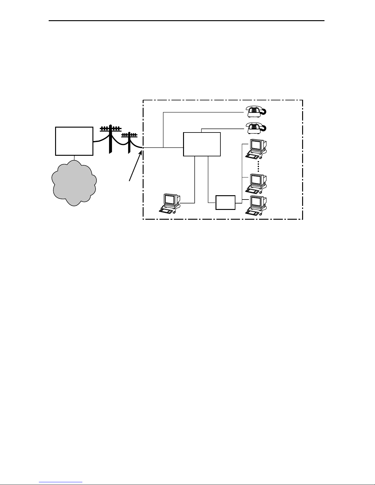
Hotwire ReachDSL System
Copper pairs run from the central office (CO) to the customer premises (CP) to create
the local loop. The local loop terminates on the customer premises at the demarcation
point.
Customer Premises (CP)
Central
Office
(CO)
Network
Service
Provider
(NSP)
Local Loop
DSL/POTS
Ethernet
Crossover
Demarcation
Point
Cable
ReachDSL
Modem
Ethernet
or
End-user
Systems
Cable
Hub
DSL – Digital Subscriber Lines
00-16867
POTS – Plain Old Telephone Service
NOTES:
In this document:
— A telephone is used to represent any equipment that plugs into a phone jack
and uses the POTS line, such as a phone, modem, or fax machine.
— End-user system is used to represe nt an y PC with an Et hernet connection and
ReachDSL-based service.
— RJ11 wall jack is used to represent either an RJ11 or an RJ14 wall jack. The
RJ14 wall jack is used for a phone with two lines.
— Service provider is used to represent any Internet Service Provider (ISP) or
remote LAN access provider.
2
Phone Filter
Depending on th e type of phone ha ndset and the quality of the home or bu siness w iring,
a phone filter is recommended to minimize background noise during a phone
conversation. An internal phone filter is included with the Hotwire 6350 ReachDSL
Modem. If additional telephones are used on the same phone line as the ReachDSL
modem, install one phone filter on each telephone.
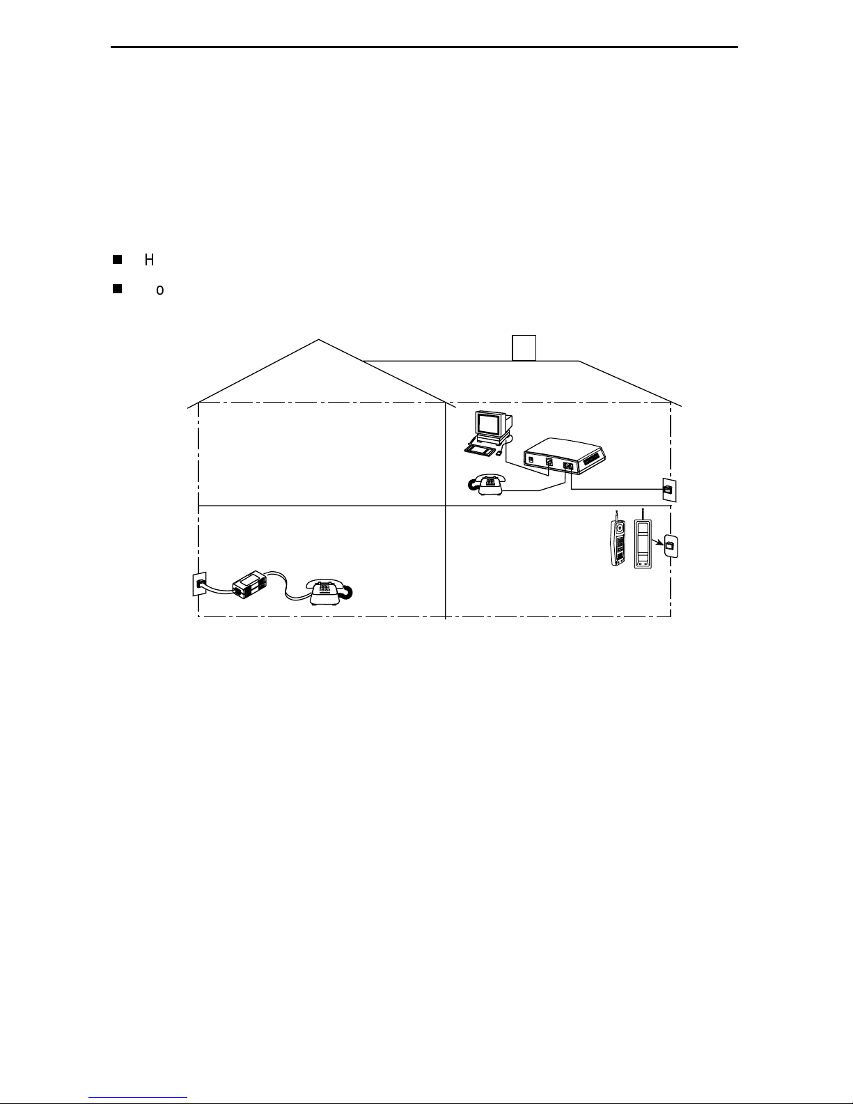
There are two Hotwire phone filters:
Hotwire 6035 Universal Phone Filter is designed for use with a tabletop phone.
Hotwire 6040 Wall Jack Phone Filter is designed for use with a wall phone.
Customer
Premises (CP)
ReachDSL
Modem
P
O
W
E
R
E
T
H
E
R
N
E
T
P
H
O
N
E
L
I
N
E
RJ11
Wall
Jack
6035
RJ11
Wall Jack
Phone Filter
6040
Wall Jack
Phone
Filter
01-16998
Product-Related Documents
To install a phone filter, refer to the appropriate document:
Document
Number Document Title
6035-A2-GN11
6040-A2-GN11
Contact your sales or service representative to order additional product documentation.
Paradyne documents are available on the World Wide Web at
Select
Library → Technical Manuals → Hotwire DSL & MVL Systems.
Hotwire 6035 Universal Phone Filter Installation Instructions
Hotwire 6040 MVL Wall Jack Phone Filter Installation Instructions
www.paradyne.com
.
3

Getting Started
Before beginning your modem’s installation, make sure that you have all the equipment
that you need.
Package Checklist
Verify that your package contains the following:
Hotwire 6350 ReachDSL Modem
❑
DSL interface cable with RJ11 connectors
❑
Power cord with power transformer
❑
Be sure to register your warranty at
www.paradyne.com/warranty
.
Wiring and Cables You Need
The following standard cables and connectors are used with this product:
Standard RJ11 (or RJ14) wall jack for the DSL cabling.
❑
Standard Ethernet 8-pin, non-keyed modular plug for a PC or workstation with an
❑
Ethernet straight-through or crossover cable.
— Refer to
cable installation details.
— Refer to
assignments.
Installing the Hotwire 6350 ReachDSL Modem
Cables & Connectors
on page 11 for DSL and Ethernet cable pin
on page 5 for Ethernet
4
Installing the Hotwire 6350 ReachDSL Modem
Place the Hotwire 6350 ReachDSL Modem on a flat surface with clearance for the rear
connectors.
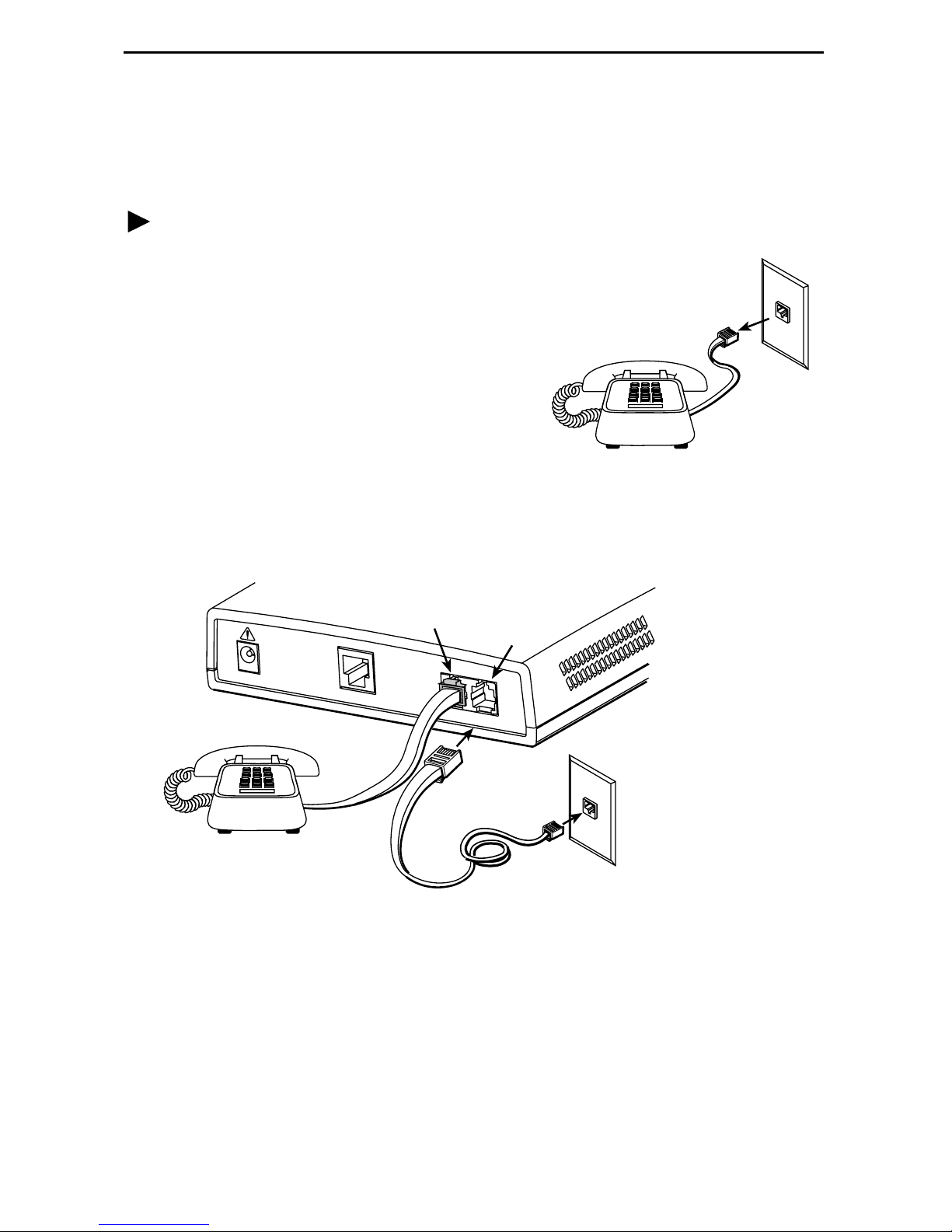
Procedure
If a telephone is connected at the RJ11
1.
wall jack where the modem will be installed,
unplug the telephone line from the wall jack.
Connect a telephone to the modem.
2.
(Optional – go to Step 3 if you are not
connecting a telephone to the ReachDSL
modem.)
RJ11
Wall Jack
Plug the exis tin g telep hon e inte rface cable
that was unplugged in Step 1 into the jack
labeled PHONE.
Use the supplied RJ11 6-pin interface cable for the ReachDSL LINE connection.
3.
Insert one end of the cable into the jack labeled LINE. Insert the other end of the
cable into the RJ11 wall jack.
PHONE
LINE
POW
ER
ETHERNET
PHONE LINE
RJ11
Wall Jack
RJ11
6-pin
Interface Cable
01-17015
01-17015a
NOTE:
If you are installing a POTS splitter with another telephone, connect the
telephone to the jack labeled PHONE, then connect the jack lab ele d LINE t o a
wall jack. Do NOT plug any cable into the POTS splitter jack labeled either
MODEM or DSL. In particular, make NO connections between a POTS splitter
and the modem.
5
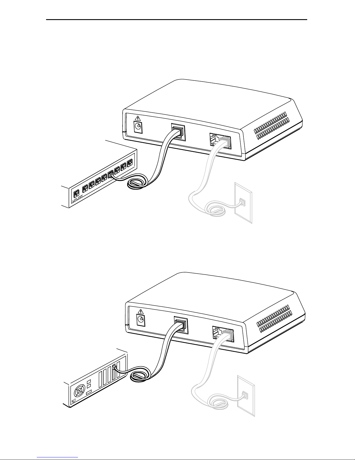
Use an 8-pin Ethernet cable for the Ethernet connec tion. Insert one end of the cable
4.
into the jack labeled ETHERNET.
— Use a straight-through cable and connect the other end to an Ethernet hub.
(To connect to a hub’s Uplink connection, use an Ethernet crossover cable).
Ethernet
Line
POWER
ETHERNET
PHONE LINE
Ethernet
8
Hub
7
4
5
6
1
2
3
Ethernet
Straight-Through
Cable
01-17008
–or–
— Use an Ethernet crossover cable and connect the other end to a PC with an
Ethernet Network Interface Card (NIC) installed.
Ethernet
Line
POWER
ETHERNET
PC with Ethernet
PHONE LINE
Network Interface
Card
Ethernet
Crossover
Cable
01-17009
6
Insert the supplied power cord’s round end into the jack labeled POWER. Plug the
5.
transformer into an AC outlet.
Power
Jack
POW
ER
ETHERNET
PHONE LINE
Transformer
or
01-17010
The ReachDSL modem hardware installation is now complete. When the power cord is
installed, the ReachDSL modem goes through a power-on self-te st.
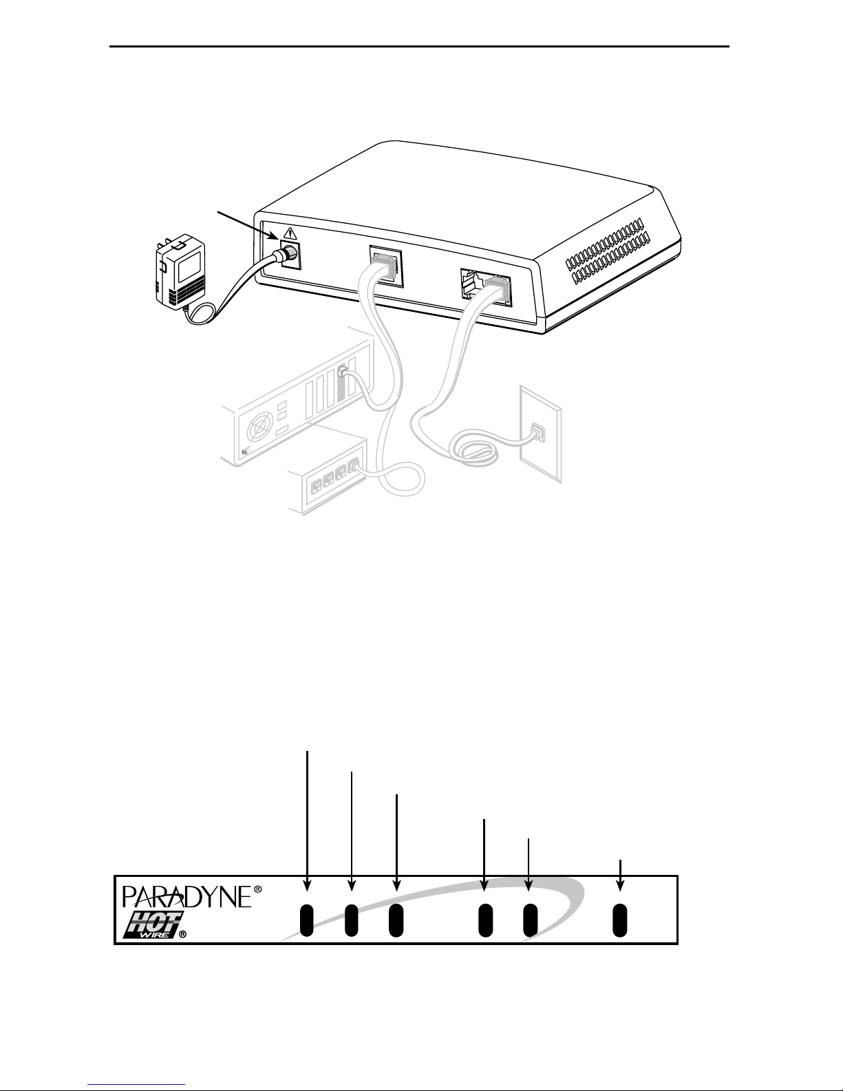
Power-On
When power is applied, the ReachDSL modem performs self-diagnostics and the PWR
LED is on. T he se lf-diag nostic s in clude s a p ow er-on s elf-tes t and all o f the L EDs turn on
for one second.
Power – green
Alarm – red
Test – yellow
DSL Line – green
Transmit/Receive – green
Ethernet Link – green
ALMPWR
TST
LINE ETHERNET
TX/RX
ReachDSL
01-17003
7

Status LEDs
All of the LEDs turn on and off du ring the pow er-on s elf-tes t. After a s uccessf ul sel f-test,
the LEDs should appear as indicated in
LED Condition Status
BOLD
in the Condition column below.
PWR
ALM
TST
LINE
TX/RX
ETHERNET
ON
OFF
ON
OFF
ON
ON
OFF
ON
OFF
ON
OFF
ReachDSL modem has power.
No active alarms.
An alarm condition exists.
No active tests.
The TST LED is on during the power-on self-test and
during a test initiated by the service provider.
The DSL link is active and ready to transmit and receive
data.
The DSL link has not been established.
Data transmission is in progress on the DSL line.
The modem is not transmitting or receiving data.
The Ethe rnet connection to the Ethernet hub or PC is
active.
No Ethernet 10BaseT device is detected.
Refer to
Troubleshooting
on page 9 for LED indications requiring action.
8
 Loading...