

Page 1

Hotwire
Document No. 6371-A2-GB20-20
®
DSL Routers
User’s Guide
May 2001
Page 2

Copyright © 2001 Paradyne Corporation.
All rights reserved.
Printed in U.S.A.
Notice
This publication is protected by federal copyright law. No part of this publication may be copied or distributed,
transmitted, tr ansc ribed, store d in a re trie v al syst em, or tr ans lated into a n y huma n or com puter l anguag e in an y form or
by any means, electronic, mechanical, magnetic, manual or otherwis e , or disclosed to third parties without the ex pre ss
written permission of Paradyne Corporation, 8545 126th Ave. N., Largo, FL 33773.
Paradyne Corporation makes no representation or warranties with respect to the contents hereof and specifically
disclaims any implied warranties of merchantability or fitness for a particular purpose. Further, Paradyne Corporation
reserves the right to revise this publication and to make changes from time to time in the contents hereof without
obligation of Paradyne Corporation to notify any person of such revision or changes.
Changes and enhancements to the product and to the information herein will be documented and issued as a new
release to this manual.
Warranty, Sales, Service, and Training Information
Contact your local sale s representativ e, se rvice representativ e, or distrib utor directly f or any hel p needed. F or additional
information concerning warranty, sales, service, repair, installation, documentation, training, distributor locations, or
Paradyne worldwide office locations, use one of the following methods:
Internet:
www.paradyne.com/warranty
Telephone:
representative.
— Within the U.S.A., call 1-800-870-2221
— Outside the U.S.A., call 1-727-530-2340
Visit the Paradyne World Wide Web s i te at
.)
Call our automated system to receive current information by fax or to speak with a company
www.paradyne.com
. (Be sure to register your warranty at
Document Feedback
We welcome your comments and suggestions about this document. Please mail them to Technical Publications,
Paradyne Corporation, 8545 126th Ave. N., Largo, FL 33773, or send e-mail to
number and title of this document in your correspondence. Please include your name and phone number if you are
willing to provide additional clarification.
userdoc@paradyne.com
. Include the
Trademarks
ACCULINK, COMSPHERE, FrameSaver, Hotwire, MVL, NextEDGE, OpenLane, and Performance Wizard are
registered trademarks of Paradyne Corporation. ReachDSL and TruePut are trademarks of Paradyne Corporation. All
other products and s ervices m en tion ed here in are the trademarks, service marks , reg is tere d trademarks, or registered
service marks of their respective owners.
May 2001 6371-A2-GB20-20
A
Page 3

Contents
About This Guide
Document Purpose and Intended Audience . . . . . . . . . . . . . . . . . . . . vii
Document Summary . . . . . . . . . . . . . . . . . . . . . . . . . . . . . . . . . . . . . . viii
Product-Related Documents . . . . . . . . . . . . . . . . . . . . . . . . . . . . . . . . ix
Document Conventions . . . . . . . . . . . . . . . . . . . . . . . . . . . . . . . . . . . . x
1 Introduction to Hotwire DSL Routers
What is a Hotwire DSL Router? . . . . . . . . . . . . . . . . . . . . . . . . . . . . . . 1-1
DSL Technologies Supported . . . . . . . . . . . . . . . . . . . . . . . . . . . . 1-1
Typical DSL Router System . . . . . . . . . . . . . . . . . . . . . . . . . . . . . . . . . 1-2
Hotwire DSL Router Features . . . . . . . . . . . . . . . . . . . . . . . . . . . . . . . 1-3
Service Subscriber. . . . . . . . . . . . . . . . . . . . . . . . . . . . . . . . . . . . . . . . 1-4
2 Accessing the DSL Router
Access Control to the DSL Router . . . . . . . . . . . . . . . . . . . . . . . . . . . . 2-1
Levels of Access . . . . . . . . . . . . . . . . . . . . . . . . . . . . . . . . . . . . . . 2-1
Changing Access Session Levels . . . . . . . . . . . . . . . . . . . . . . . . . 2-2
Local Console Access . . . . . . . . . . . . . . . . . . . . . . . . . . . . . . . . . . 2-2
Setting Up the New User's Login. . . . . . . . . . . . . . . . . . . . . . . . . . 2-3
Telnet Access . . . . . . . . . . . . . . . . . . . . . . . . . . . . . . . . . . . . . . . . 2-4
Determining the Current Access Level . . . . . . . . . . . . . . . . . . . . . 2-4
Determining the Available Commands . . . . . . . . . . . . . . . . . . . . . 2-4
Using the List Command . . . . . . . . . . . . . . . . . . . . . . . . . . . . . . . . 2-5
Changing the System Identity . . . . . . . . . . . . . . . . . . . . . . . . . . . . 2-5
Exiting from the System . . . . . . . . . . . . . . . . . . . . . . . . . . . . . . . . . . . . 2-5
Manually Logging Out . . . . . . . . . . . . . . . . . . . . . . . . . . . . . . . . . . 2-6
Automatically Logging Out. . . . . . . . . . . . . . . . . . . . . . . . . . . . . . . 2-6
6371-A2-GB20-20 May 2001
i
Page 4

Contents
3 Configuring the DSL Router
DSL Router Configuration Overview . . . . . . . . . . . . . . . . . . . . . . . . . . 3-1
The DSL Router’s Interfaces . . . . . . . . . . . . . . . . . . . . . . . . . . . . . . . . 3-1
Interface Identifiers . . . . . . . . . . . . . . . . . . . . . . . . . . . . . . . . . . . . 3-2
Service Domain IP Address Assignments. . . . . . . . . . . . . . . . . . . . . . 3-2
Numbered DSL or Ethernet Interface . . . . . . . . . . . . . . . . . . . . . . 3-3
Unnumbered DSL Interface. . . . . . . . . . . . . . . . . . . . . . . . . . . . . . 3-3
IP Routing . . . . . . . . . . . . . . . . . . . . . . . . . . . . . . . . . . . . . . . . . . . . . . 3-4
Network Considerations . . . . . . . . . . . . . . . . . . . . . . . . . . . . . . . . . . . . 3-4
Address Resolution Protocol (ARP). . . . . . . . . . . . . . . . . . . . . . . . . . . 3-5
Proxy ARP . . . . . . . . . . . . . . . . . . . . . . . . . . . . . . . . . . . . . . . . . . . . . . 3-5
Network Address Translation (NAT) . . . . . . . . . . . . . . . . . . . . . . . . . . 3-6
Basic NAT . . . . . . . . . . . . . . . . . . . . . . . . . . . . . . . . . . . . . . . . . . . 3-6
Network Address Port Translation (NAPT/PAT) . . . . . . . . . . . . . . 3-6
Simultaneous Basic NAT and NAPT . . . . . . . . . . . . . . . . . . . . . . . 3-7
IP Options Processing . . . . . . . . . . . . . . . . . . . . . . . . . . . . . . . . . . 3-7
Applications Supported by NAT. . . . . . . . . . . . . . . . . . . . . . . . . . . 3-7
Dynamic Host Configuration Protocol (DHCP) Server. . . . . . . . . . . . . 3-8
DHCP Relay Agent . . . . . . . . . . . . . . . . . . . . . . . . . . . . . . . . . . . . . . . 3-9
Security . . . . . . . . . . . . . . . . . . . . . . . . . . . . . . . . . . . . . . . . . . . . . . . . 3-10
IP Protocol Type Filtering . . . . . . . . . . . . . . . . . . . . . . . . . . . . . . . 3-10
Ethernet Type Filtering . . . . . . . . . . . . . . . . . . . . . . . . . . . . . . . . . 3-11
Land Bug/Smurf Attack Prevention . . . . . . . . . . . . . . . . . . . . . . . . 3-11
Routed vs. Bridged PDUs . . . . . . . . . . . . . . . . . . . . . . . . . . . . . . . . . . 3-12
4 DSL Router Configuration Examples
Configuration Examples . . . . . . . . . . . . . . . . . . . . . . . . . . . . . . . . . . . . 4-1
Basic Bridging Configuration Example . . . . . . . . . . . . . . . . . . . . . 4-2
Basic Routing Configuration Example . . . . . . . . . . . . . . . . . . . . . . 4-3
Basic NAT Configuration Example . . . . . . . . . . . . . . . . . . . . . . . . 4-4
NAPT Configuration Example . . . . . . . . . . . . . . . . . . . . . . . . . . . . 4-6
Simultaneous Basic NAT and NAPT Configuration Example . . . . 4-8
Unnumbered DSL Interface with Proxy ARP Configuration
Example. . . . . . . . . . . . . . . . . . . . . . . . . . . . . . . . . . . . . . . . . . . . . 4-10
DHCP Relay with Proxy ARP Configuration Example. . . . . . . . . . 4-11
DHCP Server with Basic NAT Configuration Example . . . . . . . . . 4-12
Downstream Router Configuration Example . . . . . . . . . . . . . . . . . 4-13
May 2001 6371-A2-GB20-20
ii
Page 5

5 Monitoring the DSL Router
Monitoring the Router. . . . . . . . . . . . . . . . . . . . . . . . . . . . . . . . . . . . . . 5-1
LED Status. . . . . . . . . . . . . . . . . . . . . . . . . . . . . . . . . . . . . . . . . . . . . . 5-2
Interface Status . . . . . . . . . . . . . . . . . . . . . . . . . . . . . . . . . . . . . . . . . . 5-3
Performance Statistics. . . . . . . . . . . . . . . . . . . . . . . . . . . . . . . . . . . . . 5-3
Clearing Statistics . . . . . . . . . . . . . . . . . . . . . . . . . . . . . . . . . . . . . 5-3
Reasons for Discarded Data . . . . . . . . . . . . . . . . . . . . . . . . . . . . . 5-4
6 Diagnostics and Troubleshooting
Diagnostics and Troubleshooting Overview. . . . . . . . . . . . . . . . . . . . . 6-1
Device Restart . . . . . . . . . . . . . . . . . . . . . . . . . . . . . . . . . . . . . . . . . . . 6-1
Alarms Inquiry . . . . . . . . . . . . . . . . . . . . . . . . . . . . . . . . . . . . . . . . . . . 6-1
System Log . . . . . . . . . . . . . . . . . . . . . . . . . . . . . . . . . . . . . . . . . . . . . 6-2
SYSLOG Events . . . . . . . . . . . . . . . . . . . . . . . . . . . . . . . . . . . . . . 6-4
SYSLOG Message Display . . . . . . . . . . . . . . . . . . . . . . . . . . . . . . 6-5
Ping . . . . . . . . . . . . . . . . . . . . . . . . . . . . . . . . . . . . . . . . . . . . . . . . . . . 6-5
Ping Test Results. . . . . . . . . . . . . . . . . . . . . . . . . . . . . . . . . . . . . . 6-6
TraceRoute . . . . . . . . . . . . . . . . . . . . . . . . . . . . . . . . . . . . . . . . . . . . . 6-7
TraceRoute Test Results. . . . . . . . . . . . . . . . . . . . . . . . . . . . . . . . 6-8
Contents
6371-A2-GB20-20 May 2001
iii
Page 6

Contents
A Command Line Interface
Command Line Interface Capability. . . . . . . . . . . . . . . . . . . . . . . . . . . A-1
Navigating the Router’s CLI. . . . . . . . . . . . . . . . . . . . . . . . . . . . . . A-1
Command Recall . . . . . . . . . . . . . . . . . . . . . . . . . . . . . . . . . . . . . . A-2
Syntax Conventions. . . . . . . . . . . . . . . . . . . . . . . . . . . . . . . . . . . . A-2
CLI Commands . . . . . . . . . . . . . . . . . . . . . . . . . . . . . . . . . . . . . . . . . . A-3
Configuration Commands . . . . . . . . . . . . . . . . . . . . . . . . . . . . . . . A-4
RFC 1483 Encapsulation Command. . . . . . . . . . . . . . . . . . . . . . . A-5
Ethernet Frame Format Command . . . . . . . . . . . . . . . . . . . . . . . . A-5
Interface and Service Domain IP Address Commands . . . . . . . . . A-6
IP Routing Commands. . . . . . . . . . . . . . . . . . . . . . . . . . . . . . . . . . A-7
Bridge Commands. . . . . . . . . . . . . . . . . . . . . . . . . . . . . . . . . . . . . A-8
ARP Commands . . . . . . . . . . . . . . . . . . . . . . . . . . . . . . . . . . . . . . A-9
Proxy ARP Command . . . . . . . . . . . . . . . . . . . . . . . . . . . . . . . . . . A-10
NAT Commands . . . . . . . . . . . . . . . . . . . . . . . . . . . . . . . . . . . . . . A-11
DHCP Server Commands . . . . . . . . . . . . . . . . . . . . . . . . . . . . . . . A-14
DHCP Relay Agent Commands. . . . . . . . . . . . . . . . . . . . . . . . . . . A-15
IP Packet Processing Commands. . . . . . . . . . . . . . . . . . . . . . . . . A-16
Traps Command . . . . . . . . . . . . . . . . . . . . . . . . . . . . . . . . . . . . . . A-17
Clearing Statistics Command . . . . . . . . . . . . . . . . . . . . . . . . . . . . A-17
Show Commands . . . . . . . . . . . . . . . . . . . . . . . . . . . . . . . . . . . . . A-18
B Configuration Defaults and Command Line Shortcuts
Configuration Default Settings . . . . . . . . . . . . . . . . . . . . . . . . . . . . . . . B-1
Command Line Shortcuts. . . . . . . . . . . . . . . . . . . . . . . . . . . . . . . . . . . B-3
May 2001 6371-A2-GB20-20
iv
Page 7

C Traps and MIBs
SNMP Overview. . . . . . . . . . . . . . . . . . . . . . . . . . . . . . . . . . . . . . . . . . C-1
Traps Overview . . . . . . . . . . . . . . . . . . . . . . . . . . . . . . . . . . . . . . . . . . C-1
MIBs Overview. . . . . . . . . . . . . . . . . . . . . . . . . . . . . . . . . . . . . . . . . . . C-3
Standard MIBs . . . . . . . . . . . . . . . . . . . . . . . . . . . . . . . . . . . . . . . . . . . C-3
Paradyne Enterprise MIBs. . . . . . . . . . . . . . . . . . . . . . . . . . . . . . . . . . C-11
Contents
DSL Router Traps . . . . . . . . . . . . . . . . . . . . . . . . . . . . . . . . . . . . . C-2
MIB II (RFC 1213) . . . . . . . . . . . . . . . . . . . . . . . . . . . . . . . . . . . . . C-3
System Group . . . . . . . . . . . . . . . . . . . . . . . . . . . . . . . . . . . . . . . . C-4
Interfaces Group (RFC 1573) . . . . . . . . . . . . . . . . . . . . . . . . . . . . C-5
Extension to Interfaces Table (RFC 1573) . . . . . . . . . . . . . . . . . . C-7
IP Group (RFC 1213). . . . . . . . . . . . . . . . . . . . . . . . . . . . . . . . . . . C-8
IP CIDR Route Group (RFC 2096) . . . . . . . . . . . . . . . . . . . . . . . . C-9
Transmission Group . . . . . . . . . . . . . . . . . . . . . . . . . . . . . . . . . . . C-10
SNMP Group . . . . . . . . . . . . . . . . . . . . . . . . . . . . . . . . . . . . . . . . . C-10
Ethernet-Like MIB (RFC 2665) . . . . . . . . . . . . . . . . . . . . . . . . . . . C-11
Device Control MIB . . . . . . . . . . . . . . . . . . . . . . . . . . . . . . . . . . . . C-12
Device Diagnostics MIB. . . . . . . . . . . . . . . . . . . . . . . . . . . . . . . . . C-13
Health and Status MIB. . . . . . . . . . . . . . . . . . . . . . . . . . . . . . . . . . C-16
Configuration MIB . . . . . . . . . . . . . . . . . . . . . . . . . . . . . . . . . . . . . C-17
Interface Configuration MIB. . . . . . . . . . . . . . . . . . . . . . . . . . . . . . C-18
ARP MIB . . . . . . . . . . . . . . . . . . . . . . . . . . . . . . . . . . . . . . . . . . . . C-18
NAT MIB . . . . . . . . . . . . . . . . . . . . . . . . . . . . . . . . . . . . . . . . . . . . C-18
DHCP MIB. . . . . . . . . . . . . . . . . . . . . . . . . . . . . . . . . . . . . . . . . . . C-19
DSL Endpoint MIB . . . . . . . . . . . . . . . . . . . . . . . . . . . . . . . . . . . . . C-20
SYSLOG MIB. . . . . . . . . . . . . . . . . . . . . . . . . . . . . . . . . . . . . . . . . C-20
Interface Configuration MIB. . . . . . . . . . . . . . . . . . . . . . . . . . . . . . C-20
D DSL Router Terminal Emulation
DSL Router Terminal Emulation . . . . . . . . . . . . . . . . . . . . . . . . . . . . . D-1
Accessing the List Command Output . . . . . . . . . . . . . . . . . . . . . . D-1
Terminal Emulation Programs. . . . . . . . . . . . . . . . . . . . . . . . . . . . D-2
Index
6371-A2-GB20-20 May 2001
v
Page 8

Contents
May 2001 6371-A2-GB20-20
vi
Page 9

About This Guide
Document Purpose and Intended Audience
This guide describes how to configure and operate Hotwire DSL routers. It
addresses the following models:
Hotwire 6301/6302 IDSL Router
Hotwire 6341/6342 Symmetric DSL Router
Hotwire 6351 ReachDSL Router
Hotwire 6371 RADSL Router
This document is intended for administrators and operators who maintain the
endpoints at customer premises. A basic understanding of internetworking
protocols and their features is assumed. Specifically, you should have familiarity
with the following internetworking concepts:
TCP/IP applications
IP and subnet addressing
IP routing
Bridging
It is also assumed that you have already installed a Hotwire DSL Router. If not,
refer to
Product-Related Documents
for installation documents.
6371-A2-GB20-20 May 2001
vii
Page 10

About This Guide
Document Summary
Section Description
Chapter 1,
Routers
Chapter 2,
Chapter 3,
Chapter 4,
Examples
Chapter 5,
Chapter 6,
Troubleshooting
Appendix A,
Appendix B,
and Command Line Shortcuts
Appendix C,
Introduction to Hotw ire DSL
Accessing the DSL Router
Configuring the DSL Router
DSL Router Configuration
Monitoring the DSL Router
Diagnostics and
Command Line Interface
Configuration Defaults
Traps and MIBs
Provides an overview of the Hotwire DSL
Routers.
Describes the Hotwire DSL Routers access
control and provide s instructions on ho w to log in
and log out of the system.
Describes the DSL router interfaces, Domain
Types, IP Routing, and network considerations.
Presents several common DSL router
configuration examples.
Describes operator programs that monitor the
Hotwire system.
Describes common Hotwire operational
problems and solutions. Contains SysLog
information.
Provides explanation of the DSL router’s
Command Line Interface and command syntax
with examples.
Provides a list of all configuration options with
factory default settings and a list of al l c om ma nd
line shortcuts with the abbre viated comma nd line
input.
Summarizes the MIBs and SNMP traps
supported by the DSL routers.
Appendix D,
Emulation
Index
DSL Router Terminal
Provides configuration setup procedures for two
common text file programs.
Lists key terms, acronyms, concepts, and
sections in alphabetical order.
A master glossary of terms and acronyms used in Paradyne documents is
available on the Web at
Manuals
→
Technical Glossary.
www.paradyne.com
. Select
Library → Technical
May 2001 6371-A2-GB20-20
viii
Page 11

Product-Related Documents
Docume n t Number Docume n t Title
About This Guide
5030-A2-GN10
5038-A2-GN10
6050-A2-GZ40
6301-A2-GN10
6341-A2-GN10
6351-A2-GN10
6371-A2-GN10
8000-A2-GB22
8000-A2-GB26
Hotwire 5030 POTS Splitter Customer Premises
Installation Instructions
Hotwire 5038 Distributed POTS Splitter Customer
Premises Installation Instructions
Hotwire Central Office Universal POTS Splitter, Models
6050 and 7020, Installation Instructions
Hotwire 6301/6302 IDSL Routers Installation
Instructions
Hotwire 6341/6342 SDSL Routers Installation
Instructions
Hotwire 6351 ReachDSL Router Installation Instructions
Hotwire 6371 RADSL Router Installation Instructions
Hotwire Management Communications Controller
(MCC) Card, IP Conservative, User's Guide
Hotwire MVL, ReachDSL/MVL, RADSL, IDSL, and
SDSL Cards, Models 8310, 8312/8314,
8510/8373/8374, 8303/8304, and 8343/8344, User's
Guide
Contact your sales or service representative to order additional product
documentation.
Paradyne documents are also available on the World Wide Web at
www.paradyne.com
Hotwire DSL and MVL Systems
. Select
Library → Technical Manuals →
.
6371-A2-GB20-20 May 2001
ix
Page 12

About This Guide
Document Conventions
The following conventions are used throughout this document.
Convention Translation
[ ]
{ }
|
Italics
Bold
x.x.x.x
xx:xx:xx:xx:xx:xx
Square brackets represent an optional element.
Braces represent a required entry.
Vertical bar separates mutually exclusive elements.
Entry is a variable to be supplied by the operator.
Enter (type) as shown.
32-bit IP address and mask information where x is an
8-bit weighted decimal notation.
MAC address information where x is a hexadecimal
notation.
May 2001 6371-A2-GB20-20
x
Page 13

Introducti on to Hotwire DSL Routers
What is a Hotwire DSL Router?
The Hotwire® DSL (Digital Subscriber Line) Router operates as a bridge and IP
router connecting a DSL link to an Ethernet network. This system provides
high-speed access to the Internet or a corporate network over a traditional
twisted-pair copper telephone line to the end user.
DSL Technologies Supported
Paradyne’s Hotwire DSL network supports the following types of technologies:
1
Hotwire IDSL (ISDN DSL) products provide IDSL multirate symmetric packet
transport and can operate over a connection with an ISDN repeater or digital
facilities. Data rates of 64 Kbps, 128 Kbps, or 144 Kbps can be configured.
Hotwire SDSL (Symmetric DSL) packet-based products provide high-speed
symmetric DSL services with bandwidth for business applications. These
products are configurable from 144 Kbps up to 2.3 Mbps. This gives service
providers the opportunity to sell multiple services with a single product.
Hotwire ReachDSL™ packet-based products provide high-speed Internet or
corporate LAN access over traditional twisted-pair copper telephone wiring,
regardless of line conditions (poor quality loops, long loops, or bad wiring at
customer premises), for guaranteed service delivery up to 18,000 feet. These
products are configurable from 128 Kbps up to 960 Kbps Mbps and give
service providers the opportunity to sell multiple services using a single
product.
Hotwire RADSL (Rate Adaptive DSL) products are applicable for both
asymmetric and symmetric applications. The 1 Mbps symmetric operation is
ideal for traditional business applications while the 7 Mbps downstream with
1.1 Mbps upstream asymmetric operation provides added bandwidth for
corporate Internet access. RADSL products can also save line costs by
optionally supporting simultaneous data and voice over the same line.
6371-A2-GB20-20 May 2001
1-1
Page 14
1. Introduction to Hotwire DSL Routers
Typical DSL Router System
DSL is a local loop technology that uses standard twisted-pair copper wire to
support high-speed access over a single pair of twisted copper wires. DSL
applications are point-to-point, requiring DSL devices at central and end-user
sites.
Hotwire DSL routers interoperate with the following types of Hotwire DSL line
cards, at the DSLAM (Digital Subscriber Line Access Multiplexer) or GranDSLAM
chassis, to deliver applications at high speeds, supporting packet services over a
DSL link:
Hotwire 8303 or 8304 IDSL Cards interoperate with two Hotwire IDSL Routers:
— Hotwire 6301 IDSL Router with one Ethernet port
— Hotwire 6302 IDSL Router with a 4-port Ethernet hub
Hotwire 8343 or 8344 SDSL Cards interoperate with two Hotwire Symmetric
DSL Routers:
— Hotwire 6341 SDSL Router with one Ethernet port
— Hotwire 6342 SDSL Router with a 4-port Ethernet hub
Hotwire 8312 or 8314 ReachDSL Cards interoperate with the Hotwire 6351
ReachDSL Router with one Ethernet port
Hotwire 8510, 8373, and 8374 RADSL Cards interoperate with the Hotwire
6371 RADSL Router with one Ethernet port
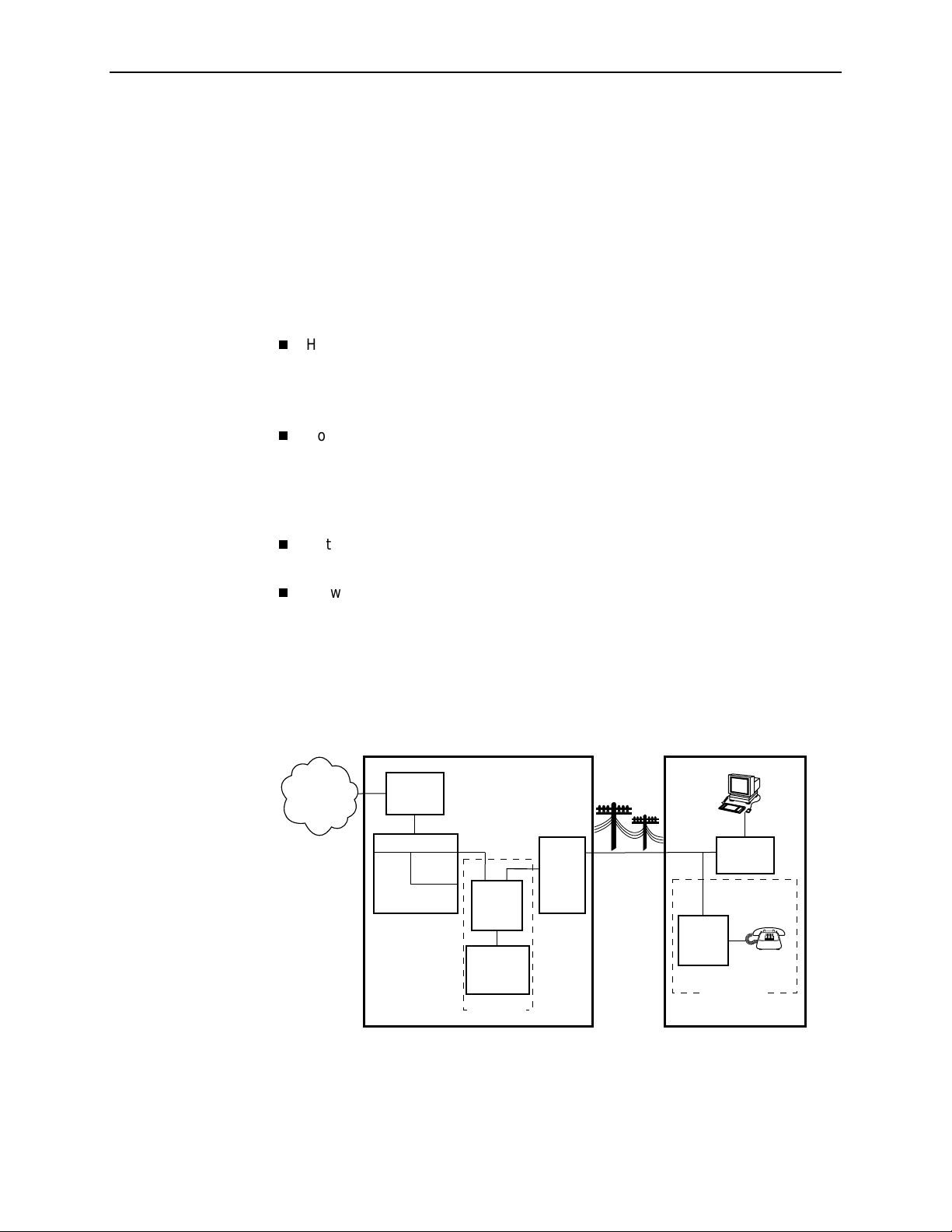
The following illustration shows a typical Hotwire system with a Hotwire DSL
Router. All Hotwire DSL routers transport data. The Hotwire 6371 RADSL Router
can transport data and POTS simultaneously.
Customer Premises (CP)
Data
Interface
SN
POTS
Voice
Interface
CP
POTS
Splitter
Optional
Network
Service
Provider
Central Office (CO)
Hotwire
IPC
ATM
SCM
DSL
CARD
GranDSLAM
CO
POTS
Splitter
Switched
Network
Optional
MDF
POTS/DSL
Legend: DSL – Digital Subscriber Line IPC –Interworking Packet Concentrator
May 2001 6371-A2-GB20-20
1-2
MDF – Main Distribution Frame POTS – Plain Old Telephone Service
SN – Service Node
01-16968
Page 15

Hotwire DSL Router Features
The Hotwire DSL routers contain the following features.
IP routing with
— NAT (Network Address Translation)
— NAPT (Network Address Port Translation), also called PAT (Port Address
Translation)
— Simultaneous Basic NAT (for several fixed servers) and NAPT (on the rest
of the PCs on the LAN)
— DHCP Server (Dynamic Host Configuration Protocol) and DHCP Relay
Agent
— A full set of IP filters, two per DSL card (one for upstream and one for
downstream traffic), with up to 33 rules per filter
— SNMP Set/Get capabil it y
Three Configurable Modes of Operation.
operation:
:
1. Introduction to Hotwire DSL Routers
Supports the following modes of
— IP routing only
— IP routing, and bridging of all other protocols (using VNET mode)
— Bridging all protocols (using VNET mode)
Protocol Filters.
Provides the ability to:
— Filter MAC frames when bridging
— Configure two Ethertype filters via the Hotwire DSL card, one for upstream
and one for downstream traffic, with up to 16 filter rules per filter
— Compare the Ethertype in frames to a particular value, or configured set of
values, to perform filtering
— Support ICMP (Internet Control Management Protocol) filters for firewalls
via the Hotwire DSL card, based on the ICMP message type, to selectively
discard some ICMP message types while forwarding others
High-speed Internet or intranet access.
Diagnostics.
Provides the capability to diagnose device and network
problems and perform tests.
Device and Test Monitoring.
Provides the capability of tracking and
evaluating the unit’s operation.
Remote Firmware Download.
Provides easy setup and activation of
firmware upgrades from a remote location.
Security.
Provides multiple levels of security, which prevents unauthorized
access to the DSL router.
6371-A2-GB20-20 May 2001
1-3
Page 16

1. Introduction to Hotwire DSL Routers
Console Terminal Interface.
— Configuring and managing the DSL router
— Terminal access
Management from an NMS using SNMP.
Service Subscriber
The Service Subscriber is the user (or set of users) that has contracted to receive
networking services (e.g., Internet access, remote LAN access) for the end-user
system from an NSP (Network Service Provider). Service subscribers may be:
Residential users connected to public network services (e.g., the Internet)
Work-at-home users connected to their corporate intranet LAN
Commercial users at corporate locations (e.g., branch offices) connected to
other corporate locations or connected to public network services
Provides an interface for:
A Hotwire DSL Router must be installed at the customer premises to provide the
end user with access to any of the above services.
NOTE:
If you would like more information on DSL-based services, applications, and
network deployment, refer to Paradyne’s
may be downloaded or ordered through Paradyne’s World Wide Web site at
www.paradyne.com/library
.
The DSL Sourcebook.
The book
May 2001 6371-A2-GB20-20
1-4
Page 17

Accessing the DSL Router
Access Control to the DSL Router
The Hotwire DSL Router can be managed from an NMS using SNMP or from the
Command Line Interface (CLI). There are two methods to access the command
line interface:
Local access at the DSL router through the Console port, or
Access by a Telnet session (controlled through the management interface at
the Hotwire chassis).
2
Levels of Access
When a local console connection is first established, a login prompt appears. The
Hotwire DSL Router accepts only one login session at a time. It is configured at
the factory with a default login ID and password. Howev er , to provide login security
to the DSL system or set up a new user’s log in, r efer to
Login
on page 2-3.
There is one login ID and two levels of privileges on the Hotwire DSL system.
Your user account can be configured with one user name and different
passwords for:
Administrator
— Administrator, non-configuration mode: Provides read-only capabilities.
This is the same level of access as Operator.
— Administrator, configuration mode: Provides complete write access to the
DSL router. However, MIB sets are done from the NMS vs. the command
line.
Operator
with no modification permission and no access to management functions.
Refer to Appendix A,
command line entr y.
. The Administrator has two levels of access to the DSL router.
. The Operator has read-only access to display device information
Command Line Interface
, for access level details for each
Setting Up the New User's
6371-A2-GB20-20 May 2001
2-1
Page 18

2. Accessing the DSL Router
Changing Access Session Levels
To change the Administrator access level, enter:
admin enable
This command provides Administrator access privileges. The router responds
with a prompt to enter the password for Administrator access.
To end the Administrator access level, enter:
admin disable
This command ends the Administrator session. No password is needed.
Local Console Access
Entering
exit
has the same result. Refer to
Exiting from the System
on
page 2-5 for further details on ending a session.
The Operator and Administrator have the same Login ID, but with different
passwords for their access level.
To determine the access level for a session, refer to
Access Level
on page 2-4.
Determining the Curre nt
The DSL router ships with the local console enabled. After login, the local console
can be disabled.
To disable with the local console, type:
console disable
save
exit
Press Enter after each command that you type.
Entering
console disable
results in NO local access to the DSL router. If
you attempt to log in, you will receive an error message.
After saving this change and ending the session, there is no local access
through the console port. Any access must be through a Telnet session or
the NMS.
To determine via a Telnet session whether a console is enabled, enter:
show console
One of the following messages is returned:
console enabled
—
– Command line management is available at the
console.
console disabled
—
– No command line management is available at the
console.
May 2001 6371-A2-GB20-20
2-2
Page 19

Setting Up the New User's Login
A login prompt appears when the local console connection is first established.
When the login prompt appears, a locally connected console defaults to Console
Enabled, with Operator access.
Procedure
To access the router’s CLI for the first-time:
2. Accessing the DSL Router
1. At the initial
Login>
prompt, type the default login ID
paradyne
and press
Enter.
2. At the
Password>
prompt (for Operator), type the default password
and press Enter. The login ID and password are validated together when a
login is entered.
3. At the system identity of
CUSTOMER>
prompt, type
admin enable
and press
Enter.
abc123
Password>
and press Enter.
prompt (for Administrator), type the default password
System identity changes to the Administrator display mode of
configure terminal
and press Enter.
CUSTOMER#>
4. At the
5. Type
System identity changes to the Administrator configuration mode of
CUSTOMER - CONFIG#>
.
6. To change or add a new login ID, enter text to replace the default of
paradyne
:
name
your new login ID
NOTE:
Login ID and password are NOT case-sensitive.
abc123
.
7. Enter a new password and specify the level:
password
Example: Type
level password
password operator 238clrd3
Both the login ID and password are 1–31 printable alphanumeric ASCII
characters, in the ASCII hex range of 0x21–0x7E. No spaces are allowed.
The following table lists invalid characters.
Invalid Characters Value ASCII Hex Translation
#
$
%
&
6371-A2-GB20-20 May 2001
Number sign 0x23
Dollar sig n 0x24
Percentage 0x25
Ampersand 0x26
and press Enter.
2-3
Page 20

2. Accessing the DSL Router
8. At the prompt, enter the new Administrator-level password to replace
password admin
save
NOTE:
Any input during an Administrator configuration session must be saved
while still in configuration mode.
If denied access during a T elnet session, the session stops and an error is logged.
If accessing the router locally and a Telnet session is active, you receive a
Local console disabled by conflict
Telnet Access
Telnet access defaults to Administrator level. If the login is at the Operator level,
then Operator level access is available. Telnet access is always enabled.
Determining the Current Access Level
The command line prompt displays the access level. The factory default for
System identity is
replace
CUSTOMER
new password
CUSTOMER>
. You can set your own system identity name to
. See the examples below.
message.
abc123
:
If the prompt format
appears as . . .
CUSTOMER> PARADYNE> Operator, display mode
CUSTOMER #> PARADYNE #> Administrator, display
CUSTOMER – CONFIG#> PARADYNE – CONFIG#> Administrator,
Determining the Available Commands
To determine the commands available at the current login access level, enter any
of the following:
help
?
(question mark)
the command, without any parameters
Or, if a System identity of
PARADYNE is entered, the
prompt displays . . .
Then the DSL router
access level is . . .
mode
configuration mode
May 2001 6371-A2-GB20-20
2-4
Page 21

Using the List Command
The list command displays a sequence of commands in the form of ASCII strings
that would have the effect of setting all configuration settings to the current values.
(The two passwords are not output.)
To determine the commands available, enter Administrator configuration mode
and type either:
list
Displays the output in on-screen page mode. In on-screen page mode, the
user interface displays 23 lines of information. When the 24th line is reached,
More...
list config
Displays the output in scroll mode as a text file. Scroll mode captures and
displays all command strings in a text file for use with a terminal emulation
program. Refer to Appendix D,
Changing the System Identity
2. Accessing the DSL Router
appears. Pressing any key displays the next page.
DSL Router Terminal Emulation.
The System identity is the same as the MIB entry of sysName. The sysContact
and sysLocation MIB entries are not displayed.
Procedure
To change System identity from the factory default of
1. Log in and enter ADMIN-configuration mode.
2. At the
CUSTOMER-CONFIG#>
(no spaces allowed) and press Enter. Then type
system identity
For example:
system identity PARADYNE
save
In this example, after saving the entry and ending configuration mode, the
System identity will display:
PARADYNE#>
Refer to
Exiting from the System
prompt, type the new System identity
new system identity
to end configuration mode.
CUSTOMER>
save
and press Enter.
:
Exiting from the System
You can manually log out of the system, or let the system automatically log you
out. The DSL router will log you out immediately if you disconnect the Console
cable. Any unsaved configuration input will be lost.
6371-A2-GB20-20 May 2001
2-5
Page 22

2. Accessing the DSL Router
Manually Logging Out
To log out, there are two commands:
logout
and
exit
.
Procedure
To log out of a CLI or Telnet session:
1. At the > prompt, type
logout
and press Enter.
2. The system ends the session immediately. Any configuration updates must
be saved before exiting or the updates will be lost.
Procedure
To exit the DSL router’s current access level:
1. At the > prompt, type
configuration changes, you will be prompted to save changes before exiting.
2. The
exit
command has the following effect:
If accessing the DSL router . . . Then . . .
At the Local console and logged in at
the Administrator level, configuration
mode
exit
and press Enter. If there are any unsaved
You are placed at the Operator level. Any
configuration updates must be saved or
they will be lost.
At the Local console and logged in at
the Admini strator level,
non-configuration mode
At the Local console and logged in at
the Operator level
Via a Telnet session and logged in at
any access level
Automatically Logging Out
The DSL router has an automatic timeout feature that logs you out of the system
after five minutes of inactivity. Unsaved configuration input is lost.
To log back in, press Enter at the console to display the
default for the
{enable | disable}
When
Enabled, the system inactivity timer is enabled.
Disabled, the system inactivity timer is disabled.
autologout
autologout
command is enable (appears as
in command line syntax).
is:
You are placed at the Operator level.
exit
The
the Logout command.
Entering either of the following immediately
ends the Telnet session:
command responds exactly like
exit
Ctrl + ]
(Control and right bracket keys)
Login>
prompt. The
autologout
May 2001 6371-A2-GB20-20
2-6
Page 23

Configuring the DSL Router
DSL Router Configuration Overview
Hotwire DSL Routers support various customer premises distribution networks
that contain IP forwarding devices or routers, as well as locally attached hosts
or subnets. The Hotwire DSL Router’s IP Routing Table contains IP address and
subnet mask information.
The DSL router supports Internet Protocol, as specified in RFC 791, and Internet
Control Message Protocol (ICMP), as specified in RFCs 792 and 950. It acts as a
router (or gateway), as defined in RFC 791. It also acts as a bridge, bridging all
traffic in the service domain, or routing IP traffic and bridging all other traffic in the
service domain, without affecting traffic in the management domain.
3
For more information on supported RFCs, refer to
The DSL Router’s Interfaces
Hotwire DSL Routers have two interfaces, the DSL interface and the Ethernet
interface.
DSL Interface
The router’s interface type is determined by its model number:
— Models 6301 and 6302 are Hotwire IDSL Routers.
— Models 6341 and 6342 are Hotwire SDSL Routers.
— Model 6351 is the Hotwire ReachDSL Router.
— Model 6371 is the Hotwire RADSL Router.
The DSL interface has a unique MAC address, assigned before the router is
shipped.
Appendix C, Traps and MIBs.
6371-A2-GB20-20 May 2001
3-1
Page 24

3. Configuring the DSL Router
Ethernet Interface
— The Ethernet interface is a 10/100BaseT interface that automatically
negotiates the rate to be used, 10 Mb or 100 Mb. If all Ethernet-attached
devices are capable of operating at 100 Mb, the router defaults to 100 Mb.
Otherwise, it operates at 10 M b.
— The interface can be configured for either DIX or IEEE 802.3 frame format.
When configured to use IEEE 802.3 format, SNAP encapsulation is used,
as specified in RFC 1042.
— The interface has a unique MAC address, assigned before the router is
shipped.
— Hotwire 6302 IDSL and 6342 SDSL Routers have a hub configuration
(separate pins for input and output) with four Ethernet connectors. The
hub acts as a bit-level repeater, with the four Ethernet interfaces logically
appearing as one Ethernet communications interface with a single
collision domain.
— In router mode, the router only accepts transmissions on the Ethernet
interface with the interface’s MAC address, or a broadcast or multicast
MAC address.
— In bridge mode, the router accepts all transmissions.
setting.
Interface Identifiers
The following conventions are used for naming router interfaces:
dsl1
(or d0) – Identifier for the DSL interface.
eth1
(or e0) – Identifier for the Ethernet interface.
With exception to primary status, an interface cannot be deleted or changed as
long as there is a declared route that uses the interface.
Service Domain IP Address Assignments
Hotwire DSL Routers support multiple service domains.
Service domains are defined by the configured network addresses and subnet
masks using the CLI.
Up to four service domain IP addresses and subnet masks can be assigned to
each DSL (
dsl1
) or Ethernet (
eth1
This is the default
) interface.
When a numbered interface is designated as the primary interface, that interface’s
IP address is used as the Router ID. If no interface is designated as the primary
interface, the last numbered interface that was created becomes the Router ID.
May 2001 6371-A2-GB20-20
3-2
Page 25

Numbered DSL or Ethernet Interface
In this scenario, the hosts attached to the DSL router’s Ethernet interface are on a
different logical network than the core router. The DSL router is the next hop router
for the hosts. The DSL router’s upstream next hop router is the core router.
Simplified Network Topology
3. Configuring the DSL Router
Core
Router
Hosts can be assigned IP addresses on the network attached to the DSL router’s
Ethernet interface, either statically or dynamically using DHCP. The upstream next
hop router is assigned an address on a different logical network than the hosts.
To configure the ro uter’s interfaces using this scenario, you must:
Enable routing on the DSL router.
Assign an IP address to the Ethernet interface, eth1.
Assign an IP address to the DSL interface, dsl1.
Assign an upstream next hop router.
Unnumbered DSL Interface
In this LAN extension application scenario, hosts connected to a corporate
network for virtual office connections or telecommuters want to look like they are
on the same network as the core router. The core router is the next hop router
for the hosts and is on the same logical network as the hosts. This is not the
same as enabling Bridging mode.
WAN
DSL
Router
Host
(End Users)
99-16609
To configure the ro uter’s interfaces for this scenario, you must:
Enable routing on the DSL router.
Assign an IP address to Ethernet interface (eth1).
Specify the DSL interface (dsl1) as unnumbered.
Assign an upstream next hop router.
Enable Proxy ARP for both the eth1 and dsl1 interfaces.
6371-A2-GB20-20 May 2001
3-3
Page 26

3. Configuring the DSL Router
IP Routing
Hotwire DSL Routers use destination-based routing for downstream traffic. An IP
Routing Table is maintained to specify how IP datagrams are forwarded
downstream. The DSL Router is capable of supporting static routes configured by
the user. This table can be viewed by both Operator and Administrator access
levels.
The DSL router uses source-based forwarding for upstream traffic to ensure that
packets are forwarded to the upstream router specified for the configured service
domain.
Refer to Chapter 4,
Network Considerations
The routers can be configured to function in a variety of network environments.
The following sections provide descriptions of some of the router’s features:
Address Resolution Protocol (ARP)
Proxy ARP
Network Address Translation (NAT)
Basic NAT
—
Network Address Port Translation (NAPT/PAT)
—
IP Options Processing
—
Simultaneous Basic NAT and NAPT
—
Dynamic Host Configuration Protocol (DHCP) Server
DHCP Relay Agent
Security
IP Protocol Type Filtering
—
DSL Router Configuration Examples,
on page 3-5
on page 3-9
on page 3-10
for further details.
on page 3-5
on page 3-6
on page 3-8
Ethernet Type Filtering
—
Land Bug/Smurf Attack Prevention
—
Routed vs. Bridged PDUs
May 2001 6371-A2-GB20-20
3-4
on page 3-12
Page 27

Address Resolution Protocol (ARP)
Address Resolution Protocol, as specified in RFC 826, is supported in the router.
Up to 265 ARP Tab le entries are supported, and a timeout period for complete and
incomplete ARP Table entries can be configured.
ARP requests and responses are not processed on the DSL interface when the
interface is configured to support RFC 1483 PDU routing (Standard mode). Refer
Routed vs. Bridged PDUs
to
Operating mode (Standard or VNET) can be changed without reconfiguration of
the router. Static ARP entries can be configured, regardless of the current
operating mode. If static ARP entries are configured, they remain in the database
and can be displayed using the
Using CLI commands, you can:
Create up to 64 static ARP Table entries.
Display the ARP Table.
Delete ARP Table entries.
on page 3-12 for more information.
show arp
3. Configuring the DSL Router
CLI command.
Proxy ARP
Display and delete automatically added ARP Tab le entries made by the DHCP
server and relay functions. Refer to
(DHCP) Server
The DSL router supports Proxy ARP. Proxy ARP responses are based on the
contents of the IP Routing Table for service domain traffic. The table must have
entry information that indicates what hosts can be reached on the Ethernet
interface, including hosts for which the router will not forward packets because of
IP filters. For additonal information on filtering, see
page 3-10.
Proxy ARP is not available on the DSL interface when the router is configured to
support RFC 1483 PDU routing. See
more information.
If an ARP request is received on one interface, and the requested IP address can
be reached on the other interface, the router responds with its own MAC address.
Using CLI commands, you can enable and disable Proxy ARP for each interface.
on page 3-8.
Dynamic Host Configuration Protocol
IP Protocol Type Filtering
Routed vs. Bridged PDUs
on page 3-12 for
on
NOTE:
When Basic NA T is enabled, the DSL interface (dsl1) must have Proxy ARP
enabled when the dsl1 interface address is part of the Basic NAT global IP
network address.
6371-A2-GB20-20 May 2001
3-5
Page 28

3. Configuring the DSL Router
Network Address Translation (NAT)
The DSL router provides NAT, as described in RFC 1631, IP Network Address
Translator (NAT).
access the external (public or global) network using either a block of public IP
addresses (Basic NAT) or a single IP address (NAPT). Static mapping enables
access to selected local hosts from outside using these external IP addresses.
NAT is used when a private network’s internal IP addresses cannot be used
outside the private network. IP addresses may be restricted for privacy reasons, or
they may not be valid public IP addresses.
Simultaneous Basic NAT and Network Address Port Translation (NAPT) are
supported. Refer to
information.
Basic NAT
Basic NAT allows hosts in a private network to transparently access the external
network by using a block of public addresses. Static mapping enables access to
selected local hosts from the outside. Basic NAT is often used in a large
organization with a large network that is set up for internal use, with the need for
occasional external access.
NAT allows hosts in a private (local) network to transparently
Simultaneous Basic NAT and NAPT
on page 3-7 for additional
Basic NAT provides a one-to-one mapping by translating a range of assigned
public IP addresses to a similar-sized pool of private addresses (typically from the
x.x.x
10.
host appears to have an unique IP address.
address space). Each local host currently communicating with a external
IP addresses
A total of 256 IP addresses can be allocated for use with Basic NAT. Two IP
addresses are reserved, and 254 IP addresses are available for use. Up to
64 static mappings can be configured.
Network Address Port Translation (NAPT/PAT)
NAPT allows multiple clients in a local network to simultaneously access remote
networks using a single IP address. This benefits telecommuters and SOHO
(Small Office/Home Office) users that have multiple clients in an office running
TCP/UDP applications. NAPT is sometimes referred to as PAT (Port Address
Translation).
NAPT provides a many-to-one mapping and uses one public address to interface
numerous private users to an external network. All hosts on the global side view
all hosts on the local side as one Internet host. The local hosts continue to use
their corporate or private addresses. When the hosts are communicating with
each other, the translation is based on the IP address and the protocol port
numbers used by TCP/IP applications.
May 2001 6371-A2-GB20-20
3-6
Page 29

Simultaneous Basic NAT and NAPT
Simultaneous Basic NAT and NAPT (or PAT) are supported. In this mode, the
servers (private IP addresses) using Basic NAT are configured and the devices
(private IP addresses) using NAPT are optionally configured (static mappings). If
not configured, the remaining private IP addresses default to NAPT.
Enabling Basic NAT does not disable NAPT. When both Basic NAT and NAPT are
enabled, Proxy ARP can also be enabled, although it is only used for Basic NAT.
IP Options Processing
Basic NA T and NAPT functions handle and process the IP datagrams, with options
set as described below. No command is available to set IP options.
The router does not process (and drops) any IP datagrams with the following IP
options:
Loose source and record route (type 131)
Strict source and record route (type 133)
3. Configuring the DSL Router
Security (type 130)
Stream ID (type 136)
The router does process IP datagrams with the following IP options, but does not
provide its IP address or timestamp information in the response message:
Record route (type 7)
Timestamp (type 68)
Applications Supported by NAT
The DSL routers support the following applications and protocols:
FTP
HTTP
Ping
RealPlayer
Telnet
TFTP
6371-A2-GB20-20 May 2001
3-7
Page 30

3. Configuring the DSL Router
Dynamic Host Configuration Protocol (DHCP) Server
The router provides a DHCP Server feature, as specified in RFC 2131, Dynamic
Host Configuration Protocol, and RFC 2132, DHCP Option and BOOTP Vendor
Extensions. DHCP is the protocol used for automatic IP address assignment.
DHCP setup considerations:
The range of IP addresses to be used by the DHCP server must be
configured. The maximum number of clients is 256.
The DHCP server is not activated until one IP address and subnet mask are
assigned to the Ethernet interface and routing is enabled.
The DHCP server must be enabled, and the DHCP server and DHCP relay
functions cannot be enabled at the same time.
When the DHCP IP address range is changed, all binding entries,
automatically added routes, and ARP Table entries for the clients configured
with the old address range are removed.
When the DHCP Server is enabled, there can be only one IP address
configured for the service domain (Ethernet interface).
The IP address for the next hop router provided to the hosts in the DHCP reply
must be configured.
The subnet mask can be configured along with the IP address range
(optional).
The DHCP server domain name can be configured (optional).
The Domain Name Server (DNS) IP address can be configured (optional).
A minimum and maximum lease time setting can be configured.
For additional information, refer to Chapter 4,
DSL Router Configuration
Examples.
May 2001 6371-A2-GB20-20
3-8
Page 31

DHCP Relay Agent
The router provides the capability of serving as a DHCP Relay Agent, as specified
in RFC 2131, Dynamic Host Configuration Protocol. The router provides the
capability to enable and disable the DHCP Relay Agent and to configure the IP
address of the DHCP server to which the DHCP requests are to be forwarded.
The DHCP server assigns an IP address to the end-user system. When DHCP
Relay is enabled, it is possible to limit the number of DHCP clients. The IP Routing
Table and ARP Table are automatically updated. The DHCP relay agent in the
router should be used when there is a DHCP server upstream in the service
domain.
DHCP relay agent setup considerations include the following:
3. Configuring the DSL Router
DHCP server IP address must be configured.
DHCP relay and routing must be enabled; that is, both the server address and
the interface closest to the server are configured.
The number of DHCP clients can be limited to 1–256.
DHCP server and DHCP relay functions cannot be enabled at the same time.
NAT and DHCP relay cannot be enabled at the same time.
6371-A2-GB20-20 May 2001
3-9
Page 32

3. Configuring the DSL Router
Security
The router offers security via the following:
Filtering. A filter consists of a set of rules applied to a specific interface to
indicate whether a packet received or sent on that interface is forwarded or
discarded. Filters are applied to traffic in either the inbound (from the Ethernet
port) or outbound (from the DSL port) direction on that interface:
— IP Protocol Type: TCP, UDP, or ICMP
— ICMP Message Type, Code
— TCP/UDP Ports
— Source/Destination IP Add ress
— Ethernet Type
Always enabled:
— Land Bug Prevention
IP Protocol Type Filtering
By default, IP Protocol Type (IP) filtering is disabled on the Hotwire DSL card for
the DSL router. If enabled, filtering provides security advantages on LANs by
restricting traffic on the network and hosts based on the source and/or destination
IP addresses.
There is one filter per direction, with a maximum of 33 rules per filter. For IP filters,
all filter access rules with a source host IP address are applied first, with all rules
with a destination host IP address applied next. The remaining filters are applied in
the order in which they were configured.
For additional information about IP filtering, refer to the
ReachDSL/MVL, RADSL, IDSL, and SDSL Cards, Models 8310, 8312/8314,
8510/8373/8374, 8303/8304, and 8343/8344, User's Guide
— Smurf Attack Prevention
NOTE:
All Hotwire DSL Router filters are configured on the Hotwire DSL card. Some
routing parameters that affect filtering, such as enabling bridging or routing,
can only be configured on the DSL router.
Hotwire MVL,
.
May 2001 6371-A2-GB20-20
3-10
Page 33

Ethernet Type Filtering
Ethernet Type filtering (Ethertype) does not apply when the DSL router is in
router-only mode. By default, Ethertype filtering is disabled on the Hotwire DSL
card for the DSL router. If enabled, separate Ethertype filters are applied to the
Ethernet and/or DSL interface with one filter per interface direction. There is a
maximum of 16 rules per list. Each rule access list allows filtering of a single
Ethertype or a range of Ethertypes.
MAC frames can be filtered based on the:
For Ethertype filters, the rules are applied in the order in which they were
configured. For additional information about Ethertype filters, refer to the
MVL, ReachDSL/MVL, RADSL, IDSL, and SDSL Cards, Models 8310, 8312/8314,
8510/8373/8374, 8303/8304, and 8343/8344, User's Guide
3. Configuring the DSL Router
SNAP Ethernet field in the 802.3 header.
Protocol type field in the DIX Ethernet header.
Hotwire
.
Land Bug/Smurf Attack Prevention
Land Bug and Smurf Attack prevention are enhanced firewall features provided
by the router.
Land Bug
interface when the source IP address is the same as the destination IP
address. This prevents the device from being kept busy by constantly
responding to itself.
Smurf Attack
and Ethernet interfaces, or send an ICMP echo reply to the broadcast
address. This ensures that a legitimate user will be able to use the network
connection even if ICMP echo/reply (smurf) packets are sent to the broadcast
address.
– The router drops all packets received on its DSL or Ethernet
– The router does not forward directed broadcasts on its DSL
6371-A2-GB20-20 May 2001
3-11
Page 34

3. Configuring the DSL Router
Routed vs. Bridged PDUs
The router supports both the VNET model and 1483 Routed model (derived from
RFC 1483) for the transportation of PDUs (Protocol Data Units) from the DSL
router to the router in the core network. When operating in Standard mode, the
DSL router in conjunction with the DSL line card with an ATM uplink (for example,
Model 8304, 8344, etc.) supports routed PDUs. When operating in VNET mode,
the DSL router in conjunction with the DSL line card with an A TM uplink supports
bridged PDUs only.
NOTE:
Standard mode vs. VNET mode is configured on the DSL card at the
DSLAM/GranDSLAM chassis by changing the link encapsulation on the DSL
port.
Both ends of the network (e.g., the DSL router and the DSL line card and the core
router) must be configured to operate the same way (i.e., routed or bridged).
If Using This Network Model . . . Then These DSL Cards Can Be Used . . .
1483 Routed or Brid ged
(Standard Mode)
1483 Bridged (VNET Mode)
Model 8304 24-port IDSL
Model 8314 12-port ReachDSL
Model 8344 24-port SDSL
Model 8374 12-port RADSL
Models 8303/8304 24-port IDSL
Models 8312/8314 12-port ReachDSL
Models 8343/8344 24-port SDSL
Models 8373/8374 12-port RADSL
Model 8510 12-port RADSL
May 2001 6371-A2-GB20-20
3-12
Page 35

3. Configuring the DSL Router
Figure 3-1, 1483 Routed Network Model (Standard mode), illustrates the
1483 Routed model (Standard mode) in the network.
NSP's
Access
Device
P
O
W
E
R
A
L
A
R
M
S
A
B
n
M
a
j
or
M
i
n
NAP's
Core
Router
NAP's ATM
Network
O
I
IPC Hotwire
NSP's
GranDSLAM
Access
Device
FUNI = Frame-based User-to-N etwork Interface
orFa
DSL
Router
IP/MACIP/1483/FUNIIP/1483/ATM
Client
Client
00-16802
Figure 3-1. 1483 Routed Network Model (Standard mode)
6371-A2-GB20-20 May 2001
3-13
Page 36

3. Configuring the DSL Router
May 2001 6371-A2-GB20-20
3-14
Page 37

DSL Router Configuration Examples
Configuration Examples
The Hotwire DSL Router configuration examples in this chapter include only a
few of the possible scenarios. This chapter covers some of the common
configurations. The command syntax will vary based on your network setup.
Configuration commands require the access level of Administrator-Config and
changes need to be saved while in configuration mode to take effect. Refer to
Chapter 2,
The Hotwire DSL Router configuration examples include:
Accessing the DSL Router
4
.
Basic Bridging Confi gu ratio n Exa mpl e
Basic Routing Configuration Example
Basic NAT Configuration Example
NAPT Configuration Example
Simultaneous Basic NAT and NAPT Configuration Example
Unnumbered DSL Interface with Proxy ARP Configuration Example
DHCP Relay with Proxy ARP Configuration Example
DHCP Server with Basic NAT Configuration Example
Downstream Router Configuration Example
Refer to Appendix A,
syntax. Refer to Appendix B,
Shortcuts
syntax.
, for specific command default settings and abbreviated command line
Command Line Interface,
Configuration Defaults and Command Line
for specific commands and their
6371-A2-GB20-20 May 2001
4-1
Page 38

4. DSL Router Configuration Examples
NOTES:
— Configuration examples included in this chapter cover some common
configurations, providing only a few of the possible scenarios.
— IP addresses used in the examples are for illustrative purposes only; they
are not intended to be used when configuring your local network.
— Adding static routes to the core router is typically necessary when routing
is enabled.
— Bridging-only mode is the default configuration.
Basic Bridging Configuration Example
This is the factory default configuration. To return the DSL router to the factory
default configuration, use the following command:
configure factory
.
Core
Router
155.1.3.1
WAN
DSL
DSL
Router
Customer Premises (CP)
Console
Port
Connection
Ethernet
Hub
155.1.3.2
155.1.3.3
155.1.3.4
155.1.3.5
IP, IPX,
Apple T alk, etc.,
End-user
Systems
01-16966
NOTES:
— When the DSL router is configured for bridging, DSL link encapsulation for
the DSL port must be configured for EtherHDLC at the line card.
— This configuration is only supported with firmware version 4.2.5 or higher.
May 2001 6371-A2-GB20-20
4-2
Page 39

Basic Routing Configuration Example
Core
Router
155.1.4.1
WAN
In this basic routing example:
There are multiple clients with statically assigned public IP addresses
configured on the Ether net si de of the DSL router.
DSL
dsl1
155.1.4.254
DSL
Router
Customer Premises (CP)
Console
Port
Connection
Ethernet
eth1
155.1.3.254
Hub
4. DSL Router Configuration Examples
End-user
Systems
155.1.3.2
155.1.3.3
155.1.3.8
01-16613-02
The IP addresses of the clients are contained within the subnet specified by
the configured Ethernet IP address and subnet mask.
The next hop router (default gateway) of the clients is the Ethernet interface
(eth1) of the DSL router.
The next hop router for downstream forwarding from the core router is the DSL
interface (dsl1) of the DSL router.
The commands and syntax for this example are:
ip
routing enable
address eth1 155.1.3.254 255.255.255.0
ifn
ifn
address dsl1 155.1.4.254 255.255.255.0
ip route create upstream eth1 155.1.4.1
NOTES:
— The
— FUNI/MPOA (1483 routed) link encapsulation can be used with this
ip routing enable
command is only required when using
firmware version 4.2.5 or higher.
configuration and the DSL card Models 8304, 8314, 8344, and 8374. Link
encapsulation is configured on the DSL port. This link encapsulation must
match the core network encapsulation type.
6371-A2-GB20-20 May 2001
4-3
Page 40

4. DSL Router Configuration Examples
Basic NAT Configuration Example
Core
Router
155.1.3.1
WAN
NAT M ap ping Public IP Addresses Private IP Addresses
155.1.3.3 10.1.3.2
DSL
dsl1
155.1.3.2
DSL
Router
Customer Premises (CP)
Console
Port
Connection
Ethernet
eth1
10.1.3.1
Hub
End-user
Systems
10.1.3.2
10.1.3.3
10.1.3.4
10.1.3.5
00-16767
155.1.3.4 10.1.3.3
155.1.3.5 10.1.3.4
155.1.3.6 10.1.3.5
In this Basic NAT example:
NAT is used for one-to-one mapping of addresses.
There are four private IP addresses configured on the Ethernet side of the
DSL router, with NAT static mappings to four public IP addresses.
The Ethernet inter face (eth1) is in the private address spac e and the DSL
interface is in public address space.
The next hop router (default gateway) of the clients is the Ethernet IP address
of the DSL router, 10.1.3.1.
Since Basic NAT is enabled and the dsl1 interface address is on the same
subnet as the Basic NAT global IP network address, Proxy ARP must be
enabled on the DSL interface (dsl1).
If IP Scoping is enabled, the client’s NAT mapping public IP addresses and the
dsl1 interface IP address must be entered into the client VNID table.
May 2001 6371-A2-GB20-20
4-4
Page 41

4. DSL Router Configuration Examples
The commands and syntax for this example are:
ip routing enable
ifn
address eth1:1 10.1.3.1 255.255.255.0
ifn
address dsl1 155.1.3.2 255.255.255.0
ip route create upstream eth1 155.1.3.1
nat basic address 155.1.3.0
nat basic map 155.1.3.3 10.1.3.2 10.1.3.5
nat basic enable
proxy arp dsl1 enable
NOTES:
— The IP address assigned for the DSL interface and the IP address in NAT
static mappings can be in the same subnet, but cannot be the same IP
address.
— When IP Scoping is enabled, Basic NAT is enabled and the dsl1 interface
is NOT part of the Basic NAT global IP network, only the dsl1 interface’s IP
address must be entered into the client VNID table.
— The
— FUNI/MPOA (1483 routed) link encapsulation can be used with this
ip routing enable
firmware version 4.2.5 or higher.
configuration and the DSL card Models 8304, 8314, 8344, and 8374. Link
encapsulation is configured on the DSL port. This link encapsulation must
match the core network encapsulation type.
command is only required when using
6371-A2-GB20-20 May 2001
4-5
Page 42

4. DSL Router Configuration Examples
NAPT Configuration Example
Core
Router
155.1.3.1
WAN
DSL
dsl1
155.1.3.2
DSL
Router
Customer Premises (CP)
Console
Port
Connection
Ethernet
eth1
10.1.3.1
Hub
10.1.3.2
Web Server
10.1.3.3
10.1.3.4
10.1.3.8
End-user
Systems
Telnet
Server
01-16611-03
NAPT Mapping Public IP Addresses Private IP Addresses
inbound 155.1.3.2, destinati on Port 23 10.1.3.4 (Telnet server)
inbound 155.1.3.2, destinati on Port 80 10.1.3.2 (Web server)
In this NAPT example:
The DSL router is configured for NAPT using a single public IP address.
When using NAPT, the DSL interface (dsl1) must be numbered because the
Ethernet interface will be configured within the private address space.
NAPT static mapping is configured for a server (Telnet port 23) on the
Ethernet interface, but the address is publicly available.
The commands and syntax for this example are:
ip routing enable
ifn
address eth1 10.1.3.1 255.255.255.0
address dsl1 155.1.3.2 255.255.255.0
ifn
ip route create upstream eth1 155.1.3.1
nat napt address 155.1.3.2
nat napt map tcp 10.1.3.4 23
nap napt map tcp 10.1.3.2 80
nat napt enable
May 2001 6371-A2-GB20-20
4-6
Page 43

4. DSL Router Configuration Examples
NOTES:
— The NAPT address does not have to be the same IP address as the DSL
interface.
— The
— FUNI/MPOA (1483 routed) link encapsulation can be used with this
ip routing enable
firmware version 4.2.5 or higher.
configuration and the DSL card Models 8304, 8314, 8344, and 8374. Link
encapsulation is configured on the DSL port. This link encapsulation must
match the core network encapsulation type.
command is only required when using
6371-A2-GB20-20 May 2001
4-7
Page 44

4. DSL Router Configuration Examples
Simultaneous Basic NAT and NAPT Configuration Example
The DSL router can be configured for Basic NAT and NAPT simultaneously. In the
private address space, multiple work stations can use NAPT and the servers can
use Basic NAT. This allows a server to support traffic other than TCP/UDP traffic
and accommodate multiple inbound traffic types. Using Basic NAT also allows you
to have multiple servers of the same type (Web, FTP, Telnet) on the private
network. All private addresses not specified in a Basic NAT map command will be
translated via NAPT.
Customer Premises (CP)
Web Server/
FTP/Telnet
10.1.3.2
Core
Router
155.1.3.1
WAN
DSL
dsl1
155.1.3.2
DSL
Router
Console
Port
Connection
Ethernet
eth1
10.1.3.1
Hub
10.1.3.3
Web
Server
10.1.3.6
10.1.3.7
10.1.3.8
01-16967
In this Simultaneous Basic NAT and NAPT example:
Since Basic NAT is enabled and the dsl1 interface address is on the same
subnet as the Basic NAT global IP network address, Proxy ARP must be
enabled on the DSL interface (dsl1).
If IP Scoping is enabled, the client’s NAT mapping public IP addresses and the
dsl1 interface IP address must be entered into the client VNID table.
The commands and syntax for this example are:
ip routing enable
ifn
address eth1 10.1.3.1 255.255.255.0
ifn
address dsl1 155.1.3.2 255.255.255.0
ip route create upstream eth1 155.1.3.1
nat basic address 155.1.3.0
nat napt address 155.1.3.2
nat basic map 155.1.3.3 10.1.3.2 10.1.3.3
nat basic enable
nat napt enable
proxy arp dsl1 enable
May 2001 6371-A2-GB20-20
4-8
Page 45

4. DSL Router Configuration Examples
NOTES:
— When IP Scoping is enabled, Basic NAT is enabled and the dsl1 interface
is NOT part of the Basic NAT global IP network, only the dsl1 interface’s IP
address must be entered into the client VNID table.
— The
— This configuration is only supported with firmware version 4.2.5 or higher.
— FUNI/MPOA (1483 routed) link encapsulation can be used with this
ip routing enable
firmware version 4.2.5 or higher.
configuration and the DSL card Models 8304, 8314, 8344, and 8374. Link
encapsulation is configured on the DSL port. This link encapsulation must
match the core network encapsulation type.
command is only required when using
6371-A2-GB20-20 May 2001
4-9
Page 46

4. DSL Router Configuration Examples
Unnumbered DSL Interface with Proxy ARP Configuration Example
Customer Premises (CP)
Core
Router
155.1.3.1
WAN
DSL
dsl1
Unnumbered
DSL
Router
Console
Port
Connection
Ethernet
eth1
155.1.3.254
Hub
155.1.3.2
155.1.3.3
155.1.3.4
End-user
Systems
01-16768-01
In this unnumbered DSL Interface with Proxy ARP example:
The clients are statically configured and use the core router as the next hop
router (default gateway) in order to create the LAN extension configuration.
The DSL interface is unnumbered.
The clients, the DSL router’s Ethernet interface, and the core router’s interface
are all on the same logical network.
If IP Scoping is enabled at the DSL card, the eth1 and the client’s IP
addresses must be placed in the client VNID table (VNID mode must be
selected on the DSL cards with an ATM uplink, such as Model 8304, 8344,
etc.).
The commands and syntax for this example are:
ip routing enable
ifn
address eth1 155.1.3.254 255.255.255.0
address dsl1 unnumbered
ifn
ip route create upstream eth1 155.1.3.1
proxy arp eth1 enable
proxy arp dsl1 enable
NOTES:
— Bridging mode is recommended although this configuration is possible
when using firmware version 4.2.5 or higher.
— The
— FUNI/MPOA (1483 routed) link encapsulation can be used with this
May 2001 6371-A2-GB20-20
4-10
ip routing enable
command is only required when using
firmware version 4.2.5 or higher.
configuration and the DSL card Models 8304, 8314, 8344, and 8374. Link
encapsulation is configured on the DSL port. This link encapsulation must
match the core network encapsulation type.
Page 47

DHCP Relay with Proxy ARP Configuration Example
4. DSL Router Configuration Examples
DHCP
Server
Core
Router
155.1.3.253
WAN
155.1.3.1
Unnumbered
DSL
dsl1
DSL
Router
Customer Premises (CP)
Console
Port
Connection
Ethernet
eth1
155.1.3.254
Hub
155.1.3.2
155.1.3.3
155.1.3.4
In this DHCP Relay with Proxy ARP example:
The clients are using dynamic IP address assignment and use the core router
as the next hop router (default gateway) in order to create the LAN extension
configuration.
The DSL interface (dsl1) is unnumbered.
The clients, the Ethernet inter face (eth1), and the core route r interface are all
on the same logical network.
End-user
Systems
01-16612-02
IP Scoping must be disabled at the DSL card.
The DSL router is configured as a DHCP relay.
The commands and syntax for this example are:
ip routing enable
ifn
address eth1 155.1.3.254 255.255.255.0
ifn
address dsl1 unnumbered
ip route create upstream eth1 155.1.3.1
proxy arp eth1 enable
proxy arp dsl1 enable
dhcp relay enable
dhcp relay address 155.1.3.253
NOTES:
— Bridging mode is recommended although this configuration is possible
when using firmware version 4.2.5 or higher.
— The
— FUNI/MPOA (1483 routed) link encapsulation can be used with this
ip routing enable
command is only required when using
firmware version 4.2.5 or higher.
configuration and the DSL card Models 8304, 8314, 8344, and 8374. Link
encapsulation is configured on the DSL port. This link encapsulation must
match the core network encapsulation type.
6371-A2-GB20-20 May 2001
4-11
Page 48

4. DSL Router Configuration Examples
DHCP Server with Basic NAT Configuration Example
DNS
Name
Server
132.53.4.2
In this DHCP Server with Basic NAT example:
The clients are using dynamic IP address assignment and use the Ethernet
interface (eth1) of the DSL router as the next hop router (default gateway).
Core
Router
155.1.3.1
WAN
DSL
dsl1
155.1.3.2
DSL
Router
Customer Premises (CP)
Console
Port
Connection
Ethernet
eth1
10.1.3.10
Hub
End-user
Systems
10.1.3.2
10.1.3.3
10.1.3.9
01-16952
The DSL interface (dsl1) must be numbered.
The DSL router is configured as the DHCP server providing the private IP
addresses to the clients.
The Ethernet interface is in private address space. NAT is used for
one-to-one mapping of addresses.
The commands and syntax for this example are:
ip routing enable
ifn
address eth1 10.1.3.10 255.255.255.240
address dsl1 155.1.3.2 255.255.255.0
ifn
ip route create upstream eth1 155.1.3.1
nat basic address 155.1.3.0
nat basic enable
dhcp server addresses 10.1.3.2 10.1.3.9
dhcp server router 10.1.3.10
dhcp server nameserver 132.53.4.2
dhcp server enable
NOTES:
— The
ip routing enable
command is only required when using
firmware version 4.2.5 or higher.
— FUNI/MPOA (1483 routed) link encapsulation can be used with this
configuration and the DSL card Models 8304, 8314, 8344, and 8374. Link
encapsulation is configured on the DSL port. This link encapsulation must
match the core network encapsulation type.
May 2001 6371-A2-GB20-20
4-12
Page 49

Downstream Router Configuration Example
4. DSL Router Configuration Examples
Customer Premises (CP)
End-user
Systems
120.26.7.1
Core
Router
155.1.3.1
WAN
DSL
dsl1
155.1.3.2
End-user
Systems
00-16591-01
DSL
Router
Console
Port
Connection
Ethernet
eth1
120.26.7.5
Hub
120.26.7.2
120.26.7.3
120.26.7.100
Router
Hub
130.26.7.1
130.26.7.2
130.26.7.3
In this downstream router example:
There are clients statically configured and connected to the DSL router.
There are also clients connected behind a downstream router.
The DSL interface (dsl1) is numbered.
The next hop router for downstream forwarding from the core router to
networks 120.26.7.0 and 130. 26.7 .0 is the DSL router ’s DSL interface (dsl1).
The commands and syntax for this example are:
ip routing enable
ifn
address eth1 120.26.7.5 255.255.255.0
address dsl1 155.1.3.2 255.255.255.0
ifn
ip route create upstream eth1 155.1.3.1
ip route create 130.26.7.0 255.255.255.0 120.26.7.100
NOTES:
— The
— FUNI/MPOA (1483 routed) link encapsulation can be used with this
6371-A2-GB20-20 May 2001
ip routing enable
firmware version 4.2.5 or higher.
configuration and the DSL card Models 8304, 8314, 8344, and 8374. Link
encapsulation is configured on the DSL port. This link encapsulation must
match the core network encapsulation type.
command is only required when using
4-13
Page 50

4. DSL Router Configuration Examples
May 2001 6371-A2-GB20-20
4-14
Page 51

Monitoring the DSL Router
Monitoring the Router
The DSL router detects and reports problem conditions that you can monitor. The
following indicators can alert you to possible problems:
LEDs
5
On the DSL router’s front panel. Refer to
Status Messages
For the Ethernet and DSL interface links. Refer to
page 5-3.
Performance Statistics
For service and management domains, Ethernet and DSL interface and links,
IP processing, and bridge operation. Refer to
page 5-3.
SNMP Traps
For the current status of the router’s SNMP traps, if enabled. Refer to
Appendix C,
When a problem is detected, refer to Chapter 6,
for information regarding diagnostic tests, System Log messages, and
troubleshooting.
Traps and MIBs
.
LED Status
Performance Statistics
Diagnostics and Troubleshooting,
on page 5-2.
Interface Status
on
on
6371-A2-GB20-20 May 2001
5-1
Page 52

5. Monitoring the DSL Router
LED Status
The Hotwire DSL Router’s front panel includes LEDs (light-emitting diodes) that
provide status on the router and its interfaces. In the following table, the Condition
in
For the Hotwire 6351 ReachDSL Router, the DSL LED is replaced by the LINE and
TX/RX LEDs. Check the LINE LED to determine status of the connection to the
central office; check the TX/RX LED to determine status of data transfer on the
DSL Link.
BOLD
shows what the LED should display after a successful power-on self-test.
LED Condition Status
PWR
ALM Blinking
TST Blinking
DSL
(all but the
Hotwire 6351
ReachDSL
Router)
LINE
(Hotwire 6351
ReachDSL
Router only)
TX/RX
(Hotwire 6351
ReachDSL
Router only)
ON
ON
OFF
ON
OFF
Blinking
ON
OFF
Blinking
ON
OFF
ON
OFF
The router has power.
A firmware download is in progress. The TST LED is also
blinking alternately during a download.
An alarm condition exists.
No alarms have been detected by the router.
A firmware download is in progress. The ALM LED is also
blinking alternately during a download.
A power-on self-test or service provider-initiated test is in
progress.
No tests are active.
The route r is establishing the active DSL link. The LED
blinks on and off about five times per second.
The DSL link is ready to transmit and receive data.
No DSL link has been established.
The route r is establishing the active DSL link. The LED
blinks on and off about five times per second.
The DSL link is establish ed.
No DSL link has been established.
Data transmission is in progress on the DSL line.
No data is being transmitted or received by the router.
ETHERNET
(The router may
have 1 or 4
Ethernet ports)
May 2001 6371-A2-GB20-20
5-2
ON
OFF
The Ethernet connection is active.
No Ethernet device is detected.
Page 53

Interface Status
5. Monitoring the DSL Router
Current status of the Ethernet (eth1) or DSL (dsl1) interface can be accessed
using the
Information provided about each interface includes the direction of the link, the
MAC address, Proxy ARP setting, the numbered interfaces, their IP addresses and
subnet masks.
show interface
CLI command.
show interface {eth1 | dsl1}
See
Interface
command is entered.
NOTE:
The Primary designation of a numbered interface (e.g., eth1:1) marks that
interface as the one that uses its IP address as a Router ID. If no interface is
defined as Primary, the last numbered interface that was created becomes the
Primary IP Address.
Performance Statistics
Performance statistics are available for the DSL and Ethernet interfaces, for IP
processing, and for the bridge using the
These statistics are above and beyond what is collected and reported at the
DSLAM.
show statistics [ eth1 | dsl1 | ip | bridge ]
See
Command Line Interface
displayed when the command is entered.
Clearing Statistics
on page A-20 in Appendix A,
, for information about the command and what is displayed when the
show statistics
on page A-23 of Appendix A,
, for information about the command and what is
Command Line
CLI command.
The CLI allows you to clear a set of statistics, resetting the counts to zero. Refer to
Clearing Statistics Command
additional information.
6371-A2-GB20-20 May 2001
in Appendix A,
Command Line Interface
, for
5-3
Page 54

5. Monitoring the DSL Router
Reasons for Discarded Data
The router may discard frames or packets, shown when the
show statistics
CLI command is entered. The following tables list the reasons why those frames
and packets were discarded:
Ethernet Interface (Table 5-1)
DSL Inter face (Table 5-2)
IP Processing (Table 5-3)
Bridge (Table 5-4)
show statistics eth1
See
on page A-23 in Appendix A,
Command Line Interface
for additional information.
Table 5-1. Reasons for Ethernet Interface (eth1) Discarded Frames
Reason
Frame Length Greater than Max (exceeds maximum length allowed)
Receive Buffer Pool Depletion
Packet Processing Disabled
Unknown Protocol Error
Alignment Error
,
CRC (Cyclic Redundancy Check) Error
FIFO (First In, First Out) Overflow Error
Parity Error
Receiver Halted
Receiver Missed Frame
No Data for Frame Reported as Good
Bad Len (length) for Frame Reported as Good
Unknown Receive Interrupt Error
Srv (service) Domain Wrpr (wrapper) Tx Queue Overflows
Srv Domain Phy (physical) Tx Queue Overflows
Srv Domain Receive Queue Overflows
Excessive Collisions
Tx Underflow
Excessive Defers on Tx
Signal Quality Error on Tx
Tx Parity Error
Tx Halted
May 2001 6371-A2-GB20-20
5-4
Page 55

5. Monitoring the DSL Router
show statistics dsl1
See
on page A-23 in Appendix A,
Command Line Interface
additional information.
Table 5-2. Reasons for DSL Interface (dsl1) Discarded Frames
Reason
Alignment Error
Mgmt (management) Domain Phy (physical) Tx Queue Overflows
Mgmt Domain Rcv (received data) Queue Overflows
Mgmt Domain Tx Link Down Discards
Mgmt Domain Wrpr (wrapper) Tx Queue Overflows
Receive Aborts
Receive Buffer Pool Depletion
Receive CRC (Cyclic Redundancy Check) Errors
Receive Frame Too Short or Too Long
Receive Interrupt Errors
Receive Overruns
Receive Unknown Errors
, for
Service Domain Rcv (received data) Queue Overflows
Srv (service) Domain Phy Tx Queue Overflows
Srv Domain Tx Link Down Discards
Srv Domain Wrpr (wrapper) Tx Queue Overflows
Unknown Frame/Protocol Errors
Unrecognized VNID (Virtual Network IDentifier)
6371-A2-GB20-20 May 2001
5-5
Page 56

5. Monitoring the DSL Router
show statistics ip
See
on page A-24 in Appendix A,
Command Line Interface
additional information.
Table 5-3. Reasons for IP Processing Discarded Packets
Reason
Bad Port to Destination
Bad Port to Source
DSL Receive Packets Filtered
DSL Transmit Packets Filtered
Ethernet Receive Packets Filtered
Ethernet Transmit Packets Filtered
Fragmentation Failures
ICMP (Internet Control Management Protocol) Errors
Non-routable Packets
No Route to Destination
No Route to Source
No Upstream Route
, for
Other Reassembly Failures
Other Receive Discards
Other Receive Errors
Other Transmit Discards
Packets Pending on ARP (Address Resolution Protocol) Discarded
Receive IP Port Disabled
Reassembly Timeou t
TCP (Transmission Control Protocol) Errors
Time to Live Expired
Transport Protocol Not Handled
UDP (User Datagram Protocol) Errors
May 2001 6371-A2-GB20-20
5-6
Page 57

5. Monitoring the DSL Router
show statistics bridge
See
on page A-24 in Appendix A,
for additional information.
Table 5-4. Reasons for Bridge Discarded Frames
Reason
Broadcast Attempts Dropped
Frames Discarded byFilters.
Frames Exceeding M TU (Maximum Transmission Unit)
Frames Filtered by D a tabase.
Frames Used for Learning Only
SW CRC (software Cyclic Redundancy Check) Check Fails
Command Line Interface
,
6371-A2-GB20-20 May 2001
5-7
Page 58

5. Monitoring the DSL Router
May 2001 6371-A2-GB20-20
5-8
Page 59

Diagnostics and Troubleshooting
Diagnostics and Troubleshooting Overview
Several features are available to assist you in evaluating the Hotwire DSL Router.
The following sections are covered in this chapter:
Device Restart
Alarms Inquiry
System Log
Ping
on page 6-5
on page 6-2
6
Device Restart
Alarms Inquiry
TraceRoute
The DSL router can be restarted locally or remotely. From the CLI, type
and press Enter.
The router reinitializes itself, performing a power-on self-test and resetting the
local System Log (SYSLOG).
The DSL router’s front panel includes an Alarm (ALM) LED (light-emitting diode) to
alert you to alarm conditions. The alarm(s) detected can be viewed using the
alarms
See
information about the command and what is displayed when the command is
entered.
CLI command.
show alarms
on page 6-7
on page A-18 in Appendix A,
Command Line Interface
Restart
show
, for
6371-A2-GB20-20 May 2001
6-1
Page 60

6. Diagnostics and Troubleshooting
System Log
The router can log significant system events (SYSLOG). The SYSLOG can be
maintained locally on the router and can also be sent to a remote SYSLOG server,
preferably in the management domain.
To activate:
The router must be configured to enable the output of SYSLOG messages via
the
The Management Controller Card (MCC) always has SYSLOG enabled.
An IP address (loopback or remote) must be supplied.
The SYSLOG can also be captured by a remote SYSLOG server running the
UNIX daemon
IP addres s wher e the
using.
The advantage of using a remote SYSLOG server is that ALL events will be
maintained upon restart of the router. The local SYSLOG is cleared upon
restart.
syslog enable
syslogd
command.
or an equivalent program. It is necessary to know the
syslogd
resides and the UDP port number the
syslogd
is
Events are classified by severity level and the system administrator can specify the
minimum severity to be logged.
show syslog
Minimum Access Level:
Command Mode:
Shows whether the current status of system as enabled or disabled. The severity level,
management IP address, and User Datagram Protocol (UDP) port are displayed.
syslog {enabled | disabled}
level {emer | err | norm | info}
management ip-addr
port
nnn
syslog {enable
Minimum Access Level:
Command Mode:
Enables or disables SYSLOG output. When enabling SYSLOG, the SYSLOG IP address
must be entered (next command) and saved.
– Enables SYSLOG output.
enable
disable
syslog ip
– Disables SYSLOG output so no system log entries are sent.
ip-addr
Operator
Standard
x.x.x.x
|
disable
Administrator
Config
}
Minimum Access Level:
Command Mode:
Specifies the IP address of the device to receive system log entries.
ip-addr
have the functionality of the SYSLOG (entries kept locally).
May 2001 6371-A2-GB20-20
6-2
– The IP add ress f or SYSLO G. The loopb ack address of 12 7.0.0.1 ca n be used to
Administrator
Config
Page 61

6. Diagnostics and Troubleshooting
syslog port
Minimum Access Level:
Command Mode:
Specifies the User Datagram Protocol (UDP) port number on the server to which the
system events will be sent.
port-number
syslog level
Minimum Access Level:
Command Mode:
Specifies the minimum severity level to be logged. Refer to Table 6-1, SYSLOG
Messages, for a list of messages by their severity level.
– The minimum level to be logged. The default is NORM.
level
The choices for severity level (displayed as high severity to low severity) are as follows:
EMER – emergency, the system is unusable
ERR – error conditions reported
NORM – normal or administrative reporting
INFO – informational repo rting
Example: To log EMER and ERR severity levels, type
Enter.
[
port-number
Administrator
Config
– The UDP port number. The default is 514.
]
level
Administrator
Config
syslog level ERR
and press
show log
Minimum Access Level:
Command Mode:
Displays the c ontents of th e local sys tem error log . (The 100 m ost recent SY SLOG entries
are kept locally.) The user specifies how many entries they wish to view. Entries are
displayed in reverse order from most recent to oldest.
number
NOTE: The locally retained SYSLOG will be reset at the router if the
command is issued. External logs are retained after a router restart.
[
number
– The number of local entries to be seen. The default is 10; the range is 1–100.
]
Administrator
Config
restart
6371-A2-GB20-20 May 2001
6-3
Page 62

6. Diagnostics and Troubleshooting
SYSLOG Events
The following are some SYSLOG events that are reported for defined severity
levels.
Table 6-1. SYSLOG Messages
Level Description Event
EMER Emergency and
the unusable
system reporting
ERR Error condition
reporting
NORM Normal or
administrative
reporting
Alarm Cleared
Alarm Set
System Abort
ARP Table size exceeded
Executable image in flash invalid
Frame received in error
Admin enable
Admin enable failure
Any configuration change command
Configuration changes saved
Download completed
Download failure
Login
Login failure
Logout
Statistics cleared
Switch program LMC message received
System started
INFO Informational
reporting
May 2001 6371-A2-GB20-20
6-4
ARP table entry created due to packet arrival
ARP table entry created for DHCP address assignment
ARP table entry deleted due to time out
Device information LMC message received
Packet filter action
Routing table entry creat ed for DHCP address assignment
VNID update LMC message received
Page 63

SYSLOG Message Display
The SYSLOG message displays the following fields:
Date
Time
Severity Level
DSLAM Slot #/Port #
System Identifier
SYSLOG Event Description
This is an example of a SYSLOG message:
01/06/00 21:22:38 5 03/01 CUSTOMER Console logout complete
Ping
6. Diagnostics and Troubleshooting
The Ping program is an IP-based application used to test reachability to a specific
IP address by sending an ICMP echo request and waiting for a reply. A Ping can
test upstream or downstream connectivity.
[mgt
Standard
|
-x
Operator
source-ip
dest-ip
ping
Minimum Access Level:
Command Mode:
Pings the specified destination IP address. Once Ping starts, the input prompt does not
redisplay until the Ping is finished or aborted with Ctrl-c.
Example:
dest-ip
mgt
mgt designation cannot be entered unless you have Administrator access level. Do not
use this designation with the –x
source-ip
service domain in whic h t he tes t i s b ei ng done. The IP address is validated to verify th at it
is an interface IP address.
bytes
time
the range is 0–60.
interface
selection.
ping 135.300.41.8 –l 144 –w 30 -i eth1
– The destination IP address of the device to ping.
– Specifies that the IP addres s is in the man agement d omain (thr ough the MCC). Th e
– The source IP addre ss to b e us ed . The default source IP add res s i s fr om t he
– Bytes of data sent. The default is 64 bytes; the range is 0–15,000.
– Number of seconds to wait before ending ping att em pt. Th e default is 10 seconds;
– Specifies the target interface for the command. Do not use with –x
– Ethernet interface
eth1
– DSL interface
dsl1
] [
source-ip
bytes
-l
selection.
] [
-w
time
] [-i{
eth1
|
dsl1
source-ip
}]
6371-A2-GB20-20 May 2001
6-5
Page 64

6. Diagnostics and Troubleshooting
Ping Test Results
Ping test results display in the following formats.
For a successful Ping:
For a timeout:
Ping reply from
[
x.x.x.x
bytes of data=
:
]
Where nn is the number of bytes of data.
nn
Ping reply from
For an ICMP echo response of an unreachable destination:
Ping reply from
[
x.x.x.x
[
x.x.x.x
REQUEST TIMED OUT
:
]
DESTINATION UNREACHABLE
:
]
May 2001 6371-A2-GB20-20
6-6
Page 65

TraceRoute
6. Diagnostics and Troubleshooting
The TraceRoute program is an IP diagnostic tool that allows you to learn the path
a packet takes from the service domain local host to its remote host.
If you are unable to ping a device in a Hotwire network configuration, you may
want to run a TraceRoute to identify the link (destinations up to 64 hops) between
the router and the device that is not forwarding the Ping message.
traceroute
-i { eth1
[
Minimum Access Level:
Command Mode:
Perf orms TraceRoute to the sp ecifi ed des tination IP ad dress . Onc e TraceRoute starts, the
input prompt will not redisplay until TraceRoute finishes or is aborted with Ctrl-c.
Example:
– The destination IP address for TraceRoute.
dest-ip
source-ip
domain in which the test is being done. The IP address is validated to verify that it is an
interface IP address.
– Bytes of data (l = length). The default is 64bytes; the range is 0–15,000.
bytes
– Time (in seco nds) bef ore the TraceRoute is abandoned. The def ault is 10 seconds;
time
the range is 0–60.
– Decimal number that specifies the maximum number of hops to be tested. The
hops
default is 8; the range is 0–128.
interface
source-ip
–x
– Ethernet interface
eth1
– DSL interface
dsl1
dsl1
_
traceroute 135.300.41.8 –w 60 -i eth1
– The source IP address used. The default source address is from the service
– Specifies the target interface for the command. Do not use with the
selection.
dest-ip
}]
Standard
[-x
source-ip
Operator
] [
-l
bytes
] [
-w
time
] [
-h
hops
]
6371-A2-GB20-20 May 2001
6-7
Page 66

6. Diagnostics and Troubleshooting
TraceRoute Test Results
TraceRoute results display in the following format:
Tracing route to
over a max. of
x.x.x.x
hops, with
nn
nnn
byte packet
Round Trip Time
IP Address of
Hop #
1 <100 ms <100 ms <100 ms
2 <100 ms <100 ms <100 ms
3 <200 ms <200 ms <200 ms
4 <200 ms <200 ms <200 ms
Responding SystemTry #1 Try #2 Try #3
x.x.x.x
x.x.x.x
x.x.x.x
x.x.x.x
The Hop # is the Time to Live (TTL) value set in the IP packet header. The Round
Trip Time contains the time in 100 ms intervals for each attempt to reach the
destination with the TTL value.
May 2001 6371-A2-GB20-20
6-8
Page 67

Command Line Interface
Command Line Interface Capability
The Hotwire DSL router is managed with text commands from the Command Line
Interface (CLI). The CLI can be accessed:
Locally with an ASCII terminal connected to the Console port, or
Remotely via a Telnet session.
The CLI is ASCII character-based and provides the capability to:
Display the syntax of commands.
A
Change the operational characteristics of the router by setting configuration
values.
Restore all configuration values to the initial factory default settings.
Display the router’s hardware and identification information.
Display system status, including DSL link and Ethernet status.
Display a sequence of commands that will set all configurable parameters to
their current value.
Refer to Appendix B,
Navigating the Router’s CLI
The Hotwire DSL router’s CLI uses the following keys (as do most terminal
emulation programs):
Enter
Ctrl-c
Down Arrow
Up Arrow
Configuration Defaults and Command Line Shortcuts.
Return
or
– Aborts the entry or clears the input line.
– Accepts the input.
– Repeats an entry within the last five entries made.
– Displays the last entry.
Left Arrow
Right Arrow
6371-A2-GB20-20 May 2001
– Moves the insertion point one space to the left.
– Moves the insertion point one space to the right.
A-1
Page 68

A. Command Line Interface
Command Recall
Syntax Conventions
The router keeps a history of the last several commands entered on the CLI. For
example, if you press the Up Arrow key, the most recently entered command
appears on the command line, where it can be edited and reentered by pressing
Enter. If you press the Up Arrow key again, the next most recent command
appears, etc.
After pressing the Up Arrow key one or more times, pressing the Down Arrow key
moves down the list of recent commands, wrapping past the end of the list in either
direction.
Commands appearing in the command line can be edited. Use the Left and Right
Arrow keys to move the insertion point, enter the new characters or use the Delete
key to delete the character just to the left of the insertion point.
The following conventions are used in command line syntax throughout this
manual. With the exception to the Login ID and Password, the CLI is not
case-sensitive.
Convention Translation
[ ]
{ }
|
Italics
Bold
x.x.x.x
xx:xx:xx:xx:xx:xx
Square brackets represent an optional element.
Braces represent a required entry.
Vertical bar separates mutually exclusive elements.
Entry is a variable to be supplied by the operator.
Enter (type) as shown.
32-bit IP address and mask information where x is an
8-bit weighted decimal notation.
MAC address information where x is a hexadecimal
notation.
May 2001 6371-A2-GB20-20
A-2
Page 69

CLI Commands
A. Command Line Interface
The following types of commands are included in this section:
Configuration Commands
RFC 1483 Encapsulation Command
Ethernet Frame Format Command
Interface and Service Domain IP Address Commands
IP Routing Commands
ARP Commands
Proxy ARP Command
NAT Command s
DHCP Server Commands
DHCP Relay Agent Commands
on page A-9
on page A-11
on page A-4
on page A-5
on page A-5
on page A-6
on page A-7
on page A-10
on page A-14
on page A-15
IP Packet Processing Commands
Traps Command
Show Commands
on page A-17
on page A-18
on page A-16
6371-A2-GB20-20 May 2001
A-3
Page 70

A. Command Line Interface
Configuration Commands
To show a configuration, refer to
configure {terminal
Minimum Access Level:
Command Mode:
Causes the router to e nter con fig uration mode. Configurati on m od e rem ai ns in ef fect until
exit
the
are unavailable.
terminal
current running configuration. When you are finished entering the commands needed to
configure the router, the
effect, or the
leave configuration mode.
factory
loaded. The
to the active configura t io n.
CAUTION: All previously set interface IP address assignments, IP route table entries,
ARP cache entries, NAT static entries, and DHCP server entries will be purged when
the
logout
or
– Configuration mode is in effect and all changes made are made on top of the
exit
– Causes configuration mode to be entered and the factory default settings are
save
save
command is executed.
Administrator
Config
command is entered. While in configurat ion m ode,
save
command can be entered to discard the configuration changes and
command must be entered to save the configuration factory defaults
show config
factory
|
command must be entered for the configuration to take
}
on page A-19.
show
commands
save
Minimum Access Level:
Command Mode:
Administrator
Config
Saves configuration changes to the active configuration in NVRAM. No configuration
changes are effect until the
save
If the
a prompt states that a reset is nec essary fo r changes to tak e eff ect, and you are pr ompted
for verification.
– If
– If no is entered, the router remains in configuration mode.
command is entere d and there a re cha nges that require a reb oot of the rou ter,
is entered, the changes are stored, and the router resets automatically if
yes
interface addresses have been changed.
save
command is issued.
May 2001 6371-A2-GB20-20
A-4
Page 71

RFC 1483 Encapsulation Command
1483encap [LLC
|
A. Command Line Interface
VC]
Minimum Access Level:
Command Mode:
Specifies the method for carrying the routed PDUs (Protocol Data Units).
– Logical Link Control encapsulation. The default is LLC.
LLC
– Virtual Circuit-based multiplexing.
VC
Ethernet Frame Format Command
frame [802.3
Minimum Access Level:
Command Mode:
Specifies the Ethernet frame format of IP packets transmitted on the Ethernet interface
when routing is enabled.
802.3 – IEEE 802.3, SNAP, frame format is used.
DIX – Ethernet, Type II, frame format is used. This is the default setting.
Administrator
Config
DIX]
|
Administrator
Config
6371-A2-GB20-20 May 2001
A-5
Page 72

A. Command Line Interface
Interface and Service Domain IP Address Commands
ifn address {eth1[:ifn
ifn {dsl1[:ifn]
eth1[:ifn ]} primary
|
ifn address dsl1 unnumbered
delete {dsl1[:ifn]
|
dsl1[:ifn]}
] |
eth1[:ifn]}
ip-address mask
[primary
]
Minimum Access Level:
Command Mode:
Specifies the IP address associated with either the Ethernet or DSL interface.
Examples:
Up to four (4) IP addresses can be assigned on each interface. An interface address and
mask cannot be chan ged w hile there is a sta tic rou te (ups tream o r do wnst ream) that u ses
it. Interface IP address ranges must not overlap.
eth1, eth1:1, eth1:2, eth1:3, eth1:4
dsl1, dsl1:1, dsl1:2, dsl1:3, dsl1:4
ip-address
mask
primary
one whose IP address wil l be used as the Router ID. (The Router ID is important when the
DSL interface is unnumbered.) If no interface is defined as Primary, the last numbered
interface created will become the Primary IP Address.
unnumbered
NOTES:
– For each defined Ethernet interface, a corresponding upstream next hop router IP
– When the eth1 is assigned an IP address, this section also defines the logical
– When the DSL interface is numbered, multiple logical Ethernet interfaces can be
– The configured DSL logical interfaces must be either all numbered or a single
– When NAT is being used, the DSL interface must be numbered.
– When NAT, DHCP Server, or DHCP Relay is enabled, there can be only one service
ifn address dsl1 135.300.41.8 255.255.255.0
ifn dsl1 primary
– The IP address associated with the specified interface.
– The subnet mask associated with the specified IP address.
– The Primary designation of a numbered interface marks that interface as the
– Specifies that the DSL interface is to be unnumbered.
address must be con fig ured for routing of packets received on that interface. See
route create upstream eth1[:ifn] next- hop-ip
network (subnet) containing the locally attached hosts. An IP route table entry will
automatically be created to correspond to the subnet defined by the mask.
assigned to the same DSL logical interface by configuring the same upstream next
hop router.
unnumbered interface.
domain configured. Only one logical interface must be defined for each physical
interface, i.e., one IP address to each interface.
Administrator
Config
– Ethernet interface (eth1 is the same as eth1:1).
– DSL interface (dsl1 is the same as dsl1:1).
on page A-7 for more details.
ip
May 2001 6371-A2-GB20-20
A-6
Page 73

IP Routing Commands
A. Command Line Interface
ip route create
ip route delete
Minimum Access Level:
Command Mode:
Configures the dow nstream s tatic routes . Do wnstream rout es cannot b e created unl ess at
least one Ethernet interface has been configured. To configure upstream routers, refer to
the next set of entries.
Example: Refer to Chapter 4,
– Create a downstream IP route table entry. To configure a downstream default
create
gateway, enter a destination IP address and a subnet mask of
32 static routes can be created.
– Delete a downstream IP route table entry. This will delete an IP route placed in
delete
the table by the DHCP server, the DHCP relay, or manually entered static entries.
NOTE: An interface route is created automatically when an IP address and subne t
mask are assigned to an Ethernet interface with the
Ethernet interface route can be deleted with the
delete
ip route create
dest-ip
address range of a configured Ethernet interface or the next-hop-ip address must be
provided.
dest-mask
next-hop-ip
destination. A next hop with an IP address of 0.0.0.0 specifies a directly reachable client.
A non-zero next-hop-ip address must be within the address range of an Ethernet
interface.
remote
mask is logically w ithin a loc al subnet route b ut is not on the ph ysic al Ethernet and res ides
upstream from the D SL router. A remote rout e c an not be created unless at least o ne D SL
interface has previously been configured.
command. Once deleted, the interface route can be entered manually using
– IP address of the destination. The destination IP address must be within the
– Subnet mask for the destination IP address.
– IP address of the next hop downstream router used to reach the
– Indicates that the device specified by the destination IP address and subnet
dest-ip dest-mask
dest-ip dest-mask
Administrator
Config
DSL Router Configuration Examples
or a new
ifn address
next-hop-ip
{
ifn address
ip route purge
command.
remote
|
.
. A maximum of
0.0.0.0
}
command. The
ip route
or the
ip route create upstream eth1[
ip route delete upstream eth1[
Minimum Access Level:
Command Mode:
Enters or deletes upstream IP routing table entries. When the DSL interface is
unnumbered, an IP routing table entry is automatically created, with the next hop router as
remote. To configure downstream routers, refer to the previous set of entries.
Example: R efer to Chapter 4,
– Creates an upstream IP route table entry.
create
– Deletes an upstream IP route table entry.
delete
eth1, eth1:1, eth1:2, eth1:3, e th1:4
same as eth1:1).
next-hop-ip
destination.
NOTE: When the DSL interface is numbered, the next hop router IP address must fall
into one of the service domain IP subnets configured for the DSL interface.
6371-A2-GB20-20 May 2001
– IP address of the next hop upstream router used to reach the remote
Administrator
Config
DSL Router Configuration Examples
ifn
]
:
:
– Specifies the log ical Ethe rnet int erface (eth1 is the
ifn
next-hop-ip
]
.
A-7
Page 74

A. Command Line Interface
Bridge Commands
ip route purge
Minimum Access Level:
Command Mode:
Deletes all IP route tabl e entries, inc luding interf a ce routes and thos e automatic ally added
by DHCP Server and DHCP Relay agent.
NOTE: An interface route is created automatically when an IP address and subne t
mask are assigned to an Ethernet interface with the
Ethernet interface route can be deleted with the
delete
ip route create
command. Once deleted, the interface route can be entered manually using
Administrator
Config
or a new
ifn address
ifn address
ip route purge
command.
command. The
ip route
or the
bridge {enable
|
disable
}
Minimum Access Level:
Command Mode:
Enables or disables transparent bridging of traffic in the service domain. Bridging is only
supported when both the router and network are in VNET mode. Traffic in the
management domain is unaffected by this command; IP traffic is always enabled for
management traffic. Refer to the
bridge configuration and filtering database.
– Bridging is activated in the service domain. All protocols, including IP, are
enable
bridged unless IP routing is enabled. This is the factory default.
disable
– No bridging can take place.
bridge aging-timeout [
Minimum Access Level:
Command Mode:
Specifies the amount of time that an unused dynamic entry to the bridge’s filtering
database will be maintained before it is automatically deleted.
– Valid range for aging timeout is 10–1000000. The default is 300 seconds.
time
bridge priority [
Minimum Access Level:
Command Mode:
Specifies the spanning-tree ranking for the bridge. The higher the priority, the less likely
this bridge will be selected as the spanning-tree root. If no priority is specified, the bridge
priority is reset to the default setting.
priority
– Valid range for the priority is 0–65535. The default is 32768.
spanning-tree {enable
Administrator
Config
Administrator
Config
Administrator
Config
Show Commands
time
]
priority
|
disable
on page A-18 to see the router’s
]
}
Minimum Access Level:
Command Mode:
Enables or disables the spanning-tree protocol, version IEEE 802.1D, when bridging is
enabled. Spanni ng-tr ee pro t ocol is us ed to prevent loops when bridging is en abled. Refer
to the
Show Commands
– Spanning tree protocol is used.
enable
disable
May 2001 6371-A2-GB20-20
A-8
– Spanning tree protocol is not used. This is the factory default.
Administrator
Config
on page A-18 to see the spanning-tree topology for the router.
Page 75

ARP Commands
arp timeout incomplete [
time
A. Command Line Interface
]
Minimum Access Level:
Command Mode:
Specifies the Address Resolution Protocol (ARP) Table timeout value, in seconds, for
incomplete ARP table entries. The default is 5 seconds.
arp timeout complete [
Minimum Access Level:
Command Mode:
Specifies the ARP table timeout value in minutes for complete ARP Table entries.
The default is 20 minutes.
arp create
arp delete
Minimum Access Level:
Command Mode:
Creates or deletes a single, static Address Resolution Protocol (ARP) Table entry. Static
ARP entries created with this command are retained across resets/power cycles.
Examples:
– Create an ARP table entry. A maximum of 64 entr ies can be created.
create
– Delete an ARP table entry.
delete
ip-address
mac-address
ip-address
arp create 132.53.4.2 00:10:4b:97:6c:44
arp delete 132.53.4.2
– The IP address of the ARP entry to be created or deleted.
– MAC address.
Administrator
Config
]
time
Administrator
Config
ip-address mac-address
Administrator
Config
arp purge
Minimum Access Level:
Command Mode:
Deletes ALL static and dynamic ARP Table entries.
Administrator
Config
6371-A2-GB20-20 May 2001
A-9
Page 76

A. Command Line Interface
Proxy ARP Command
proxy arp {eth1
dsl1} [enable
|
disable
|
]
Minimum Access Level:
Command Mode:
Enables or disables Proxy ARP for the specified interface. If enable or disable is not
entered, enable is assumed.
Example:
eth1
dsl1
enable
disable
proxy arp dsl1 disable
– The Ethernet interface.
– The DSL interface.
– Enable Proxy ARP.
– Disable Proxy ARP. The default is disable.
NOTE: Pro xy ARP and NAPT cann ot be ena b led at the same time . Whe n Basic N AT is
enabled, Proxy ARP is allowed on the dsl1 interface.
Administrator
Config
May 2001 6371-A2-GB20-20
A-10
Page 77

NAT Commands
nat basic {enable
disable
|
A. Command Line Interface
}
Minimum Access Level:
Command Mode:
Enables or disables the one-to-one mapping function of Basic Network Address
Translation (NAT). For Basic NAT, Proxy ARP on the dsl1 interf ace m u st b e e nabled when
the dsl1 interface address is part of the Basic NAT global IP network address.
– The one-to-one mapping function of Basic NAT is active.
enable
disable
– One-to-one mapping cannot take place. This is the default setting.
nat napt {enable
Minimum Access Level:
Command Mode:
Enables or disables the many-to-one mapping function of Network Address Port
Translation (NAPT), sometimes called Port Access Translation (PAT).
– The many-to-one mapping function of NAPT is active.
enable
disable
– Many-to-one mapping cannot take place. This is the default setting.
nat basic address
Minimum Access Level:
Command Mode:
Defines the public IP addresses used in the one-to-one mapping function of Basic NAT.
Up to 256 addresses can be allocated with Basic NAT.
Example:
ip-addr
ip-mask
is 255.255.255.0.
nat basic address 192.128.1.1
– Any valid public IP address.
– Any valid subnet mask associated with the specified IP address. The default
Administrator
Config
|
Administrator
Config
Administrator
Config
disable
}
ip-addr [ip-mask
]
nat basic purge
Minimum Access Level:
Command Mode:
Deletes all one-to-one Basic NAT mapping entries.
nat napt address
Minimum Access Level:
Command Mode:
Defines the public IP host address to use in the many to one mapping function of NAPT.
NAPT cannot accept incoming requests, unless a static NAT entry has been configured.
Example:
ip-addr
nat napt address 192.128.1.1
– Any valid public IP address.
Administrator
Config
ip-addr
Administrator
Config
nat napt purge
Minimum Access Level:
Command Mode:
Deletes all many-to-one NAPT mapping entries.
6371-A2-GB20-20 May 2001
Administrator
Config
A-11
Page 78

A. Command Line Interface
nat timeout
Minimum Access Level:
Command Mode:
Specifies the NAT timeout value for mappings set up dynamically.
Example:
time
network address translator times out. The default is 20 minutes.
nat timeout 90
– Specifies the amount of inactive time, in minutes, that can elapse before the
nat napt map {udp
Minimum Access Level:
Command Mode:
Permits global access to a local server, such as a Web server. Port-based static entries
can be configured for NAPT. This allows a global host to access a server behind the DSL
router without exposing the local server’s IP address.
A maximum of 64 static mappings can be created.
Example:
udp, tcp
Protocol.
server-ip
(FTP, Telnet, SMPT, TFTP, gopher, finger, http, etc.) can be supported at one time.
port
nat napt map tcp 192.128.1.1 102
– Specify the protocol used, User Datagram Protocol or Transmission Control
– Enter the IP address of a local server. Only one server of a particular type
– The destination port number for the specified server.
nat basic map
nat basic map
time
Administrator
Config
|
tcp}
Administrator
Config
public-ip private-ip
lower-public-ip lower-private-ip upper-private-ip
server-ip port
Minimum Access Level:
Command Mode:
Statically maps public to private IP addresses for the one-to-one mapping function of
Basic NAT. In the first command, a single address pair is mapped. In the second
command, a range of IP addresses will be contiguously mapped starting at the pair
defined by the
mappings can be created.
Example:
public-ip
address of a local host.
private-ip
public IP address space.
lower-public-ip
mapped to a range of IP addresses of local hosts.
lower-private-ip
to be mapped to a range of IP addresses in the public IP address space.
upper-private-ip
to be mapped to a range of IP addresses in the public IP address space.
lower-public-ip
nat basic map 192.128.1.1 10.1.3.2
– IP address of the public address space which is to be mapped to the IP
– IP address of a local host which is to be mapped to an IP address in the
– Lowermost IP address of a range of public addresses which are to be
Administrator
Config
lower-private-ip
and
– Lowermost IP addre ss of a range of local ho st IP addres ses whi ch are
– Uppermost IP address of a r ange of loca l host IP addres ses which are
argument. A maximum of 64 static
May 2001 6371-A2-GB20-20
A-12
Page 79

A. Command Line Interface
nat basic delete
nat basic delete
Minimum Access Level:
Command Mode:
In the first command, the command deletes static mapping entry associated with the
specified one-to-one mapping of Basic NAT. In the second command, a range of
mappings will be contiguously deleted starting at the pair defined by the
and ending with the
Example:
private-ip
lower-private-ip
to be deleted.
upper-private-ip
be deleted.
nat basic delete 192.128.1.1
– Statically mapped IP address of the local host.
Config
– Lowermost IP addre ss of a range of local ho st IP addres ses whi ch are
– Uppermost IP address of a range of local IP addresses which are to
nat napt delete {udp
Minimum Access Level:
Command Mode:
Deletes static mapping entries which identify a local server.
Example:
udp, tcp
Protocol.
port
nat napt delete tcp 102
– Specify the protocol used, User Datagram Protocol or Transmission Control
– The protocol port number associated with the local server.
Config
private-ip
lower-private-ip upper-private-ip
Administrator
upper-private-ip
Administrator
|
tcp}
argument.
port
lower-private-ip
nat disable
Minimum Access Level:
Command Mode:
Disables the currently enabled Basic NAT, NAPT, or both Basic NAT and NAPT.
Administrator
Config
nat purge
Minimum Access Level:
Command Mode:
Purges all mapping entries.
Administrator
Config
6371-A2-GB20-20 May 2001
A-13
Page 80

A. Command Line Interface
DHCP Server Commands
The Dynamic Host Configuration Protocol (DHCP) Server can be enabled and
disabled. Based on RFC 2131 and RFC 2132, supported options are:
Domain Name
Domain Name Server
Router
Subnet Mask
dhcp server {enable
Minimum Access Level:
Command Mode:
Enables or disables the DHCP server. For the DHCP Server to be enabled, one (and
only one) address must be assigned to the Ethernet interface. The DHCP Server and
the DHCP Relay Agent cannot be enabled at the same time.
Example:
enable
disable
dhcp server enable
– Enable the DHCP Server.
– Disable the DHCP Server. The default is disable.
Config
dhcp server addresses
Minimum Access Level:
Command Mode:
Specifies the range of IP addresses to be used by the DHCP server. When the DHCP
address range is changed, all binding entries, automatically added routes, and ARP
entries are removed.
Example:
mask
dhcp server address 132.53.4.2 132.53.4.250
– The subnet mask associated with the specified IP address.
Config
dhcp server leasetime
Minimum Access Level:
Command Mode:
Config
|
disable
Administrator
lower-ip-address upper-ip-address [mask
Administrator
min-lease-time max-lease-time
Administrator
}
]
Specifies the lease-time settings used by the DHCP server.
Example:
min-lease-time
120 minutes (2 hours)
max-lease-time
4320 minutes (72 hours)
dhcp server router
Minimum Access Level:
Command Mode:
Specifies the router IP address used by the DHCP server.
Example:
May 2001 6371-A2-GB20-20
A-14
dhcp server leasetime 120 320
– Specifies the minimum amount of time allowed. The default is
– Specifies the maximum amount of time allowed. The default is
ip-address
Administrator
Config
dhcp server router 132.53.4.2
Page 81

A. Command Line Interface
dhcp server name
Minimum Access Level:
Command Mode:
Specifies the domain name used by the DHCP server.
Example:
dhcp server name Clearwater7
dhcp server nameserver
Minimum Access Level:
Command Mode:
Specifies the Domain Name System (DNS) IP address used by the DHCP server.
Example:
dhcp server nameserver 132.53.4.2
DHCP Relay Agent Commands
dhcp relay {enable
Minimum Access Level:
Command Mode:
Enables or disables the DHCP relay agent. The DHCP relay agent will maintain up to
256 DHCP clients.
Example:
enable
disable
dhcp relay enable
– Enables the DHCP relay.
– Disables the DHCP relay. The default is disable.
Administrator
Config
Administrator
Config
Administrator
Config
domain name
ip-address
|
disable
}
dhcp relay address
Minimum Access Level:
Command Mode:
Specifies the DHCP server to forward DHCP requests to.
Example:
dhcp relay address 132.23.4.2
Config
dhcp relay max [
Minimum Access Level:
Command Mode:
Specifies the maximum number of DHCP clien ts.
Example:
number
dhcp relay max 133
– 1–256. The default is 256.
Config
ip-address
Administrator
number
Administrator
]
6371-A2-GB20-20 May 2001
A-15
Page 82

A. Command Line Interface
IP Packet Processing Commands
IP multicast {enable
disable
|
}
Minimum Access Level:
Command Mode:
Enables or disables the forwarding of IP multicast packet s . This setting is retained across
power cycles.
– Enable forwarding of IP multicast packets.
enable
disable
– Disable forwarding of IP multicast packets. The default is disable.
IP routing {enable
Minimum Access Level:
Command Mode:
Enables or disables routing capability for traffic in the service domain so the device
operates as a router (gateway) or a bridge.
NOTE: IP routing of traffic in the management domain is unaffected by this command;
IP routing is always enabled for management domain traffic.
– Enable IP routing for traffic in the service domain; the router operates as a
enable
gateway. If upgrading software to R3, the default is enable so the router’s current
functionality is retaine d.
disable
– Disable IP routing for traffic in the service domain. The default is disable.
packet processing {enable
Minimum Access Level:
Command Mode:
Enables or disables the processing of all service domain packets, including IP packets.
This setting is retained across power cycles.
– Enable processing of packets. The default is enable.
enable
disable
– Disable processing of packets.
Administrator
Config
Administrator
Config
Administrator
Config
disable
|
}
disable
|
}
May 2001 6371-A2-GB20-20
A-16
Page 83

Traps Command
A. Command Line Interface
trap {enable
Minimum Access Level:
Command Mode:
Enables or disables the sending of traps. The default is disable.
name of trap
authen fail
– A configuration change has occurred (configuration change notification).
ccn
devfail
link up
link down
selftest
test start
test stop
warmstart
For additional information, refer to Appendix C,
Clearing Statistics Command
Performance statistics can be cleared using the CLI, resetting the statistical counts
to zero.
disable}
|
Administrator
Config
:
– An incorrect login was entered at the cons ole.
– The router has detected an internal failure.
– The Ethernet link is up and operational.
– The Ethernet link is down.
– A failure occurred during a restart.
– A test has started on the interface.
– A test has completed on the interface.
– Power-on reset has taken place.
name of trap
Traps and MIBs
.
clear statistics [ eth1
Minimum Access Level:
Command Mode:
Clears the specified set of statistics. If no set of statistics is entered, ALL statistics for the
router are cleared.
Example:
eth1
dsl1
ip
bridge
clear statistics eth1
Ethernet interface statistics.
–
DSL interface statistics.
–
IP processing statistics.
–
Bridge statistics.
–
Administrator
Standard
|
dsl1
| ip |
bridge
]
6371-A2-GB20-20 May 2001
A-17
Page 84

A. Command Line Interface
Show Commands
show alarms
Minimum Access Level:
Command Mode:
Displays a list of the current alarm conditions, if any.
Possible alarm conditions include:
Alarm: Management Address Conflict
Alarm: Failed Selftest
Alarm: System Error
Alarm: DSL Handshake Failure
No alarm condition is set
Alarm condition reverts to Normal when the problem has been corrected.
Operator
Standard
show arp
Minimum Access Level:
Command Mode:
Sample
ip-addr
x.x.x.x
show arp
MAC addr timeout (min) status
xx:xx:xx:xx:xx:xx
NOTES:
– Timeout value shown is the actual time left for the specific entry.
– For configured static entries, the timeout value shown is Static.
– Status is Complete or Incomplete.
Operator
Standard
display:
xxxx
xxxx
show arp timeout
Minimum Access Level:
Command Mode:
Sample
ARP – timeout for complete =
show arp timeout
Operator
Standard
display:
min. timeout for incomplete =
xx
xx
sec.
May 2001 6371-A2-GB20-20
A-18
Page 85

show bridge
A. Command Line Interface
Minimum Access Level:
Command Mode:
Displays the bridge configuration and forwarding database.
Sample
Bridging – disabled
Spanning tree – enabled
Configured aging timeout: 300 seconds
Filtering database entries:
MAC addr
show bridge
Operator
Standard
display:
action interface timeout (sec.)
xx:xx:xx:xx:xx:xx xxxxxxx xxxxxx xxxxxxxxxxxx
NOTES:
– Action can be discard or forward.
– Timeout can be P ermanent, the num ber of seco nds left bef o re the entry is aged out
and goes away, or <1 (less than a second).
show config
Minimum Access Level:
Command Mode:
Sample
syslog {enabled
eth1 frame {DIX
proxy ARP eth1 {enabled
proxy ARP dsl1 {enabled
basic NAT {enabled
NAPT {enabled
DHCP server {enabled
DHCP relay {enabled
bridging {enabled
IP routing {enabled
IP multicast {enabled
packet processing {enabled
dsl1 1483 encapsulation {LLC
autologout {enabled
show config
Operator
Standard
display:
disabled}
|
802.3}
|
disabled}
|
disabled}
|
|
disabled}
|
|
|
disabled}
|
disabled}
|
or
disabled}
|
disabled}
disabled}
disabled}
|
|
disabled}
NAT disabled
disabled}
VC Muxing}
|
*
* NAT disabled only appears when both forms of NAT are disabled.
show console
Minimum Access Level:
Command Mode:
Displays either
console enabled
Operator
Standard
show dhcp relay
Minimum Access Level:
Command Mode:
Displays the DHCP relay agent’s current status and configuration.
Sample
DHCP relay
DHCP relay – server ip-addr:
Maximum number of DHCP relay clients:
6371-A2-GB20-20 May 2001
show dhcp relay
– {
Operator
Standard
enabled
display:
disabled
|
or
console disabled
}
x.x.x.x
xxx
.
A-19
Page 86

A. Command Line Interface
show dhcp server
Minimum Access Level:
Command Mode:
Displays the DHCP relay’s current status and configuration.
Sample
DHCP server {enabled
DHCP server
DHCP server – name: domain name.com
DHCP server
DHCP server
DHCP server – subnet mask:
DHCP server
DHCP server bindings:
show dhcp server
–
–
–
lower ip-addr
upper ip-addr
–
minimum
maximum
ip-addr MAC addr Leasetime (min.)
Operator
Standard
display:
disabled
|
router ip-addr:
nameserver ip-addr:
address range:
}
x.x.x.x
x.x.x.x
x.x.x.x
x.x.x.x
leasetime:
minutes
xxxx
minutes
xxxx
x.x.x.x
x.x.x.x xx:xx:xx:xx:xx:xx nnnn
show interface {eth1
Minimum Access Level:
Command Mode:
Displays interface status for the specified interface, eth1 or dsl1.
– Ethernet interface status.
eth1
– DSL interface status.
dsl1
Status information displayed for
Ethernet Link: {up
MAC address:
proxy ARP eth1 {enabled
ifn eth1:1
ifn eth1:2
ifn eth1:3
ifn eth1:4
Standard
xx:xx:xx:xx:xx:xx
ip-addr
–
ip-addr
–
ip-addr
–
ip-addr
–
|
Operator
down}
|
x.x.x.x
x.x.x.x
x.x.x.x
x.x.x.x
}
dsl1
show interface eth1
(This is the same status as the Ethernet LED.)
disabled}
|
mask
x.x.x.x
mask
x.x.x.x
mask
x.x.x.x
mask
x.x.x.x
:
1
Status information displayed for
DSL Link: {up
MAC address:
proxy ARP dsl1 {enabled
ifn dsl1:1
ifn dsl1:2
ifn dsl1:3
ifn dsl1:4
1
The Primary designation of a numbered interface marks that interface as the one
whose IP address is used as a Router ID. If no interface is defined as Primary, the
last numbered interface created becomes the Primary IP Address.
2
For an unnumbered DSL interface,
ifn dsl1
May 2001 6371-A2-GB20-20
A-20
.
down}
|
xx:xx:xx:xx:xx:xx
ip-addr
–
ip-addr
–
ip-addr
–
ip-addr
–
show interface dsl1
(This is the same status as the DSL LED.)
disabled}
|
x.x.x.x
x.x.x.x
x.x.x.x
x.x.x.x
mask
x.x.x.x
mask
x.x.x.x
mask
x.x.x.x
mask
x.x.x.x
dsl1 unnumbered
:
1,2
appears instead of
Page 87

A. Command Line Interface
show ip route
Minimum Access Level:
Command Mode:
If an IP address is no t pro vide d, the e ntire ta bl e will b e disp layed with the upstream r oute s
displayed first and the downstream routes next. If the IP address is provided, only the
specific entry will be displayed. If the next hop IP address is 0.0.0.0, the host is directly
reachable on the Ethernet interface (eth1).
Sample
source ip-addr
show ip route
x.x.x.x x.x.x.x x.x.x.x
dest ip-addr
x.x.x.x x.x.x.x x.x.x.x
show log
Minimum Access Level:
Command Mode:
Displays the c ontents of th e local sys tem error log . (The 100 m ost recent SY SLOG entries
are kept locally.) You specify the number of entries y ou wish to vi e w. Entries are display ed
in reverse order, from the most recent to the oldest.
number
– Number of local entries to be viewed. The default is 10, with a range of 1–100.
NOTE: The locally retained SYSLOG will be reset at the DSL router if the
command is issued. External logs are retained after a DSL router restart.
[
ip-address
Operator
Standard
display:
source subnet-mask nexthop ip-addr interface
dest subnet-mask nexthop ip-addr interface
[
number
]
Operator
Standard
]
dsl1
eth1
restart
show nat basic
Minimum Access Level:
Command Mode:
Sample
NAT basic
NAT basic
NAT basic
NAT timeout:
NAT basic mappings:
show nat basic
{enabled
–
public network address:
–
public network mask:
–
public ip
private-ip
x.x.x.x x.x.x.x
Operator
Standard
minutes
xx
display:
disabled}
|
show nat napt
Minimum Access Level:
Command Mode:
Sample
NAT NAPT
NAT NAPT
NAT timeout: xx minutes
NAT NAPT mappings:
show nat napt
{enabled
–
public IP-address:
–
private-ip
x.x.x.x xxxx xxxx
Operator
Standard
display:
disabled}
|
private-port mapped-port protocol
x.x.x.x
x.x.x.x
x.x.x.x
{udp
|
tcp}
6371-A2-GB20-20 May 2001
A-21
Page 88

A. Command Line Interface
show spanning-tree
Minimum Access Level:
Command Mode:
Displays the spanning-tree topology for the router.
Sample
Spanning tree protocol
Bridge ID
Topology change detected/received
Timers (seconds): hello 2, max age 20, forward delay 15,
Root ID
Root path cost
Root port ID
Port eth1 ID
Port eth1 state
Port eth1 designated bridge
Port dsl1 ID
Port dsl1 state
Port dsl1 designated bridge
* Possible values for Port eth1 state and Port eth1 state are disabled, learning,
show spanning-tree
priority 120, address 00:00:0d:00:00:00
–
topology change 35, hold 1, aging 300
priority 120, address 00:00:0d:00:00:00
–
–
–
address 00:00:0d:00:00:00
–
address 00:00:0d:00:00:00
listening, forwarding, or blocked.
Operator
Standard
display:
enabled
–
–
0
–
priority 128, number 0
priority 128, number 1
disabled
–
priority 128, number 2
disabled
–
*
priority 120,
–
*
priority 120,
–
false
May 2001 6371-A2-GB20-20
A-22
Page 89

A. Command Line Interface
show statistics [eth1
Minimum Access Level:
Command Mode:
Displays the specified set of statistics. If no set is specified, ALL statistics for the router
are shown.
– Ethernet interface statistics.
eth1
– DSL interface statistics.
dsl1
– IP processing statistics.
ip
– Bridge statistics.
bridge
Operator
Standard
|
dsl1
| ip |
bridge
]
show statistics eth1
The following statistics are displayed for
eth1 statistics:
Total Bytes Received
Total Bytes Transmitted
Total Frames Received
Total Frames Transmitted
Single Collision on Tx
Multiple Collision on Tx
Late Collision on Tx
No Carrier Detect on Tx
Pauses on Tx
Defers on Tx
Total Frames Discarded
Zero valued discards are not shown
Refer to Table 5-1, Reasons for Ethernet Interf ace (eth1) Disc arded F r ames, in Chapter 5,
Monitoring the DSL Router
, for additional information.
show statistics eth1
nnnn
nnnn
nnnn
nnnn
nnnn
nnnn
nnnn
nnnn
nnnn
nnnn
nnnn
:
show statistics dsl1
The following statistics are displayed for the DSL interface
dsl1 statistics:
Service Domain Statistics:
Total Bytes Received
Total Bytes Transmitted
Total Frames Received
Total Frames Transmitted
Management Domain Statistics
Total Bytes Received
Total Bytes Transmitted
Total Frames Received
Total Frames Transmitted
Total Frames Discarded
Zero valued discards are not shown
Refer to Table 5-2, Reasons for DSL Interface (dsl1) Discarded Frames, in Chapter 5,
Monitoring the DSL Router
, for additional information.
:
(Continued on next page.)
show statistics dsl1
(end-user traffic)
nnnn
nnnn
nnnn
nnnn
(management traffi c)
nnnn
nnnn
nnnn
nnnn
nnnn
:
6371-A2-GB20-20 May 2001
A-23
Page 90

A. Command Line Interface
show statistics [eth1
|
dsl1
| ip |
bridge
]
(Continued from previous page.)
show statistics ip
The following statistics are displayed for
ip statistics:
Total Packets Received
Total Packets Transmitted
Total Packets Discarded
Zero valued discards are not shown
Refer to Table 5-3, Reasons for IP Processing Discarded Packets, in Chapter 5,
Monitoring the DSL Router
, for additional information.
show statistics ip
nnnn
nnnn
nnnn
:
show statistics bridge
The following statistics are displayed for
bridge statistics:
Total Bytes Received
Total Bytes Transmitted
Total Frames Received
Total Frames Transmitted
Broadcasts Attempted to Broadcast
Non-brdcasts Attempted to Broadcast
Filtering Database Entries Aged
Frame Received While Database Full
Topology Changes
Forward Transitions
Bridge PDUs Received
Bridge PDUs Sent
Total Frames Discarded
Zero valued discards are not shown
Refer to
for additional information.
Reasons for Bridge Discarded Frames
show statistics bridge
nnnn
nnnn
nnnn
nnnn
nnnn
nnnn
nnnn
nnnn
nnnn
nnnn
nnnn
nnnn
nnnn
in Chapter 5,
Monitoring the DSL Router
:
,
show syslog
Minimum Access Level:
Command Mode:
Shows whether the current status of system as enabled or disabled. The severity level,
management IP address, and UDP port are displayed.
syslog {enabled
level {emer
management ip-addr
port
nnn
|
Standard
disabled}
|
err
norm
|
Operator
info}
|
x.x.x.x
May 2001 6371-A2-GB20-20
A-24
Page 91

show system
A. Command Line Interface
Minimum Access Level:
Command Mode:
Sample
March 23009:53:26 2001
System ID:
Model #:
Boot: FW-Version
2nd Stage Boot: FW-Version
Image 0: FW-Version
Image 1: FW-Version
DSP: FW-Version
Selftest Result: [0
show system
xxxxxxxx
xxxx
Operator
Standard
display:
, Serial #:
xxxxxxxx
xxxxxxxx
xxxxxxxx
xxx
xxxxx
xxxxxxxxxxxx
xxxxxxxx
, [active]
] (if failed) {pass
show traps
Minimum Access Level:
Command Mode:
Sample
warmstart {enabled
authen fail {enabled
selftest {enabled
devfail {enabled
test start {enabled
test stop {enabled
ccn {enabled
link up {enabled
link down {enabled
For additional information, refer to Appendix C,
show traps
|
Operator
Standard
display:
disabled}
|
|
disabled}
|
disabled}
|
disabled}
|
disabled}
|
disabled}
disabled}
|
disabled}
|
disabled}
, HW-Rev:
fail}
|
Traps and MIBs
xxx
.
6371-A2-GB20-20 May 2001
A-25
Page 92

A. Command Line Interface
May 2001 6371-A2-GB20-20
A-26
Page 93

Configuration Defaults and Command Line Shortcuts
Configuration Default Settings
All configuration options and factory default settings are listed alphabetically in
Table B-1, Default Configuration Settings. Refer to Table B-2, Command Line
Shortcuts, for command line syntax and abbreviated command line input.
Table B-1. Default Configuration Settings (1 of 3)
Configuration Option Factory Default Setting See . . .
1483 encap LLC page A-5
B
arp cache entries purged page A-9
arp timeout for complete entries 20 minutes page A-9
arp timeout for incomplete entries 5 seconds page A-9
authen fail (trap) disabled page A-17
bridge enabled page A-8
bridge aging-timeout 300 seconds page A-8
bridge priority 32768 page A-8
ccn (trap) disabled page A-17
console access locally enabled page A-19
devfail (trap) disabled page A-17
dsl1 interface IP addres s (DSL) purged page A-6
dhcp relay disabled page A-15
dhcp relay address ass ig nm ent purged page A-15
dhcp relay max 256 page A-15
dhcp server disabled page A-14
dhcp server address assignment purged page A-14
dhcp server max-lease-time 4320 minutes page A-14
dhcp server min-lease-time 120 minutes page A-14
6371-A2-GB20-20 May 2001
B-1
Page 94

B. Configuration Defaults and Command Line Shortcuts
Table B-1. Default Configuration Settings (2 of 3)
Configuration Option Factory Default Setting See . . .
dhcp server name assignment purged page A-15
dhcp server nameserver assignment purged page A-15
dhcp server router assignment purged page A-14
Ethernet frame dix page A-5
eth1 interface ip address (Ethernet) purged page A-6
ip multicast disabled page A-16
ip routing disabled page A-16
link up (trap) disabled page A-17
link down (trap) disabled page A-17
login-id paradyne page 2-3
nat disabled page A-13
nat basic disabled page A-11
nat basic static ip address mappings purged page A-12
nat ip address purged page A-11
nat napt disabled page A-11
nat napt static port mappings purged page A-12
nat timeout 20 minutes page A-12
packet processing enabled page A-16
password abc123 page 2-3
ping data size 64 bytes page 6-5
ping time-out 10 seconds page 6-5
proxy arp disabled page A-10
selftest (trap) disabled page A-17
spanning-tree disabled page A-8
system identity string customer page A-25
syslog IP address purged page 6-2
syslog level norm page 6-3
syslog messages purged page 6-2
syslog port 514 page 6-3
syslog status disabled page 6-2
test start (trap) disabled page A-17
test stop (trap) disabled page A-17
May 2001 6371-A2-GB20-20
B-2
Page 95

Table B-1. Default Configuration Settings (3 of 3)
Configuration Option Factory Default Setting See . . .
traceroute data size 64 bytes page 6-7
traceroute time-out 10 seconds page 6-7
traceroute max number of hops 8 page 6-7
warmstart (trap) disabled page A-17
Command Line Shortcuts
B. Configuration Defaults and Command Line Shortcuts
Text in
bold
is the minimum input for each command line entry.
Table B-2. Command Line Shortcuts (1 of 3)
Command
encap [
1483
in {
adm
arp cre
arp del
arp tim
arp tim
arp pur
ologout {
aut
dge
bri
dge {
bri
dge
bri
ar
cle
ate
ete
eout complete [
eout incomplete [
agi
pri
sta
| vc]
llc
ble |
ena
dis
ip-addr mac-addr
ip-addr
ge
ble |
ena
ng-timeout [
ble |
ena
tistics [
ority [
dis
priority
dsl1
able}
dis
time
able}
]
|
eth1
time
time
able}
]
]
]
| ip |
bri
dge]
igure {
conf
sole {
con
ete {
del
dhcp rel
dhcp rel
dhcp rel
dhcp ser
dhcp ser
dhcp ser
dhcp ser
6371-A2-GB20-20 May 2001
tory |
fac
ble |
ena
dsl1[:ifn
ay {
ena
ay
add
ay
max
ver {
ena
ver
add
ver
lea
ver
nam
minal}
ter
able}
dis
] |
eth1[:ifn
ble |
ress
number
[
ble |
ress
setime
name
e
ip-addr
]}
able}
dis
]
able}
dis
lower-ip upper-ip [ip-mask
min-time max-time
]
B-3
Page 96

B. Configuration Defaults and Command Line Shortcuts
Table B-2. Command Line Shortcuts (2 of 3)
Command
it
me [
p
ver
ver
dix
ress {
ress
ticast {
te
cre
te
cre
te
cre
te
del
te
del
te
pur
ting {
|
dhcp ser
dhcp ser
ex
fra
hel
ifn add
ifn add
ifn {dsl1[:ifn
ip mul
ip rou
ip rou
ip rou
ip rou
ip rou
ip rou
ip rou
eserver
nam
ter
rou
.3]
802
dsl1[:ifn
dsl1 un
] |
eth1[:ifn
ble |
ena
dest-ip dest-mask [next-hop-ip
ate
dest-ip dest-mask
ate
ate upstream
dest-ip dest mask
ete
ete upstream
ge
ble |
ena
ip-addr
ip-addr
] |
eth1[:ifn
numbered
]} primary
able}
dis
eth1[:ifn
eth1[:ifn
able}
dis
ip-addr ip-mask
]}
rem
]
]
ote
next-hop-ip
[
mary]
pri
]
t [
out
e
conf
name
able
ge
ic
ic
ic {
ic
ic
ic
t {
ig]
ress
add
ete [
del
ble |
ena
public-ip private-ip
map
lower-public-ip lower-private-ip upper-private-ip
map
ge
pur
ress
ete {
udp | tcp
ble |
ena
ge
lis
log
nam
nat bas
nat bas
nat bas
nat bas
nat bas
nat bas
nat dis
nat napt add
nat napt del
nat nap
nat napt map {udp
nat napt pur
nat pur
ip-addr [ip-mask
private-ip
dis
|
lower-private-ip upper-private-ip
able}
ip-addr
port
}
able}
dis
server-ip [port
|
}
tcp
]
]
]
May 2001 6371-A2-GB20-20
B-4
Page 97

B. Configuration Defaults and Command Line Shortcuts
Table B-2. Command Line Shortcuts (3 of 3)
Command
time
eout
nat tim
ket
pac
pro
cessing {
ena
ble |
dis
able}
sword {
pas
g
pin
xy arp {
pro
tart
res
e
sav
show ala
show arp
show arp tim
show bri
show con
show con
show dhc
show int
show ip rou
show log
show nat {bas
adm
dest-ip
[
dsl1 | eth1
rms
ip-addr
[
dge
fig
sole
p {
erface {
te [
number of entries
[
in |
mgt | -x
]
eout
ay |
rel
dsl1
ip-addr
ic |
nap
rator}
ope
source-ip
} [
ver}
ser
|
eth1
]
t}
ena
}
password
] [-l
ble |
dis
]
bytes
able]
] [-w
time
] [-i {eth1 | dsl1}]
show spa
show sta
show sysl
show sys
nning-tree {
spa
log {
sys
syslog ip
sys
sys
sys
traceroute
trap {ena
log
log
tem
ena
lev
por
id
nning-tree
tistics [
dsl1
og
tem
ena
ble |
ip-addr
el {
eme
port
t
identity
entity
dest-ip
ble |
dis
ble |
dis
r |
[
-x
able}
able}
|
eth1 | ip
able}
dis
err | nor
source-ip
name of trap
m |
|
inf
] [-l
bri
dge]
o |
deb
bytes
]
ug}
-w
time
] [-h
hops
] [-i {eth1 | dsl1}]
6371-A2-GB20-20 May 2001
B-5
Page 98

B. Configuration Defaults and Command Line Shortcuts
May 2001 6371-A2-GB20-20
B-6
Page 99

Traps and MIBs
SNMP Overview
The Simple Network Management Protocol (SNMP) is an application-level
protocol used in network management to gather information from network devices.
Each DSL router runs an SNMP agent that collects data. The network
management station in the NAP domain can exercise all the management
functions remotely from the Network Operations Center (NOC).
There is no discovery of the DSL router, and it does not appear on the
Management Domain map. SNMP security is configured on the MCC card and all
SNMP requests to the DSL router are authenticated at the MCC. The MCC is the
destination for all traps originated by the DSL router.
C
Traps Overview
See the
Conservative, User's Guide
Traps inform the NMS of an alert occurring in the system (e.g., threshold
exceeded). Traps are sent at the start and completion of a test or alarm condition.
The MCC is the destination for all traps originated by the DSL router. These traps
are then rebuilt with the trap destination information stored on the MCC and
forwarded to the appropriate trap managers.
Traps are configured via a Telnet session, terminal session, or via SNMP, and are
based on community names. Traps are included in the MIB II, Entity and Hotwire
Enterprise MIB definitions. MIBs can be accessed through the Paradyne Web site
at
The DSL system can send traps to three IP addressable destinations per
community (for a total of 12 destinations).
Hotwire Management Communications Controller (MCC) Card, IP
for more information on SNMP.
NOTE:
There are several SNMP Sets that result in resetting the DSL router. When
this happens, the NMS that sent the Set command may not receive a
response from the DSL router and will time out. This is not an error.
www.paradyne.com
. Select
Technical Support
→
MIBS.
6371-A2-GB20-20 May 2001
C-1
Page 100

C. Traps and MIBs
DSL Router Traps
Table C-1, DSL Router T raps, lists the traps supported by the DSL router. All traps
are defined with a severity of Critical, Major, Minor , W arning, or Normal. By default,
all traps are initially disabled.
Table C-1. DSL Router Traps
Trap Event(Trap #) Severity Description MIB Variable Binding*
authenticationFailure Minor The authenticationFailure trap
signifies an event where access
has been attempted and failed.
There are sev eral cond itions that
can cause an Authent ic atio n
Failure trap, such as three failed
attempts to login.
cCN(7) Warning The configuration has changed
via the user interface or an
SNMP Manager . The tr ap is sent
immediately, providing there has
been no CCN trap for 30
minutes. This suppresses the
sending of n umerous tr aps when
multiple changes are made in a
short period of time.
deviceFailure(2) Major An internal device failure has
been detected by the operating
software for the DSL router.
devSelfTestFailure(1) Minor A hardware failure of the unit
was detected as part of the unit’s
selftest. This trap is generated
after the unit has completed
initialization.
diagApplTestStart(2) Normal At least one test has been
started on an interface;
e.g., Ping, TraceRoute.
hot_sys.mib
(Hotwire System
MIB)
hot_sys.mib
(Hotwire System
MIB)
hot_sys.mib
(Hotwire System
MIB)
hot_xdsl.mib
(Hotwire xDSL
interface)
hot_xdsl.mib
(Hotwire xDSL
interface)
ifIndex (RFC 1573)
ifIndex (RFC 1573)
ifIndex (RFC 1573)
devFailureStatus
(pdn_HealthAndStatus)
ifIndex (RFC 1573)
devSelfTestResults
(pdn_HealthAndStatus)
ifIndex (RFC 1573)
applTestID
applTestType
diagApplTestStop(102) Normal This indicates that a test has
completed on an interface.
linkDown(3) Normal Informational. ifIndex
linkUp(4) Normal Informational. ifIndex
warmStart Normal The warmStart trap signifies that
the unit has just reinitialized
itself. This trap is sent after the
unit has been reset (either wit h a
reset command o r the r esult of a
power disruption).
* All traps have the Super Overloaded ifIndex as a variable-binding (as a minimum).
May 2001 6371-A2-GB20-20
C-2
hot_xdsl.mib
(Hotwire xDSL
interface)
(RFC 1573)
(RFC 1213)
MIB II
(RFC 1213)
ifIndex (RFC 1573)
applTestId (pdn_diag)
applTestType (pdn_diag)
applTestStatus
ifIndex (RFC 1573)
ifIndex (RFC 1573)
ifIndex (RFC 1573)
 Loading...