

Paradyne 6310, Hotwire 6310 MVL Installation Instructions Manual

1
Hotwirer 6310 MVLt Modem Customer Premises
Installation Instructions
Document Number 6310-A2-GN10-40
February 2000
Contents
Hotwire 6310 MVL Modem Overview 1. . . . . . . . . . . . . . . . . . . . . . . . . . . . . . . .
Before You Begin 3. . . . . . . . . . . . . . . . . . . . . . . . . . . . . . . . . . . . . . . . . . . . . . . . .
Installing the Hotwire MVL Modem 4. . . . . . . . . . . . . . . . . . . . . . . . . . . . . . . . . .
Power-On 7. . . . . . . . . . . . . . . . . . . . . . . . . . . . . . . . . . . . . . . . . . . . . . . . . . . . . . . .
Troubleshooting 8. . . . . . . . . . . . . . . . . . . . . . . . . . . . . . . . . . . . . . . . . . . . . . . . . . .
MVL HomeLink 9. . . . . . . . . . . . . . . . . . . . . . . . . . . . . . . . . . . . . . . . . . . . . . . . . . .
Cables & Connectors 10. . . . . . . . . . . . . . . . . . . . . . . . . . . . . . . . . . . . . . . . . . . . . .
Important Safety Instructions 15. . . . . . . . . . . . . . . . . . . . . . . . . . . . . . . . . . . . . . . .
Hotwire 6310 MVL Modem Overview
The Hotwirer 6310 MVLt (Multiple Virtual Lines) Modem is a component in the
Hotwire MVL System and interoperates with the Hotwire 8310 or 8312 MVL Card in the
DSLAM (Digital Subscriber Line Access Multiplexer) system. This system provides
high-speed Internet or corporate LAN access over traditional twisted-pair copper
telephone wiring.
The MVL technology:
H Transforms a single copper pair into multiple virtual lines to support multiple
services simultaneously.
H Operates over existing copper wire with existing telephone jacks.
H Provides rate adaptive data rates to dynamically adapt and allocate bandwidth to
optimize applications.
H Supports simultaneous multiple access of four MVL modems with up to
254 end-user systems sharing one common WAN interface.
H Features HomeLink which provides peer-to-peer communications, including print
and file sharing applications.
H Utilizes a POTS (plain old telephone service) splitterless environment at the
customer premises.
H Provides ability to obtain software upgrades online.
2
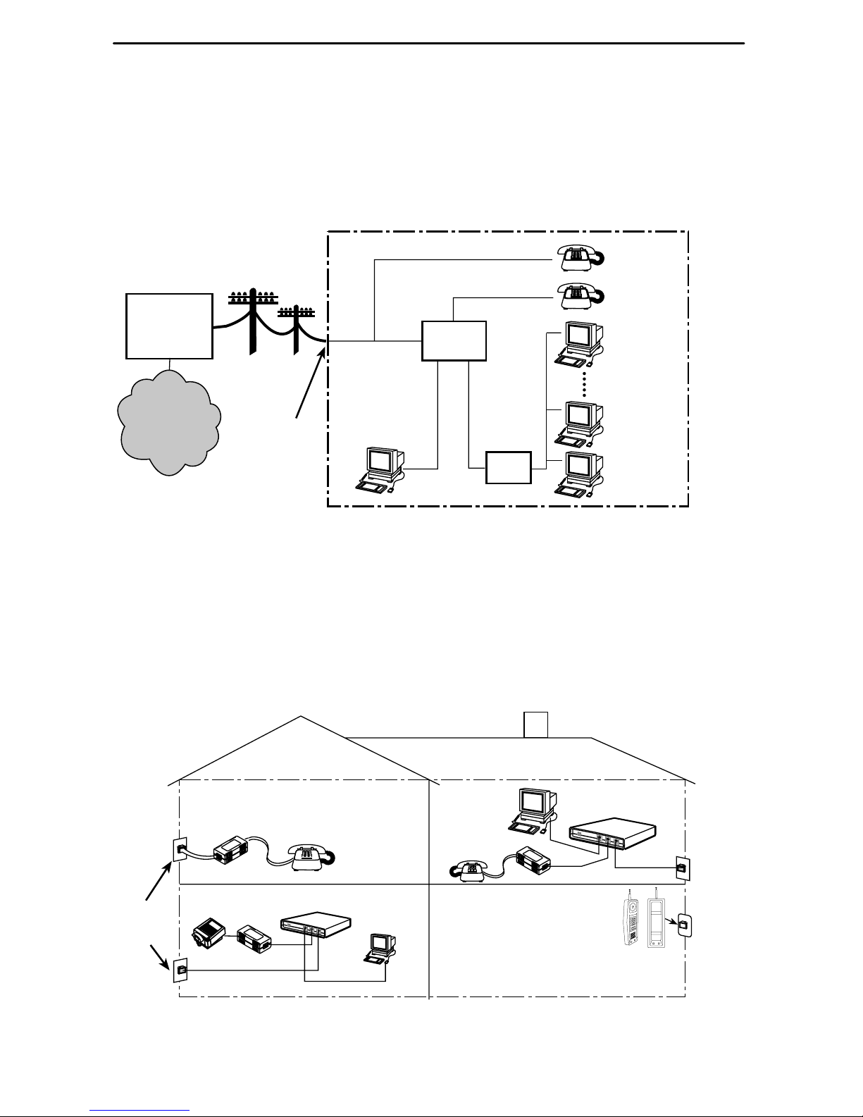
Hotwire MVL System
Copper pairs run from the central office (CO) to the customer premises (CP) to create
the local loop. The local loop terminates on the customer premises at the demarcation
point.
98-15930a-02
MVL
Modem
Customer Premises (CP)
MVL/POTS
Ethernet
Crossover
Cable
Ethernet
Cable
or
Central
Office
(CO)
Local Loop
Hub
MVL – Multiple Virtual Lines
POTS – Plain Old Telephone Service
End-user
Systems
(up to 32)
Network
Service
Provider
(NSP)
Demarcation
Point
MVL Access with a Hotwire MVL POTS Filter
When a Hotwire 6035 or 6040 MVL POTS Filter is used, one filter is installed for each
telephone on the same phone line as MVL.
99-16580
RJ11
Wall Jack
RJ11
Wall
Jack
MVL Modem
Customer
Premises (CP)
P
H
O
N
E
P
O
W
E
R
E
T
H
E
R
N
E
T
L
I
N
E
P
H
O
N
E
P
O
W
E
R
E
T
H
E
R
N
E
T
L
IN
E
FAX
MVL Modem
6035
Phone Filter
POTS Filter
6040
Wall Jack
Phone
Filter

3
NOTES:
In this document:
— A telephone is used to represent any equipment that plugs into a phone jack
and uses the POTS line, such as a phone, modem, or fax machine.
— End-user system is used to represent any PC with an Ethernet connection and
MVL-based service.
— Service provider is used to represent any Internet Service Provider (ISP) or
remote LAN access provider.
Before You Begin
Verify that your package contains the following:
-
Hotwire 6310 MVL Modem
-
MVL interface cable with RJ11 connectors
-
Power cord with power transformer
-
One ferrite choke
Be sure to register your warranty at www.paradyne.com/warranty.
Wiring and Cables You Need
The following wiring and standard connectors are used with this product:
-
Standard RJ11 wall jack for the MVL cabling.
-
Standard Ethernet 8-pin, non-keyed modular plug for a PC or workstation.
An Ethernet straight-through or crossover cable is used. Refer to Installing the
Hotwire 6310 MVL Modem on page 4 for Ethernet cable details.
MVL Phone Filter
Depending on the type of telephone handset and the quality of the home or business
wiring, a phone filter is recommended to improve data transmission throughput and
minimize background noise during a telephone conversation.
There are two Hotwire MVL Phone Filters:
H Hotwire 6035 MVL Phone Filter designed for use with a tabletop phone.
H Hotwire 6040 MVL Wall Jack Phone Filter designed for use with a wall phone.
4
Product-Related Documents
To install a phone filter, refer to the appropriate document:
Document Number Document Title
6035-A2-GN11 Hotwire 6035 MVL Phone Filter Installation Instructions
6040-A2-GN11 Hotwire 6040 MVL Wall Jack Phone Filter Installation
Instructions
Contact your sales or service representative to order additional product documentation.
Paradyne documents are available on the World Wide Web at www.paradyne.com.
Select Library → Technical Manual → Hotwire DSL & MVL Systems.
Installing the Hotwire 6310 MVL Modem
Place the Hotwire 6310 MVL Modem on a flat surface with clearance for the rear
connectors.
" Procedure
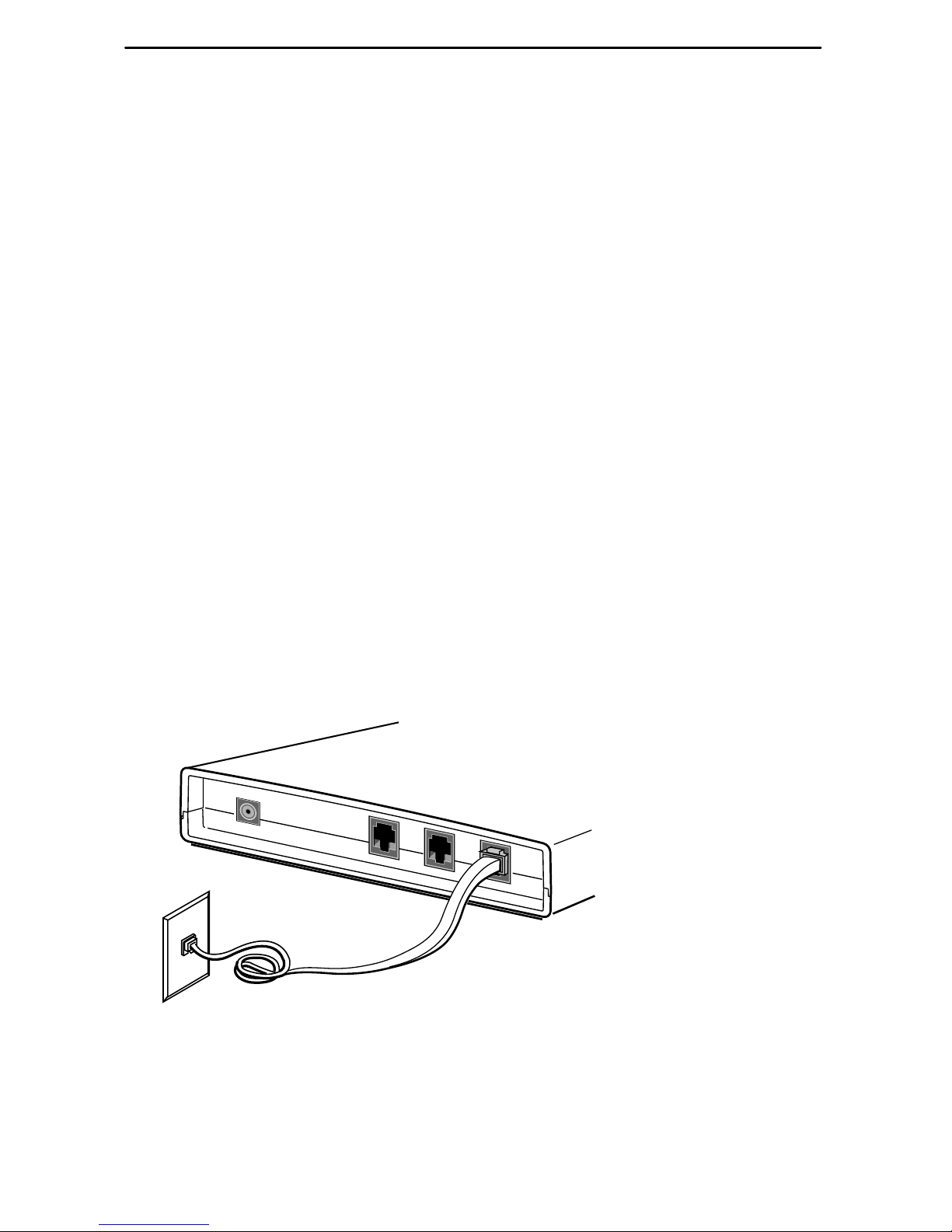
1. If a telephone is installed, unplug the telephone line from the RJ11 wall jack.
2. Use the supplied RJ11 6-pin interface cable for the MVL LINE connection. Insert
one end of the cable into the jack labeled LINE. Insert the other end of the cable
into the RJ11 wall jack.
PHONE
98-15895
RJ11
Wall Jack
POWER
ETHERNET
LINE
MVL Modem
5
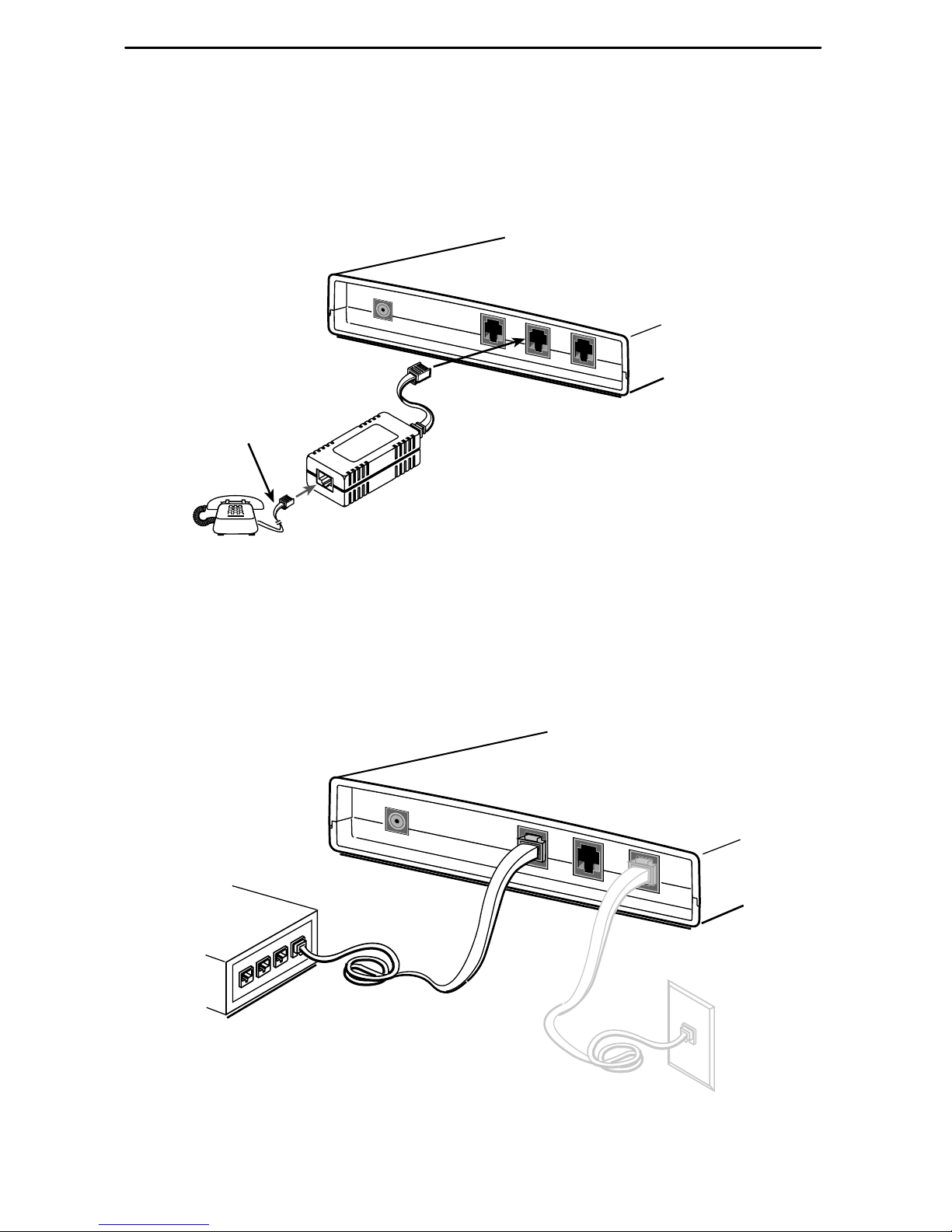
3. Connect a telephone (optional); go to Step 4 if you are not connecting a telephone
to the MVL modem.
The 6035 phone filter has a cable attached. Plug the other end of this cable into
the MVL modem jack labeled PHONE. Using the existing telephone interface cable
that was unplugged in Step 1, plug into the POTS filter jack labeled PHONE.
99-16239-01
MVL Modem
PHONE
POWER
ETHERNET
LINE
Supplied
Cable
Existing Cable
LINE
PHONE
4. Use an 8-pin Ethernet cable for the Ethernet connection. Insert one end of the
cable into the jack labeled ETHERNET.
H Use a straight-through cable and connect the other end to an Ethernet hub.
Do not connect a straight-through cable to the external hub’s UPLINK
connection (this connection requires a crossover cable),
PHONE
POWER
ETHERNET
LINE
MVL Modem
98-15906
Ethernet
Line
Ethernet
Hub
Ethernet
Cable
– or –
6
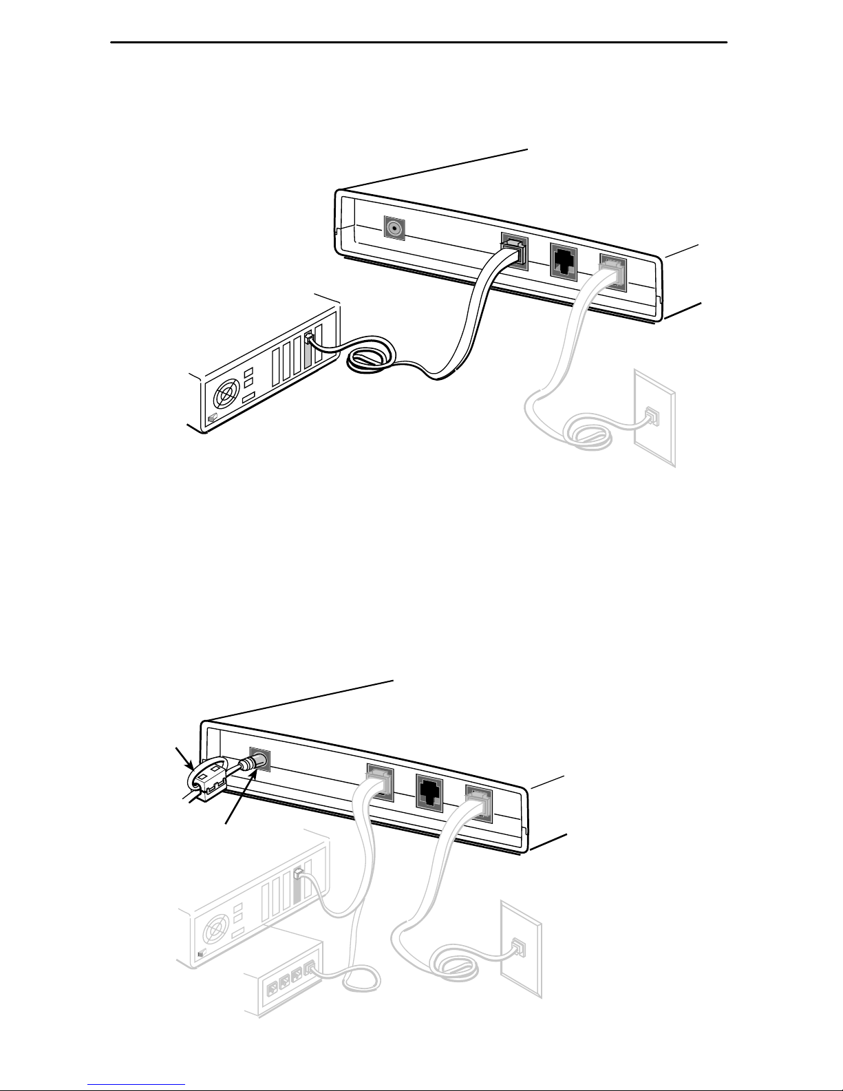
H Use an Ethernet crossover cable and connect the other end to a PC with an
Ethernet Network Interface Card (NIC) installed.
PHONE
POWER
ETHERNET
LINE
MVL Modem
98-15907
Ethernet
Line
PC with Ethernet
Network Interface
Card
Ethernet
Cable
For MVL modem cable pin assignments, refer to Cables & Connectors on page 10.
5. Insert the supplied power cord’s round end into the jack labeled POWER. Attach
the supplied ferrite choke as closely as possible to the MVL modem. Pass the
cable through the ferrite choke twice, creating a loop as shown. Close the two
halves around the ferrite choke and snap the ferrite choke shut. Plug the
transformer into an ac outlet.
PHONE
POWER
ETHERNET
LINE
MVL Modem
00-16352-01
Power
Jack
or
Ferrite
Choke
 Loading...