

Paradyne 5930 Installation Instructions Manual
5930-A2-GZ40-00 May 2005 1
5930 Lifeline POTS/ISDN Splitter
Installation Instructions
Document Number 5930-A2-GZ40-00
May 2005
About the 5930 POTS/ISDN Splitters
The 5930 POTS/ISDN splitters separate the DSL (Digital Subscriber Line) and
POTS (plain old telephone service) or ISDN (Integrated Services Digital Network)
frequencies. The 5930 POTS/ISDN Splitter chassis holds from two to eight
POTS/IDSN splitter cards, each of which supports 24 DSL subscriber lines:
The 1U Model 5930-B1-048 supports 2 cards and 48 DSL subscriber lines
The 3U Model 5930-B1-144 supports 6 cards and 144 DSL subscriber lines
The 4U Model 5930-B1-192 supports 8 cards and 192 DSL subscriber lines
The 5930 series shelves provide lifeline POTS: whenever a card is removed from
the shelf, POTS service is uninterrupted, ensuring that critical services like 911
remain available to the end user.
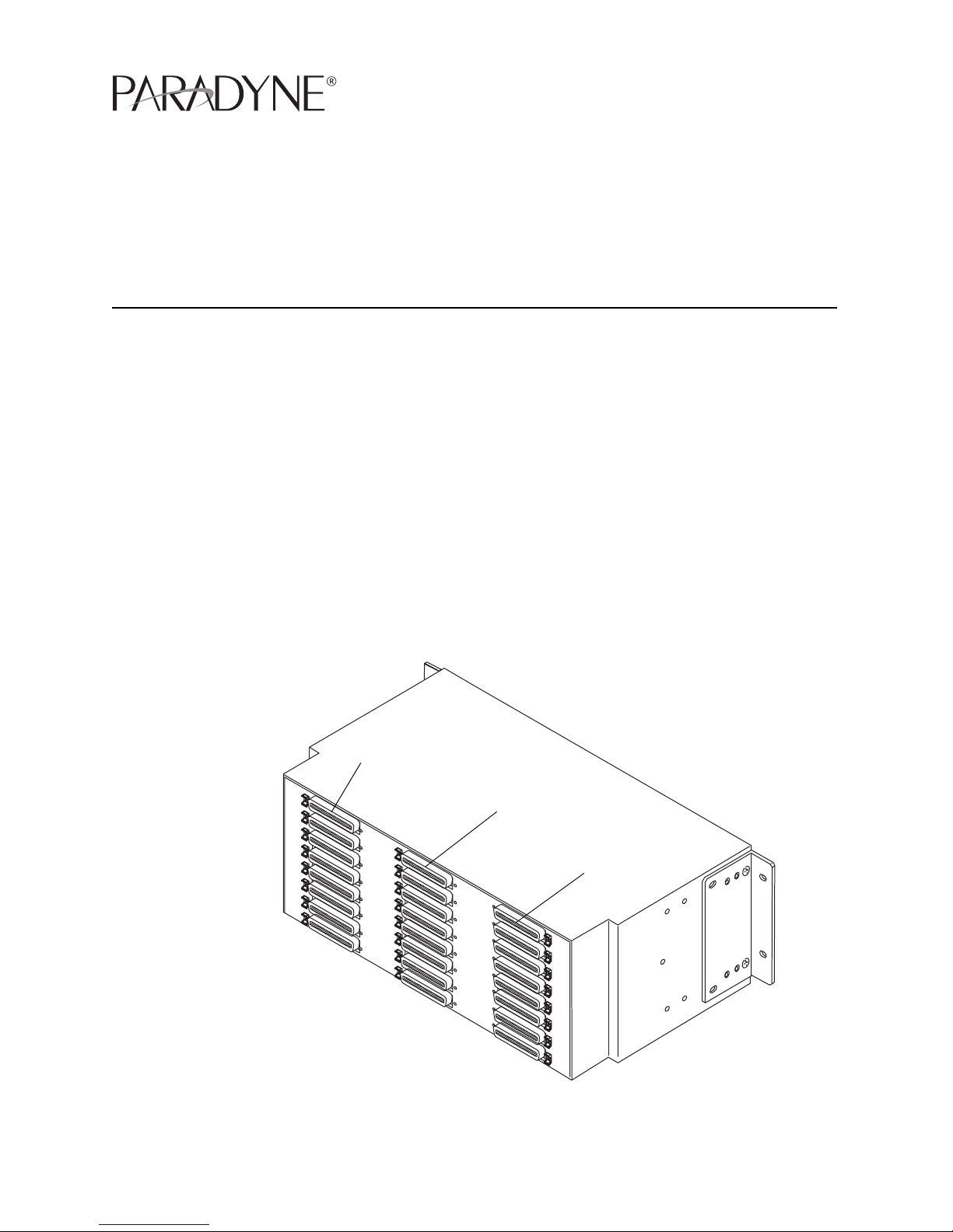
Figure 1. 5930-B1-192 Rear Connectors
05-17657
DSL Interface
Line Interface
PSTN Interface

2 May 2005 5930-A2-GZ40-00
With the emergence of ADSL2+ enhanced services like video, the POTS Splitter is
a vital part of the network. The innovative design of the 5900 series addresses
specific issues that affect video flow such as crosstalk and ring-trip problems. The
5900 Series is environmentally hardened to handle such locations as remote
cabinets as well as Central Offices.
Product-Related Documents
Paradyne documents are available on the World Wide Web at
www.paradyne.com. Select Library → Technical Manuals.
To order a paper copy of a Paradyne document, or to speak with a sales
representative, please call 1-727-530-2000.
Installation Overview
Installation of the POTS splitter card requires the following steps:
❑ Determining the cables you need
❑ Preparing the installation location and checking the package contents
❑ Installing the POTS splitter chassis
❑ Installing splitter cards in the chassis
❑ Connecting the cabling from the POTS splitter card connectors to the BLC
(Broadband Loop Carrier), local loop, and in-building wiring
❑ Securing the cables
Be sure to register your warranty at www.paradyne.com/warranty.
Cables You Need
Each of the POTS/ISDN splitter card interfaces in the 5930 chassis requires three
50-conductor cables with 50-pin Telco connectors. If every slot is populated and
used, you require:
6 cables for the Model 5930-B1-048
18 cables for the Model 5930-B1-144
24 cables for the Model 5930-B1-192
Use a minimum of 24 AWG (0.205 mm
2
).
5930-A2-GZ40-00 May 2005 3
Preparation
HANDLING PRECAUTIONS FOR
STATIC-SENSITIVE DEVICES
This product is designed to protect sensitive components from damage
due to electrostatic discharge (ESD) during normal operation. When
performing installation procedures, however, take proper static control
precautions to prevent damage to equipment. If you are not sure of the
proper static control precautions, contact your nearest sales or service
representative.
The installation location should be well ventilated, clean, and free of environmental
extremes. Allow clearance at the rear of the POTS splitter chassis to provide
access to the cables.
Read the Important Safety Instructions on page 11.
Tools Required
A large #3 or #4 Phillips screwdriver to install the chassis into a rack.
A flat-blade screwdriver to fasten the front panel and the cable heads.
5930 POTS/ISDN Splitter Chassis Installation
The POTS/ISDN splitter chassis is shipped with mounting brackets that allows it to
be mounted in a 19″ (483 mm) or 23″ (584 mm) cabinet or rack.
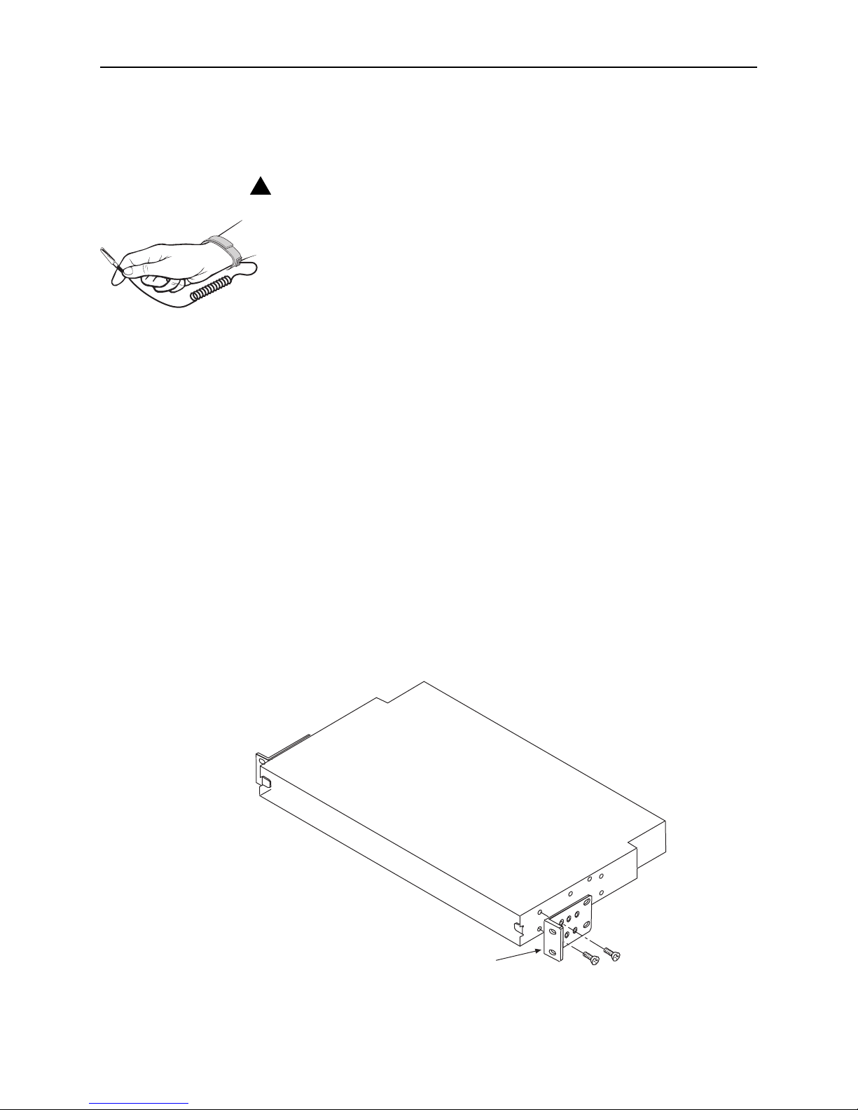
Figure 2. 5930-B1-048 Set Up for a 19-Inch Rack
!
05-17644
Mounting Brackets
4 May 2005 5930-A2-GZ40-00
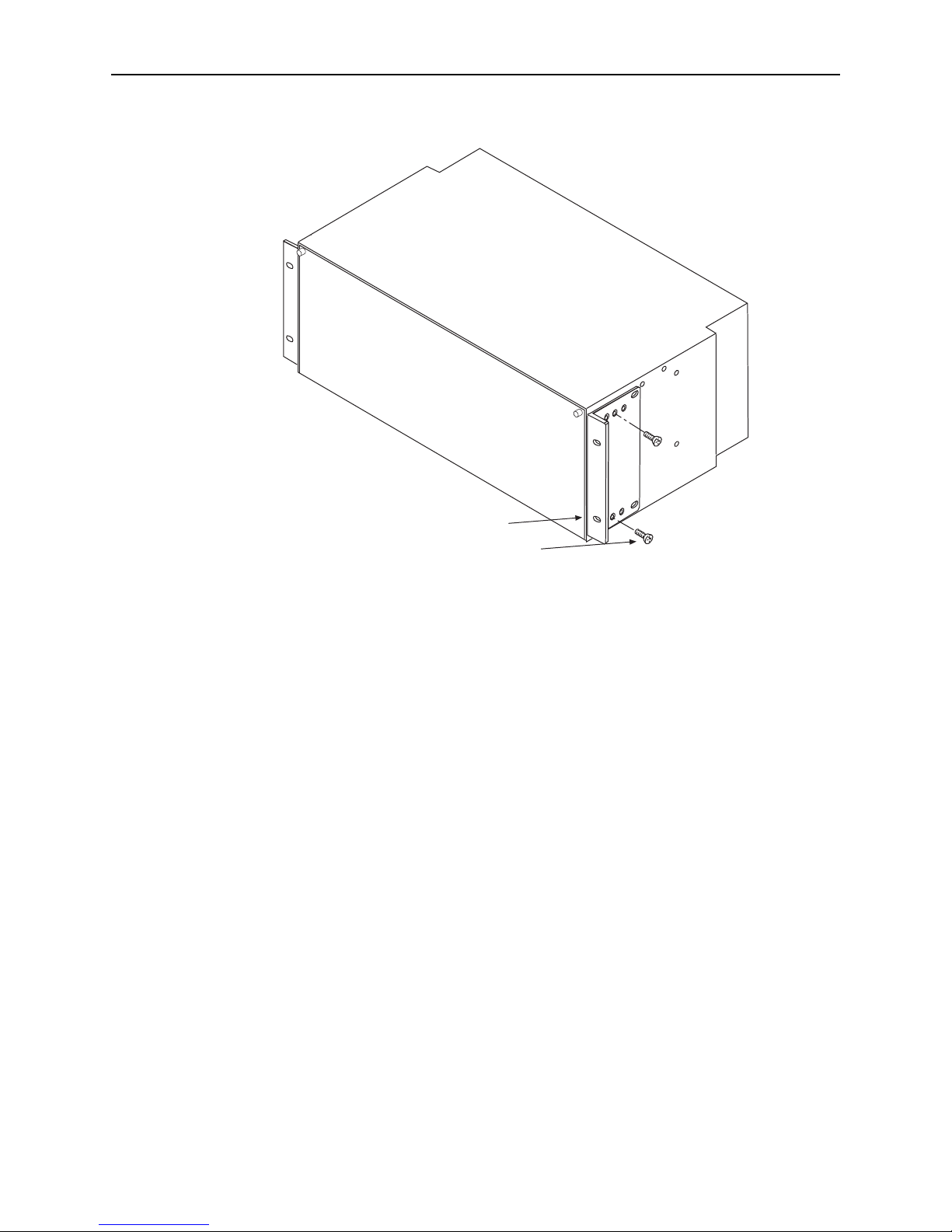
Figure 3. 5930-B1-192 Set Up for a 19-Inch Rack
In preparation for bracket and chassis installation, determine:
Whether the equipment will be rack-mounted.
Width of the rack: 19″ (483 mm) or 23″ (584 mm).
Whether the rack has mounting rails with threaded or non-threaded screw
holes.
The number of POTS/ISDN splitter chassis required.
NOTES:
Install chassis in the rack from the bottom up to maintain stability.
If access to the back of the unit will be inconvenient when the chassis is
mounted, connect the grounding wire before installing the chassis in the rack.
05-17648
Mounting Hardware
Mounting Brackets
 Loading...