

Paradyne 5920 Installation Instructions Manual

5920-A2-GZ40-00 May 2005 1
5920 POTS/ISDN Splitter
Installation Instructions
Document Number 5920-A2-GZ40-00
May 2005
About the 5920 POTS/ISDN Splitters
The 5920 POTS/ISDN splitters separate the DSL (Digital Subscriber Line) and
POTS (plain old telephone service) or ISDN (Integrated Services Digital Network)
frequencies. The 5920 POTS/ISDN Splitter chassis holds from two to 18
POTS/IDSN splitter cards, each of which supports 24 DSL subscriber lines:
The 1U Model 5920-B1-048 supports 2 cards and 48 DSL subscriber lines
The 3U Model 5920-B1-144 supports 6 cards and 144 DSL subscriber lines
The 4U Model 5920-B1-192 supports 8 cards and 192 DSL subscriber lines
The 9U Model 5920-B1-432 supports 18 cards and 432 DSL subscriber lines
The 5920 POTS/ISDN splitter shelf was specifically designed to fit the dimensions
of an ETSI rack and meets the standards for EMEA markets. With front mount
connectors, 5920s can be mounted back to back or against a wall, eliminating the
need for swing shelves.
With the emergence of ADSL2+ enhanced services like video, the POTS Splitter is
a vital part of the network. The innovative design of the 5900 series addresses
specific issues that affect video flow such as crosstalk and ring-trip problems. The
5900 Series is environmentally hardened to handle such locations as remote
cabinets as well as Central Offices.
Product-Related Documents
Paradyne documents are available on the World Wide Web at
www.paradyne.com. Select Library → Technical Manuals.
To order a paper copy of a Paradyne document, or to speak with a sales
representative, please call 1-727-530-2000.
Installation Overview
Installation of the POTS splitter card requires the following steps:
❑ Determining the cables you need
❑ Preparing the installation location and checking the package contents
2 May 2005 5920-A2-GZ40-00
❑ Installing the POTS splitter chassis
❑ Installing splitter cards in the chassis
❑ Connecting the cabling from the POTS splitter card connectors to the BLC
(Broadband Loop Carrier), local loop, and in-building wiring
❑ Securing the cables
Be sure to register your warranty at www.paradyne.com/warranty.
Cables You Need
Each of the POTS/ISDN splitter card interfaces in the 5920 chassis requires three
50-conductor cables with 50-pin Telco connectors. If every slot is populated and
used, you require:
6 cables for the Model 5920-B1-048
18 cables for the Model 5920-B1-144
24 cables for the Model 5920-B1-192
54 cables for the Model 5920-B1-432
Use a minimum of 24 AWG (0.205 mm
2
).
Preparation
HANDLING PRECAUTIONS FOR
STATIC-SENSITIVE DEVICES
This product is designed to protect sensitive components from damage
due to electrostatic discharge (ESD) during normal operation. When
performing installation procedures, however, take proper static control
precautions to prevent damage to equipment. If you are not sure of the
proper static control precautions, contact your nearest sales or service
representative.
The installation location should be well ventilated, clean, and free of environmental
extremes. Allow clearance at the front of the POTS splitter chassis to provide
access to the cables.
Read the Important Safety Instructions on page 9.
Tools Required
A medium #2 Phillips screwdriver to tighten the POTS/ISDN splitter card
fasteners.
A large #3 or #4 Phillips screwdriver to install the chassis into a rack.
A flat-blade screwdriver to fasten cable heads.
!
5920-A2-GZ40-00 May 2005 3
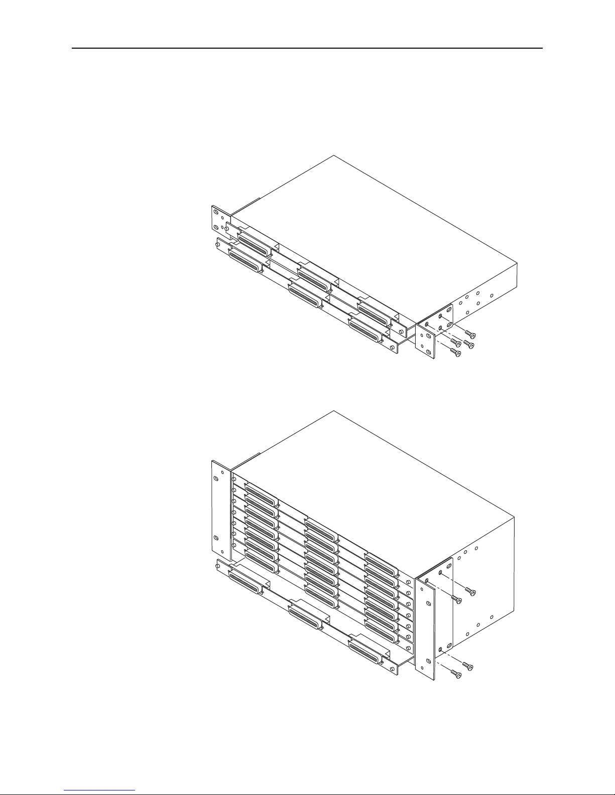
5920 POTS/ISDN Splitter Chassis Installation
The POTS/ISDN splitter chassis is shipped with mounting brackets that allows it to
be mounted in a 19″ (483 mm) or 23″ (584 mm) cabinet or rack.
Figure 1. 5920-B1-048 Set Up for a 19-Inch Rack
Figure 2. 5920-B1-192 Set Up for a 19-Inch Rack
05-17650
DSL Interface
Line Interface
PSTN Interface
05-17652
DSL Interface
Line Interface
PSTN Interface
 Loading...