

Paradyne 5910 Installation Instructions Manual

5910-A2-GZ40-00 May 2005 1
5910 High Density Lifeline POTS Splitter
Installation Instructions
Document Number 5910-A2-GZ40-00
May 2005
About the 5910 POTS Splitter
The 5910 is a double-density POTS splitter that separates the DSL (Digital
Subscriber Line) and POTS (plain old telephone service) frequencies. When
populated with 8 POTS splitter cards, it delivers 192 ports in 2U of a standard rack.
The 5910 provides make-before-break lifeline POTS. Whenever a card is removed
from the shelf, POTS service is uninterrupted, ensuring that critical services like
911 remain available to the end user.
With the emergence of ADSL2+ enhanced services like video, the POTS Splitter is
a vital part of the network. The innovative design of the 5900 series addresses
specific issues that affect video flow such as crosstalk and ring-trip problems. The
5900 Series is environmentally hardened to handle such locations as remote
cabinets as well as Central Offices.
Product-Related Documents
Paradyne documents are available on the World Wide Web at
www.paradyne.com. Select Library → Technical Manuals
To order a paper copy of a Paradyne document, or to speak with a sales
representative, please call 1-727-530-2000.
Installation Overview
Installation of the POTS splitter card requires the following steps:
❑ Determining the cables you need
❑ Preparing the installation location and checking the package contents
❑ Installing the POTS splitter chassis
❑ Installing splitter modules in the chassis
❑ Connecting the cabling from the POTS splitter card connectors to a BLC
(Broadband Loop Carrier), local loop, and in-building wiring
❑ Securing the cables
Be sure to register your warranty at www.paradyne.com/warranty.
2 May 2005 5910-A2-GZ40-00
Cables You Need
Each of the three POTS Splitter card interfaces in each of the eight modules in the
5910 POTS splitter requires a 50-conductor cable with a 50-pin Telco connector,
for a total of 24 cables for 192 ports:
The DSL interface connects to the DSL port connector of a DSLAM or BLC.
The Line interface connects to the in-building POTS and ADSL customer
premises equipment (CPE).
The PSTN interface connects to the PBX or PSTN.
See Connector Pin Numbers on page 6. Use a minimum of 24 AWG (0.205 mm
2
).
Preparation
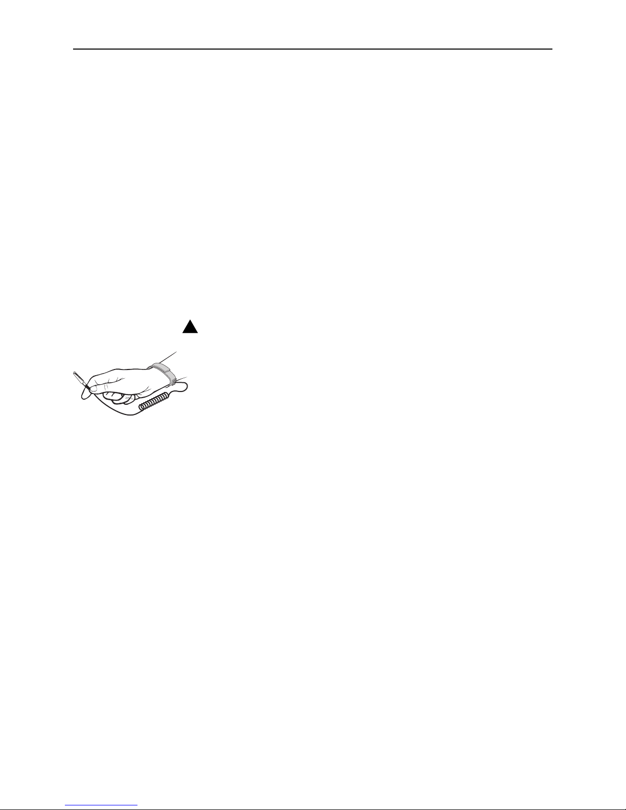
HANDLING PRECAUTIONS FOR
STATIC-SENSITIVE DEVICES
This product is designed to protect sensitive components from damage
due to electrostatic discharge (ESD) during normal operation. When
performing installation procedures, however, take proper static control
precautions to prevent damage to equipment. If you are not sure of the
proper static control precautions, contact your nearest sales or service
representative.
The installation location should be well ventilated, clean, and free of environmental
extremes. Allow clearance at the front and back of the POTS splitter chassis to
provide access to the cables.
Read the Important Safety Instructions on page 7.
Tools Required
A large #3 or #4 Phillips screwdriver to install the chassis into a rack.
A flat-blade screwdriver to fasten cable heads.
POTS Splitter Chassis Installation
The POTS splitter chassis is shipped with mounting brackets that allows it to be
center-mounted in a 19″ (483 mm) or 23″ (584 mm) cabinet or rack.
In preparation for bracket and chassis installation, determine:
Whether the equipment will be rack-mounted.
Width of the rack: 19″ (483 mm) or 23″ (584 mm).
Whether the rack has mounting rails with threaded or non-threaded screw
holes.
!

5910-A2-GZ40-00 May 2005 3
The number of POTS splitters required. The 5910 POTS splitter supports up to
192 DSL lines.
NOTE:
Install chassis in the rack from the bottom up to maintain stability.
Installation into a Rack without Threaded Screw Holes
Procedure
To install a chassis in a rack without threaded screw holes:
1. Install the mounting brackets appropriate for your rack.
2. Determine where the chassis will be placed in the rack. Mark the rail where the
four holes in the mounting brackets will be.
3. Slide a self-retaining nut onto each marked rail hole and align the hole of the
nut with the hole in the rail.
4. Line up the chassis mounting brackets with the self-retaining nuts.
5. Holding the chassis in place, loosely install the bottom screws first and then
the top screws.
6. Tighten all screws firmly using a Phillips screwdriver.
Repeat the process for each POTS splitter chassis. POTS splitter chassis can be
mounted directly on top of each other.
Installation into a Rack with Threaded Screw Holes
Procedure
To install a chassis in a rack with threaded screw holes:
1. Install the mounting brackets appropriate for your rack.
2. Determine where the chassis will be placed in the rack.
3. Line up the chassis mounting brackets with the rail holes.
4. Holding the chassis in place, loosely install the bottom screws first and then
the top screws.
5. Tighten all screws firmly with a Phillips screwdriver.
Repeat the process for each POTS splitter chassis. POTS splitter chassis can be
mounted directly on top of each other.
 Loading...