

Paradyne 5030 Installation Instructions Manual
1
SuperLine 5030 POTS Splitter
Installation Instructions
Document Number 5030-A2-GN11-00
September 1999
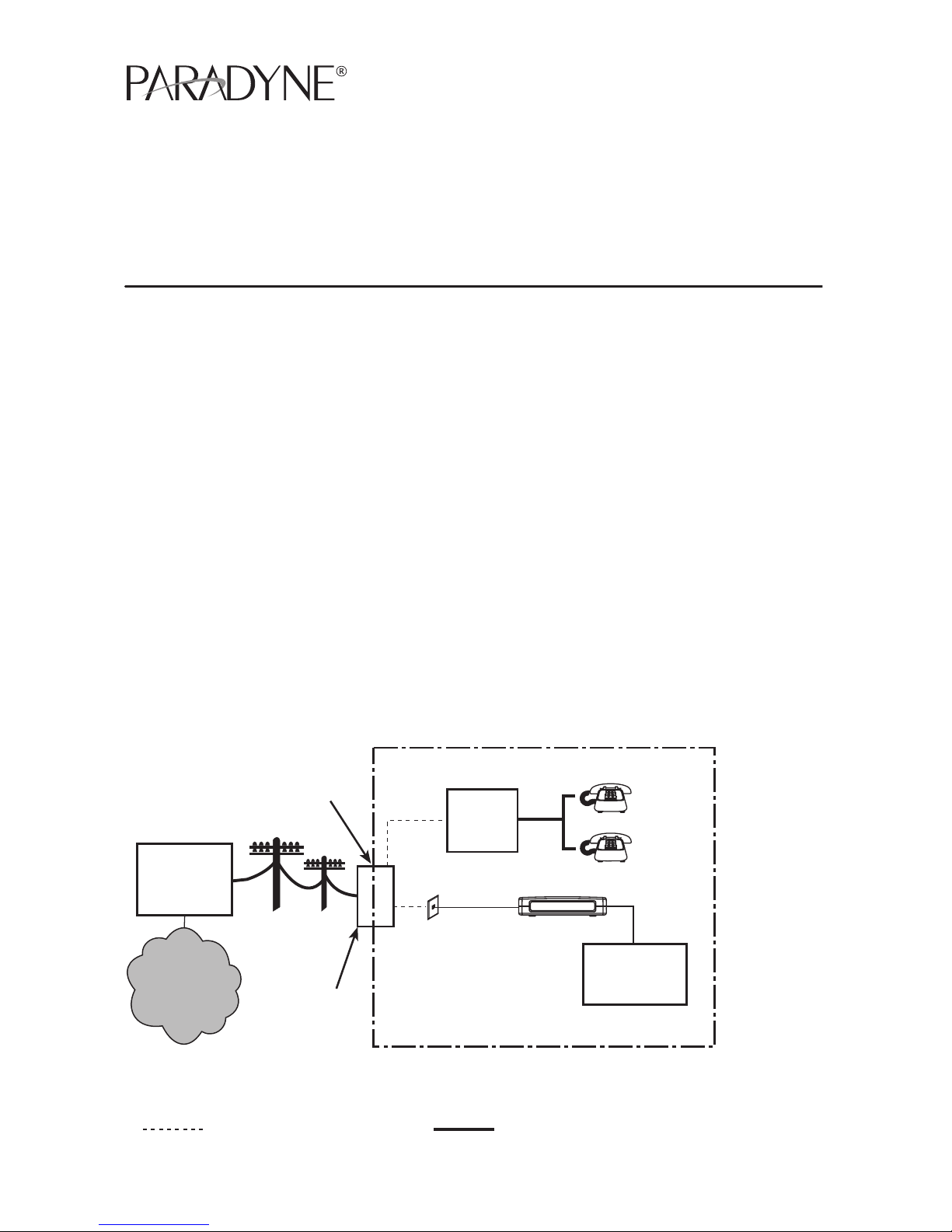
What Does the POTS Splitter Do?
The POTS (Plain Old Telephone Service) splitter and SuperLine IAD are components
in the SuperLine system. This system provides multiple phone lines and optional
Ethernet service over traditional twisted-pair copper telephone wiring.
The POTS splitter filters out the SuperLine signal and allows the POTS frequencies to
pass through. The SuperLine IAD and separate telephones can function simultaneously
over the same pair of copper wires at the customer premises when a POTS splitter is
used at both ends of the local loop. The POTS splitter eliminates the need for individual
phone filters.
Copper pairs run from the central office to the customer premises to create the local
loop. The local loop terminates on the customer premises at the demarcation point in a
punchdown block or network interface device (NID).
Wiring is connected from the demarcation point to the POTS splitter and to the
SuperLine jack.
99-16513
Punchdown
Block or NID
New Wiring Connections Existing Wiring (POTS)
Customer Premises (CP)
Central
Office
(CO)
Demarcation
Point
Local Loop
CP
POTS
Splitter
POTS – Plain Old Telephone Service
NID – Network Interface Device
POTS
Network
Service
Provider
(NSP)
Telephones
and Other
Devices
SuperLine IAD
SuperLine
Jack

2
Preparation
Verify that the local loop POTS service is connected to the POTS/SuperLine network at
the punchdown block or NID.
For information about the SuperLine Integrated Access Device (IAD), which is the
customer premises equipment that will be connected to the SuperLine jack, refer to:
Document Number Document Title
6500-A2-GN10
SuperLine IAD, Models 6501, 6502, 6510, 6511, and
6512, Installation Instructions
Package Checklist
Verify that your package contains the following:
-
POTS splitter and housing with closure screw
-
Small plastic bag with two 8-15 x 1″ Type A combination Phillips/slotted-head
screws and two 1″ plastic anchors
Tools Required
-
Flat-blade screwdriver to tighten terminal screws
-
3/8″ nut driver to close housing securely
-
Phillips-head or combination Phillips/slotted-head screwdriver to mount the housing
-
Drill and 3/16″ drill bit to mount the housing in cement or cinder block
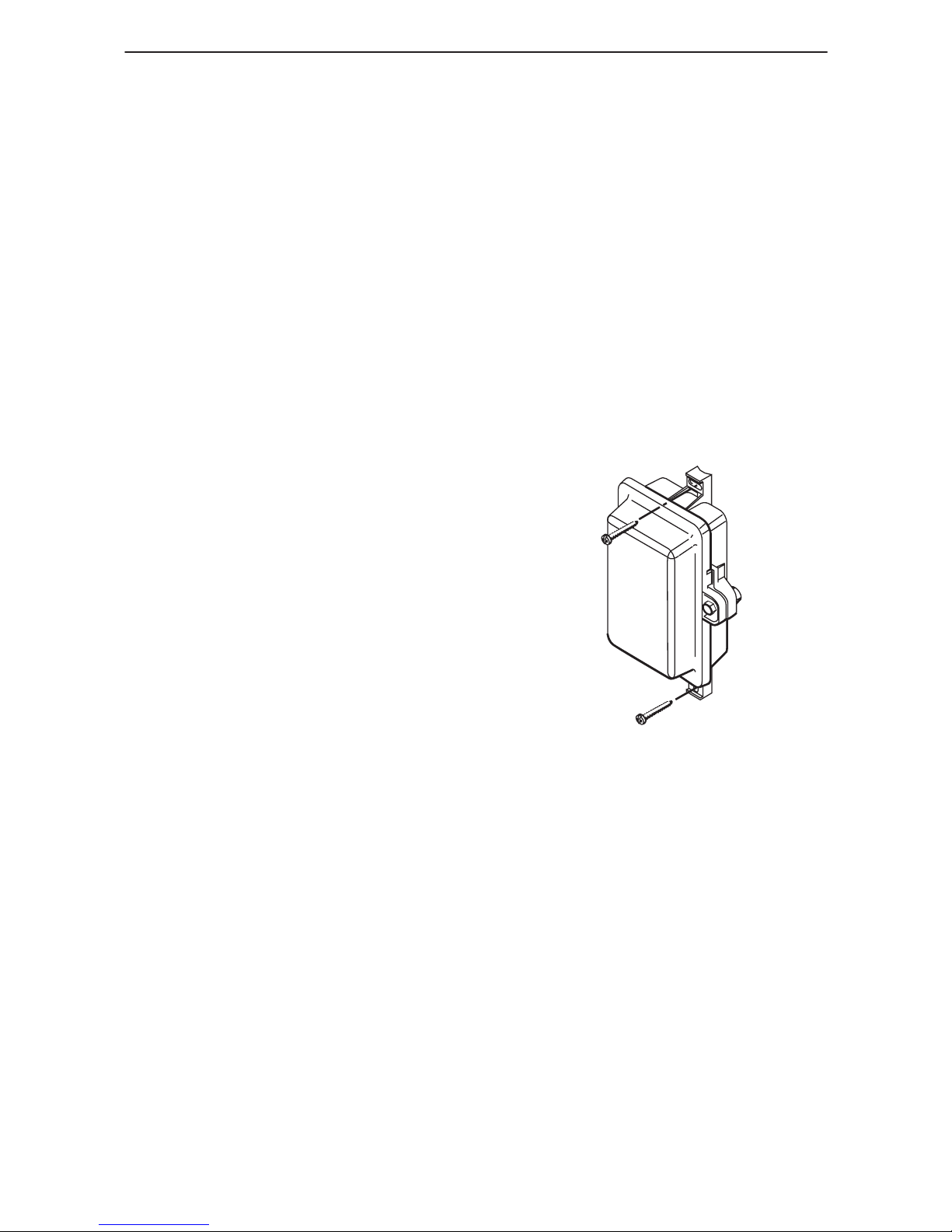
97-15247
POTS Splitter Housing
3
Mounting the POTS Splitter Housing
The POTS splitter can be placed:
H On the outside of the building near the NID or punchdown block, or
H Inside the building.
When mounted outside, the POTS splitter must be installed at or above the height of
the NID, and should be a minimum of three feet above ground.
At the front of the housing, align the housing to open from the right with the rubber
grommet for cable access facing downward. Place the housing upright as shown. Use a
Phillips-head or combination Phillips/slotted-head screwdriver and the screws included
in the package.
If mounting to:
H Cement or cinder block: use a drill and
and 3/16″ masonry drill bit to install the
two plastic anchors first. Then, install the
two 8-15 x 1″ Type A screws.
H Wood: install only the two 8-15 x 1″
Type A screws and discard the
plastic anchors.
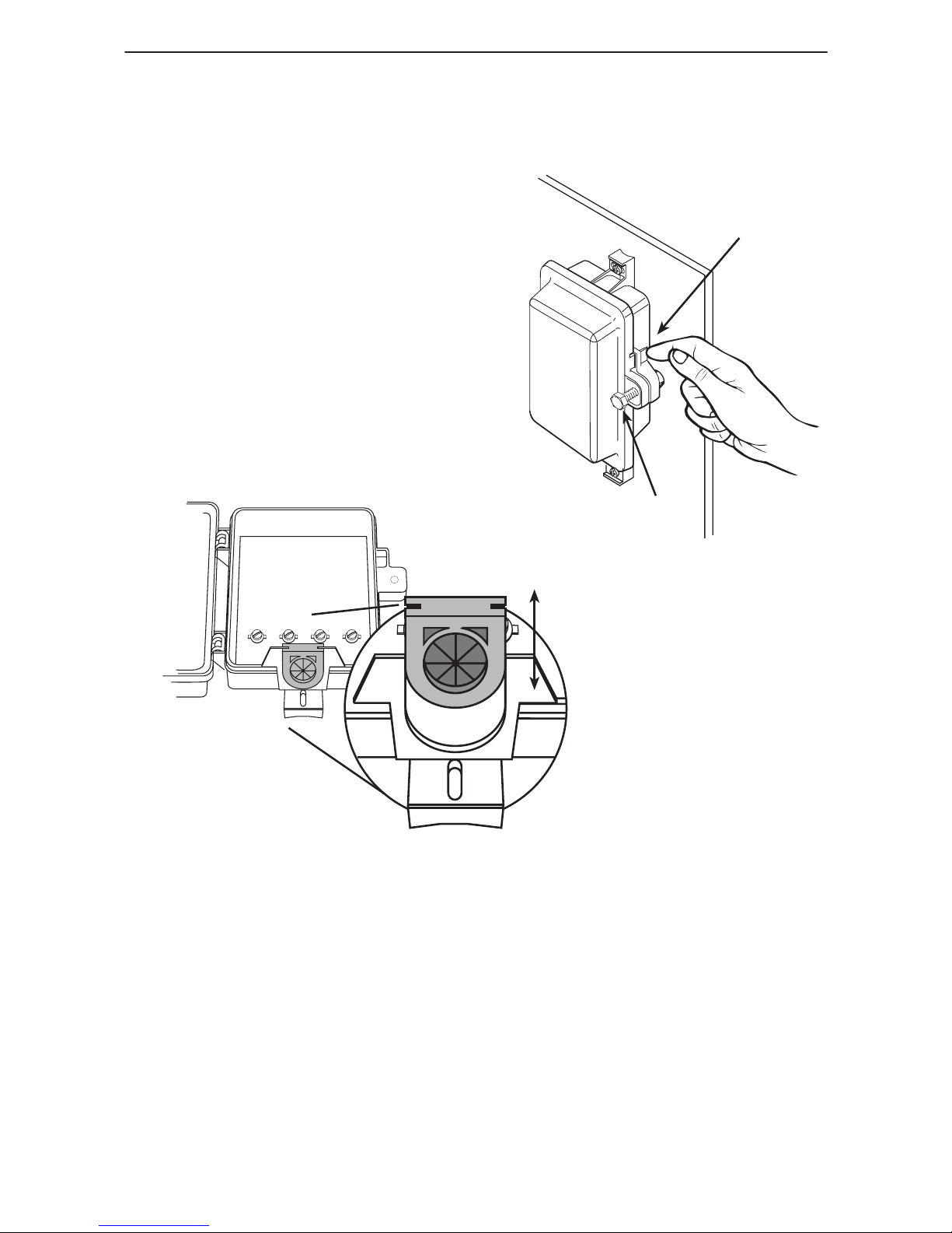
97-15437-01
Lever
Closure
Screw
4
Preparing the POTS Splitter
" Procedure
1. Unscrew the closure screw and open
the housing by pressing on the lever
on the right above the closure screw.
2. Remove the rubber grommet at the base
of the POTS splitter.
3. Make a small diagonal cut in the rubber
grommet to feed the wiring through.
4. Replace the rubber
grommet at the
base of the POTS splitter.
P1 P2 P3 P4
97-15256
Rubber
Grommet
Base of
POTS Splitter
 Loading...