

Page 1
TM
2-Slot Power Supply
Installation Instructions
Document Number 9000-A2-GN1A-10
April 1998
Before You Begin
The 2-slot housing can hold one power supply , which is already installed in the housing.
Should you need to replace this power supply , be sure to review the following
information.
CAUTION:
Refer installation of power supplies to qualified service personnel.
!
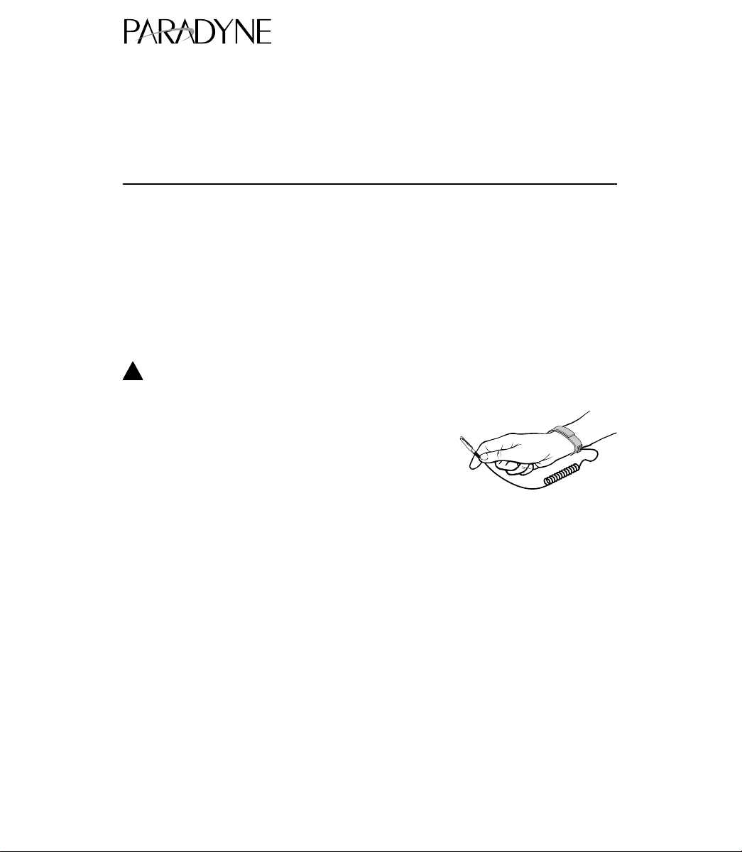
HANDLING PRECAUTIONS FOR ST ATIC-SENSITIVE DEVICES
This product is designed to protect sensitive components from
damage due to electrostatic discharge (ESD) during normal
operation. When performing installation procedures,
however, take proper static control precautions to
prevent damage to equipment. If you are not sure
of the proper static control precautions, contact
your nearest sales or service representative.
496-15149
Package Checklist
Verify that your package contains the following:
An ac power supply (See following specifications.)
An ac power cord
1
Page 2
Technical Specifications
Specification Criteria
Rated Voltage (nominal) 100–250 Vac, 50/60 Hz
Rated Current 1.0 Amps
Operating V oltage Range (limits) 90–265 Vac 47–63 Hz
Power Consumption (typical) 120 Vac 29.7 watts 452 mA
230 Vac 29.9 watts 270 mA
Result: 102 Btu per hour
Installing a Replacement Power Supply
Install a replacement power supply using the following instructions.
!
WARNING:
Before you remove the power supply module, you
cord from the power receptacle and from the rear of the housing before
attempting to remove the module.
must
unplug the power
1. Unplug the power cord from the power receptacle and from the rear of the housing.
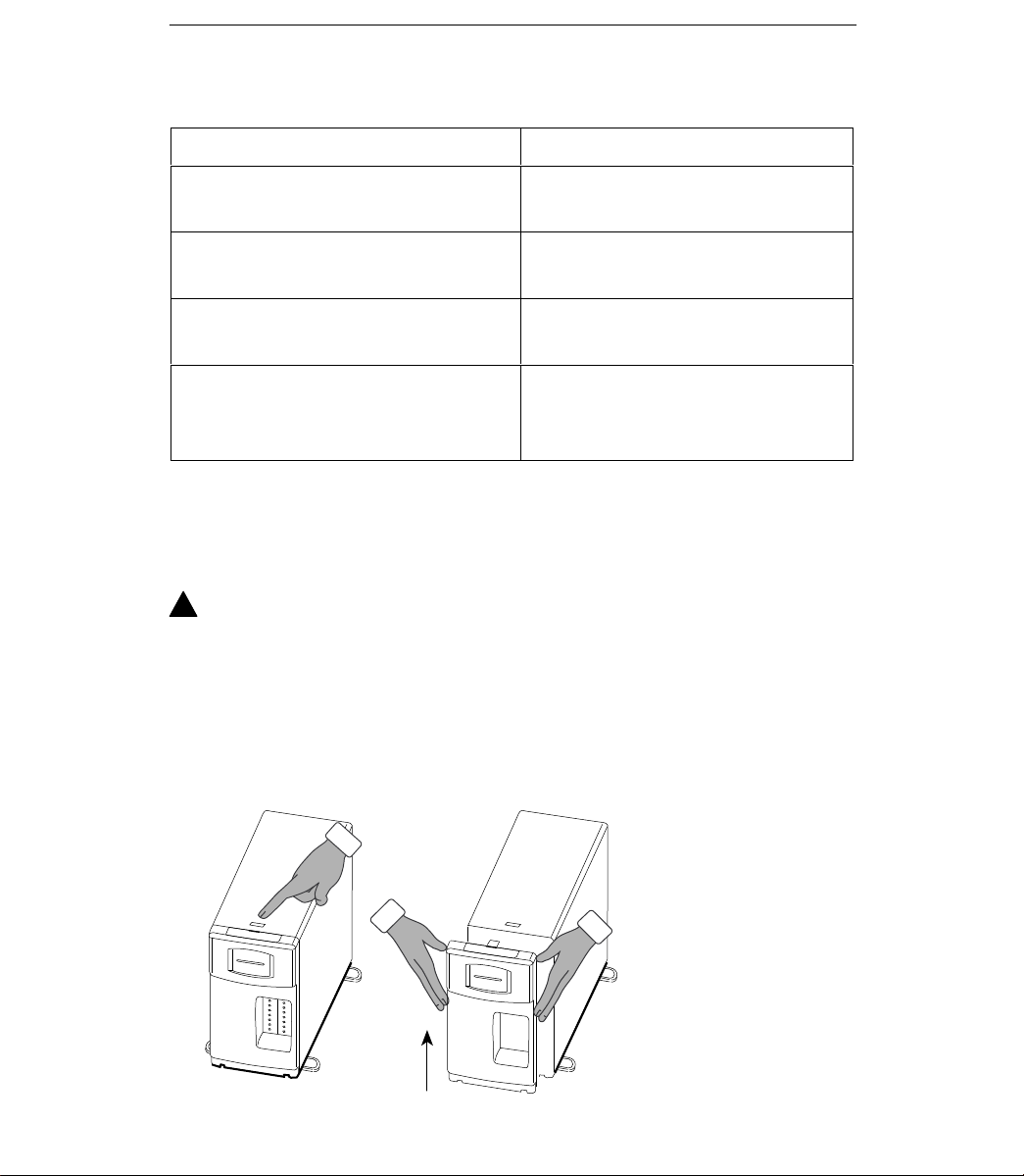
2. Remove the front bezel by depressing the latch at the top of the housing and lifting
the bezel out of the two slots in the bottom of the housing.
496-15123
2
Page 3

3. Unscrew the two screws on the current power supply using a flatblade screwdriver.
4. Remove the current power supply by pulling on the handle.
496-15126
5. Remove the new power supply from its shipping box. Handle only by the top and
bottom edges of the sheet metal bracket to avoid damaging it.
6. At the front of the housing, use the attached handle on the power supply to
carefully slide the housing into the slot towards the midplane until you feel it
connect. Be sure that you slide the power supply in using the guides provided on
the housing.
7. Tighten the two screws on the power supply using the screwdriver.
8. Reattach the front bezel to the housing.
9. Reattach the power cord.
Power-Up Verification
!
WARNING:
The power cord contains a 3-wire grounding-type plug which has a
grounding pin. This is a safety feature. Grounding of the carrier is vital to
ensure safe operation. Do not defeat the purpose of the grounding plug by
modifying it or by using an adapter.
Prior to installation, use an outlet tester or voltmeter to check the AC
receptacle for earth ground. If the power source does not provide a ground
connection, consult an electrician to determine another method of grounding
the carrier before proceeding with the installation.
3
Page 4

Verification Checklist
-
Did the NAM’s OK LED light? If not, see
Troubleshooting
.
Troubleshooting
Symptom Possible Cause Solutions
No power.
If you are still having problems with the power supply , contact your service
representative.
The power cord is not
securely plugged into the
wall receptacle, or is not
connected to the power
inlet at the rear of the
housing.
The wall receptacle has no
power.
Power supply is not fully
inserted into the housing.
Power supply is defective. Replace power supply .
Check that the power cord
is securely attached at both
ends.
Check the wall receptacle
power by plugging in some
equipment that is known to
be working.
Check the circuit breaker.
Reinstall the power supply ,
making sure that you gently
push it all the way into the
housing.
Power Failure Recovery
In cases of loss and restoration of nominal voltage conditions, this product
automatically restores to service without manual intervention.
*9000–A2–GN1A–10*
Copyright E 1998 Paradyne Corporation
4
 Loading...