

Page 1

GranDSLAM™ 4200
ATM Stackable DSLAM
Installation Guide
Document No. 4200-A2-GN20-10
October 2002
Page 2

Copyright © 2002 Paradyne Corporation.
Al l rig h t s res erve d.
Printed in U.S.A.
Notice
This publi cation is protected by federal copyright la w. No part of this publication ma y be copied or distributed,
transmitt ed, tr anscri bed, stor ed in a retrie v al syst em, or tr anslat ed into an y human or comput er langu age in any form or
by any mea ns, electronic, mechan ical, magnetic, manual or otherwise, or disclosed to third parties without the express
written permission of Paradyne Corporation, 8545 126th Ave. N., Largo , FL 33773.
Par adyne Corporation makes no representation or warranties with respect to the contents hereof and specifically
disclaims any implied warranties of merchantability or fitness for a particular purpose. Further, Paradyne Corporation
reserves the right to revise this publication and to make changes from time to time in the contents hereof without
obligation of Paradyne Corporation to notify any person of such revision or changes.
Changes and enhancements to the product and to the information herein will be documented and issued as a new
release to this manual.
W arranty, Sales, Service, and Tra ining Informatio n
Contact your local sales representative, service representative, or distributor directly for any help needed. For
additional information concerning warranty, sal es, service, repair , installation, documentation, training, distri butor
locations , or Paradyne worldwide off ice locations, use one of the following methods:
Internet: Visit the Paradyne World Wide Web site at www.paradyne.com. (Be sure to register your warranty at
www.paradyne.com/warranty.)
Telephone: Call our automated system to receive current information by fax or to speak with a company
representative.
— Within the U.S.A., call 1-800-870- 2221
— Outside the U.S.A., call 1-727-530- 2340
Document Feedback
We welcome your comments and suggestions about this document. Please mail them to Technical Publications,
Par adyne Corporation, 8545 126th Av e. N., Largo, FL 33773, or sen d e-mail to userdoc@paradyne.com. Include the
number and title of this document in your corresp ondence. Please include your name and phone number if you are
willing to pro vide additional clarificati on.
Trademarks
ACCULINK, COMSPHERE, F rameSaver, Hotwire, MVL, NextEDGE, OpenLane, Performance Wizard are register ed
trademarks of Paradyne Corporation. BitStorm, EtherLoop, GranDSLAM, GrandVIEW, ReachDSL, StormTracker, and
TruePut are trademarks of Paradyne Corporation. All othe r products and services mentioned herein are the
trademarks, service marks, registered trademarks, or registered service marks of their respective owners.
A
October 2002 4200-A2-GN20-10
Page 3

!
Importa nt Safety Instructi ons
1. Read and follow all warning notices and instructions marked on the product or included in the manual.
2. Do not attempt to service this product yourself, as openi ng or removing covers may expose you to dangerous high
voltage poi nts or other risks. Refer all servi cing to qualified service personnel.
3. FUSE WARNING: If DC input power is connected to the unit, an energy hazard (a potential equal to or greater
than 240VA) may exist at the fuse holder. When in stalling or replacing either of the alarm-indicating fuses, do not
contact metal parts of the fuse spring arm, which may be energi z ed, e v en after the fuse has trippe d. Nev e r remov e
the plastic fuse cap from the fuse; it is there to protect against inadvertent contact with the spring arm. Refer all
fuse installation/replacement to qualified service personnel who have been trained on this equipment.
CAUTION: FOR CONTINUED PROTECTION AGAINST RISK OF FIRE, REPLACE ONLY WITH THE SAME
TYPE AND RATING OF FUSE. Use a fuse that is rated for a maximum 60 VDC, 3.5A (Model 4210) or 4A
(Models 4220/4230).
ATTENTION: Pour ne pas comprom e ttre la protection contre le s risques d’incendie, remplacer par un fusi ble de
même type et de mêmes caractéristiques nominales.
4. This product is to be ins talled only in a Restricted Access Locat ion (dedicated equipment rooms, equipment
closets or the like) in accordance with articles 110-16, 110-17 and 110-18 of the National Electrical Code,
ANSI/NFPA 70.
5. This product is to be connected to a 48 VDC SELV sup ply source that is electrically isolated from the ac source.
The positiv e terminal of the 48 VDC source is to be reliably conne cted to earth. Connect a green/yellow earthing
(grounding) wire to the protective earthing (grounding) lug connector, identified by the prot ective earth symbol on
the chassis.
6. A readily access ible disconnect device as part of the building installation shall be incorporated in fixed wiring. The
disconnect device (a 48 VDC, 20A, single pole ci rcuit breaker or switch) must be included in the unground ed
supply conductor. Over current protection must be included with a 20A, 48 VDC fus e or ci rcuit breaker in the
ungrounded conductor. Use minimum 18 AWG fixed power source wires with strain retention.
7. Input power to the ALARM rela y int erf ac e (locat ed on the front pan el of the enc losure ) must not e xceed 30V rms or
60 VDC.
8. Do not allow anything to rest on the power cord and do not locate the product where persons will walk on the
power cord.
9. Slots and openings in th e cabinet are provided for ventilation. To ensure reliab le operation of the product and to
protect it from overheating, these sl ots and openings must not be blocked or covered.
10. General purpose cables are described for use with this product. Special cables, which may be required by the
regulatory inspection authority for the installation site, are the responsibility of the customer. To reduce the risk of
fire, use a UL Listed or CSA Certified, minimum No. 26 AWG (0.128 mm
comparable cables certified for use in the country of installation.
11. A rare phenomenon can create a voltage potential between the earth gr ounds of two or more buildings. If products
installed in se para te buildings ar e interconnected, the voltage potential may cause a hazardous condition.
Consult a qualifi ed electrical consultant to determine whether or not this phenomenon exists and, if necessary,
implement corrective action prior to interconnecting the products.
12. In addition, if the equipment is to be used with telecommunications circuits, tak e the following precau tions:
— Nev er i nstall telephone wiring during a lightning st orm.
— Nev er install telephone jacks in wet locations unless the jack is specifically designed for wet locations .
— Nev er touch uninsulated telephone wires or terminals unless the telephone line has been disconnected at the
network inter face.
— Use caution when installing or modifying telephone lines.
— Av oid using a telephone (other than a c ordless type) during an electrical storm. There m ay be a remote ri sk of
electric shock from lightning.
— Do not use the telephon e to rep ort a gas leak in the vi cinity of the leak.
2
) telecommunicat ion cable, or
4200-A2-GN20-10 October 2002
B
Page 4

13. The equipment is intended for installation in a max. 65° C ambient temperature, in an environment that is free of
dust and dirt.
14. When installed in the final configuration, the product must comply with the applicable Safety Standards and
regulatory requirements of the country in which it is installed. If necessary, consult with the appropriate regulatory
agencies and inspection authorities to ensure compl iance.
15. Do not phys ically stack more than five (5) 42xx units high. Physi cal stability has not been e valuated for stacking
higher than five units, and any configura ti on greater than five may result in an unstable ( ti p-over) condition. Ensure
that the f our (4) rubber feet supplied with the product have been instal led on the bottom of each unit prior to
stacking any 42xx units on top of one another.
16. If the equipment has an internal POTS splitter, then to be compliant with the Bellcore NEBS requirements
GR-1089-CORE, secti ons 4.2 .2 (Curr ent Li miting Protect ors) an d 4.5 .11 (Cur rent Lim iting Prot ector Tests ), current
limiting protectors shall be used on the DSL lines entering the facility.
EMI Notices
!
UNITED STATES – EMI NOTICE:
This equipment has been test ed and found to comply with the limits for a Class A digital device, pursuant
to Part 15 of the FCC rules. These lim its are designed to provide reasonable protection against harm ful
interference when the equipment is operated in a commercial environment. This equipment generates,
uses, and can radiate ra dio fr equency energy and, if not instal led and used in accordance with the
instruction m anual, ma y cause har mful inter ferenc e to radi o comm unicat ions . Operation of thi s equipm ent
in a residential area is likely to cause harmful inter ference in which case the user will be re quired to
correct the interference at his own expense.
The authority to operate this equipment is conditioned by the requirements that no modifications will be
made to the equipment unless the changes or modifications are expressly approved by Paradyne
Corporation.
If the equi pm ent includes a ferrite choke or chokes, they must be installed per the installation instructions.
!
CANADA – EMI NOTICE:
This Class A digital apparatus meets all requirements of the Canadian interference-causing equipment
regulations.
Cet appareil numéri que de la classe A respecte toutes les exigences du réglement sur le matérial
brouill eur du Canada.
Notices to Users of the Canadian Telephone Network
NOTICE: This equipment meets the applicable In dustry Canada Termin al Equi pm ent Technical Specifications. This is
confirmed by t he registration number. The abbre viation IC before t he registration number signifies that regis tration was
performed based on a Declaration of Conformity indicating that Industry Canada technical specifications were met. It
does not imply that Industry Canada approved the equipment.
NOTICE: The Ringer Equivalence Number (REN) for this terminal equipment is labeled on the equi pm ent and includes
the effec t of the POTS splitter . The REN assigned to each terminal equipment prov ides an indication of the maximum
number of terminals all owed to be connected to a telephone int erface. The termination on an interface may consist of
any combina ti on of devices subject only to the requirement that the sum of the Ringer Equiv alence Numbers of all the
devices does not exceed five.
CE Marking
When the product is mark ed wit h the CE mark on the equipment label, a supporting Declaration of Conformity may be
downloaded from the Paradyne World Wide Web site at www.paradyne.com. Select
CE Declarations of Conformity.
Library → Technical Manuals →
C
October 2002 4200-A2-GN20-10
Page 5

Japan
Class A ITE
This is a Class A product based on the standard of the Voluntary Control Council for interference by Information
Technolog y Equipment (VCCI). If this equipment is used in a domestic environment, radio disturbance may arise.
When such troub le occurs, the user may be required to take corrective actions.
4200-A2-GN20-10 October 2002
D
Page 6

E
October 2002 4200-A2-GN20-10
Page 7

Contents
About This Guide
1Installation
Document Purpose and Intended Audience . . . . . . . . . . . . . . . . . . . . iii
New Features for This Release . . . . . . . . . . . . . . . . . . . . . . . . . . . . . . iii
Document Summary . . . . . . . . . . . . . . . . . . . . . . . . . . . . . . . . . . . . . . iv
Related Product Documents . . . . . . . . . . . . . . . . . . . . . . . . . . . . . . . . iv
Overview . . . . . . . . . . . . . . . . . . . . . . . . . . . . . . . . . . . . . . . . . . . . . . . 1-1
Preparation . . . . . . . . . . . . . . . . . . . . . . . . . . . . . . . . . . . . . . . . . . . . . . 1-2
Cables Required . . . . . . . . . . . . . . . . . . . . . . . . . . . . . . . . . . . . . . . . . 1-3
Unpacking the Hardware . . . . . . . . . . . . . . . . . . . . . . . . . . . . . . . . . . . 1-4
Package Contents . . . . . . . . . . . . . . . . . . . . . . . . . . . . . . . . . . . . . . . . 1-4
Mounting Configurations . . . . . . . . . . . . . . . . . . . . . . . . . . . . . . . . . . . 1-6
Mounting Brackets . . . . . . . . . . . . . . . . . . . . . . . . . . . . . . . . . . . . . . . . 1-6
Insta l ling the Brack e ts for Rack Mounting . . . . . . . . . . . . . . . . . . . . . . 1 - 6
Installing the GranDSLAM 4200 I nto a Rack . . . . . . . . . . . . . . . . . . . . 1-8
Installing the GranDSLAM 4200 on a Wall. . . . . . . . . . . . . . . . . . . . . . 1-10
Installing the GranDSLAM 4200 on a Sh elf or Desktop. . . . . . . . . . . . 1-12
Insta l ling the Uplink Modu le . . . . . . . . . . . . . . . . . . . . . . . . . . . . . . . . . 1 - 1 3
2Cabling
Cabling Overview. . . . . . . . . . . . . . . . . . . . . . . . . . . . . . . . . . . . . . . . . 2-1
DSL Ports. . . . . . . . . . . . . . . . . . . . . . . . . . . . . . . . . . . . . . . . . . . . . . . 2-2
Uplink Module Connectors. . . . . . . . . . . . . . . . . . . . . . . . . . . . . . . . . . 2-3
4201 T1 Uplink Module Connector . . . . . . . . . . . . . . . . . . . . . . . . 2-3
4202 E1 Uplink Module Connectors . . . . . . . . . . . . . . . . . . . . . . . 2-4
4203 T1/E1 IMA Uplink Module Port Connectors . . . . . . . . . . . . . 2-6
Installing the 4203 T1/E1 IMA Uplink DSL Cable Ferrite Choke . . 2-8
Management Port . . . . . . . . . . . . . . . . . . . . . . . . . . . . . . . . . . . . . . . . . 2-9
Console Port . . . . . . . . . . . . . . . . . . . . . . . . . . . . . . . . . . . . . . . . . . . . 2-10
Alarm Interface. . . . . . . . . . . . . . . . . . . . . . . . . . . . . . . . . . . . . . . . . . . 2-12
Grounding Lug . . . . . . . . . . . . . . . . . . . . . . . . . . . . . . . . . . . . . . . . . . . 2-15
Power Connector . . . . . . . . . . . . . . . . . . . . . . . . . . . . . . . . . . . . . . . . . 2-16
4200-A2-GN20-10 October 2002
i
Page 8

Contents
3LEDs
LED Locations . . . . . . . . . . . . . . . . . . . . . . . . . . . . . . . . . . . . . . . . . . . 3-1
LED Meanings . . . . . . . . . . . . . . . . . . . . . . . . . . . . . . . . . . . . . . . . . . . 3-2
4 Configuration
Overview . . . . . . . . . . . . . . . . . . . . . . . . . . . . . . . . . . . . . . . . . . . . . . . 4-1
Conventions Used . . . . . . . . . . . . . . . . . . . . . . . . . . . . . . . . . . . . . 4-1
Using the CLI . . . . . . . . . . . . . . . . . . . . . . . . . . . . . . . . . . . . . . . . 4-2
GranDSLAM 4 200 Turn-up Pr ocedure. . . . . . . . . . . . . . . . . . . . . . . . . 4-3
Turn-up Procedure for Inband Management . . . . . . . . . . . . . . . . . 4-4
Turn-up Procedure for Out-of-Band Management. . . . . . . . . . . . . 4-4
Configuring the Unit for Operation. . . . . . . . . . . . . . . . . . . . . . . . . 4-5
A Connectors and Pin Assignments
Overview . . . . . . . . . . . . . . . . . . . . . . . . . . . . . . . . . . . . . . . . . . . . . . . A-1
DSL Ports and POTS Splitter Connectors . . . . . . . . . . . . . . . . . . . . . . A-2
Management Port Connector. . . . . . . . . . . . . . . . . . . . . . . . . . . . . . . . A-3
Console Port Connector. . . . . . . . . . . . . . . . . . . . . . . . . . . . . . . . . . . . A-3
Model 4210 ALARM/BITS Connector . . . . . . . . . . . . . . . . . . . . . . . . . A-4
Models 4220/4230 ALARM/BITS Connector . . . . . . . . . . . . . . . . . . . . A-4
4201 T1 Uplink Module Connector . . . . . . . . . . . . . . . . . . . . . . . . . . . . A-5
4202 E1 Uplink Module Connectors . . . . . . . . . . . . . . . . . . . . . . . . . . . A-6
120Ω Connector . . . . . . . . . . . . . . . . . . . . . . . . . . . . . . . . . . . . . . A-6
75Ω TX/RX Connectors . . . . . . . . . . . . . . . . . . . . . . . . . . . . . . . . A-6
4203 T1/E1 IMA Uplink Module Port Connectors . . . . . . . . . . . . . . . . A-7
B Equipment List
C Technical Specifications
Index
ii
October 2002 4200-A2-GN20-10
Page 9

About This Guide
Document Purpose and Intended Audience
This document is written for technicians who install the GranDSLAM 4200 ATM
Stackable DSLAM.
New Features for This Release
This version of the document supports GranDSLAM Release 2.0 and adds the
following information:
Model 4220 ADSL unit (Annex A)
Model 4230 ADSL unit (Annex B)
Model 4203 T1/E1 IMA Uplink
New brackets for 23-inch EIA, Nortel, and Bay Networks racks.
4200-A2-GN20-10 October 2002
iii
Page 10

About This Guide
Document Summary
Section Description
Chapter 1,
Chapter 2,
Chapter 3,
Chapter 4,
Appendix A,
and Pin Assignments
Appendix B,
Appendix C,
Specifications
Index
Installation
Cabling
LEDs
Configuration
Connectors
Equipment List
Technical
Describes the physical install at ion of the Gran DSLAM 4200
into a rack.
Describes how to install all cables for the
GranDSLAM 4200 and the uplink modul es.
Explains the meaning and usage of the front panel LEDs.
Describes the minimal confi guration steps required to
prepare the GranDSLAM 4200 for remote access .
Provides pinouts for all connectors on the
GranDSLAM 4200 and the uplink modul es.
Provides part numbers for the GranDSLAM 4200 and
related products.
Lists the technical characteristics of the GranDSLAM 4200.
Lists key terms, acronyms, concepts, and sections in
alphabetical order.
A master glossary of terms and acronyms used in Paradyne documents is
available on the World Wide Web at
Technical Manuals
→
Technical Glossary.
www.paradyne.com
. Select
Library →
Related Product Documents
Documentation for the GranDSLAM 4200 is available on the World Wide Web at
www.paradyne.com
Document Number Document Title
4200-A2-GB20
4200-A2-GN10
6390-A2-GK40
6390-A2-GN10
EMS-A2-GB21
To order a paper copy of a Paradyne document:
Within the U.S.A., call 1-800-PARADYNE (1-800-727-2396)
Outside the U.S.A., call 1-727-530-8623
. Select
Library → Technical Manuals.
GranDSLAM 4200 ATM Stackab le DSLAM User ’s Gui d e
GranDSLAM 4200 ATM Stackable DSLAM Uplink Module
Installation Instructions
Hotwire ReachDSL Modem, Mod el 6390 wi th Inl ine Pho ne Fil ter,
Installation and Operation Supplement
Hotwire ReachDSL Modem, Mod el 6390 wi th Inl ine Pho ne Fil ter,
Installation Instructions
GrandVIEW EMS 3.0 User’s Guide
iv
October 2002 4200-A2-GN20-10
Page 11

Installation
Overview
1
The G r an D SL A M™ 4200 is a family of stackable DSLAMs designed for installation
in the Central Office (CO) environment or in a standalone configu ration for small
deployments. It is available with or without internal POTS splitters.
The ReachDSL™ Model 4210 is interoperable with the Hotwire
modem, as well as with all Customer Premisies Equipment (CPE) containing
Asymmetric Digital Subscriber Line/ReachDSL (ADSL/R™) chips e ts.
The ADSL Model 4220 is interoperable with any ADSL CPE.
®
6390 ReachDSL
A user interface is provided via a Transaction Language No. 1 (TL1) Command
Line Interface (CLI) or the unit may be managed using a network management
system such as the Paradyne GrandVIEW™ Element Management Syste m
(EMS).
Up to five GranDSLAM 4200 units can be stacked, with the Inverse Multiplexin g
for Asynchronous Transfer Mode (IMA) uplink supporting one IMA uplink group
and aggregating up to 120 ports of DSL traffic. A single Permanent Virtual Circuit
(PVC) is used to manage the entire stack. Both ReachDSL and ADSL units can be
included in the same stack.
GranDSLAM 4200 models and features are listed in Table 1-1, GranDSLAM 4200
Models and Features.
Table 1-1. GranDSLAM 4200 Models an d Features
Model Number Type Number of Ports Annex A/Annex B
4210 ReachDSL 24 N/A
4220 ADSL 24 Annex A
4230 ADSL 24 Annex B
4200-A2-GN20-10 October 2002
1-1
Page 12

1. Installation
Preparation
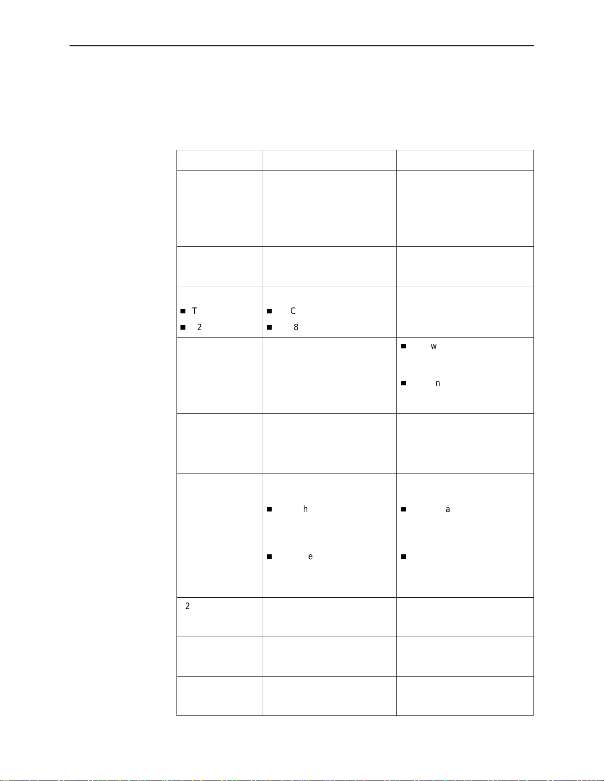
Consider the following before installing the GranDSLAM 4200:
Installation Site
Your installation site should be well ventilated, clean, and free of
environmental extremes.
Installation Options
The GranDSLAM 42 00 may be:
— Mounted with the included mounting brackets in a standard 19-inch
(483 mm) or 23-inch (584 m m) rack (including both Bay Networks and
Nortel 23-inch racks), or, with separately purchased mounting brackets, in
a 21-inch (535 mm) ETSI rack. ETSI brackets are available from
Paradyne. See Appendix B,
Equipment List
.
As many GranDSLAM 4200 units may be mounted in a standard rack as
there are 1.75-inch (44.45 mm) spaces in the rack, so long as adequate
cooling is provided.
— Mounted vertically against a wall.
The standard mounting brackets provided can be fastened to the base of
the unit for wall mounting.
— Set on a shelf or desktop.
Up to five GranDSLAM 4200 units may be stacked on a shelf or desktop.
Different models can be mixed in a stack.
Uplink Modules
Various uplink modules are available and one must be installed in each
GranDSLAM 4200. Any uplink module can be installed in any GranDSLAM
model. Your unit may have arrived from the factory with one of the following
uplink modules already installed:
— 4201 T1 Uplink Module
— 4202 E1 Uplink Module
— 4203 8-por t T1/E1 IMA Uplink Module
Power
The GranDSLAM 42 00 operates from a –48 VDC power supply (–40.5 to
–57.0 VDC) to allow for standard power connections available in a CO. For A C
voltage environments, an external AC-to-DC power converter is required.
Other Cabling
No cables are provided with the GranDSLAM 4200. See Table 1-2, Cable
Descriptions, to determine what cables you need to procure before
installation.
1-2
October 2002 4200-A2-GN20-10
Page 13
Cables Required
1. Installation
Table 1-2 shows all the cables that may be required for your installation.
Table 1-2. Cable Descriptions
Connector Name Connector and Cable For Connecting . . .
DSL PORTS 1–24
POTS 1–24
4201 T1 MODULE:
100Ω RJ48C
4202 E1 MODULE:
TX/RX 75Ω
120Ω
4203 T1/E1 IMA
MODULE
MGMT 8-position mo dular plug and
50-pin RJ21X Telco- type
straight connector and 50-wire
cable. Two cables required, one
for DSL and one for POTS (if
used).
BNC
RJ48C
RJ48C
8-wire Category 5 or better
unshielded twisted pair (UTP)
cable.
Up to 24 DSL ports to Main
Distribution Frame, punchdown
block, or spli tte r s.
Up to 24 POTS splitter ports to
Main Distribution Frame or
punchdown b lock.
A downstream
GranDSLAM 4200 to an
upstream ATM network.
A downstream
GranDSLAM 4200 to an
upstream ATM network.
A downstream
GranDSLAM 4200 to an
upstream ATM network.
A GranDSLAM 4200
aggregation unit to a basic
unit in a stack.
The GranDSLAM 4200 to a
Network Management System
over a Local Area Network ( LAN)
employing 10BaseT or
100BaseT.
CONSOLE DB9 plug connector and
shielded cable.
The other connector
depends o n the serial port on
your terminal or PC, but
normally is a DB9 socket.
The other connector
depends o n the serial port on
your modem, but normally is
a DB25 plug.
4210 ALARM 3-position termin al block and
3-wire shielded, twisted-pair
cable.
4220/4230 ALARM 5-position terminal block and
5-wire shielded, twisted pair
cable.
BITS (Building
Integrated Timing
Supply)
4200-A2-GN20-10 October 2002
Not applicable. For future use.
The GranDSLAM 4200 to one of
the following:
A terminal or a PC with a
terminal emulation program,
or
A modem.
The GranDSLAM 4200 to an
alarm system.
The GranDSLAM 4200 to an
alarm system.
1-3
Page 14

1. Installation
Unpack ing the Hardware
HANDLING PRECAUTIONS FOR
!
STATIC-SENSITIVE DEVICES
This product is designed t o protect s ensitive component s f rom damage
due to electrostatic discharge (ESD) during normal operation. When
performing installation procedures, however, take proper static control
precautions to prevent damage to equipment. If you are not sure of the
proper static control precautions, contact your nearest sales or service
representative.
The GranDSLAM 4200 is shipped in a cardboard shipping container. Carefully
remove the unit from its shipping container and check for physical damage. If the
unit shows signs of shipping damage, notify your sales representative.
Package Contents
In addition to this installation guide, the GranDSLAM 4200 shipping carton should
contain:
GranDSLAM 4200
Two sets of mounting bracke ts, one set suitable for a 19-inch (483 mm) rack
and one set suitable for a 23-inch (584 mm) rack (including Bay Networks and
Nortel)
Hardware kit (see Table 1-3, Contents of Hardware Kit Shipped with the
GranDSLAM 4200)
If anything is missing, notify your sales rep resenta tive.
Before installing the GranDSLAM 4200, read the
the beginning of this document.
Be sure to register your warranty at
www.paradyne.com/warranty
Important Safety Instructions
.
in
1-4
October 2002 4200-A2-GN20-10
Page 15
1. Installation
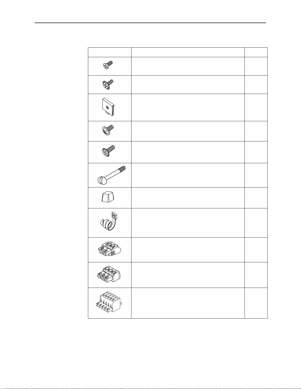
Table 1-3. Contents of Hardware Kit Shipped with the GranDSLAM 4200
Appearance Description Quantity
02-17259
02-17326
02-17256
02-17257
02-17258
02-17325
02-17261
Flat-head scr ew for attaching 19" mounti ng brackets to
unit
Machine screw with captiv e starwasher (6-32 x 1/4″) for
attaching 23" mou nti ng brackets to unit
Self-retaining nut for racks without threaded holes 5
Dress screw (12-24 x 1/2″) for use with self-retaining
nuts
Machine screw wit h captive starwashe r (10-32 x 1/2″)
for use with racks with threaded holes
Captive pan- head screw for replacing long T elco screw 3
Rubber foot for desk-mount and stacking of units 4
7
7
5
5
02-17262
02-17272
02-17273
02-17327
Cable tie (8″) for strain relief and cable management 3
2-position plug with screw flange for power connection 2
3-position plug for ALARM connection on Model 4210 2
5-position plug for ALARM connection on Model 4220
and Model 4230
2
4200-A2-GN20-10 October 2002
1-5
Page 16

1. Installation
Mounting Configurations
Three basic installation configurations are available:
Mounting Brackets
Your GranDSLAM 4200 can be installed in a rack or on the wall using mounting
brackets. Two brack ets suitable f or a 19-inch (483 mm) rack (marked EIA-19) and
two brackets suitable f or a 23-inch (584 mm) Bay Networks or Nortel rack (marked
with Paradyne Part Number 868-6282-0020) are shipped with the unit. Two
brackets suitable for a 21-inch (535 mm) rack (marked ETSI) are available from
Paradyne as a separate feature (see Appendix B,
Rack-mounting brackets may also be used to attach the unit to a wall.
Rack mount – see
Installing the Brackets for Rack Mounting
Installing the GranDSLAM 4200 Into a Rack
Wall mount – see
Shelf or desktop – see
Installing the GranDS LA M 4200 on a Wall
Installing the GranDSLAM 4200 on a Shelf or Desktop
on page 1-12.
NOTE:
In this guide, the term
for mounting telecommunications equipment.
refers to any rack, cabinet, frame, or bay suitable
rack
on page 1-8.
Equipment List
on page 1-6 and
on page 1-10.
).
Installing the Brackets for Rack Mounting
Procedure
To install the mounting brackets for rac k mounting:
1. Locate the black screw nearest the front panel on each side of the unit as
shown.
3
ALARMRTN -48VDC
.5
A
6
0
B
CONSOLE
A
POWER A
2. Remove these two black screws (one from each side) before attempting to
install the mounting brackets.
STATUS
UPLINK
B
BITS
MGMT
4
2
0
2
TX RX
TEST
ALRM
E1 MODULE
75Ω
120Ω
11
4
8
2
1
3
1
6
2
0
2
4
D
S
L
P
O
R
T
S
1
-
2
4
P
O
T
S
1
-
2
4
02-17274
1-6
October 2002 4200-A2-GN20-10
Page 17
1. Installation
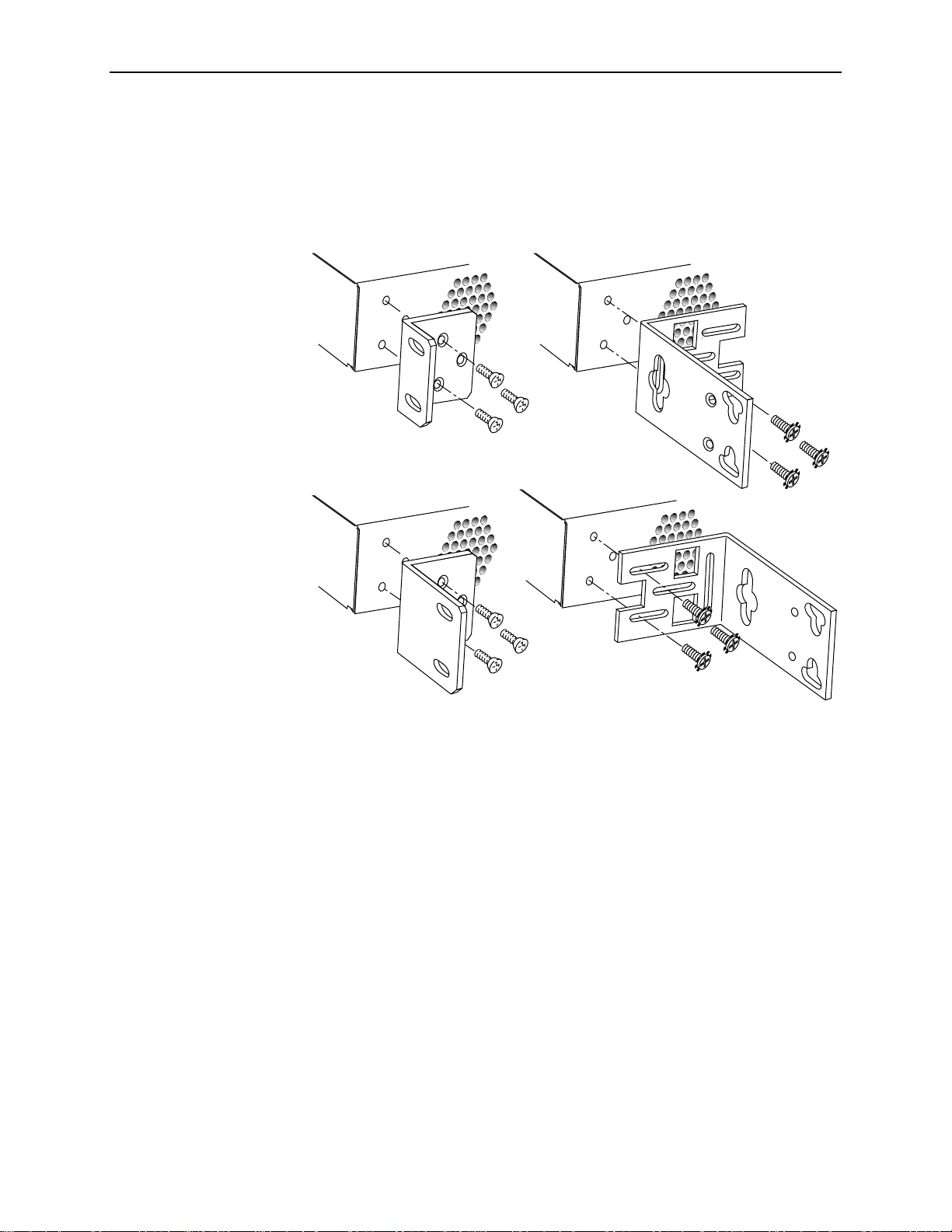
3. Identify six flat-head screws (for 19-inch racks) or six machine screw s (for
23-inch racks) provided with the moun ting brackets in the hardware kit.
4. Attach the brackets appropriate to your rack size. Tighten all screws firmly.
19-inch (483 mm) Rack Mount
23-inch (584 mm) EIA and Bay Networks
Rack Mount
21.1-inch (535 mm) Rack Mount
23-inch (584 mm) Nortel
Rack Mount
02-17324
4200-A2-GN20-10 October 2002
1-7
Page 18
1. Installation
Installing the GranDSLAM 4200 Into a Rack
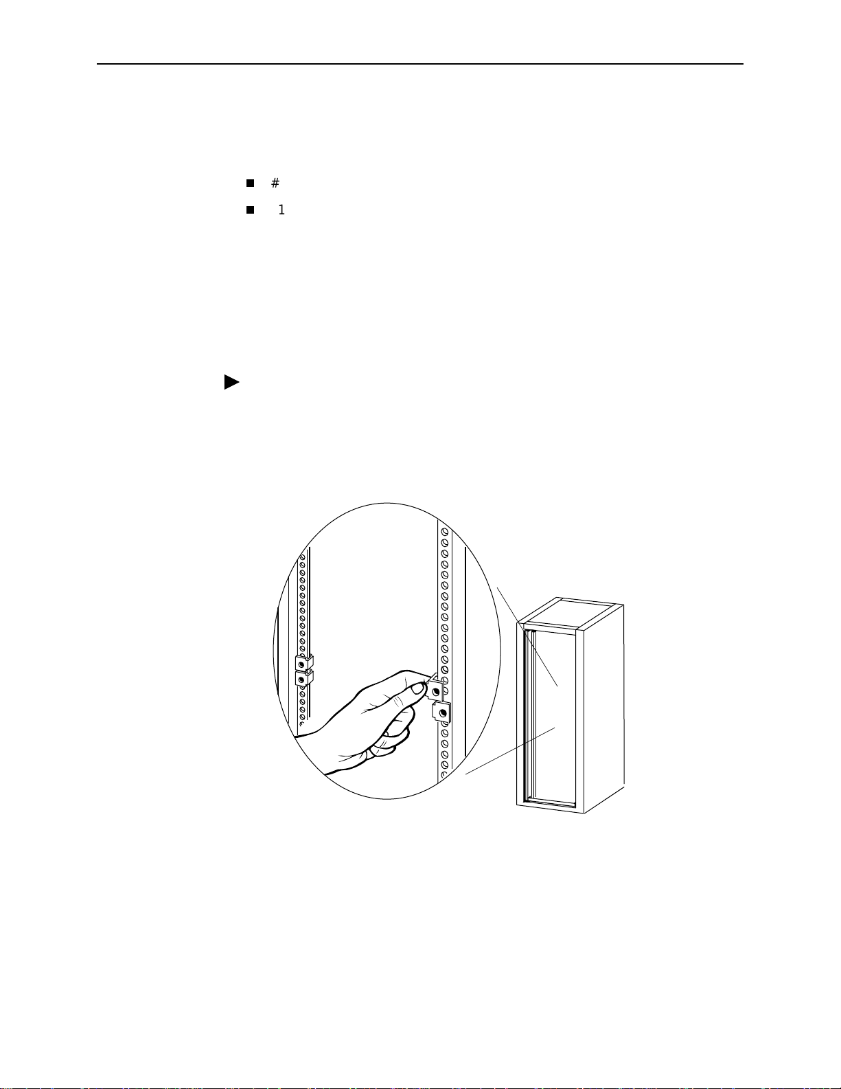
Two types of mounting screws are provided. Use:
#10-32 mounting screws for rails with threaded screw holes
#12-24 mounting screws and self-retaining nuts for rails with unthreaded
screw holes
NOTE:
Before installing the GranDSLAM 4200 in a rack or cabinet, you may prefer to
first attach the unit to a ground while you have unrestricted access to the
grounding lug on the side of the unit. See
for more inform ation.
Procedure
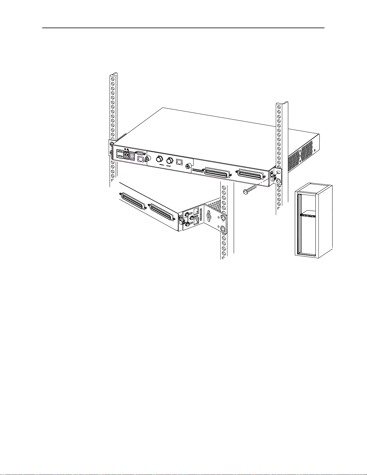
To install the GranDSLAM 4200 into a rack:
1. Determine where in the rack you will mount the GranDSLAM 4200. If your rack
does not have threaded screw holes, slip self-retaining nuts onto the rails
where the GranDSLAM 4200 will be fastened.
Grounding Lug
in Chapter 2,
Cabling
02-17070
2. Place the unit so that the brackets re st against the front of the rails. Insert
screws in the bottom screw positions and hand-tighten them.
1-8
October 2002 4200-A2-GN20-10
Page 19
1. Installation
23-inch (584 mm) Nortel
Rack Mount
11
2
1
3
2
4
D
S
L
P
O
R
T
S
1
-
2
4
P
O
T
S
1
2
4
48
1
6
2
0
P
O
W
E
R
A
A
L
A
R
M
R
T
N
-4
8
V
D
C
B
IT
S
M
G
M
T
C
O
N
S
O
L
E
S
T
A
T
U
S
U
P
L
I
N
K
A
L
R
M
T
E
S
T
B
A
3
.
5
A
6
0
B
E
1
M
O
D
U
L
E
4
2
0
2
T
XR
X
1
0
0
/1
2
0
W
7
5
W
1
1
2
1
3
2
4
D
S
L
P
O
R
T
S
1
-
2
4
P
O
T
S
1
2
4
4
2
1
0
4
8
1
6
2
0
P
O
W
E
R
A
A
L
A
R
M
R
T
N
4
8
V
D
C
B
I
T
S
M
G
M
T
C
O
N
S
O
L
E
S
T
A
T
U
S
U
P
L
I
N
K
A
L
R
M
T
E
S
T
B
A
3
.
5
A
6
0
B
T
1
/
E
1
M
O
D
U
L
E
4
2
0
1
T
X
R
X
1
0
0
/
1
2
0
W
7
5
W
3. Insert and tighten the screws in the top screw positions, then tighten the
botto m screw s.
4. Do not plug in the unit. Proceed to
Installing the Uplink Module
on page 1-13.
4200-A2-GN20-10 October 2002
1-9
Page 20
1. Installation
Installing the GranDSLAM 4200 on a Wall
Wall mounting requires two wood screws suitable for the weight of the fully cabled
unit. These are not included. Use at a minimum 1/4-inch (6 mm) diameter screws
in 3/4-inch (19 mm) plywood (not drywall).
Procedure
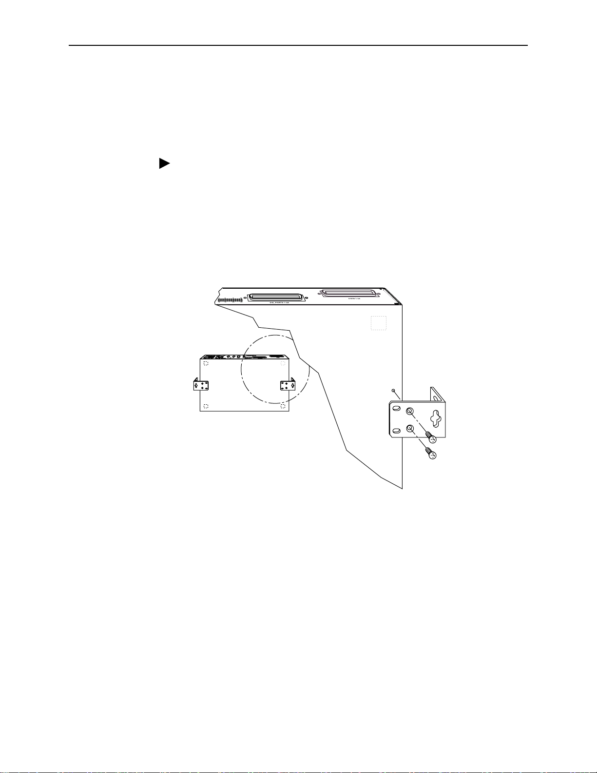
To install the GranDSLAM 4200 on a wall:
1. Identify the flat-head screws provided in the hardware kit and the brackets
suitable for a 19-inch rack. Two screws are required for each bracket.
2. Orient the unit so that the bottom is facing you and the faceplate is at the top.
3. Locate the supplied Right Side mounting bracket and fasten it to the right side
of the unit.
02-17252
4. Locate the supplied Left Side mounting bracket and fasten it to the left side of
the unit.
5. Tighten all screws firmly.
1-10
October 2002 4200-A2-GN20-10
Page 21
1. Installation
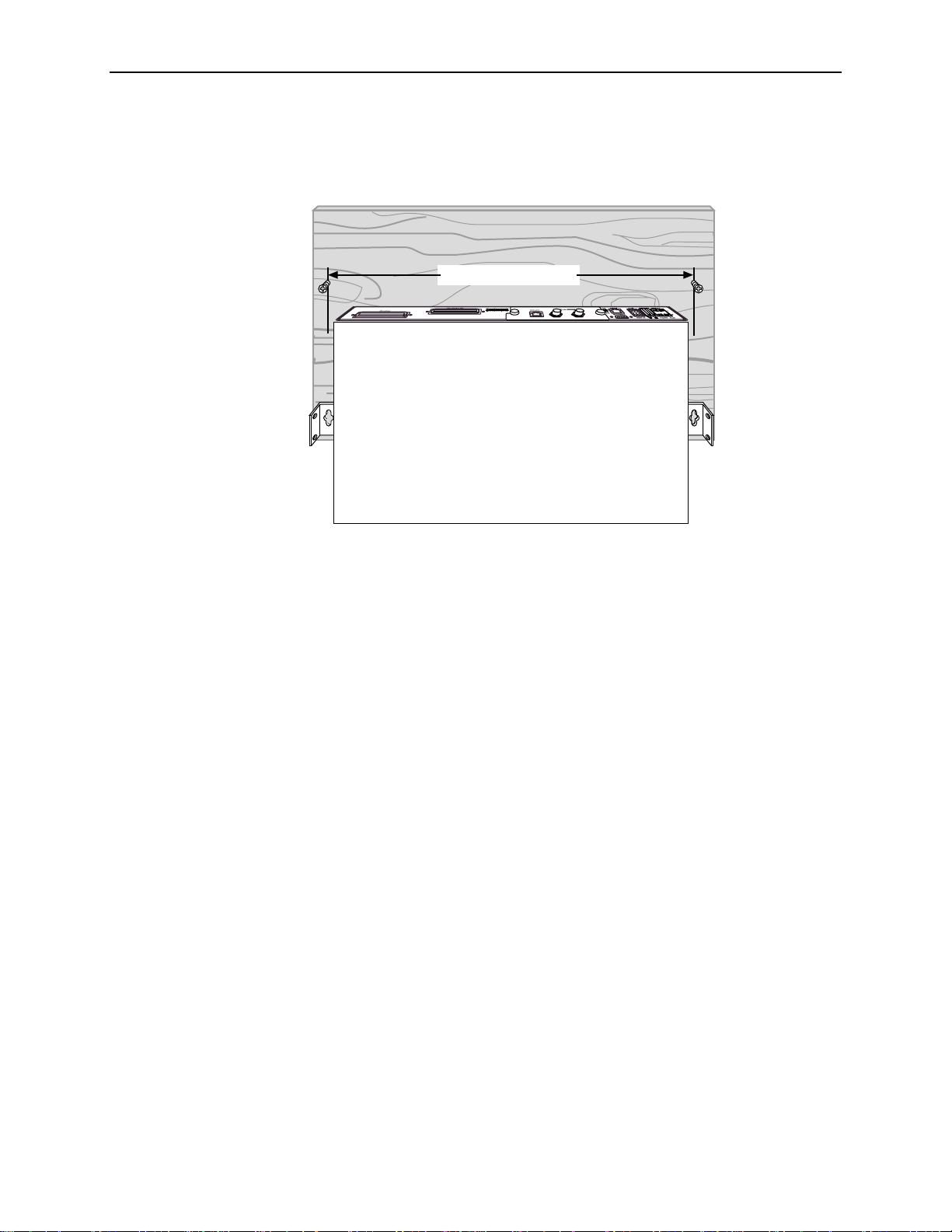
6. Install two wood screws (not provided) at the same height above the floor and
18.75 inches (476.25 mm) apart. Do not completely tighten the screws. Leav e
them so their heads are about 1/4 inch (6 mm) from the wall.
18.75 in (476.25 mm)
02-17254
7. Hang the unit from the wood screws to verify that the screws are properly
placed. The screws should freely slide into the top of the key slots in the
brackets.
8. Do not fasten the unit to the wall until after it is completely cabled and tested.
Proceed to
Installing the Uplink Module
on page 1-13.
4200-A2-GN20-10 October 2002
1-11
Page 22

1. Installation
Installing the GranDSLAM 4200 on a Shelf or Desktop
If the GranDSLAM 4200 will be placed on a shelf or desktop, install the provided
rubber feet befo re putting the unit in position.
Procedure
To install the GranDSLAM 4200 on a shelf or desktop, as a standalone unit or in a
stack:
1. Locate the rubber feet in the hardware kit provided with the unit.
2. Turn the unit upside down on a work surface. Squares stamped into the
bottom of the unit show the proper positions for the feet.
3. Remove the protective sheet from the bottom of each foot, then press the foot
onto a corner of the bottom of the unit.
4. Turn the unit right side up and place it in position on a shelf or desktop.
If the installation includes more than one unit, one can be stacked atop
another. Up to five units can be stacked together. If you intend to aggregate
the stack into a single uplink using the Model 4203 T1/E1 IMA Uplink Module,
the aggregation unit can be placed anywhere within the stack.
5. Do not plug in the unit. Proceed to
Installing the Uplink Module
on page 1-13.
02-17263
1-12
October 2002 4200-A2-GN20-10
Page 23

Installing the Uplink Module
Each GranDSLAM 4 200 requires an uplin k module for connection to the ATM
network. If your uplink module was shipped separately from the
GranDSLAM 4200, install the uplink module before you connect the unit to a
power source. If your GranDSLAM 4200 arrived with an uplink module already
installed, proceed to Chapter 2,
NOTE:
The uplink modules are hot sw appable. If you install an uplink module after the
unit has already been powered-on, reset the unit before attempting to operate
it.
HANDLING PRECAUTIONS FOR
!
STATIC-SENSITIVE DEVICES
This product is designed t o protect s ensitive component s f rom damage
due to electrostatic discharge (ESD) during normal operation. When
performing installation procedures, however, take proper static control
precautions to prevent damage to equipment. If you are not sure of the
proper static control precautions, contact your nearest sales or service
representative.
Cabling
1. Installation
.
Procedure
To install the uplink module:
1. Remove the two captive screws holding the blank filler panel on the
GranDSLAM 4200.
R
T
N
-
4
8
V
D
C
3
A
.5
A
L
A
6
R
0
B
A
P
2. Store the blank filler panel and screws for possible future use.
M
C
O
N
S
O
L
O
W
E
R
A
B
E
STATUS
B
IT
UPLINK
S
M
G
M
T
TEST
ALRM
11
48
2
1
3
1
6
2
0
2
4
02-17264
4200-A2-GN20-10 October 2002
1-13
Page 24

1. Installation
3. Slide the uplink module into the guide rails just inside the opening. Press the
uplink module firmly into place until it is fully seated and the faceplate of the
uplink module is flush against the faceplate of the GranDSLAM 4200.
R
T
N
-
4
8
V
D
C
3
A
.5
A
L
A
6
R
0
B
A
P
M
C
O
N
S
O
L
O
W
E
R
A
B
E
STATUS
B
I
T
UPLINK
S
M
G
M
T
TEST
ALRM
11
48
4202
T
X
E
1 M
O
DU
LE
R
X
75
Ω
100/120
Ω
2
1
3
1
6
2
0
2
4
02-17267
4. Fasten the two screws provided with the uplink module.
Do not plug in the unit. Proceed to Chapter 2,
Cabling
.
1-14
October 2002 4200-A2-GN20-10
Page 25

Cabling
Cabling Overview
The GranDSLAM 4200 has a large variety of possible cabling configurations. This
chapter describes all possible connections, not all of which are required:
2
DSL Ports
4201 T1 Uplink Module Connector
4202 E1 Uplink Module Connectors
4203 T1/E1 IMA Uplink Module Port Connectors
Console Port
Alarm Interface
Grounding Lug
Po wer Connector
on page 2-2
on page 2-3
on page 2-4
on page 2-10
on page 2-12
on page 2-15
on page 2-16
on page 2-6
4200-A2-GN20-10 October 2002
2-1
Page 26

2. Cabling
DSL Ports
The GranDSLAM 4200 DSL connector supports the tip and ring connections of up
to 24 DSL por ts over a 50-position cable. A POTS (plain old telephone serv ice)
splitter connector is also provided. If your model does not contain the integrated
POTS splitter, you must connect the unit to a separate POTS splitter.
Procedure
To cable the DSL Por ts:
1. Insert a cable tie (provided) through the top of the anchor mount next to the
DSL PORTS 1–24 connector.
2. If the connector for your cable has a short captive screw, attach the cable to
the DSL PORTS 1–24 connector and fasten it to the jack screw with its short
captive screw.
#4-40
Jack Screw
Short
Screw
50-Pin
Connector
Anchor
Mount
02-17083
3. If the connector for your cable has a long captive screw, remove the provided
jack screw from the threade d hole next to the DSL PORTS 1–24 connector.
Attach the DSL PORTS 1–24 connector to the unit using the long, captive
pan-head screw (provided).
Anchor
Mount
Long
Screw
50-Pin
Connector
02-17346
4. Tighten the cable tie around the connector and trim the excess.
02-17084
5. If using an integrated POTS splitter, the POTS 1–24 connector is used.
Repeat Step 1 through Step 4, substituting PO TS 1–24 for DSL PORTS 1–24.
6. Secure the cables as required for strain relief.
2-2
October 2002 4200-A2-GN20-10
Page 27

Uplink Module Connectors
The following types of up link modules are available for the unit:
Model 4201 T1 Uplink Module
Model 4202 E1 Uplink Module
Model 4203 T1/E1 IMA Uplink Module
4201 T1 Uplink Module Connector
The 4201 T1 Uplink Module has a single RJ48C, 8-pin, unkeyed, shielded
connector.
NOTE:
The metal shell of the T1 connector is grounded. Pins 7 and 8 of the connector
are not grounded. Therefore, if the cable you are using is wired to ground the
cable shield to pins 7 and 8, you must first obtain a cable with a shielded plug
and connect the cable shields (drain wires) to the plug’s shield. If yo u r cab le
has separate shields for transmit and receive, you must ground both drain
wires. You can also ground the shields at the far end, or you can use a
nonshielded cable.
2. Cabling
Procedure
To connect to the 4201 T1 Uplink Module:
1. Determine the interface type, and procure the appropriate cable.
2. Plug the 8-position modular plug into the 100Ω modular jack.
R
T
N
-4
8
V
D
C
3.5 A
A
L
A
60
R
B
A
P
O
W
E
R
M
C
O
N
S
O
L
E
S
K
U
T
IN
A
L
T
P
S
A
B
B
IT
S
U
M
T
M
420
G
M
S
R
T
1
L
E
T
A
T
1
M
O
D
U
L
E
1
0
0
Ω
8-Position
Modular
Plug
11
48
1
2
3
1
6
2
0
2
4
02-17275
3. Connect the other end of the cable to the appropriate network equipment such
as a multiplexer .
4200-A2-GN20-10 October 2002
2-3
Page 28

2. Cabling
4202 E1 Uplink Module Connectors
The 4202 E1 Uplink Module has two connectors, only one of which may be used at
a time:
120Ω connector – A balanced RJ48C, 8-pin, unkeyed, unshielded connec tor.
The 120Ω connector is the default.
75Ω connector – An unbalanced BNC connector with two jacks (TX/RX). To
use the 75Ω connector, you must change the default using the TL1
commands. For more information on TL1 commands, see the
GranDSLAM 4200 ATM Stackable DSLAM User’s Guide
NOTE:
The metal shell of the T1 connector is grounded. Pins 7 and 8 of the connector
are not grounded. Therefore, if the cable you are using is wired to connect its
shield to pins 7 and 8, then the cable’s shield will not be grounded at the
module end. To ground the cable shield at the module end, you must use a
cable with a shielded plug and the cable shields (drain wires) must be
connected to the plug’s shield. If your cable has separate shields for transmit
and receive, you must ground both drain wires. You can also ground the
shields at the far end, or you can use a nonshielded cable.
.
Procedure
To connect to the 4202 E1 Uplink Module 120Ω connector:
1. Determine the interface type, and procure the appropriate cable.
2. Plug the 8-position modular plug into the 120Ω modular jack.
CAUTION:
Do not plug cables into both the 120Ω and the 75Ω connectors at the
same time.
R
T
N
-4
8
V
D
C
3.5 A
A
L
A
60
R
B
A
P
O
W
E
R
M
C
O
N
S
O
L
E
S
K
U
T
IN
A
L
T
P
S
A
B
B
IT
S
U
M
T
M
4202
G
M
S
R
T
L
E
T
A
E
1
T
M
X
O
D
U
L
E
R
X
7
5
Ω
1
2
0
Ω
11
48
1
3
1
6
8-Position
Modular
Plug
2
2
0
2
4
02-17276
2-4
October 2002 4200-A2-GN20-10
Page 29

2. Cabling
3. Connect the other end of the cable to the appropriate network equipment such
as a multiplexer .
Procedure
To connect to the 4202 E1 Uplink Module 75Ω connector:
1. Determine the interface type, and procure the appropriate coaxial cable.
2. Change the connector default to 75Ω using the
command (
LINETYPE=G703SHORT75
).
ENT-T1
or
ED-T1
TL1
3. Plug the TX coaxial cable into the TX 75Ω jack.
4. Plug the RX coaxial cable into the TX 75Ω jack.
CAUTION:
Do not plug cables into both the 120Ω and the 75Ω connectors at the
same time.
R
T
N
-4
8
V
D
C
3.5 A
A
L
A
60
R
B
A
P
O
W
E
R
M
C
O
N
S
O
L
E
S
K
U
T
IN
A
L
T
P
S
A
B
B
IT
S
U
M
T
M
4202
G
M
R
T
L
ES
T
A
E
1
T
M
X
O
D
U
L
E
R
X
7
5
Ω
1
2
0
Ω
112
48
1
3
1
6
2
0
2
4
5. Connect the other end of the cables to the appropriate network equipment
such as a multiplexer.
4200-A2-GN20-10 October 2002
Coaxial
Cable
02-17277
2-5
Page 30

2. Cabling
4203 T1/E1 IMA Uplink Module Port Connectors
The 4203 T1/E1 IMA Uplink Module suppor t s eight operational T1/E1 ports, each
with an RJ48C, 8-pin, unkeyed, shielded connector. The 4203 uplink module can
be used to aggregate up to four other G ranDSLAM 4200 units subtende d in a
stack, allowing up to 120 ports in the stack to be managed with a single
Permanent Virtual Circuit (PVC).
NOTE:
The metal shell of the T1/E1 connector is grounded. Pins 7 and 8 of the
connector are not grounded. Therefore, if the cable you are using is wired to
ground the cable shield to pins 7 and 8, you must first obtain a cable with a
shielded plug and connect the cable shields (drain wires) to the plug’s shield. If
your cable has separate shields for transmit and receive, you must ground
both drain wires. You can also ground the shields at the far end, or you can
use a nonshielded cable.
Procedure
To connect to the 4203 T1/E1 IMA Uplink Module:
1. Determine the interface type, and procure the appropriate cable.
2. Plug up to eight 8-position modular plugs into the ports labeled 1–8.
If this is the aggregation unit in a stack, the unit defaults to using ports 1–4 as
the uplink ports. This default can be changed using the
command. See the
GranDSLAM 4200 ATM Stackable DSLAM User’s Guide
ENT-VCL
TL1
for more infor m ation on subtend ing and TL1 com ma nds.
R
TN
-48V
D
C
3.5 A
60
A
B
A
P
O
W
E
R
LA
R
M
C
O
N
S
O
LE
S
K
U
T
IN
A
L
T
P
S
A
B
B
IT
S
U
M
M
T
G
4203
M
S
R
T
L
E
T
A
T1/E1 MODULE
1234
5678
112
48
13 24
16 20
8-Position
Modular
Plug
02-17332
3. Install the required ferrite choke on all the DSL cables connected to the 4203
T1/E1 IMA Uplink Module (see
Cable Ferrite Choke
on page 2-8).
Installing the 4203 T1/E1 IMA Uplink DSL
2-6
October 2002 4200-A2-GN20-10
Page 31

2. Cabling
4. Connect the other end of the cable(s) to the appropriate network equipment
such as an ATM switch.
Or, if this is the aggregation unit in a stack, connect to one of the following
connectors on a basic unit in the stack:
— 100Ω connector on a 4201 T1 Module
— 120Ω connector on a 4202 E1 Module
— 100Ω/120Ω connector 5–8 on a 4203 T1/E1 IMA Module.
R
T
N
-4
8
V
D
C
3.5 A
A
L
A
60
R
E
R
A
B
8
V
D
C
3.5 A
60
E
R
A
B
8
V
D
C
3.5 A
60
E
R
A
B
C
3.5 A
60
A
B
To
AT M
Switch
M
C
O
N
S
O
L
E
S
K
U
T
IN
A
L
T
P
S
B
IT
S
A
L
A
R
B
IT
S
A
L
A
R
B
IT
S
A
L
A
R
M
B
IT
S
U
M
T
M
4
G
202
M
S
R
T
L
E
T
A
M
C
O
N
S
O
L
E
S
K
U
T
IN
A
L
T
P
S
U
M
T
M
G
M
S
R
T
L
E
T
A
M
C
O
N
S
O
L
E
S
K
U
N
T
I
A
L
T
P
S
U
M
T
M
G
M
S
R
T
L
E
T
A
C
O
N
S
O
L
E
S
K
U
N
T
I
A
L
T
P
S
U
M
T
M
G
M
S
R
T
L
E
T
A
E
1
M
O
D
U
420
2
E
1
M
O
D
U
4
202
E
1
M
O
D
U
4203
T
1
/E
1
M
O
T
XR
L
E
T
XR
L
E
T
XR
L
E
1234
D
U
L
E
56
X
7
5
W
1
2
0
W
112
48
13 24
16 20
X
7
5
W
1
2
0
W
112
48
13 24
16 20
X
7
5
W
1
2
0
W
112
4
8
13 24
16 20
112
78
48
13 24
16 20
02-17333
B
A
P
O
W
R
T
N
-4
B
A
P
O
W
R
T
N
-4
B
A
P
O
W
R
T
N
-4
8
V
D
B
A
P
O
W
E
R
4200-A2-GN20-10 October 2002
2-7
Page 32

2. Cabling
Installing the 4203 T1/E1 IMA Uplink DSL Cable Ferrite Choke
The 4203 T1/E1 IMA Uplink is shipped with a ferrite choke that must be installed
on the DSL cable(s). One choke can accommodate 1–8 cables.
Procedure
To install the ferrite choke onto the DSL cable(s):
1. Open the ferrite choke and place it around the cable(s) as clos e to the cable
connector on the uplink module as possible.
2. Close the two halves around the cable and snap the choke shut, pressing
down on the plastic latch to secure it.
3. To prevent the ferrite choke from slipping down the cable, install a tie wrap
behind the ferrite choke as shown.
Tie
Wrap
Plastic
Latch
02-17334
2-8
October 2002 4200-A2-GN20-10
Page 33

Management Port
The MGMT (management) port can be used to connect the GranDSLAM 4200 to a
network management system using a 10Ba seT or 100Ba seT LAN . The MGMT
port is isolated and no user data is accessible over it. A straight-through cable is
used.
Procedure
To use the MGMT port:
1. Connect a modular 8-pin cable to the MGMT port.
2. If the GranDSLAM 4200 is in a rack, fasten the cable to a rail with a cable tie.
3. Connect the other end of the cable to your Ethernet hub or to a network
2. Cabling
interface card in a PC.
Hub Device
R
T
N
-4
8
V
D
C
3.5 A
A
L
A
60
R
B
A
P
O
W
M
C
O
N
S
O
L
E
S
K
U
N
T
I
A
L
T
E
R
A
B
B
IT
P
S
U
S
M
T
M
4202
G
M
S
R
T
L
E
T
A
MGMT
E
1
M
Por t
T
X
O
D
U
L
E
R
X
7
5
W
1
2
0
W
112
48
13 24
16 20
02-17278
4200-A2-GN20-10 October 2002
2-9
Page 34

2. Cabling
Console Port
The CONSOLE port normally serves as the primary user interface with the
GranDSLAM 4200 during installation. Y ou can connect a terminal or PC directly to
the CONSOLE port using a DTE cable (see procedure below). You can also use
the CONSOLE port to attach a modem to the GranDSLAM 4200 for remote dial-in
management of the unit using a DCE cable (see procedure on next page).
Procedure
To connect a terminal or PC to the CONSOLE por t:
1. Configure the terminal or terminal emulation program to use the following
parameters:
— Maximum speed: 9600 bps
— Data bits: 8
— Parity: None
— Flow Control: None
— Stop bits: 1
2. Determine and procure the proper Data Terminal Equipment (DTE) cable type.
The CONSOLE port requires a DB9 plug connector. The other connector
depends on the serial port on your terminal or PC.
3. Connect the DB9 plug connector to the CONSOLE port socket. The
CONSOLE port is ordinarily used only during installation, so do not fasten the
connector.
4. Connect the other end of the cable to the serial port of your terminal or PC.
Serial
Por t
R
T
N
-
4
8
V
D
C
3
A
.
5
L
A
A
R
6
0
M
B
A
P
O
W
C
O
N
S
O
L
E
S
K
U
N
T
I
A
L
T
E
R
A
B
P
S
U
B
IT
S
M
M
T
G
M
S
R
T
L
E
T
A
4
2
0
2
E
1
M
O
D
U
L
CONSOLE
T
X
E
7
5
W
R
X
Por t
1
0
0
/1
2
0
W
11
48
2
1
3
1
6
2
0
2
4
D
S
L
P
O
R
T
S
1
-
2
4
02-17271
2-10
October 2002 4200-A2-GN20-10
Page 35

2. Cabling
Procedure
To connect a modem to the CONSOLE port:
1. Determine and procure the proper DCE cable type. The CONSOLE port
requires a DB9 plug connector. The other connector depends on the serial
port on your modem, but normally a DB25 plug is required.
2. Connect the DB9 plug connector to the CONSOLE port socket.
3. If the modem will be permanently connected, fasten the connector to the
Management Module with its captive screws. If the GranDSLAM 4200 is in a
rack, dress the cable to the left and attach it to the rail with a cable tie.
4. Connect the other end of the cable to the serial port of your modem.
Serial Port
P
W
R
A
L
M
T
S
T
L
I
N
E
E
T
H
E
R
N
E
T
R
T
N
-4
8
V
D
C
3.5 A
A
L
A
60
R
B
A
P
O
W
M
C
O
N
S
O
L
E
S
K
U
N
T
I
A
L
T
E
R
A
B
B
IT
S
P
S
U
M
T
M
4
G
202
M
S
R
T
L
E
T
A
T
X
E
1
M
O
D
U
L
E
R
X
7
5
W
1
2
0
W
CONSOLE
Por t
Modem
112
48
13 24
16 20
02-17279
4200-A2-GN20-10 October 2002
2-11
Page 36

2. Cabling
Alar m I nterface
The alarm interface differs, depending on GranDSLAM 4200 model.
Model 4210 – The ALARM interface for the Model 4210 consists of three
contacts that provide access to to the alarm relays that can be used to set off
Major and Minor physical alarms. A 3-position plug provided in the Model 4210
hardware kit is used to connect 16–28 AWG wire to the ALARM terminal block
(see Table 1-3, Contents of Hardware Kit Shipped with t he GranDSLAM 4200,
in Chapter 1,
Models 4220 and 4230 – The ALARM interface for the Models 4220 and 4230
Installation
).
consists of five co ntacts. Three of the contacts provide access to alarm relays
that that can be used to set off Major and Minor physical alarms. The other two
contacts provide access to a sense circuit that can be used to detect the open
or closed condition of an external alarm relay. See Figure 2-1, Alarm
Connection Example, for an example of how to connect a Model 4220 to a
Model 4210 so that the Model 4220 can monitor the state (open/closed) of the
Model 4210’s major alarm.
A 5-position plug provided in the Model 4220 and Model 4230 hardware kit is
used to connect 20–28 AWG wire to the ALARM terminal block (see Table 1-3,
Contents of Hardware Kit Shipped with the GranDSLAM 4200, in Chapter 1,
Installation
).
CAUTION:
The ALARM Sense + and Sense – contacts are intended to be connected
to an external alarm relay . Do not apply power to these contacts; doing so
will result in damage to the unit.
Minor Common Major
ALARM
Model 4210
To Alarm
Monitoring
System
ALARM
Model 4220
BITS
Sense Sense+ Minor Common Major
02-17331
Figure 2-1. Alarm Connection Example
2-12
October 2002 4200-A2-GN20-10
Page 37

2. Cabling
Procedure
To connect the ALARM interface:
1. Strip the tips of the alarm source wires (about 1/2 inch or 12.7 mm in length).
2. For Model 4210, insert the wires into the 3-position plug. Securely fasten each
wire by tightening the screw above it.
For Models 4220/4230, use a screwdriver to press the orange spring tab in
while inserting the wire into the hole below it.
NOTE:
For all models, the insulation sho uld be fully within the plug and no bare
wire should be exposed outside of the plug.
Spring
Ta b
02-17283
02-17328
3. Insert the plug into the ALARM interface on the front panel of the
GranDSLAM 4200.
4. If the GranDSLAM 4200 is in a rack, dress the cable to the left and secure it to
the rail with a cable tie.
4200-A2-GN20-10 October 2002
2-13
Page 38

2. Cabling
5. Connect the other end of the cable to your alarm monitoring system.
CO Alarm
Monitoring System
R
T
N
-4
8V
D
C
3.5 A
A
L
A
60
R
B
A
P
O
W
M
C
O
N
S
O
L
E
S
K
U
N
T
I
A
L
T
E
R
A
B
B
IT
S
P
S
U
M
T
M
42
G
M
S
R
02
T
L
E
T
A
T
X
E
1
M
O
D
U
L
E
R
X
7
5
W
1
2
0
W
Model 4210
112
48
13 24
16 20
02-17280
Or, for Models 4220 and 4230, you can connect the other end of the cable to
an alarm interface on another GranDSLAM 4200 unit so that alarm conditions
on both units can be reported through one GranDSLAM 4200.
CO Alarm
Monitoring System
R
T
N
-4
8
V
D
C
3.5 A
A
L
A
60
R
B
A
P
O
W
R
T
N
-4
8
V
D
B
A
P
O
W
E
R
M
C
O
N
S
O
L
E
S
K
U
N
T
I
A
L
T
E
R
A
B
B
IT
S
C
3.5 A
60
A
L
A
R
M
A
B
B
IT
S
P
S
U
M
T
M
420
G
M
S
R
T
2
L
A
C
O
N
S
O
L
E
S
K
U
N
T
I
A
L
T
P
S
U
M
T
M
G
M
S
R
T
L
E
T
A
T
E
T
X
E
1
M
O
D
U
L
E
4203
T
1
/E
1
M
O
D
U
L
E
R
X
7
5
W
1
2
0
W
1234
5678
112
4
8
13 24
16 20
Model 4220/4230
112
48
13 24
16 20
Model 4210
02-17329
2-14
October 2002 4200-A2-GN20-10
Page 39

Grounding Lug
2. Cabling
Procedure
To connect the unit to a ground:
1. Strip back the insulation approximately 5/16 of an inch (8 mm) on 14 AWG
copper ground wire.
2. Loosen the screw on the grounding lug located on the side panel near the
front of the unit.
3. Insert the stripped end of the wire through the bottom of the grounding lug and
tighten the screw. Ensure that the screw makes contact with the stripped
portion of the wire.
4. Attach the ground wire to an earth ground.
R
T
N
-
4
8
V
D
C
3
A
.
5
L
A
A
R
6
0
M
B
A
P
O
W
C
O
N
S
O
L
E
S
K
U
N
T
I
A
L
T
E
R
A
B
P
S
U
B
IT
S
M
M
T
4
G
2
0
M
S
R
2
T
T
X
L
E
T
A
E
1
M
O
D
U
R
L
X
E
7
5
Ω
1
2
0
Ω
11
48
2
1
3
1
6
2
0
2
4
D
S
L
P
O
R
T
S
1
-
2
4
P
O
T
S
1
-
2
4
02-17270
4200-A2-GN20-10 October 2002
2-15
Page 40

2. Cabling
Power Connector
The GranDSLAM 4200 is powered by a –48 VDC source providing –40.5 to
–57.0 VDC. Dual power feeds are provided (A and B) for redundancy. The
terminal block accepts 16 or 18 AWG wire.
The 4200 GranDSLAM con tains two external fuses, each with a visual spring
indicator and an alarm circuit indicator in case the fuse is blown.
Procedure
To supply –48 VDC power to the GranDSLAM 4200 from a single –48 VDC power
source:
CAUTION:
Make sure that the DC power source wires are not powered (that is, the
circuit breakers or fuses are open at the source).
1. Strip the tips of the power source wires (about 1/2 inch or 12.7 mm in length)
before inserting the wire into the 2-position plug.
2. Insert the wires into the supplied 2-position plug with screw flange and
securely fasten each wire by tightening the screw above it. The insulation
should be fully within the plug and no bare wire should be exposed outside of
the plug.
NOTE:
You should clearly label these power source wires as –48V and RTN
respectively.
RTN
–48VDC
02-17283
2-16
October 2002 4200-A2-GN20-10
Page 41

2. Cabling
3. Insert the plug into either the A or B power input terminal on the front panel of
the GranDSLAM 4200.
Insert the . . . Into the . . .
Negative side of the power source –
Posi ti ve side of the power source
R
T
N
-4
8
V
D
C
3.5 A
A
L
A
60
B
A
P
O
W
E
R
R
A
B
B
IT
48VDC
input terminal.
RTN
(return) terminal.
M
C
O
N
S
O
L
E
S
K
TU
IN
A
L
T
P
S
S
U
M
T
M
4202
G
M
S
R
T
L
E
T
A
E
1
T
M
X
O
D
U
L
E
R
X
7
5
Ω
1
2
0
Ω
02-17282
4. If the unit is in a rack, dress the pow er cab les to t he left and fasten them to the
rail with a cable tie.
5. Power on the GranDSLAM 4200.
6. Make sure the STATUS LED on the front panel is ON (green). See Chapter 3,
.
LEDs
4200-A2-GN20-10 October 2002
2-17
Page 42

2. Cabling
2-18
October 2002 4200-A2-GN20-10
Page 43

LEDs
LED Locations
3
The locations of the System and DSL Port LEDs on the front panel of the
GranDSLAM 4200 are shown in Figure 3-1, Front Panel LEDs.
R
T
N
4
8
V
D
C
3
A
.
5
L
A
A
6
R
0
M
B
C
A
O
N
S
O
L
E
S
K
U
T
IN
A
L
P
O
T
W
P
E
R
S
U
A
B
B
I
T
S
M
M
T
4
G
2
M
S
R
0
T
2
T
L
E
X
T
A
E
1
M
O
D
U
L
R
E
X
7
5
Ω
1
2
0
Ω
1
4
8
1
2
1
3
1
6
2
0
2
4
D
S
L
P
O
R
T
S
1
-
2
4
P
O
T
S
1
2
4
CONSOLE
UPLINK
MGMT
STATUS
ALRM
TEST
4202
E1 MODULE
TX RX
75Ω
120Ω
112
48
13 24
16 20
System LEDs DSL Port LEDs
Figure 3-1. Front Panel LEDs
DSL PORTS 1-24
02-17266
4200-A2-GN20-10 October 2002
3-1
Page 44

3. LEDs
LED Meanings
When power is first applied to the unit, it performs a power-on self-test. When this
test is successfully completed, the Status LED blinks. The meaning of all the LEDs
is shown in Table 3-1, Front Panel LEDs.
Table 3-1. Fron t Panel LEDs
LED Color State Meaning
ALARM Amber Off
On
Blinking
DSL Port
(1–24)
STATUS Green Off
TEST Amber Off
UPLINK
1
1
For an IMA group connection, the UPLINK LED goes off when that group
connection is down. Ho we ve r , if any link i n the group goes down, the UPLINK LED
blinks.
Green Off
On
Blinking
On
Blinking
On
Green Off
On
Blinking
No Alarms.
At least one major or critical alarm has been
detected.
At least one minor or automatic message alarm
has been detected. No major or cri ti cal alarms
have been detected.
The port is disabled or no signal is detected on
the line.
The port has successf ully tr ai ned wit h the r emote
and is active .
The port is attempting to trai n.
No power.
The unit has power and has completed
initializ ati on and the self-test.
Normal operation.
Normal operating mode . No dis ruptive tests are
active in t he system.
At least one disruptive test is active in the
system.
The link is disabled, or no physical connect ion
exists.
The link is up.
An ATM alarm is occuring on the uplink.
3-2
October 2002 4200-A2-GN20-10
Page 45

Configuration
Overview
The GranDSLAM 4200 is designed to require minimal configuration before it can
be accessed by a Network Operations Center (NOC).
Initial configuration can be performed using the Command Line Interface (CLI).
The CLI is available from a terminal or PC connected to the CONSOLE port.
Additional configuration may be necessary, depending on the mode used to
manage the GranDSLAM 4200:
4
Inband management (managing via a PVC from the NOC).
Conventions Used
Managing out of band through the Ethernet port.
Additional configuration is also necessary if you do not choose to accept the
defaults that have been automat ically assigned to your GranDSLAM 4200. For
more configuration information, see the
User’s Guide .
In this book, the Enter key means what ever key you use to submit data to your
terminal or PC. It may be called the Return key on older devices.
Characters displayed on your screen, including those you type, are shown in the
Courier
font in this book .
GranDSLAM 4200 A TM Stackabl e DSLAM
4200-A2-GN20-10 October 2002
4-1
Page 46

4. Configurati on
Using the CLI
The GranDSLAM 42 00 uses Transaction Langu age No. 1 (TL1) language for CLI
commands and messages. These commands and m es sages are used to
configure and maintain the system. See the
DSLAM User’s Guide
for detailed infor m ation about the CLI.
GranDSLAM 4200 ATM Stackable
TL1 offers the following features to help you with command entry:
Automatic command completion.
You need to type only enough of a
command to make it unique, then type a question mark (?) and the CLI then
completes the command.
For exampl e, if you enter:
RTRV-H
the CLI expands it to:
RTRV-HDR:[TID]::[CTAG];
Automatic completion of optional fields.
Pressing the Tab key while
entering a command causes the CLI to fill in the optional fields.
For exampl e, enter:
RTRV-HDR
Press the Tab key, the CLI fills in the TID:
RTRV-HDR:TL1-Agent
Press the Tab key twice again, the CLI fills in the delimiters:
RTRV-HDR:TL1-Agent::
Press the Tab key again, the CLI fills in the CTAG:
RTRV-HDR:TL1-Agent::100
Keep pressing the Tab key to fill in the rest of the comm and delim it er s:
RTRV-HDR:TL1-Agent::100::;
Comma nd l ist i ng .
If you begin typing a command, then press the Tab ke y, the
CLI cycles through all the commands that contain the characters you have just
typed.
For exampl e, enter:
RTRV-PROFILE
Press the Tab key, the CLI displays:
RTRV-PROFILE-ADSLALM
Press the Tab key again, the CLI displays:
RTRV-PROFILE-ADSLDNALM
Press the Tab key again, the CLI displays:
RTRV-PROFILE-ADSLDN
4-2
October 2002 4200-A2-GN20-10
Page 47

4. Configuration
Command query.
You can obtain help with CLI commands by typing a ?
(question mark). A question mark alone lists all commands.
For exampl e, if you enter:
RTRV ?
the CLI lists all the possible RTRV commands.
Comman d hi st ory.
Pressing the Up Arrow key while entering a comm and
returns the CLI to the previous command entry.
RTRV-META command.
Retrieves all commands.
GranDSLAM 4200 Turn-up Procedure
You can turn up your GranDSLAM 4200 through the Ethernet connection via a PC
or terminal connected to the unit’s CONSOLE port. Then, using a series of TL1
commands or an NMS system such as Paradyne’s GrandVIEW Element
Management System (EMS), you configure the unit for operation.
The turn-up procedure for the GranDSLAM 4200 system differs, depending on the
type of management used:
Inband Management – Operates over the ATM interf ace. This is the default for
the GranDSLAM 4200.
Out-of-Band Management – Operates over the Ethernet interface.
The turn-up procedure for both management types also differs, depending on
whether you are in Manual mode (no DHCP server), or in DHCP (BOOTP) mode
using a DHCP server.
Manual Mode – If a DHCP server is not being used, you must manually assign
an IP address to your GranDSLAM 4200.
DHCP Mode – If you are using a DHCP server, you do not need manually
assign an IP address since this is done automatically.
4200-A2-GN20-10 October 2002
4-3
Page 48

4. Configurati on
Turn-up Procedure for Inband Ma nage ment
Procedure
To turn up the GranDSLAM 4200 using inband management:
1.
Manual Mo de:
router.
DHCP Mode:
command, or accept the default, which is based on the MAC address assigned
to the unit.
Later, when determining what IP address has been assigned via DHCP, look
for the MAC address in the DHCP server table. The assigned address is
normally the address of the Etherne t port with 0101 appended (the ATM
physical address).
2. At the NOC, build a PVC through the networ k to the unit using VPI/VCI 0,32
and 1483 routed encapsulation. Then, configure routers, etc., as necessary to
route data from the NOC to the GranDSLAM 4200.
3. Enable security for your GranDS LAM 4200 unit. Using the TL1 command
ENT-USER-SECU
configure SNMP community strings, the SYSLOG server, and trap managers.
4. Change the time, if necessary. The Simple Network Time Protocol (SNTP),
which maintains the unit’s clock, defaults to enabled. However, you can
change the time offset from Coordinated Universal Time (UTC) using the
TZOFFSET parameter of the
GranDSLAM 4200 ATM Stackable DSLAM User’s Guide
At the unit, configure the IP address, net mask, and next-hop
Set the ATM1 physical address using the
, change the default login and password. Use the EMS to
SET-NE-ALL
TL1 command. See the
ENT-VCL
for more inform ation.
TL1
Turn-up Pr oc e dure for Out-of-Band Management
In out-of-band management, you are managing the unit using the Ethernet
interface through the Console port.
Procedure
To turn up the GranDSLAM 4200 using the Etherne t interface:
1. At the unit, enable the Ethernet port.
2.
Manual Mo de:
DHCP Mode:
3. Configure routers, etc., as necessary to route data from the NOC to the
GranDSLAM 4200.
4. Reset the DHCP server and the SNTP since they default to managing from the
ATM interface (inband management).
5. Enable security for your GranDS LAM 4200 unit. Using the TL1 command
ENT-USER-SECU
configure SNMP community strings, the SYSLOG server, and trap managers.
Assign an IP address, netmask, and next-hop router .
Configure the DHCP server out of the Ether net por t.
, change the default login and password. Use the EMS to
4-4
October 2002 4200-A2-GN20-10
Page 49

6. Change the time, if necessary. The Simple Network Time Protocol (SNTP),
which maintains the unit’s clock, defaults to enabled. However, you can
change the time offset from Coordinated Universal Time (UTC) using the
TZOFFSET parameter of the
GranDSLAM 4200 ATM Stackable DSLAM User’s Guide
Configuring th e Unit for Operation
Once the unit is connected to the network, the following turn-up procedures should
be performed:
SET-NE-ALL
4. Configuration
TL1 command. See the
for more inform ation.
Change the login and password using the
ED-USER-SECU
TL1 command
from the defaults SUPERUSER, ASN#1500.
Change the SNMP community strings using the EMS.
Optionally, you may also choose to do the following using the EMS:
Configure the syslog server at the NOC.
Configure the trap managers.
4200-A2-GN20-10 October 2002
4-5
Page 50

4. Configurati on
4-6
October 2002 4200-A2-GN20-10
Page 51

Connectors and P in Assignments
Overview
The following sections provide pin assignments for :
A
B
A
POWER A
Management Port Connector
DSL Ports and POTS Splitter Connec tors
Management Port Connector
Console Port Connector
Model 4210 ALARM/BITS Connector
Models 4220/4230 ALARM/BITS Connector
4201 T1 Uplink Module Connector
4202 E1 Uplink Module Connectors
4203 T1/E1 IMA Uplink Module Port Connectors
ALARMRTN -48VDC
60
3.5 A
B
CONSOLE
UPLINK
STATUS
4202
E1 MODULE
MGMT
TEST
ALRM
BITS
TX RX
75Ω
100/120Ω
on page A-3
on page A-3
on page A-3
on page A-5
112
48
13 24
16 20
on page A-2
on page A-4
on page A-4
on page A-6
on page A-7
POTS 1-24
DSL PORTS 1-24
02-17255
Figure A-1. GranDSLAM 4200 Front Panel (Model 4210 with 4202 E1 Uplink
Module)
4200-A2-GN20-10 October 2002
A-1
Page 52

A. Connectors and Pin Assignments
DSL Ports and POTS Splitter Connectors
The 50-pin RJ21X Telco connector labeled DSL Ports 1–24 provides the 2-wire
loop interface from each DSL port to the demarcation point. (The Canadian
designation for this connector is CA21A.) The connector is labeled POTS 1–24.
Table A-1 lists the pin assignments for each of these interfaces. Note that Pins 25
and 50 are not
Table A-1. DSL Connector Pinouts
DSL Port
11, 26
22, 27
used.
Conn ector Pins
(Ring, Tip)
1
25
33, 28
44, 29
55, 30
66, 31
77, 32
88, 33
99, 34
10 10, 35
11 11, 36
12 12, 37
13 13, 38
14 14, 39
15 15, 40
16 16, 41
17 17, 42
18 18, 43
19 19, 44
50
26
02-17151
20 20, 45
21 21, 46
22 22, 47
23 23, 48
24 24, 49
A-2
October 2002 4200-A2-GN20-10
Page 53

Management Port Connector
97-15449
Pin 1
Pin 8
The Management (MGMT) connector is an 8-pin unkeyed modular jack for a
10/100BaseT managemen t interface. A straight-through cable is used.
Table A-2. Management Port Pinouts
Signal Pin
Transm i tted Data + 1
Transm i tted Data – 2
Received Data + 3
Unused 4
Unused 5
Received Data – 6
Unused 7
Unused 8
A. Connectors and Pin Assignments
Conso le Port Connector
The CONSOLE port connector is a DB9 socket connector that supports an
EIA-232 circuit as shown in Table A-3.
Table A-3. Console Port Connector
RS-232 Signal Direction Pin
Data Carrier Detect Out 1
Receive Data Out 2
Send Data In 3
Data Terminal Ready In 4
Ground — 5
Data Set Ready Out 6
Request to Send In 7
Clear to Send In 8
Ring Indicator — 9
4200-A2-GN20-10 October 2002
A-3
Page 54

A. Connectors and Pin Assignments
Model 4210 ALARM/BITS Conne ctor
The alarm relay reports major alarms through the ALAR M connector (top row of
contacts on the ALARM/BITS terminal block) on the f ront panel of the GranDSLAM
Model 4210. The BITS connector (bottom row of contacts, pins 1–3) is for future
use.
Table A-4. Model 4210 ALARM/BITS
Connector Pinouts
Signal Direction Pin
BITS Tip In 1
BITS Ring In 2
BITS Shield Ground 3
Major Alarm Out 4
6 5 4
Common Out 5
Minor Alarm Out 6
Models 4220/4230 ALARM/BITS Connec tor
The alarm relay reports major alarms through the ALAR M connector (top row of
contacts on the ALARM/BITS terminal block) on the f ront panel of the GranDSLAM
Models 4220 and 4230. The BITS connector (bottom row of contacts, pins 1–5) is
for future use.
Table A-5. Models 4220/4230 ALARM/BITS
Connector Pinouts
Signal Direction Pin
BITS Tip In 1
BITS Ring In 2
BITS Shield Ground 3
——4
——5
Major Alarm Out 6
3 2 1
02-17340
10 9 8 7 6
5 4 3 2 1
02-17341
Common Out 7
Minor Alarm Out 8
Alarm Sense + In 9
Alarm Sense – In 10
A-4
October 2002 4200-A2-GN20-10
Page 55

4201 T1 Uplink Module Connector
The 4201 T1 Uplink Module 100Ω connector is a single, RJ48C, unkeyed,
shielded, 8-pin modular jack. The shield is connected to ground via the module.
Pin assignments for the 100Ω connector are shown in Table A-6.
Table A-6. 4201 T1 Uplink Module 100Ω Connector
Signal Direction Pin
Receive Ring In 1
Receive Tip In 2
NC — 3
Transmit Ring Out 4
Transmit Tip Out 5
NC In 6
NC — 7
A. Connectors and Pin Assignments
NC — 8
4200-A2-GN20-10 October 2002
A-5
Page 56

A. Connectors and Pin Assignments
4202 E1 Uplink Module Connectors
The 4202 E1 Uplink Module has two types of connectors, only one of which may
be used at a time:
120Ω Connector
75Ω Connector TX/RX Connectors
120Ω Connector
The 120Ω connector is a single, RJ48C, unkeyed, shielded, 8-pin modular jack.
The shield is connected to ground via the module. Pin assignments for the 120
connector are shown in Table A-7.
Table A-7. 4202 E1 Uplink Module 120Ω Connector
Signal Direction Pin
Receive Ring In 1
Receive Tip In 2
NC — 3
Transmit Ring Out 4
Transmit Tip Out 5
NC In 6
NC — 7
NC — 8
75Ω TX/RX Connectors
Ω
The 75Ω TX/RX connectors each use coaxial cables that are unbalanced with
respect to ground. The shield of the TX cable is connected directly to ground at the
E1 module. The shield of the RX cable is capacitor-coupled to ground at th e
module. Pin assignments for the 75Ω TX/RX connectors are shown in Table A-8.
Table A-8. 4202 E1 Uplink Module 75Ω TX/RX Connectors
Signal Direction Pin
Transmit Out Coax Center Conductor
Transmit Signal and Chassis Ground — Barrel
Receive In Coax Center Conductor
Receive return path (not grounded) Out Barrel
A-6
October 2002 4200-A2-GN20-10
Page 57

A. Connectors and Pin Assignments
4203 T1/E1 IMA Uplink Module Port Connectors
The 4203 T1/E1 IMA Uplink Module port connect ors consist of eight RJ48C,
unkeyed, shielded, 8-pin modular jacks. The shield is connected to ground via the
module. Pin assignments for the T1 (100Ω impedance)/E1 (120Ω impedance) port
connectors (1–8) are shown in Table A-9.
Table A-9. 4203 T1/E1 IMA Uplink Module T1/E1
Port Connectors
Signal Direction Pin
Receive Ring In 1
Receive Tip In 2
NC — 3
Transmit Ring Out 4
Transmit Tip Out 5
NC In 6
NC — 7
NC — 8
4200-A2-GN20-10 October 2002
A-7
Page 58

A. Connectors and Pin Assignments
A-8
October 2002 4200-A2-GN20-10
Page 59

Equipment List
Table B-1. GranDSLAM 4200 Equipment List (1 of 4)
Desc ri p tio n Model Numb er
B
GranDSLAM 4200 (24-Port) ReachDSL with 4201 T1 Uplink
Module, without POTS Splitter, with U.S. default s
Includes GranDSLAM 4200, 19- and 23-inch mounting brackets and
hardware, and Installation Guide.
GranDSLAM 4200 (24-Port) ReachDSL with 4201 T1 Uplink
Module, without POTS Splitter, with J apan defaults
Includes GranDSLAM 4200, 19- and 23-inch mounting brackets and
hardware, and Installation Guide.
GranDSLAM 4200 (24-Port) ReachDSL with 4201 T1 Uplink
Module, with POTS Splitter, with U.S. defaults
Includes GranDSLAM 4200, 19- and 23-inch mounting brackets and
hardware, and Installation Guide.
GranDSLAM 4200 (24-Port) ReachDSL with 4201 T1 Uplink
Module, with POTS Splitter, with Japan defaults
Includes GranDSLAM 4200, 19- and 23-inch mounting brackets and
hardware, and Installation Guide.
GranDSLAM 4200 (24-Port) ReachDSL with 4202 E1 Uplink
Module, without POTS Splitter, with EMEA defaults
Includes GranDSLAM 4200, 19- and 23-inch mounting brackets and
hardware, and Installation Guide.
GranDSLAM 4200 (24-Port) ReachDSL with 4202 E1 Uplink
Module, with POTS Splitter, with EMEA defaults
Includes GranDSLAM 4200, 19- and 23-inch mounting brackets and
hardware, and Installation Guide.
4211-A1-520
4211-A1-523
4211-A1-530
4211-A1-533
4212-A1-522
4212-A1-532
GranDSLAM 4200 (24-P ort) ReachDSL with 42 03 T1/E 1 IMA Uplink
Module, without POTS Splitter, with U.S. default s
Includes GranDSLAM 4200, 19- and 23-inch mounting brackets and
hardware, and Installation Guide.
4200-A2-GN20-10 October 2002
4213-A1-520
B-1
Page 60

B. Equipment List
Table B-1. GranDSLAM 4200 Equipment List (2 of 4)
Desc ri p tio n Model Numb er
GranDSLAM 4200 (24-P ort) ReachDSL with 42 03 T1/E 1 IMA Uplink
Module, without POTS Splitter, with EMEA defaults
Includes GranDSLAM 4200, 19- and 23-inch mounting brackets and
hardware, and Installation Guide.
GranDSLAM 4200 (24-P ort) ReachDSL with 42 03 T1/E 1 IMA Uplink
Module, with POTS Splitter, with Japan defaults
Includes GranDSLAM 4200, 19- and 23-inch mounting brackets and
hardware, and Installation Guide.
GranDSLAM 4200 (24-P ort) ReachDSL with 42 03 T1/E 1 IMA Uplink
Module, with POTS Splitter, with U.S. defaults
Includes GranDSLAM 4200, 19- and 23-inch mounting brackets and
hardware, and Installation Guide.
GranDSLAM 4200 (24-Port) ReachDSL with 4203 T1/E1 Uplink
Module, with POTS Splitter, with EMEA defaults
Includes GranDSLAM 4200, 19- and 23-inch mounting brackets and
hardware, and Installation Guide.
GranDSLAM 4200 (24-P ort) ReachDSL with 42 03 T1/E 1 IMA Uplink
Module, with POTS Splitter, with Japan defaults
Includes GranDSLAM 4200, 19- and 23-inch mounting brackets and
hardware, and Installation Guide.
GranDSLAM 4200 (24-Port) ADSL without Uplink Module, without
POTS Splitter, with U.S. defaults
Includes GranDSLAM 4200, 19- and 23-inch mounting brackets and
hardware, and Installation Guide.
4213-A1-522
4213-A1-523
4213-A1-530
4213-A1-532
4213-A1-533
4220-A1-520
GranDSLAM 4200 (24-Port) ADSL without Uplink Module, without
POTS Splitter, with EMEA defaults
Includes GranDSLAM 4200, 19- and 23-inch mounting brackets and
hardware, and Installation Guide.
GranDSLAM 4200 (24-Port) ADSL without Uplink Module, without
POTS Splitter, with Japan defaults
Includes GranDSLAM 4200, 19- and 23-inch mounting brackets and
hardware, and Installation Guide.
GranDSLAM 4200 (24-Port) ADSL without Uplink Module, with
POTS Splitter, with U.S. defaults
Includes GranDSLAM 4200, 19- and 23-inch mounting brackets and
hardware, and Installation Guide.
GranDSLAM 4200 (24-Port) ADSL without Uplink Module, with
POTS Splitter, with EMEA defaults
Includes GranDSLAM 4200, 19- and 23-inch mounting brackets and
hardware, and Installation Guide.
4220-A1-522
4220-A1-523
4220-A1-530
4220-A1-532
B-2
October 2002 4200-A2-GN20-10
Page 61

B. Equipment List
Table B-1. GranDSLAM 4200 Equipment List (3 of 4)
Desc ri p tio n Model Numb er
GranDSLAM 4200 (24-Port) ADSL without Uplink Module, with
POTS Splitter, with Japan defaults
Includes GranDSLAM 4200, 19- and 23-inch mounting brackets and
hardware, and Installation Guide.
GranDSLAM 4200 (24-Port) ADSL with 4201 T1 Uplink Module,
without POTS Splitter, with U.S. defaults
Includes GranDSLAM 4200, 19- and 23-inch mounting brackets and
hardware, and Installation Guide.
GranDSLAM 4200 (24-Port) ADSL with 4201 T1 Uplink Module,
without POTS Splitter, with Japan defaults
Includes GranDSLAM 4200, 19- and 23-inch mounting brackets and
hardware, and Installation Guide.
GranDSLAM 4200 (24-P o rt) ADSL with 4201 T 1 Uplink Module , wit h
POTS Splitter, with U.S. defaults
Includes GranDSLAM 4200, 19- and 23-inch mounting brackets and
hardware, and Installation Guide.
GranDSLAM 4200 (24-P o rt) ADSL with 4201 T 1 Uplink Module , wit h
POTS Splitter, with Japan defaults
Includes GranDSLAM 4200, 19- and 23-inch mounting brackets and
hardware, and Installation Guide.
GranDSLAM 4200 (24-Port) ADSL with 4202 E1 Uplink Module,
without POTS Split ter, with EMEA defaults
Includes GranDSLAM 4200, 19- and 23-inch mounting brackets and
hardware, and Installation Guide.
4220-A1-533
4221-A1-520
4221-A1-523
4221-A1-530
4221-A1-533
4222-A1-522
GranDSLAM 4200 (24-Port) ADSL with 4202 E1 Upli nk Mod ule, with
POTS Splitter, with EMEA defaults
Includes GranDSLAM 4200, 19- and 23-inch mounting brackets and
hardware, and Installation Guide.
GranDSLAM 4200 (24-Port) ADSL with 4203 T1/E1 IMA Uplink
Module, without POTS Splitter, with U.S. default s
Includes GranDSLAM 4200, 19- and 23-inch mounting brackets and
hardware, and Installation Guide.
GranDSLAM 4200 (24-Port) ADSL with 4203 T1/E1 IMA Uplink
Module, without POTS Splitter, with EMEA defaults
Includes GranDSLAM 4200, 19- and 23-inch mounting brackets and
hardware, and Installation Guide.
GranDSLAM 4200 (24-Port) ADSL with 4203 T1/E1 IMA Uplink
Module, without POTS Splitter, with J apan defaults
Includes GranDSLAM 4200, 19- and 23-inch mounting brackets and
hardware, and Installation Guide.
4222-A1-532
4223-A1-520
4223-A1-522
4223-A1-523
4200-A2-GN20-10 October 2002
B-3
Page 62

B. Equipment List
Table B-1. GranDSLAM 4200 Equipment List (4 of 4)
Desc ri p tio n Model Numb er
GranDSLAM 4200 (24-Port) ADSL with 4203 T1/E1 IMA Uplink
Module, with POTS Splitter, with U.S. defaults
Includes GranDSLAM 4200, 19- and 23-inch mounting brackets and
hardware, and Installation Guide.
GranDSLAM 4200 (24-Port) ADSL with 4203 T1/E1 IMA Uplink
Module, with POTS Splitter, with EMEA defaults
Includes GranDSLAM 4200, 19- and 23-inch mounting brackets and
hardware, and Installation Guide.
GranDSLAM 4200 (24-Port) ADSL with 4203 T1/E1 IMA Uplink
Module, with POTS Splitter, with Japan defaults
Includes GranDSLAM 4200, 19- and 23-inch mounting brackets and
hardware, and Installation Guide.
GranDSLAM 4200 (24-Port) ADSL without Uplink Module, without
ISDN Splitter, with EMEA defaults
Includes GranDSLAM 4200, 19- and 23-inch mounting brackets and
hardware, and Installation Guide.
GranDSLAM 4200 (24-Port) ADSL with 4202 E1 Uplink Module,
without ISDN Splitter, with EMEA defaults
Includes GranDSLAM 4200, 19- and 23-inch mounting brackets and
hardware, and Installation Guide.
GranDSLAM 4200 (24-Port) ADSL with 4203 T1/E1 IMA Uplink
Module, without ISDN Split ter, with EMEA defaults
Includes GranDSLAM 4200, 19- and 23-inch mounting brackets and
hardware, and Installation Guide.
4223-A1-530
4223-A1-532
4223-A1-533
4230-A1-522
4232-A1-522
4233-A1-522
4201 T1 Uplink Module
4201-B1-000
Includes Installation Instructions .
4202 E1 Uplink Module
4202-B1-000
Includes Installation Instructions .
4203 T1/E1 IMA Uplink Module
4203-B1-000
Includes Installation Instructions .
GranDSLAM 4200 ATM Stackab le DSLAM User’s Guide (paper
copy)
Mounting Brack ets for ETSI 21-inch (535 mm) Rack 4200-F1-001
4200-A2-GB20
B-4
October 2002 4200-A2-GN20-10
Page 63

Technical Sp ecifications
Technical specifications are subject to change without notice.
Table C-1. GranDSLAM 4200 Technic al S pecifications (1 of 2)
Specifications Criteria
C
Cooling and Air
Handling
Electromagnetic
Compatibility
(EMC)
DSL
Compatibility
NEBS The GranDSLAM 4200 is Network Equipment -Building Syst em (NEBS)
Each GranDSLAM 4200 is independen tly cool ed with in tegr al f ans and
does not rely on vertical air fl ow.
Meets the following standards:
CISPR 22, Class A
EN 300 386-2
EN 55024
EN 55022
FCC Part 15, Class A
VCCI Class A
The GranDSLAM 4200 supports:
ReachDSL 2.2 (Model 4210)
ADSL (Models 4220/4230)
G.lite (G.992.1)
ANSI T1.413-1998
certified.
4200-A2-GN20-10 October 2002
C-1
Page 64

C. Technical Specifications
Table C-1. GranDSLAM 4200 Technic al S pecifications (2 of 2)
Specifications Criteria
Interfaces
Operating
Environment
GranDSLAM 4200:
DSL PORTS: 50-pin RJ21X Telco-type connector
POTS: 50-pin RJ21X Telco-type connector
CONSOLE:
– 8-pin modular jack (10/100/1000BaseT)
– Small Form-f actor Pluggable (SFP) sock et (1000BaseX)
MGMT: 8-pin modular ja ck (10/100BaseT)
4201 T1 Uplink Module:
100Ω: RJ48C connector
4202 E1 Uplink Module:
TX/RX 75Ω: BNC connector
120Ω: RJ48C connector
4203 T1/E1 IMA Uplink Module:
1−8 RJ48C connectors
– T1: 100Ω impedance
– E1: 120Ω impedance
Ambient Temperature: –40° to 65° C (–40° to 149° F)
Relative Humidity: 5% to 95% noncondensing
Storage Temperatur e: –40° to 85° C (–40° to 185° F)
Shock and vibration tolerance sufficient to withstand normal shipping
Physical
Dimensions
Height: 1.75″ (44.5 mm, or 1U as def ined in EIA-310-C) without feet
Width: 17.2″ (436.9 mm) without mounting brackets
Depth: 11.8″ (299.7 mm)
Weight: 8.5 lb (3.86 kg)
Power The unit operate s from a standard CO –48 VDC power supply (–40.5
to –57.0 VDC). Dual feeds are supported. The terminal block accepts
28 to 18 AWG bare wire. The unit has two replacable, external fuses
with a visual spring indicator and an alarm in case the fuse is blown.
Power
Consumption
Model 4210:
–48 VDC, 3.5 Amps maximum sustained overcurrent protection,
30 Watts typi c a l, 3 2 Watts m a xi mum
Models 4220/4230:
–48 VDC, 4 Amps maximum sustained overcurrent protection,
48 Watts typi c a l, 5 3 Watts m a xi mum
C-2
October 2002 4200-A2-GN20-10
Page 65

Index
Numerics
100-ohm port description, 1-3
120-ohm port description, 1-3
75-ohm port descri ption, 1-3
A
administrator, login, 4-3
aggregation unit, 2-7
ALARM port
cabling, 2-12
descripti on, 1-3
pin assignments , A-3
audience for th is document, iii
B
brackets
install ati on for rack mount, 1-6
C
cables, A-1
DSL ports, A-2
MGMT port, A-3
required, 1-3
CLI, 4-2
CO alarm system, 2-12
CO ground lug, 2-15
Command Line Interf ace (CLI)
help command, 4-2
using, 4-2
commands, TL1, 4-2
configuration, 4-1
mounting brackets, 1-6
connectors, A-1
4210 ALARM, A-4
4220/4230 ALARM, A-4
CONSOLE port, A-3
DSL ports, A-2
E1 Uplink Module, A-6
front panel, A-1
Management port, A-3
POTS splitter, A-2
T1 Uplink Module, A-5
T1/E1 IM A Uplink Module, A-7
CONSOLE port
cabling and settings, 2-10
connector, A-3
description, 1-3
pin assignments, A-3, A-6
cooling and air handli ng, C-1
D
default
login, 4-5
password, 4-3, 4-5
desktop instal lat ion, 1-12
DHCPl Mode, 4-3
dimensions, C-2
document purpose, iii
documents, relat ed, iv
DSL ports
cabling, 2-2
description, 1-3
pin assignments, A-2
E
E1 Uplink Module
120-ohm connector, A-6
75-ohm connector, A-6
connecting, 2-4
pin assignments, A-6
earth ground, 2-15
Electromagnetic Com patibility (EMC), C-1
EMS, 4-3
Enter key, 4-1
environment, C-2
equipment list
package contents, 1-4
part numbers, B-1
Ethernet, 4-4
F
fasteners provided, 1-5
feature numbers, B-1
feet, 1-12
ferrite choke, 2-8
front panel
illustration, A-1
LEDs, 3-1
fuse, 2-16
4200-A2-GN20-10 October 2002
IN-1
Page 66

Index
G
glossary URL, iv
GranDSLAM 4200
features, 1-1
models, 1-1
grounding lug, 1-8, 2-15
H
hardware kit con tents, 1-5
I
installation options, 1-2
installing
feet for shelf installation, 1-12
ferrite choke, 2-8
in rack, 1-8
mounting brackets for rack mount, 1-6
mounting brackets for wall mount, 1-10
on shelf or deskto p, 1-12
screws for wall mount, 1-11
self-retaining nuts, 1-8
unit into rack, 1-8
unit on wall, 1-10
uplink module, 1-13
interfaces, C-2
L
LEDs, 3-1
descriptions, 3-1
login, 4-3
default, 4-5
lug for grounding, 2-15
M
Management port
cabling, 2- 9
connector, A-3
pin assignments , A-3
Manual Mode, 4-3
MGMT port
descripti on, 1-3
pin assignments , A-3
mode
DHCP, 4-3
manual, 4-3
mounting brackets, description, 1-6
mounting confi gurations, 1-6
O
operating environment, C-2
optional mounting brackets, 1-6
order numbers, B-1
overview, 1-1
configuration, 4-1
of book, iv
P
package contents, 1-4
part numbers, B-1
password, 4-3
default, 4-5
PC cabling and settings, 2-10
physical dimensi ons, C-2
pin assignments, A-1
CONSOLE port, A-3
Management port, A-3
POTS port, description, 1-3
POTS splitter, pin assi gnments, A-2
power, C-2
connecting cord, 2-16
consumption, C-2
requirements, C-2
switch, 2-16
preinstallation, 1-2
product-related documents, iv
purpose of this document, iii
R
rack installation, 1-8
bracket installation, 1-6
example, 1-9
procedure, 1-8
related documents, iv
related specifications, iv
Return key, 4-1
S
screws provided, 1-5
shelf installat ion, 1-12
shipping carton , 1-4
site
preparation, 1-1
requirements, 1-2, C-2
specifications, related, iv
stacking, 1-2, 2-7
synopsis of chapters, iv
IN-2
October 2002 4200-A2- G N20-10
Page 67

T
T1 Uplink M odu le
100-ohm connector, A-5
connecting, 2-3
pin asssignments, A-5
T1/E1 IMA Uplink Module
connecting, 2-6
ferrite choke, 2-8
pin asssignments, A-7
RJ48C connectors, A-7
technical sp ecifications, C-1
Telco connectors, fastening, 2-2
terminal cabling and settings, 2-10
TL1 commands, 4-2
troubleshooting, LEDs, 3-1
typographic conventions, 4-1
U
unpacking, 1-4
uplink
models, 1-2
options, 2-3
uplink module
cabling, 2- 3
installation, 1-13
Index
V
VT100 cabling and set tings, 2-10
W
wall mount
bracket inst allation, 1-10
screw positions, 1-11
weight, C-2
4200-A2-GN20-10 October 2002
IN-3
Page 68

Index
IN-4
October 2002 4200-A2- G N20-10
 Loading...