

Page 1

COMSPHERE
3900 SERIES MODEMS
MODELS 3910 AND 3911
POINT-TO-POINT/MULTIPOINT
INSTALLATION AND OPERATION MANUAL
Document No. 3910-A2-GN32-30
November 1996
Page 2

COMSPHERE 3900 Series Modems
COMSPHERE
3900 Series Modems
Models 3910 and 3911
Point-to-Point/Multipoint
Installation and Operation Manual
3910-A2-GN32-30
4th
Edition (November 1996)
Changes
and enhancements to the product and to the information herein will be documented and issued as a new release to
this manual.
For the 3900 Series standalone modems, the Universal Service Order Code (USOC) for Permissive mode is RJ11C. The
Canadian equivalent to RJ1
1C is CA1
1A. For 3900 Series carrier-mounted modems, the USOC for Permissive mode is
RJ21X. The Canadian equivalent to RJ21X is CA21A.
FCC Registration number:
See label on modem
Ringer Equivalence number (REN): See label on modem
Model 3910
Canadian Certification number: See label on modem
Canadian DOC Load number: See label on modem
Model 391
1
Canadian Certification number: See label on modem
Canadian DOC Load number: See label on modem
Warranty, Sales, and Service Information
Contact your sales or service representative directly for any help needed. For additional information concerning warranty,
sales, service, repair
• Via the Internet:
• V
ia T
elephone: Call our automated call system to receive current information via fax or to speak with a company
representative.
— Within the U.S.A., call 1-800-870-2221
— International, call 813-530-2340
, installation, documentation, or training, use one of the following methods:
V
isit the Paradyne World W
ide W
eb site at http://www
.paradyne.com
Trademarks
All products and services mentioned herein are the trademarks, service marks, registered trademarks or registered service
marks of their respective owners.
Printed on recycled paper
COPYRIGHT E 1996 Paradyne Corporation. All rights reserved.
This
publication is protected by federal copyright law
or
translated into any human or computer language in any form or by any means, electronic, mechanical, magnetic, manual or otherwise, or disclosed to third parties
without
the express written permission of Paradyne Corporation, 8545 126th A
Paradyne
Corporation makes no representation or warranties with respect to the contents hereof and specifically disclaims any implied warranties of
or
fitness for a particular purpose. Further
hereof
without obligation of Paradyne Corporation to notify any person of such revision or changes.
A November 1996 3910-A2-GN32-30
, Paradyne Corporation reserves the right to revise this publication and to make changes from time to time in the contents
. No part of this publication may
venue North, P
be copied or distributed, transmitted, transcribed, stored in a retrieval system,
.O. Box 2826, Largo, Florida 33779-2826.
merchantability
Page 3

Important Safety Instructions
1. Read and follow all warning notices and instructions marked on the product or
included in the manual.
2. This product is intended to be used with a three-wire grounding type plug – a plug
which has a grounding pin. This is a safety feature. Equipment grounding is vital to
ensure safe operation. Do not defeat the purpose of the grounding type plug by
modifying the plug or using an adaptor.
Prior to installation, use an outlet tester or a voltmeter to check the ac receptacle for
the presence of earth ground. If the receptacle is not properly grounded, the
installation must not continue until a qualified electrician has corrected the problem.
If a three-wire grounding type power source is not available, consult a qualified
electrician to determine another method of grounding the equipment.
3. Slots and openings in the cabinet are provided for ventilation. To ensure reliable
operation of the product and to protect it from overheating, these slots and openings
must not be blocked or covered.
4. Do not allow anything to rest on the power cord and do not locate the product where
persons will walk on the power cord.
Safety Instructions
5. Do not attempt to service this product yourself, as opening or removing covers may
expose you to dangerous high voltage points or other risks. Refer all servicing to
qualified service personnel.
6. General purpose cables are provided with this product. Special cables, which may be
required by the regulatory inspection authority for the installation site, are the
responsibility of the customer.
7. When installed in the final configuration, the product must comply with the applicable
Safety Standards and regulatory requirements of the country in which it is installed. If
necessary, consult with the appropriate regulatory agencies and inspection
authorities to ensure compliance.
8. A rare phenomenon can create a voltage potential between the earth grounds of two
or more buildings. If products installed in separate buildings are interconnected, the
voltage potential may cause a hazardous condition. Consult a qualified electrical
consultant to determine whether or not this phenomenon exists and, if necessary,
implement corrective action prior to interconnecting the products.
In addition, if the equipment is to be used with telecommunications circuits, take the
following precautions:
– Never install telephone wiring during a lightning storm.
– Never install telephone jacks in wet locations unless the jack is specifically designed
for wet locations.
– Never touch uninsulated telephone wires or terminals unless the telephone line has
been disconnected at the network interface.
– Use caution when installing or modifying telephone lines.
– Avoid using a telephone (other than a cordless type) during an electrical storm.
There may be a remote risk of electric shock from lightning.
– Do not use the telephone to report a gas leak in the vicinity of the leak.
B3910-A2-GN32-30 November 1996
Page 4

COMSPHERE 3900 Series Modems
Notices
C November 1996 3910-A2-GN32-30
Page 5

Table of Contents
Preface
Objectives
How to Use this Manual
Related Documents
Ordering Information viii. . . . . . . . . . . . . . . . . . . . . . . . . . . . . . . . . . . . .
and Reader Assumptions
1. Introduction
Overview 1-1. . . . . . . . . . . . . . . . . . . . . . . . . . . . . . . . . . . . . . . . . . . . . .
Features 1-1. . . . . . . . . . . . . . . . . . . . . . . . . . . . . . . . . . . . . . . . . . . . . . .
Multipoint Applications
Leased Backup Applications
COMSPHERE 391x Series Models
Government Requirements and Equipment Return 1-5. . . . . . . . . . . . . .
echnical Specifications
T
2. Modem Installation
Overview 2-1. . . . . . . . . . . . . . . . . . . . . . . . . . . . . . . . . . . . . . . . . . . . . .
391x Series Modem Package
Model 3910 Modem Installation
DTE Connection 2-4. . . . . . . . . . . . . . . . . . . . . . . . . . . . . . . . . . . . . . . .
Model 3910 4-Wire/2-Wire Leased-Line Connection 2-4. . . . . . . . . . . .
Dial Network Connection 2-4. . . . . . . . . . . . . . . . . . . . . . . . . . . . . . . . .
Model 3910 Dial Backup Connection
Model 3910 Leased Backup Connection
Network Management System Connection
Power Supply Connection 2-5. . . . . . . . . . . . . . . . . . . . . . . . . . . . . . . . .
Modem Power-Up 2-5. . . . . . . . . . . . . . . . . . . . . . . . . . . . . . . . . . . . . . .
Selecting Factory Configuration Options 2-6. . . . . . . . . . . . . . . . . . . . .
Removing and Replacing Model 3910 Modems
Model 391
Removing and Replacing Model 391
1 Modem Installation
1 Modems
vii. . . . . . . . . . . . . . . . . . . . . . . . .
vii. . . . . . . . . . . . . . . . . . . . . . . . . . . . . . . . . .
viii. . . . . . . . . . . . . . . . . . . . . . . . . . . . . . . . . . . . . .
1-2. . . . . . . . . . . . . . . . . . . . . . . . . . . . . . . . . . .
1-2. . . . . . . . . . . . . . . . . . . . . . . . . . . . . . .
1-2. . . . . . . . . . . . . . . . . . . . . . . . . .
1-8. . . . . . . . . . . . . . . . . . . . . . . . . . . . . . . . . .
2-1. . . . . . . . . . . . . . . . . . . . . . . . . . . . . . .
2-2. . . . . . . . . . . . . . . . . . . . . . . . . . . .
2-4. . . . . . . . . . . . . . . . . . . . . . . .
2-4. . . . . . . . . . . . . . . . . . . . . .
2-5. . . . . . . . . . . . . . . . . . . .
2-9. . . . . . . . . . . . . . . .
2-9. . . . . . . . . . . . . . . . . . . . . . . . . . . .
2-12. . . . . . . . . . . . . . . .
i3910-A2-GN32-30 November 1996
Page 6

COMSPHERE 3900 Series Modems
3. DCP Operation
4. DCP Configuration
Overview 3-2. . . . . . . . . . . . . . . . . . . . . . . . . . . . . . . . . . . . . . . . . . . . . .
Diagnostic Control Panels
Status Indicators 3-4. . . . . . . . . . . . . . . . . . . . . . . . . . . . . . . . . . . . . . . . .
Diagnostic Control Panel Operation 3-6. . . . . . . . . . . . . . . . . . . . . . . . .
Menu Structure 3-8. . . . . . . . . . . . . . . . . . . . . . . . . . . . . . . . . . . . . . . . . .
Status Branch
Configure Branch 3-25. . . . . . . . . . . . . . . . . . . . . . . . . . . . . . . . . . . . . . . .
Poll List Branch 3-25. . . . . . . . . . . . . . . . . . . . . . . . . . . . . . . . . . . . . . . . .
Control Branch 3-30. . . . . . . . . . . . . . . . . . . . . . . . . . . . . . . . . . . . . . . . . .
est Branch
T
Sub-Network Health and Status Branch 3-53. . . . . . . . . . . . . . . . . . . . . .
Call Setup Branch
alk/Data Branch
T
Security Branch 3-64. . . . . . . . . . . . . . . . . . . . . . . . . . . . . . . . . . . . . . . . .
Remote Branch
3-2. . . . . . . . . . . . . . . . . . . . . . . . . . . . . . . . .
3-15. . . . . . . . . . . . . . . . . . . . . . . . . . . . . . . . . . . . . . . . . . .
3-46. . . . . . . . . . . . . . . . . . . . . . . . . . . . . . . . . . . . . . . . . . . .
3-54. . . . . . . . . . . . . . . . . . . . . . . . . . . . . . . . . . . . . . .
3-62. . . . . . . . . . . . . . . . . . . . . . . . . . . . . . . . . . . . . . . .
3-65. . . . . . . . . . . . . . . . . . . . . . . . . . . . . . . . . . . . . . . . . .
Overview 4-1. . . . . . . . . . . . . . . . . . . . . . . . . . . . . . . . . . . . . . . . . . . . . .
Configure Branch 4-4. . . . . . . . . . . . . . . . . . . . . . . . . . . . . . . . . . . . . . . .
Configuration Tables 4-9. . . . . . . . . . . . . . . . . . . . . . . . . . . . . . . . . . . . .
5. AT Command Set and S-Registers
Overview 5-1. . . . . . . . . . . . . . . . . . . . . . . . . . . . . . . . . . . . . . . . . . . . . .
Operating Modes
Command Guidelines
AT Command List 5-4. . . . . . . . . . . . . . . . . . . . . . . . . . . . . . . . . . . . . . .
S-Register List 5-14. . . . . . . . . . . . . . . . . . . . . . . . . . . . . . . . . . . . . . . . . .
6. Dial Access Security
Overview 6-1. . . . . . . . . . . . . . . . . . . . . . . . . . . . . . . . . . . . . . . . . . . . . .
Security Branch 6-4. . . . . . . . . . . . . . . . . . . . . . . . . . . . . . . . . . . . . . . . .
Security Configuration Options 6-13. . . . . . . . . . . . . . . . . . . . . . . . . . . . .
Security Password Entry Techniques 6-16. . . . . . . . . . . . . . . . . . . . . . . . .
Database T
able Examples
5-1. . . . . . . . . . . . . . . . . . . . . . . . . . . . . . . . . . . . . . . .
5-2. . . . . . . . . . . . . . . . . . . . . . . . . . . . . . . . . . . . .
6-18. . . . . . . . . . . . . . . . . . . . . . . . . . . . . . . . .
ii November 1996 3910-A2-GN32-30
Page 7

Appendices
Glossary
Index
Table of Contents
A. Menu Tree A-1. . . . . . . . . . . . . . . . . . . . . . . . . . . . . . . . . . . . . . . . .
B. Troubleshooting B-1. . . . . . . . . . . . . . . . . . . . . . . . . . . . . . . . . . . . .
Pin Assignments
C.
D. CCITT V
E. ASCII Character Table E-1. . . . . . . . . . . . . . . . . . . . . . . . . . . . . . . .
F. Default Configuration Options F-1. . . . . . . . . . . . . . . . . . . . . . . . .
G. Sample Configuration G-1. . . . . . . . . . . . . . . . . . . . . . . . . . . . . . . .
H. Equipment List H-1. . . . . . . . . . . . . . . . . . . . . . . . . . . . . . . . . . . . . .
.25bis Dialing Commands and Response
C-1. . . . . . . . . . . . . . . . . . . . . . . . . . . . . . . . . . . . .
D-1. . . . . . . . . .
iii3910-A2-GN32-30 November 1996
Page 8

COMSPHERE 3900 Series Modems
Figure Page
1-1 Model 3910 1-3. . . . . . . . . . . . . . . . . . . . . . . . . . . . . . . . . . . . . . . . . . . . . . . . . . . . . . .
1-2
2-1 Model 3910 Rear Panel and Power Supply 2-3. . . . . . . . . . . . . . . . . . . . . . . . . . . . . . .
2-2
2-3 Circuit Pack Lock 2-11. . . . . . . . . . . . . . . . . . . . . . . . . . . . . . . . . . . . . . . . . . . . . . . . . .
3-1
3-2 Optional SDCP
3-3
3-4 Local Analog Loopback 3-48. . . . . . . . . . . . . . . . . . . . . . . . . . . . . . . . . . . . . . . . . . . . . .
3-5 Remote Digital Loopback 3-49. . . . . . . . . . . . . . . . . . . . . . . . . . . . . . . . . . . . . . . . . . . .
3-6 Local Digital Loopback 3-50. . . . . . . . . . . . . . . . . . . . . . . . . . . . . . . . . . . . . . . . . . . . . .
3-7 Pattern Test and Local Analog Loopback Test 3-51. . . . . . . . . . . . . . . . . . . . . . . . . . . .
3-8 Pattern Test and Digital Loopback Test 3-52. . . . . . . . . . . . . . . . . . . . . . . . . . . . . . . . . .
3-9 End-to-End Pattern Test 3-52. . . . . . . . . . . . . . . . . . . . . . . . . . . . . . . . . . . . . . . . . . . . . .
3-10
4-1 DCP Configuration Process 4-2. . . . . . . . . . . . . . . . . . . . . . . . . . . . . . . . . . . . . . . . . . .
4-2 AT Command Configuration Process 4-3. . . . . . . . . . . . . . . . . . . . . . . . . . . . . . . . . . .
C-1 VF Pin Orientation C-3. . . . . . . . . . . . . . . . . . . . . . . . . . . . . . . . . . . . . . . . . . . . . . . . . .
C-2 Wiring Diagram — “Y” Cable for External Telephone C-4. . . . . . . . . . . . . . . . . . . . . .
C-3 Wiring Diagram — 8-Position to 6-Position Crossover Cable C-5. . . . . . . . . . . . . . . .
C-4 Wiring Diagram — 25-Pin Crossover Cable C-6. . . . . . . . . . . . . . . . . . . . . . . . . . . . . .
G-1 Sample Configuration — Point-to-Point G-2. . . . . . . . . . . . . . . . . . . . . . . . . . . . . . . . .
G-2 Sample Configuration — Multipoint G-3. . . . . . . . . . . . . . . . . . . . . . . . . . . . . . . . . . . .
G-3 Sample Configuration — Point-to-Point with Automatic Dial Backup G-4. . . . . . . . .
G-4 Sample Configuration — Point-to-Point with Network Management G-5. . . . . . . . . .
G-5 Sample Configuration — Carrier with Network Management G-6. . . . . . . . . . . . . . . .
G-6 Sample Configuration — Extended Multipoint G-7. . . . . . . . . . . . . . . . . . . . . . . . . . . .
G-7 Sample Configuration — Extended Diagnostics G-9. . . . . . . . . . . . . . . . . . . . . . . . . . .
List of Figures
Model 391
Installing a Model 391
Model 3910 DCP
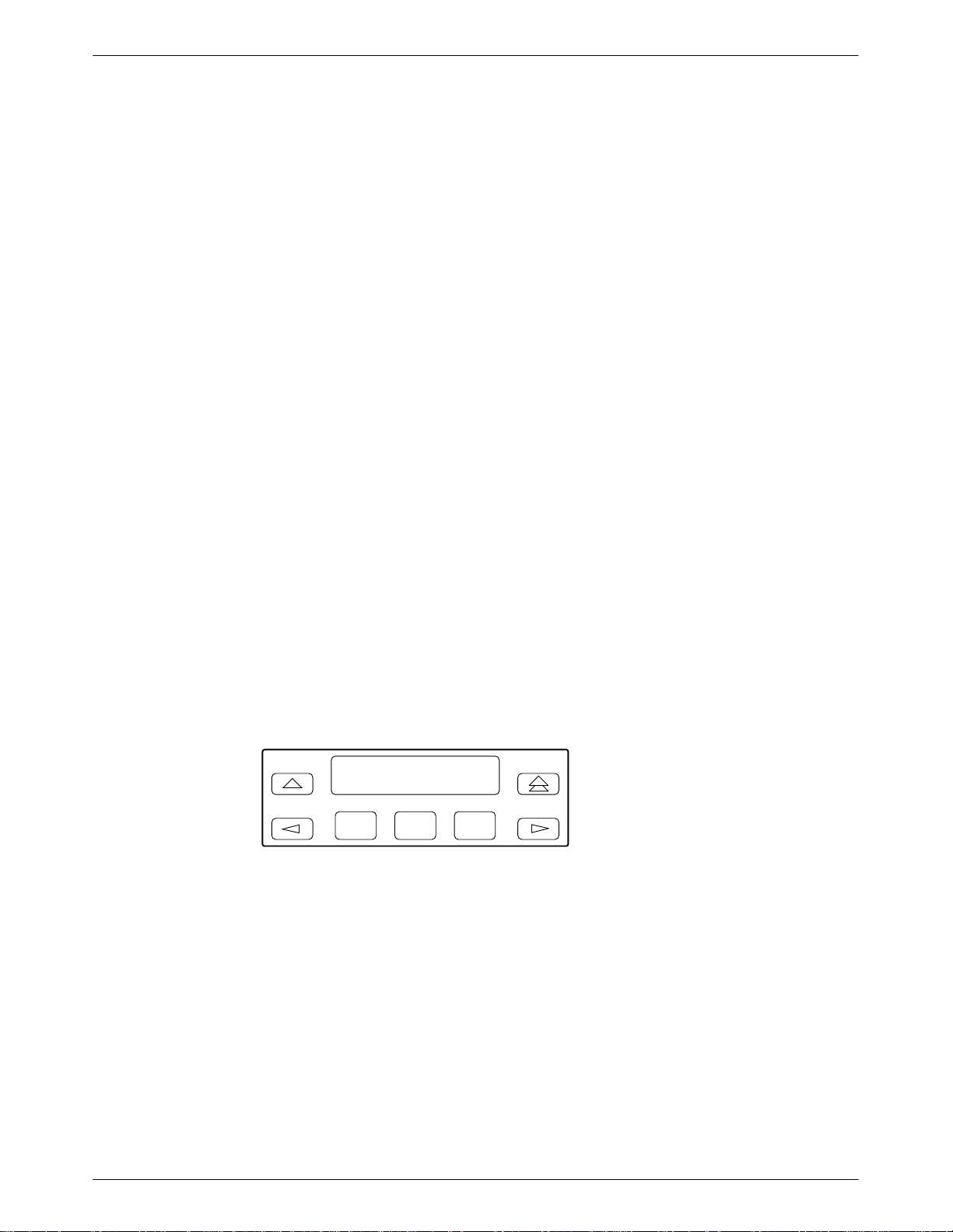
391x Series LCD and Keypad
Dial Backup
1 1-4. . . . . . . . . . . . . . . . . . . . . . . . . . . . . . . . . . . . . . . . . . . . . . . . . . . . . . .
1 Modem
, Model 391
1 Faceplate, and Optional SDU 3-4. . . . . . . . . . . . . . . . . .
2-10. . . . . . . . . . . . . . . . . . . . . . . . . . . . . . . . . . . . . . .
3-3. . . . . . . . . . . . . . . . . . . . . . . . . . . . . . . . . . . . . . . . . . . . . . . . . . .
3-6. . . . . . . . . . . . . . . . . . . . . . . . . . . . . . . . . . . . . . . . .
3-58. . . . . . . . . . . . . . . . . . . . . . . . . . . . . . . . . . . . . . . . . . . . . . . . . . . . . . .
iv November 1996 3910-A2-GN32-30
Page 9

Table of Contents
List of Tables
Table Page
1-1
Model 3910 and Model 391
3-1
3-1 SDCP LEDs 3-6. . . . . . . . . . . . . . . . . . . . . . . . . . . . . . . . . . . . . . . . . . . . . . . . . . . . . . . .
3-3 Top-Level Menu Status 3-9. . . . . . . . . . . . . . . . . . . . . . . . . . . . . . . . . . . . . . . . . . . . . . .
Common Operational Messages
3-4
Dial Access Security Messages
3-5
Health and Status Messages
3-6
Backup Status Screens
3-7
3-8 Valid Ranges for VF Thresholds 3-45. . . . . . . . . . . . . . . . . . . . . . . . . . . . . . . . . . . . . . . .
3-9 Valid Dial Command Modifiers 3-61. . . . . . . . . . . . . . . . . . . . . . . . . . . . . . . . . . . . . . . . .
4-1 DTE Interface Configuration Options 4-10. . . . . . . . . . . . . . . . . . . . . . . . . . . . . . . . . . . .
4-2 DTE Dialer Configuration Options 4-20. . . . . . . . . . . . . . . . . . . . . . . . . . . . . . . . . . . . . .
4-3 Line Dialer Configuration Options 4-25. . . . . . . . . . . . . . . . . . . . . . . . . . . . . . . . . . . . . .
4-4 Dial Line Configuration Options 4-30. . . . . . . . . . . . . . . . . . . . . . . . . . . . . . . . . . . . . . . .
4-5 Leased Line Configuration Options 4-33. . . . . . . . . . . . . . . . . . . . . . . . . . . . . . . . . . . . . .
4-6 V.42/MNP/Buffer Configuration Options 4-39. . . . . . . . . . . . . . . . . . . . . . . . . . . . . . . . .
4-7 Test Configuration Options 4-46. . . . . . . . . . . . . . . . . . . . . . . . . . . . . . . . . . . . . . . . . . . .
Miscellaneous Configuration Options
4-8
Result Codes
5-1
5-2 391x Series A
391x Series S-Registers
5-3
6-1 Edit Password Table Group Options 6-8. . . . . . . . . . . . . . . . . . . . . . . . . . . . . . . . . . . . .
6-2 Set Answer Security Group Options 6-10. . . . . . . . . . . . . . . . . . . . . . . . . . . . . . . . . . . . .
6-3 Set Originate Security Group Options 6-11. . . . . . . . . . . . . . . . . . . . . . . . . . . . . . . . . . . .
6-4 Security Configuration Options 6-14. . . . . . . . . . . . . . . . . . . . . . . . . . . . . . . . . . . . . . . . .
6-5 Security Database T
6-6 Security Database Table Using DTE-Side Passwords 6-18. . . . . . . . . . . . . . . . . . . . . . . .
6-7 Security Database Table Using Both VF-Side and DTE-Side Passwords 6-19. . . . . . . . .
Modem Health
B-1
B-2 Leased-Line Operation B-2. . . . . . . . . . . . . . . . . . . . . . . . . . . . . . . . . . . . . . . . . . . . . . . .
Dial Backup Operation
B-3
B-4 Modem — DTE Connection B-3. . . . . . . . . . . . . . . . . . . . . . . . . . . . . . . . . . . . . . . . . . .
Modem — VF Connection
B-5
B-6 Online Operation B-5. . . . . . . . . . . . . . . . . . . . . . . . . . . . . . . . . . . . . . . . . . . . . . . . . . . .
C-1 EIA-232-D Pin Assignments C-2. . . . . . . . . . . . . . . . . . . . . . . . . . . . . . . . . . . . . . . . . . .
VF Connector Pin Assignments
C-2
D-1 V
.25bis Commands
1 DCP LEDs 3-5. . . . . . . . . . . . . . . . . . . . . . . . . . . . . . . . .
T Commands
able Using VF-Side Passwords
. . . . . . . . . . . . . . . . . . . . . . . . .
3-12. . . . . . . . . . . . . . . . . . . . . . . . . . . . . . . . . . . . . . . .
3-13. . . . . . . . . . . . . . . . . . . . . . . . . . . . . . . . . . . . . . . . .
3-17. . . . . . . . . . . . . . . . . . . . . . . . . . . . . . . . . . . . . . . . . . . .
3-23. . . . . . . . . . . . . . . . . . . . . . . . . . . . . . . . . . . . . . . . . . . . . . . .
4-48. . . . . . . . . . . . . . . . . . . . . . . . . . . . . . . . . . . .
5-3. . . . . . . . . . . . . . . . . . . . . . . . . . . . . . . . . . . . . . . . . . . . . . . . . . . . . . .
5-5. . . . . . . . . . . . . . . . . . . . . . . . . . . . . . . . . . . . . . . . . . . .
5-15. . . . . . . . . . . . . . . . . . . . . . . . . . . . . . . . . . . . . . . . . . . . . . .
6-18. . . . . . . . . . . . . . . . . . . . . . . . .
B-1. . . . . . . . . . . . . . . . . . . . . . . . . . . . . . . . . . . . . . . . . . . . . . . . . . . . . .
B-2. . . . . . . . . . . . . . . . . . . . . . . . . . . . . . . . . . . . . . . . . . . . . . .
B-4. . . . . . . . . . . . . . . . . . . . . . . . . . . . . . . . . . . . . . . . . . . . .
C-3. . . . . . . . . . . . . . . . . . . . . . . . . . . . . . . . . . . . . . . . .
D-7. . . . . . . . . . . . . . . . . . . . . . . . . . . . . . . . . . . . . . . . . . . . . . . . . .
v3910-A2-GN32-30 November 1996
Page 10

COMSPHERE 3900 Series Modems
Table Page
D-2 V
.25bis Response Messages
E-1 ASCII Characters E-1. . . . . . . . . . . . . . . . . . . . . . . . . . . . . . . . . . . . . . . . . . . . . . . . . . . .
F-1 Factory Default Configuration Options F-2. . . . . . . . . . . . . . . . . . . . . . . . . . . . . . . . . . .
D-8. . . . . . . . . . . . . . . . . . . . . . . . . . . . . . . . . . . . . . . . . . . .
vi November 1996 3910-A2-GN32-30
Page 11

Preface
Objectives and Reader Assumptions
This
manual describes how to install and operate the COMSPHEREr 391x Series standalone and
carrier
-mounted modems. This manual assumes that you have a basic understanding of modems
and their operation.
How to Use this Manual
Chapter 1 provides technical specifications, information about the 391x Series modems’ features,
and the government requirements for using these modems.
Chapter 2 provides instructions for installing the 391x Series modems.
Chapter 3 provides the information required to operate the Model 3910 using the diagnostic
control panel and the Model 3911 using the COMSPHERE 3000 Series Carrier’
control panel (SDCP).
Chapter 4 provides the information required to set configuration options in the 391x Series
modems using the modem’
s diagnostic control panel.
s shared diagnostic
Chapter 5 provides instructions for displaying and changing A
Chapter 6 provides instructions for using the Dial Access Security feature.
Appendix A provides a menu tree for the 391x Series modems.
Appendix B provides instructions for performing diagnostic tests when data communication
problems occur.
Appendix C provides EIA-232-D and VF TELCO pin assignments.
Appendix D provides V.25bis dialing information.
Appendix E provides an ASCII translation chart.
Appendix F provides a list of all default configuration options available for the factory preset
configurations.
Appendix G provides diagrams of sample configurations for the 391x Series modems.
Appendix H provides an equipment list for the 391x Series modems.
The Glossary provides a description of terms used throughout this manual.
T commands and S-Registers.
vii3910-A2-GN32-30 November 1996
Page 12

COMSPHERE 3900 Series Modems
Related Documents
3000-A2-GA31
3610-A2-GZ45
3910-A2-GK41 COMSPHERE 3900 Series Modems, Models 3910 and 3911,
Call your sales representative to order additional product documentation.
COMSPHERE 3000 Series Carrier
3600 Hubbing Device Featur
Instructions
Installation Instructions
e Number 3600-F3-300, Installation
, Installation Manual
viii November 1996 3910-A2-GN32-30
Page 13

Overview
Introduction
Overview 1-1. . . . . . . . . . . . . . . . . . . . . . . . . . . . . . . . . . . . . . . . . . . . . . . . . . . .
Features 1-1. . . . . . . . . . . . . . . . . . . . . . . . . . . . . . . . . . . . . . . . . . . . . . . . . . . . . .
Multipoint Applications 1-2. . . . . . . . . . . . . . . . . . . . . . . . . . . . . . . . . . . . . . . . .
Leased Backup Applications 1-2. . . . . . . . . . . . . . . . . . . . . . . . . . . . . . . . . . . . .
COMSPHERE 391x Series Models 1-2. . . . . . . . . . . . . . . . . . . . . . . . . . . . . . . .
Standalone Model 3910 4-Wire/2-Wire Modem 1-3. . . . . . . . . . . . . . . . . . . .
Carrier-Mounted Model 3911 4-Wire/2-Wire Modem 1-4. . . . . . . . . . . . . . .
Government Requirements and Equipment Return 1-5. . . . . . . . . . . . . . . . . . . .
United States 1-5. . . . . . . . . . . . . . . . . . . . . . . . . . . . . . . . . . . . . . . . . . . . . . .
Canada 1-7. . . . . . . . . . . . . . . . . . . . . . . . . . . . . . . . . . . . . . . . . . . . . . . . . . . .
Technical Specifications 1-8. . . . . . . . . . . . . . . . . . . . . . . . . . . . . . . . . . . . . . . . .
The COMSPHERE 391x Series modems, a new generation of full-feature, high-speed modems,
offer reliable asynchronous and synchronous operation over leased-line or dial networks. The 391x
Series modems’ unique software defineability allows for the addition of future enhancements,
whether it is installing new features or firmware upgrades.
1
Features
The modem’
AT commands, CCITT V
permits the 391x Series modem to be used in a variety of applications and environments while also
allowing control over modem configuration, dialing, and diagnostics. The 391x Series modems
offer preset factory configurations containing the most often used modem settings.
The 391x Series modems have a wide variety of features.
• Four-wire/two-wire point-to-point or four-wire multipoint operation.
• Four-wire/two-wire leased-line modulations: V.32 terbo (19200 and 16800 bps), V.32bis
• Dial-line modulations: V.32 terbo (19200 and 16800 bps), V.32bis (14400, 12000, 9600,
•
s compatibility with a number of dialing methods and protocols, such as asynchronous
.25bis dialing, and the user
(14400, 12000, 9600, 7200, and 4800 bps), V.32 (9600 and 4800 bps), Paradyne
Point-to-Point Diagnostic (1200, 2400 bps), Trellis Multipoint (19200, 14400, 9600, 7200,
4800, and 2400 bps), V.22bis (2400 bps), V.27bis (4800 and 2400 bps), V.33 (14400 and
12000 bps), and V.29 (9600, 7200, and 4800 bps).
7200, and 4800 bps), V.32 (9600 and 4800 bps), Paradyne Point-to-Point Diagnostic (1200,
2400 bps), V.22bis (2400 bps), V.22 (1200 bps), V.23 (1200 and 600 bps), V.21
(300 bps), Bell 212A (1200 bps), and Bell 103J (300 bps).
Channel adaptive T
forward error correction for Trellis multipoint and high-speed point-to-point applications.
rellis-Coded Modulation, Paradyne’
-friendly diagnostic control panel (DCP),
s advanced T
rellis-Coded transparent
1-13910-A2-GN32-30 November 1996
Page 14

COMSPHERE 3900 Series Modems
• Mixed inbound rates for multipoint applications.
• Convenient migration to new or optional features through software downloading.
•
• Network management system (NMS) support through the COMSPHERE 6800 or
•
Extended data circuits with diagnostics.
6700 Series NMS using Advanced Diagnostic protocol (ADp).
Complement of self-tests, local and remote loopbacks.
• CCITT V
• Virtual error free data integrity with CCITT V.42 and MNP Level 4 error control.
Dial access security
•
• Automatic and manual backup with standby capabilities for 4-wire/2-wire leased-line
applications. (The backup facility may be either a 2-wire dial line or a 2-wire leased line.)
.42bis and MNP Class 5 data compression.
.
Multipoint Applications
In multipoint applications, leased-line circuits are used for time sharing the same front-end
processor (FEP) port with multiple remote locations. The FEP (via the control modem) regulates
traffic on the line by continuously polling the tributary DTE(s) in a predefined sequence. Only one
tributary can communicate with the control modem at a given time. Modems configured for Trellis
Multipoint (TMp) cannot be used in a point-to-point, constant carrier application. (Refer to the
Leased Line
section in Chapter 4 for configuration options.)
Leased Backup Applications
In
leased backup applications, a 2-wire leased line is used as the backup facility instead of the
normal 2-wire dial line. Plug the leased line into the jack labeled DIAL on the rear panel of the
modem (see Figure 2-1 in Chapter 2), and enable the Dual_Leased_Ln configuration option. (Refer
Leased Line
to the
indication, and call progression functions, you control the backup function as if it were a normal
dial backup.
section in Chapter 4 for configuration options.) Except for dialing, ring
COMSPHERE 391x Series Models
The 391x Series family is available in two models: the Model 3910, a 4-wire/2-wire standalone
modem, and the Model 391
variety of modulation schemes and network enhancements while still providing reliable,
high-speed data transmission using the latest in modem technology
1-2 November 1996 3910-A2-GN32-30
1, a carrier-mounted version of the standalone unit. Both models offer a
.
Page 15
Standalone Model 3910 4-Wire/2-Wire Modem
3
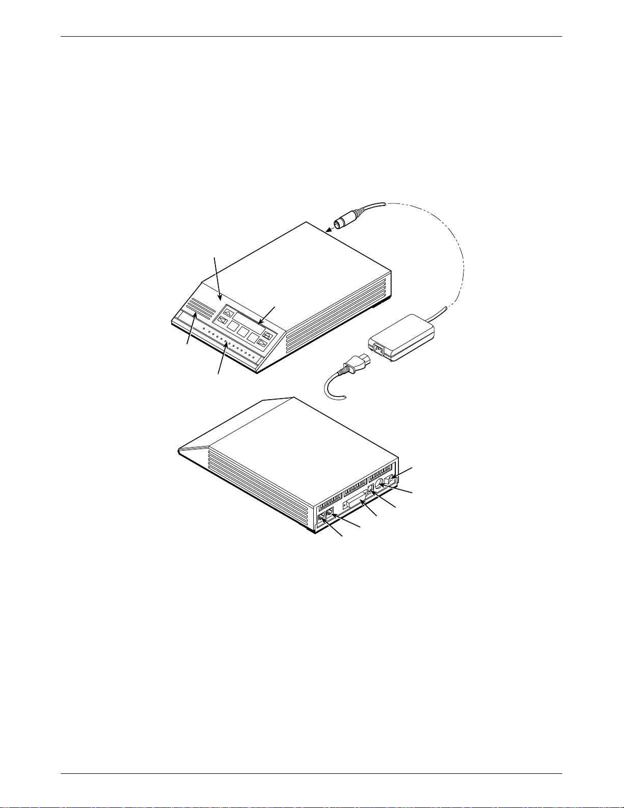
The standalone Model 3910 modem (Figure 1-1) is capable of either 4-wire/2-wire leased-line or
dial operation. The modem is controlled using either AT commands or the diagnostic control panel
(DCP). The DCP consists of a liquid crystal display (LCD), three function keys, four directional
keys, and a row of 13 LED status indicators. For a better understanding of DCP operation, refer to
Chapter 3,
DIAGNOSTIC
CONTROL
DCP Operation
PANEL
.
LCD AND
KEYPAD
Introduction
SPEAKER
STATUS
INDICAT ORS
POWER
CORD
DTE 1
DIAL
LEASED
POWER
SUPPLY
POWER
ON/OFF
POWER IN
NMS
496-14160-0
Figure 1-1. Model 3910
The rear of the modem contains an ON/OFF power switch, a low voltage dc power connector
8-pin modular connector (LEASED) for leased-line connection, an 8-pin modular connector
(DIAL) for dial-line or leased-line backup, a 4-pin modular connector (NMS) for network
management, and a DB-25-S DTE connector.
, an
Carrier-Mounted Model 3911 4-Wire/2-Wire Modem
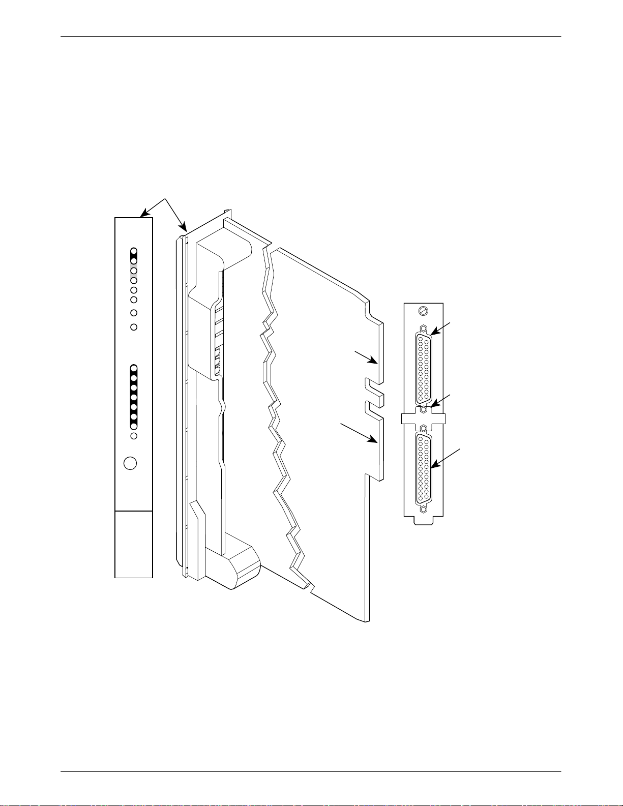
The carrier-mounted Model 3911 modem (Figure 1-2) is capable of either 4-wire/2-wire
leased-line or dial operation and installs into a COMSPHERE 3000 Series Carrier. The
1-33910-A2-GN32-30 November 1996
Page 16
COMSPHERE 3900 Series Modems
Status
142
125
103
104
105
106
107
108
109
Model 391
speaker jack for the carrier’
1’s faceplate has 16 LED status indicators for displaying modem activity and an audio
s optional speaker
.
The Model 3911 modem’s rear has two edge card connectors that mount into a connector plate
located on the rear of the carrier. This connector plate has two DB-25-S connectors, one providing
an EIA-232-D DTE interface and one for future functionality.
FACEPLATE
Pwr
Alrm
Test
Dial
RI
Busy
Serv
SQ
TXD
RXD
RTS
CTS
DSR
DTR
LSD
EIA232/V.24
EDGE CARD
CONNECTOR
FUTURE
USE
BACK
CONNECTOR
PLATE
EIA232/V.24
EIA232/V.24
CONNECTOR
GROUNDING
TAB
Front Panel
Spkr
3911
FUTURE
USE
496-14178b
(3800)
RS366A/V.25
(3600/3500)
V.35
Figure 1-2. Model 3911
The
Model 391
is a common bus to all devices installed in the carrier
1 derives ac power from the COMSPHERE 3000 Series Carrier’
. The user interface to any Model 391
s backplane, which
through the shared diagnostic control panel (SDCP), an optional feature which operates in a
1 is
1-4 November 1996 3910-A2-GN32-30
Page 17

manner similar to the DCP on the Model 3910. For a better understanding of DCP operation, refer
to Chapter 3,
The COMSPHERE 3000 Series Carrier has a total of 17 slots. The first slot, Slot 0, is reserved for
the shared diagnostic unit (SDU) while the remaining 16 slots can house up to 16 Model 391
modems, or a combination of Model 3911 modems and other units. For more details on the
COMSPHERE 3000 Series Carrier, refer to the
Manual.
DCP Operation
.
COMSPHERE 3000 Series Carrier
Government Requirements and Equipment Return
Certain governments require that instructions pertaining to modem connection to the public
switched telephone network be included in the installation and operation manual. Specific
instructions are listed in the following sections.
United States
Introduction
1
, Installation
NOTICE T
O USERS OF THE PUBLIC SWITCHED TELEPHONE NETWORK
1. This equipment complies with Part 68 of the FCC rules. On the equipment is a label that
contains, among other information, the FCC registration number and ringer equivalence
number (REN) for this equipment. The label is located on the bottom of the Model 3910
modem. This label is located on the Model 3911’s circuit card assembly
information must be provided to the telephone company.
Page A of this manual contains the Universal Service Order Codes (USOC) associated with
2.
the services on which the equipment is to be connected.
3. An FCC compliant telephone cord and modular plug is provided with this equipment. This
equipment is designed to be connected to the telephone network or premises wiring using a
compatible modular jack which is Part 68 compliant. See Installation Instructions for
details.
4. The ringer equivalence (REN) is used to determine the quantity of devices which may be
connected to the telephone line. Excessive RENs on the telephone line may result in the
devices not ringing in response to an incoming call. In most, but not all areas, the sum of
the RENs should not exceed five (5.0). To be certain of the number of devices that may be
connected to the line, as determined by the total RENs, contact the telephone company to
determine the maximum RENs for the calling area.
5. If the 391x Series modem causes harm to the telephone network, the telephone company
will notify you in advance that temporary discontinuance of service may be required. But if
advance notice is not practical, the telephone company will notify the customer as soon as
possible. Also, you will be advised of your right to file a complaint with the FCC if you
believe it is necessary
.
. If requested, this
6. The telephone company may make changes in its facilities, equipment, operations, or
procedures that could affect the operation of the equipment. If this happens, the telephone
company will provide advance notice in order for you to make the necessary modifications
in order to maintain uninterrupted service.
1-53910-A2-GN32-30 November 1996
Page 18

COMSPHERE 3900 Series Modems
7. If you experience trouble with this equipment, please contact your sales or service
8. The user is not authorized to repair or modify the equipment.
9. This equipment cannot be used on public coin service provided by the telephone company.
representative (as appropriate) for repair or warranty information. If the product needs to
be returned to the company service center for repair, contact them directly for return
instructions using one of the following methods:
• Via the Internet:
ia T
• V
elephone: Call our automated call system to receive current information via fax or
isit the Paradyne World W
ide W
eb site at http://www
.paradyne.com
V
to speak with a company representative.
— Within the U.S.A., call 1-800-870-2221
— International, call 813-530-2340
If the trouble is causing harm to the telephone network, the telephone company may
request that you remove the equipment from the network until the problem is resolved.
Connection to Party Line Service is subject to state tariffs. (Contact the state public utility
commission, public service commission or corporation commission for information.)
1-6 November 1996 3910-A2-GN32-30
Page 19

Canada
Introduction
NOTICE T
O THE USERS OF THE CANADIAN PUBLIC SWITCHED TELEPHONE NETWORK
The Canadian Department of Communications label identifies certified equipment. This
certification means that the equipment meets certain telecommunications network protective,
operational and safety requirements. The Department does not guarantee the equipment will
operate to the user’
s satisfaction.
Before installing this equipment, users should ensure that it is permissible to be connected to the
facilities of the local telecommunications company
acceptable method of connection. In some cases, the company’
. The equipment must also be installed using an
s inside wiring associated with a
single line individual service may be extended by means of a certified connector assembly
(telephone extension cord). The customer should be aware that compliance with the above
conditions may not prevent degradation of service in some situations.
Repairs to certified equipment should be made by an authorized Canadian maintenance facility
designated by the supplier
. Any repairs or alterations made by the user to this equipment, or
equipment malfunctions, may give the telecommunications company cause to request the user to
disconnect the equipment.
Users should ensure for their own protection that the electrical ground connections of the power
utility, telephone line and internal metallic water pipe system, if present, are connected together.
This precaution may be particularly important in rural areas.
CAUTION
Users should not attempt to make such connections
themselves, but should contact the appropriate electric
inspection authority, or electrician, as appropriate.
The Load Number is labeled on the equipment. The Load Number (LN) assigned to each terminal
device denotes the percentage of the total load to be connected to a telephone loop which is used
by the device to prevent overloading. The termination on a loop may consist of any combination of
devices subject only to the requirement that the total of the Load Numbers of all devices does not
exceed 100.
If your equipment is in need of repair, refer to the procedure in the
Government Requir
ements
and Equipment Return section earlier in this chapter.
1-73910-A2-GN32-30 November 1996
Page 20

COMSPHERE 3900 Series Modems
Technical Specifications
Table 1-1
Specifications
APPROVALS
FCC Part 15
FCC Part 68 Registration Number: (See label on modem)
shows the technical specifications for the 391x Series modems.
Table 1-1
(1 of 3)
Technical Specifications for 391x Series Modems
Description
Class A
UL
Model 3910 Listed to UL 1950
COMSPHERE 3000 Series Carrier Recognized to UL 1950
CSA
Model 3910 Certified to CSA C22.2 No. 950-M89
COMSPHERE 3000 Series Carrier Certified as a component to CSA C22.2 No. 950-M89
DOC
Model 3910 Certification Number: (See label on modem)
Model 3911 Certification Number: (See label on modem)
COMPATIBILITY Leased-Line Modulations:
Paradyne V.32 terbo (19200, 16800 bps)
CCITT V.32bis (14400, 12000, 9600, 7200, 4800 bps)
CCITT V.32 (9600, 4800 bps)
Paradyne Trellis Multipoint (19200, 14400, 9600, 7200, 4800,
2400 bps)
CCITT V.22bis (2400 bps)
CCITT V.27bis (4800, 2400 bps)
CCITT V.33 (14400, 12000 bps)
CCITT V.29 (9600, 7200, 4800 bps)
Paradyne Point-to-Point Diagnostic (1200, 2400 bps)
Dial-Line Modulations:
Paradyne V.32 terbo (19200, 16800 bps)
CCITT V.32bis (14400, 12000, 9600, 7200, 4800 bps)
CCITT V.32 (9600, 4800 bps)
CCITT V.22bis (2400 bps)
CCITT V.22 (1200 bps)
CCITT V.23 (1200, 600 bps)
CCITT V.21 (300 bps)
Bell 212A (1200 bps)
Bell 103J (300 bps)
Paradyne Point-to-Point Diagnostic (1200, 2400 bps)
1-8 November 1996 3910-A2-GN32-30
Page 21

Table 1-1
(2 of 3)
Technical Specifications for 391x Series Modems
Specifications Description
ENVIRONMENT
Operating Temperature
32°F (0°C) to 122°F (50°C)
Relative Humidity 5% to 90% (noncondensing)
Shock and Vibration Withstands normal shipping
Storage Temperature
–4°F (–20°C) to 158°F (70°C)
DTE INTERFACE
25-pin D-subminiature connector EIA-232-D/CCITT V.24
MODEL 3910 POWER SUPPL
Y
100 to 250 Vac, 50 to 60 Hz
AC POWER REQUIREMENTS
POWER CONSUMPTION
Model 3910 6 watts (typical, including power supply, speaker off)
Model 3911 4 watts (typical, each card) (Speaker consumption is
approximately 1 watt at high volume.)
DIMENSIONS
Weight 2.5 pounds (1.14 kg) Model 3910 (without power supply)
1.0 pounds (0.45 kg) Model 3911
Height 2.1 inches (5.4 cm) Model 3910
7.1 inches (18.1 cm) Model 3911
Width 7.6 inches (19.4 cm) Model 3910
0.9 inches (2.3 cm) Model 3911
Depth 12.1 inches (30.8 cm) Model 3910
13.4 inches (34.0 cm) Model 3911
TRANSMIT LEVEL
Leased Line (North America) 0 through –15 dBm (in 1 dBm decrements)
Factory default is 0 dBm
Leased Line (All Other Countries) 0 through –15 dBm (in 1 dBm decrements)
Factory default is country dependent
Dial Line (North America) –10 through –32 dBm (in 1 dBm decrements)
Factory default is Permissive (–9 dBm)
Dial Line (All Other Countries) Level setting is not accessible to the user
Factory default is country dependent
TELEPHONE INTERFACE
Leased-Line Connectivity JM8 (Model 3910)
50-pin mass termination (Model 3911)
Dial-Line Connectivity RJ11C Permissive
RJ21X Permissive 50-pin connector (Model 3911)
Introduction
1-93910-A2-GN32-30 November 1996
Page 22
COMSPHERE 3900 Series Modems
Table 1-1
(3 of 3)
Technical Specifications for 391x Series Modems
Specifications Description
DAT
A RA
TES
Leased Line 19200, 16800, 14400, 12000, 9600, 7200, 4800, 2400 1200 bps
Dial Line 19200, 16800, 14400, 12000, 9600, 7200, 4800, 2400, 1200,
600, 300 bps
ERROR CONTROL CCITT V.42
MNP 4-2
DAT
A COMPRESSION
CCITT V.42bis
MNP Class 5
1-10 November 1996 3910-A2-GN32-30
Page 23

Overview
Modem Installation
Overview 2-1. . . . . . . . . . . . . . . . . . . . . . . . . . . . . . . . . . . . . . . . . . . . . . . . . . . .
391x Series Modem Package 2-1. . . . . . . . . . . . . . . . . . . . . . . . . . . . . . . . . . . . .
Customer-Supplied Equipment 2-2. . . . . . . . . . . . . . . . . . . . . . . . . . . . . . . . .
Model 3910 Modem Installation 2-2. . . . . . . . . . . . . . . . . . . . . . . . . . . . . . . . . .
Connecting Cables to the Model 3910 Modems 2-3. . . . . . . . . . . . . . . . . . . .
DTE Connection 2-4. . . . . . . . . . . . . . . . . . . . . . . . . . . . . . . . . . . . . . . . . . . . . . .
Model 3910 4-Wire/2-Wire Leased-Line Connection 2-4. . . . . . . . . . . . . . . . . .
Dial Network Connection 2-4. . . . . . . . . . . . . . . . . . . . . . . . . . . . . . . . . . . . . . . .
Model 3910 Dial Backup Connection 2-4. . . . . . . . . . . . . . . . . . . . . . . . . . . . . .
Model 3910 Leased Backup Connection 2-4. . . . . . . . . . . . . . . . . . . . . . . . . . . .
Network Management System Connection 2-5. . . . . . . . . . . . . . . . . . . . . . . . . .
Power Supply Connection 2-5. . . . . . . . . . . . . . . . . . . . . . . . . . . . . . . . . . . . . . .
Modem Power-Up 2-5. . . . . . . . . . . . . . . . . . . . . . . . . . . . . . . . . . . . . . . . . . . . .
Selecting Factory Configuration Options 2-6. . . . . . . . . . . . . . . . . . . . . . . . . . . .
Using the Diagnostic Control Panel (DCP) 2-6. . . . . . . . . . . . . . . . . . . . . . . .
Using AT Commands 2-7. . . . . . . . . . . . . . . . . . . . . . . . . . . . . . . . . . . . . . . .
Removing and Replacing Model 3910 Modems 2-9. . . . . . . . . . . . . . . . . . . . . .
Model 3911 Modem Installation 2-9. . . . . . . . . . . . . . . . . . . . . . . . . . . . . . . . . . .
Removing and Replacing Model 3911 Modems 2-12. . . . . . . . . . . . . . . . . . . . . .
2
This
chapter provides a list of equipment supplied with the modem as well as a list of customer
supplied equipment. In addition, it describes how to install and remove the 391x Series modem,
and how to select a factory preset configuration using either the DCP or ATt
391x Series Modem Package
After opening the modem’s package, check for damage and verify that the following items are
present:
For the standalone model
• Installation instructions
Model 3910 modem
•
• Power supply
• One 6-position, 4-wire modular cord
• One 8-position, 8-wire modular cord
command set.
2-13910-A2-GN32-30 November 1996
Page 24

COMSPHERE 3900 Series Modems
For the carrier-mounted model
• Installation instructions
Model 391
•
• Rear connector plate with two DB-25-S edge card connectors
If any hardware components are damaged, notify your service representative. Return equipment
using the procedures described in the
Chapter 1.
Customer-Supplied Equipment
The following customer
using the Model 3910 modem:
• A DTE with an available EIA-232-D serial port.
• A standard EIA-232-D cable with a DB-25-P (plug) connector at one end to attach to the
modem.
• One of the following modular leased or dial network interfaces:
JM8 for leased-line applications.
—
— RJ1
The following customer-supplied equipment is required for the installation of a Model 3911
modem:
• A COMSPHERE 3000 Series Carrier.
1C for dial permissive applications.
1 modem
Government Requir
-supplied equipment is required to complete a data communications system
ements and Equipment Return section of
• A 50-pin mass termination cable.
• One of the following modular or 50-pin leased or dial network interfaces:
— RJ1
—
— 66 punchdown block.
• One Network Interface Module (NIM) for modems installed in Slots 1–8 and one NIM for
modems installed in Slots 9–16 (required for dial-line applications).
For installation of the COMSPHERE 3000 Series Carrier into a cabinet, refer to the COMSPHERE
3000 Series Carrier
1C for single line dial permissive applications.
RJ21X for multiple line dial permissive applications.
, Installation Manual.
Model 3910 Modem Installation
Before
installing your standalone modem, make sure your installation site is clean and
well-ventilated. Allow space around the modem for installing cables and telephone cords, and
make sure the modem is located within reach of the ac power outlet. The distance between your
modem and DTE should be minimized if DTE data rates exceed 19,200 bps. Also, low capacitance
cables may be necessary for speeds greater than 19,200 bps or distances greater than 50 feet.
2-2 November 1996 3910-A2-GN32-30
Page 25
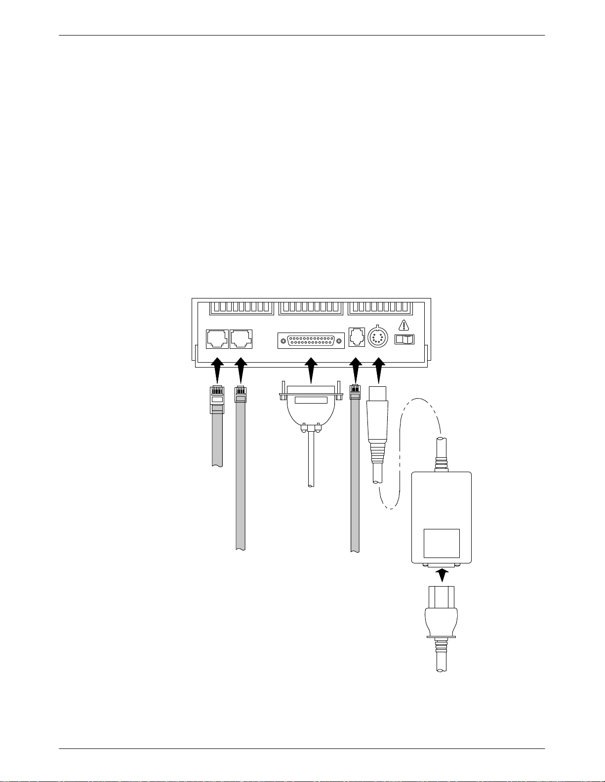
The rear panel of the Model 3910 modem (Figure 2-1) has the following switches and connectors:
• An ON/OFF power switch.
• An 8-pin DIN type power receptacle (PWR) for the dc power supply.
• An 8-pin modular keyed jack (LEASED) for 4-wire/2-wire leased lines.
• An 8-pin modular keyed jack (DIAL) for backup lines (2-wire dial or 2-wire leased).
• A 4-pin modular jack for the (NMS) network management system connection.
• A 25-pin DB-25-S receptacle for the DTE interface.
Connecting Cables to the Model 3910 Modems
Modem Installation
Figure 2-1
shows how Model 3910 modems are connected to certain TELCO jack types using the
appropriate cables. For pin assignments, refer to Appendix C.
DTE
8-POSITION,
8-CONDUCTOR
PLUG FOR
LEASED-LINE
NETWORK
OPERATION
6-POSITION,
4-CONDUCTOR
PLUG FOR
PERMISSIVE
DIAL NETWORK
OPERATION
NOTE:
THE DIAL JACK IS ALSO USED
FOR 2-WIRE LEASED BACKUP.
2
CONNECTOR
FOR DATA
TERMINAL
EQUIPMENT
OPERATION
DTE 3 DTE 4
DTE 1LEASED DIAL NMS PWR ON OFF
DB-25-P
SUB-MINIATURE,
4-CONDUCTOR
PLUG FOR
NETWORK
MANAGEMENT
OPERATION
POWER
SUPPLY
Figure 2-1. Model 3910 Rear Panel and Power Supply
2-33910-A2-GN32-30 November 1996
Page 26

COMSPHERE 3900 Series Modems
DTE Connection
Use the following procedures to connect the EIA-232-D cable from the modem to the DTE:
1.
Make sure the modem’
2. Connect the DB-25-P (plug) connector on the cable to the DB-25-S (socket) connector
labeled DTE (Figure 2-1) on the modem’
cable to the modem.
3. Connect the DB-25-P connector on the cable to the DB-25-S connector on the DTE. Use a
small screwdriver to secure the cable to the DTE.
s rear panel power switch is OFF
s rear panel. Use a small screwdriver to secure the
.
Model 3910 4-Wire/2-Wire Leased-Line Connection
Use the following procedures to connect a Model 3910 to the leased-line network interface:
1. Insert the 8-position, 8-conductor modular plug into the jack labeled LEASED
(Figure 2-1).
2. Insert the other end of the modular cord into the leased-line network interface.
Dial Network Connection
The telephone company provides the line termination jacks for the permissive service you request.
Advance coordination with the telephone company is suggested when connecting the modem to
telephone dial lines (PSTN).
In the Permissive mode, the modem’s transmit output level is fixed at –9 dBm. The telephone
company assumes that the line loss is 3 dB and no compensation is provided for additional losses.
A Permissive mode telephone line is usually terminated with a USOC RJ1
Model 3910 Dial Backup Connection
For the Model 3910, use the following procedures to connect the modem to the dial backup
network interface:
1. Insert the 6-position, 4-conductor modular plug into the jack labeled DIAL (Figure 2-1).
2. Insert the other end of the modular cord into the dial network interface.
Model 3910 Leased Backup Connection
For the Model 3910, use the following procedures to connect the modem to the 2-wire leased
backup network interface:
1. Insert the 8-position, 8 conductor modular plug into the jack labeled DIAL (Figure 2-1).
1C jack.
2. Insert the other end of the modular cord into the leased-line network interface.
2-4 November 1996 3910-A2-GN32-30
Page 27
Network Management System Connection
For the Model 3910, use the following procedures to connect the modem to the network
management system interface:
1. Insert the sub-miniature, 4-conductor modular plug of the 3600 Hubbing Device into the
jack labeled NMS (Figure 2-1). Refer to Document Number, 3610-A2-GZ45,
3600 Hubbing Device Featur
description of the 3600 Hubbing Device. Installation for the 3910 is the same as for the
3610 DSU.
2. Connect the 3600 Hubbing Device to the network management channel (Figure G-4 in
Appendix G).
e Number 3600-F3-300, Installation Instructions, for a
Power Supply Connection
Use the following procedures to connect the modem to an ac power outlet:
1.
Make sure the modem’
s power switch is in the OFF position.
Modem Installation
2. Insert the power supply’s 8-pin DIN connector into the modem’s rear panel dc power
receptacle (Figure 2-1).
3. Connect the power supply to a grounded ac power outlet.
Modem Power-Up
Once your modem is properly connected to the power supply
DTE, press the modem’s rear panel power switch to the ON position. The modem begins a
power-up self-test, in which all DCP LEDs light. This test takes several seconds to perform, and
verifies the operation of most hardware components within the modem. If successful, the LCD
displays
If a failure occurs during the self-test, the LCD displays Power On Selftst Failed for several
seconds. The LCD then displays the T
appearing on the top line of the LCD. Although a failure has occurred, the modem will attempt to
operate. This allows you to activate a more thorough self-test using the Test branch. Refer to the
est
section in Chapter 3.
T
, leased and/or dial lines, and the
Power on Selftst Passed and continues to the Top-Level menu screen.
Power On Selftst
Passed
F1
F2
F3
op-Level menu screen with the message
Power on Fail
2-53910-A2-GN32-30 November 1996
Page 28

COMSPHERE 3900 Series Modems
Selecting Factory Configuration Options
After
the modem passes the power
factory preset configurations.
The 391x Series modems have six factory preset templates that contain the most commonly used
configuration options (straps) for Synchronous Leased (Answer or Originate), Asynchronous
Leased (Answer or Originate), Trellis Multipoint (Control or Tributary), Asynchronous Dial,
Synchronous Dial, and UNIX Dial hardware network configurations. Your modem ships from the
factory with the Synchronous Leased (Answer) default configuration options stored in memory. If
Synchronous Leased (Originate), Asynchronous Leased (Answer or Originate), Trellis Multipoint
(TMp) (Control or Tributary), Async Dial, Sync Dial, or UNIX Dial is more appropriate for your
configuration, then you must change the factory setting using either the modem’
command set as described in the following sections.
The purpose of having preset configurations is so that you can have a “head start” in getting your
modem operating and reducing the amount of time required to configure your modem. For a better
understanding of DCP operation and factory preset configuration options, refer to Chapter 4, DCP
Configuration.
-up self-test, configure it for operation using one of the six
s DCP or the A
T
Using the Diagnostic Control Panel (DCP)
The DCP’s liquid crystal display (LCD) consists of two 16-character lines which display modem
status, control functions, and configuration options as well as indicating your location in the
Top-Level menu tree (Appendix A).
To change a factory template from the Sync Leased preset configuration using the DCP, perform
the following steps:
1. Press the function key below Configure to select the Configure branch.
The LCD now displays
Press the
2.
factory preset configurations.
Factory preset configurations are
Async Dial
must choose either
Control or Trib (Tributary) mode.
Press the
3.
press the corresponding function key to select your choice. (For certain factory templates
you will also need to choose the appropriate mode.)
Choose Function appears and displays the Edit and Save functions.
4.
5. Press the F3 key (Save) to save the new factory preset configuration to one of three
configuration areas, Active (Saved), Customer 1, or Customer 2.
key until Factory
, Sync Dial
Answer or Originate
key until the appropriate factory preset template appears on the LCD, and
Ld EditAr
, and
UNIX Dial
ea frm.
comes into view
Sync Leased, Async Leased, TMp
. If Sync Leased or Async Leased is selected, you
, then press the F1 key to display the
(Trellis Multipoint),
mode. If TMp is selected, you must choose either
(These three configuration areas are nonvolatile memory locations. Active (Saved)
contains the most recently saved changes to any configuration options. In the event of
power loss, the modem retrieves these configuration options. Customer 1 and Customer 2
are user-defined configuration areas.)
The LCD now displays
2-6 November 1996 3910-A2-GN32-30
Sav EditArea to.
Page 29

Modem Installation
6. Press the key until the appropriate configuration area appears on the LCD, then press
the corresponding function key to select your choice. (Saving configuration options to the
Active (Saved) configuration area automatically saves them to the Active (Operating)
configuration area.) The LCD displays Command Complete.
Refer to Chapter 4,
configuration options.
Using AT Commands
When
If the modem does not return OK, refer to Appendix B, Troubleshooting.
7. The modem is now configured with the selected factory template. Press the
key to
return to the Top-Level menu.
using A
DCP Configuration,
T commands, the following criteria must be met:
for more information regarding default factory
• Make sure the asynchronous DTE’s communication software is configured for 10-bit
character format (for example, 8 data bits, no parity, and 1 stop bit).
• Make sure the DTE cable is attached to the DTE connector on the rear of the 391x Series
modem and to the correct serial communications port on the asynchronous DTE.
• Configure the modem for
Using the DCP
. To verify that the modem is connected and functioning properly, enter the
Async Dial, Async Leased,
or
UNIX Dial
as described earlier in
following:
TYPE: AT
PRESS: Return (Enter)
The screen displays
OK.
NOTE
If the factory preset configuration is something other than Async
Dial, Async Leased, or UNIX Dial, you do not have AT command
control. To regain AT command control, select, via the DCP, the
Async Dial factory preset configuration as described earlier in
the DCP
.
Using
2-73910-A2-GN32-30 November 1996
Page 30

COMSPHERE 3900 Series Modems
To change a factory template using AT commands, perform the following steps. For more
information on changing factory templates using AT commands, refer to Chapter 5, A
Set and S-Registers
T Command
.
1.
Use the
AT&F&W command to load the appropriate factory configuration to the
appropriate storage area. Enter the following:
TYPE: AT&Fy&Wn
Where: y is one of the following Factory configurations:
0 for Async Dial
1 for Sync Dial
2 for Sync Leased (Answer)
3 for UNIX Dial
4 for Sync Leased (Originate)
5 for Async Leased (Answer)
6 for Async Leased (Originate)
7 for TMp (Control)
8 for TMp (Trib)
NOTE
Only &F0, &F3, &F5, and &F6 allow you to use AT commands after
saving a factory configuration. Any other selection removes AT
command control. The only way to return to AT command control is
through the DCP as described earlier in
Using the DCP
Where: n is one of the following storage areas:
.
0 for Active (Saved)
1 for Customer 1
2 for Customer 2
NOTE
These three configuration areas are nonvolatile memory locations.
Active (Saved) contains the most recently saved changes to any
configuration options. In the event of power loss, the modem
retrieves these configuration options. Customer 1 and Customer 2
are user-defined configuration areas.
PRESS: Return (Enter)
2. The selected factory configuration is saved.
To establish a connection with a remote modem, use the D (Dial) command. Refer to Chapter 5,
T Commands and S-Registers
A
, for more on AT commands.
2-8 November 1996 3910-A2-GN32-30
Page 31

Removing and Replacing Model 3910 Modems
To remove and replace a Model 3910 modem, perform the following steps:
1.
Make sure the modem is of
OFF position.
2. Disconnect the power cord from the ac power outlet, and then disconnect the dc power
cable from the connector on the rear of the modem.
3. Disconnect the leased-line and dial modular cords from the modem’s rear panel.
4. Disconnect the DTE interface cable from the modem’s rear panel.
If the modem is to be removed for service, return it to the company using the procedures
described in
Government Requir
fline, and press the modem’s rear panel power switch to the
ements and Equipment Return in Chapter 1.
Modem Installation
Install the replacement modem as described in the
5.
of this chapter, and configure it the same way as the modem being replaced.
Model 3911 Modem Installation
If the Model 3911 is removed from the carrier, always use a
ground strap when handling the modem. Always store the
Model 3911 in an antistatic bag when it is removed from the
carrier.
The
Model 391
both the operating power and the leased and/or dial network connections. For additional
information about the COMSPHERE 3000 Series Carrier, refer to the COMSPHERE 3000 Series
Carrier, Installation Manual.
The COMSPHERE 3000 Series Carrier has 17 slots which can hold up to 16 modems and one
shared diagnostic unit (SDU). The SDU is required when the modems in the carrier are controlled
by an NMS, or when multiple carriers in a cabinet configuration are to be controlled by a single
shared diagnostic control panel (SDCP). The SDCP of the COMSPHERE 3000 Series Carrier is
the user interface to the Model 3911 modem. A single SDCP can control up to eight carriers
containing up to 128 compatible modems.
1 is designed for installation in a COMSPHERE 3000 Series Carrier which supplies
Model 3910 Modem Installation section
CAUTION
The installation of a Model 3911 varies slightly if an SDCP is installed on the front of the carrier.
o install a Model 391
T
1. At the rear of the carrier
slot position as that intended for the modem.
Loosely fasten the plate. This allows for slight adjustments later when installing the
modem.
1 modem into the carrier without an SDCP, perform the following steps:
, install the rear connector plate. Make sure the plate uses the same
2-93910-A2-GN32-30 November 1996
Page 32

COMSPHERE 3900 Series Modems
Figure 2-2. Installing a Model 3911 Modem
2. At the front of the carrier, hold the modem vertically, with the latch on its faceplate in the
open position, and insert it into the top and bottom card guides of one of the slots
numbered 1–16 (Figure 2-2).
Slide the modem into the slot, aligning the modem with the rear connector plate, until the
backplane connector and DTE connector seat firmly into the back of the carrier. The
faceplate latch automatically closes as you push the modem into the carrier
modem into the carrier
, press the faceplate latch until a “click” is heard.
. To lock the
3. If the carrier is ON, the Power LED on the faceplate of the 3911 lights. After several
seconds the modem completes its power
-up self-test, in which all faceplate LEDs light.
Return to the rear of the carrier and tighten the rear connector plate.
If the modem is to communicate with an installed SDCP
, install the modem as described above and
perform the following steps:
1.
Press the
2. Press the F1 (
key on the SDCP
Select
"
) or F2 ( # ) key until the carrier number you want appears on the LCD.
. The cursor appears in the carrier selection entry.
The carrier number selection has a range of 1 to 8 since a single SDCP can control a
configuration of up to eight carriers. (This is only possible if the SDU is installed.)
Press the
3.
4. Press the F1 (
key to position the cursor on the slot selection entry.
"
) or F2 ( # ) key until the slot number you want (1–16) appears on the
LCD.
2-10 November 1996 3910-A2-GN32-30
Page 33

Modem Installation
5. Press the
key to place the SDCP in direct communication with the selected
Select
modem.
The LCD displays the Top-Level menu for the selected modem. In addition, the Front
Panel LED on the modem’
s faceplate and the
OK LED on the SDCP light.
6. Once you have determined that the modem is installed properly and completed its
power-up self-test, rotate the circuit pack lock until it covers the faceplate latch
(Figure 2-3) and tighten the retention screw on the circuit pack lock. This prevents the
modem from accidently being removed once it is installed in a carrier.
7. Configure the modem as described in the
Selecting Factory Configuration Options
earlier in this chapter.
section
Figure 2-3. Circuit Pack Lock
2-113910-A2-GN32-30 November 1996
Page 34

COMSPHERE 3900 Series Modems
Removing and Replacing Model 3911 Modems
CAUTION
If the Model 3911 is removed from the carrier, always use a
ground strap when handling the modem. Always store the
Model 3911 in an antistatic bag when it is removed from the
carrier.
It is not necessary to power down the carrier to remove and replace a Model 3911 modem. Perform
the following steps:
1.
Rotate the circuit pack lock until the release tab is exposed.
2. Press down on the release tab and pull the modem away from the carrier’
s backplane.
2-12 November 1996 3910-A2-GN32-30
Page 35

DCP Operation
Overview 3-2. . . . . . . . . . . . . . . . . . . . . . . . . . . . . . . . . . . . . . . . . . . . . . . . . . . .
Diagnostic Control Panels 3-2. . . . . . . . . . . . . . . . . . . . . . . . . . . . . . . . . . . . . . .
Model 3910 Diagnostic Control Panel 3-3. . . . . . . . . . . . . . . . . . . . . . . . . . .
Model 3911 Faceplate and Shared Diagnostic Control Panel (SDCP) 3-3. . .
Status Indicators 3-4. . . . . . . . . . . . . . . . . . . . . . . . . . . . . . . . . . . . . . . . . . . . . . .
Diagnostic Control Panel Operation 3-6. . . . . . . . . . . . . . . . . . . . . . . . . . . . . . . .
LCD Display 3-6. . . . . . . . . . . . . . . . . . . . . . . . . . . . . . . . . . . . . . . . . . . . . . .
Hidden Choice Indicators 3-7. . . . . . . . . . . . . . . . . . . . . . . . . . . . . . . . . . .
Other Indicators 3-7. . . . . . . . . . . . . . . . . . . . . . . . . . . . . . . . . . . . . . . . . .
Keypad 3-7. . . . . . . . . . . . . . . . . . . . . . . . . . . . . . . . . . . . . . . . . . . . . . . . . . . .
Menu Structure 3-8. . . . . . . . . . . . . . . . . . . . . . . . . . . . . . . . . . . . . . . . . . . . . . . .
Top-Level Menu Status and Operational Messages 3-9. . . . . . . . . . . . . . . . .
Quick Configuration Display 3-14. . . . . . . . . . . . . . . . . . . . . . . . . . . . . . . . . .
Status Branch 3-15. . . . . . . . . . . . . . . . . . . . . . . . . . . . . . . . . . . . . . . . . . . . . . . . .
Device Health and Status (DeviceHS) 3-16. . . . . . . . . . . . . . . . . . . . . . . . . . .
VF 3-19. . . . . . . . . . . . . . . . . . . . . . . . . . . . . . . . . . . . . . . . . . . . . . . . . . . . . . .
Identity 3-20. . . . . . . . . . . . . . . . . . . . . . . . . . . . . . . . . . . . . . . . . . . . . . . . . . . .
DTE 3-21. . . . . . . . . . . . . . . . . . . . . . . . . . . . . . . . . . . . . . . . . . . . . . . . . . . . . .
Backup 3-21. . . . . . . . . . . . . . . . . . . . . . . . . . . . . . . . . . . . . . . . . . . . . . . . . . . .
Options 3-23. . . . . . . . . . . . . . . . . . . . . . . . . . . . . . . . . . . . . . . . . . . . . . . . . . .
Record 3-24. . . . . . . . . . . . . . . . . . . . . . . . . . . . . . . . . . . . . . . . . . . . . . . . . . . .
Configure Branch 3-25. . . . . . . . . . . . . . . . . . . . . . . . . . . . . . . . . . . . . . . . . . . . . .
Poll List Branch 3-25. . . . . . . . . . . . . . . . . . . . . . . . . . . . . . . . . . . . . . . . . . . . . . .
Display 3-26. . . . . . . . . . . . . . . . . . . . . . . . . . . . . . . . . . . . . . . . . . . . . . . . . . . .
Clear 3-27. . . . . . . . . . . . . . . . . . . . . . . . . . . . . . . . . . . . . . . . . . . . . . . . . . . . .
Change 3-27. . . . . . . . . . . . . . . . . . . . . . . . . . . . . . . . . . . . . . . . . . . . . . . . . . . .
Add 3-28. . . . . . . . . . . . . . . . . . . . . . . . . . . . . . . . . . . . . . . . . . . . . . . . . . . . . .
Acquire 3-29. . . . . . . . . . . . . . . . . . . . . . . . . . . . . . . . . . . . . . . . . . . . . . . . . . .
Control Branch 3-30. . . . . . . . . . . . . . . . . . . . . . . . . . . . . . . . . . . . . . . . . . . . . . . .
Speaker 3-31. . . . . . . . . . . . . . . . . . . . . . . . . . . . . . . . . . . . . . . . . . . . . . . . . . .
Reset 3-31. . . . . . . . . . . . . . . . . . . . . . . . . . . . . . . . . . . . . . . . . . . . . . . . . . . . .
Data Stream 3-32. . . . . . . . . . . . . . . . . . . . . . . . . . . . . . . . . . . . . . . . . . . . . . . .
EIA LEDs 3-33. . . . . . . . . . . . . . . . . . . . . . . . . . . . . . . . . . . . . . . . . . . . . . . . .
Make Busy/Remove Make Busy 3-34. . . . . . . . . . . . . . . . . . . . . . . . . . . . . . . .
Service Line/Disconnect Service Line 3-35. . . . . . . . . . . . . . . . . . . . . . . . . . .
Download Software 3-35. . . . . . . . . . . . . . . . . . . . . . . . . . . . . . . . . . . . . . . . . .
Selecting Clone Remote 3-36. . . . . . . . . . . . . . . . . . . . . . . . . . . . . . . . . . . .
Clone Remote in Point-to-Point Configurations 3-36. . . . . . . . . . . . . . . . .
Clone Remote in Broadcast Configurations 3-37. . . . . . . . . . . . . . . . . . . . .
Clone Remote in Multipoint Configurations 3-38. . . . . . . . . . . . . . . . . . . .
Implementing a Clone Remote Operation 3-40. . . . . . . . . . . . . . . . . . . . . .
VF Thresholds Update 3-42. . . . . . . . . . . . . . . . . . . . . . . . . . . . . . . . . . . . . . . .
Test Branch 3-46. . . . . . . . . . . . . . . . . . . . . . . . . . . . . . . . . . . . . . . . . . . . . . . . . . .
Abort 3-46. . . . . . . . . . . . . . . . . . . . . . . . . . . . . . . . . . . . . . . . . . . . . . . . . . . . .
Self 3-47. . . . . . . . . . . . . . . . . . . . . . . . . . . . . . . . . . . . . . . . . . . . . . . . . . . . . . .
Loc Analog Loop 3-48. . . . . . . . . . . . . . . . . . . . . . . . . . . . . . . . . . . . . . . . . . . .
Rem Digital Loop 3-49. . . . . . . . . . . . . . . . . . . . . . . . . . . . . . . . . . . . . . . . . . .
Loc Digital Loop 3-50. . . . . . . . . . . . . . . . . . . . . . . . . . . . . . . . . . . . . . . . . . . .
Pattern 3-51. . . . . . . . . . . . . . . . . . . . . . . . . . . . . . . . . . . . . . . . . . . . . . . . . . . .
Sub-Network Health and Status Branch 3-53. . . . . . . . . . . . . . . . . . . . . . . . . . . . .
3
3-13910-A2-GN32-30 November 1996
Page 36

COMSPHERE 3900 Series Modems
Overview
Call Setup Branch 3-54. . . . . . . . . . . . . . . . . . . . . . . . . . . . . . . . . . . . . . . . . . . . . .
Dial 3-55. . . . . . . . . . . . . . . . . . . . . . . . . . . . . . . . . . . . . . . . . . . . . . . . . . . . . .
Disconnect 3-56. . . . . . . . . . . . . . . . . . . . . . . . . . . . . . . . . . . . . . . . . . . . . . . . .
Answer 3-57. . . . . . . . . . . . . . . . . . . . . . . . . . . . . . . . . . . . . . . . . . . . . . . . . . . .
Dial Standby/Return to Dial 3-57. . . . . . . . . . . . . . . . . . . . . . . . . . . . . . . . . . .
Change Directory 3-59. . . . . . . . . . . . . . . . . . . . . . . . . . . . . . . . . . . . . . . . . . .
Entering Telephone Numbers and Dial Command Modifiers into
Directory Locations 3-60. . . . . . . . . . . . . . . . . . . . . . . . . . . . . . . . . . . . .
Directory Status (Does Not Appear in North America) 3-61. . . . . . . . . . . .
Talk/Data Branch 3-62. . . . . . . . . . . . . . . . . . . . . . . . . . . . . . . . . . . . . . . . . . . . . .
Manual Dialing When the Remote Modem is Configured for
Auto-Answer 3-63. . . . . . . . . . . . . . . . . . . . . . . . . . . . . . . . . . . . . . . . . . . . .
Manual Dialing When the Remote Modem is Configured for
Manual Answer 3-64. . . . . . . . . . . . . . . . . . . . . . . . . . . . . . . . . . . . . . . . . . .
Security Branch 3-64. . . . . . . . . . . . . . . . . . . . . . . . . . . . . . . . . . . . . . . . . . . . . . .
Remote Branch 3-65. . . . . . . . . . . . . . . . . . . . . . . . . . . . . . . . . . . . . . . . . . . . . . . .
Diagnostic Control Panel Access 3-69. . . . . . . . . . . . . . . . . . . . . . . . . . . . .
This chapter describes how to use the diagnostic control panel (DCP) of the 391x Series modem. It
also describes how to select and use each branch of the T
Diagnostic Control Panels
There
are two types of diagnostic control panels (DCP), the DCP on the standalone Model 3910
modems and the shared diagnostic control panel (SDCP), an optional feature, used with the
Model 391
32-character liquid crystal display (LCD) and keypad through which Top-Level menu branches are
accessed to perform the following:
•
• Set up configuration options
•
• Initiate and disconnect dial operations
• Access remote modems through the local modem’
The LCD displays the result of any command initiated using the DCP
be performed from an attached asynchronous DTE using the AT command set.
1 installed into a COMSPHERE 3000 Series Carrier
Check modem status
Initiate diagnostic tests
op-Level menu tree.
. Both DCPs have a two-line,
s DCP
. Most of these operations can
3-2 November 1996 3910-A2-GN32-30
Page 37

Model 3910 Diagnostic Control Panel
1
The diagnostic control panel (DCP) of the Model 3910 modem (Figure 3-1) contains status
indicators, pushbutton-type keys, an LCD, and speaker grill.
DCP Operation
F3
SQRTS
104
COMSPHERE 3910
PWR ALRM
F1 F2
DTR
DIAG
108 142
CTS TXD LSD RXD TEST
109
103
106
105
Figure 3-1. Model 3910 DCP
Model 3911 Faceplate and Shared Diagnostic Control Panel (SDCP)
The shared diagnostic control panel (SDCP), Figure 3-2, is used to manage carrier-mounted
Model 391
The faceplate of the Model 3911 contains status indicators that monitor the operation of the
modem. After the SDCP is connected to the modem, the Front Panel indicator of the selected
modem lights to show that the modem is connected.
1 modems.
RATE
DIAL
496-14174-0
3-33910-A2-GN32-30 November 1996
Page 38

COMSPHERE 3900 Series Modems
1
Status Indicators
The 391x Series modems’ status indicators continuously provide information on the modem’s
operating condition. All of the status indicators on the Model 3910 appear on the DCP
(Figure 3-1), whereas the status indicators for the carrier-mounted Model 3911 are located on the
Model 3911’s faceplate, the SDCP
, and the SDU faceplate (Figure 3-2).
Diag
Diag
Status
OK
Alrm
In
Out
SDU
Status
Pwr
Alrm
142
Test
Dial
125
RI
Busy
Serv
SQ
103
TXD
104
RXD
105
RTS
106
CTS
107
DSR
108
DTR
109
LSD
Front Panel
Spkr
3911
CARRIER SLOTS 1–16
SDU12345678910111213141516
Select
OK Alarm BckUp Test EC
F1 F2 F3
COMSPHERE 3000
496-14175-0
SELECT
KEY
STATUS
INDICATORS
KEYPAD
LCD
OK Alarm BckUp Test EC
NETWORK
DEVICE
ALARM
DIAL
BACKUP
CORRECTION
TEST
MODE
ERROR
Figure 3-2. Optional SDCP, Model 3911 Faceplate, and Optional SDU
3-4 November 1996 3910-A2-GN32-30
Page 39

DCP Operation
The
standalone Model 3910 modem’
s DCP has 13 light-emitting diodes (LEDs), and the
carrier-mounted Model 3911 has 16 LEDs. These LEDs are listed and described in Table 3-1.
LEDs specific to one model type have the appropriate model number shown in the table.
Table 3-1
Model 3910 and Model 3911 DCP LEDs
Label
Color Indicates
Pwr green Power has been applied to the modem.
Alrm red Flashing. A major alarm has been detected in a remote 391x Series modem.
ON. A major alarm has been detected in the local modem. (For Health and
Status alarm conditions, refer to Table 3-6 in the
Device Health and Status
(DeviceHS) section of this chapter.)
Diag
(3910 only)
green The modem is receiving diagnostic communications (either a command or a
status poll).
Test/142 yellow Flashing. The modem is involved in a firmware upgrade. Normal operation is not
possible.
ON. The modem is involved in a test. Normal operation is not possible.
OFF. The modem is not involved in a test or firmware upgrade.
Dial yellow Flashing. The modem is attempting to establish a call over the dial network, or
the modem is in Dial Standby mode.
ON. The modem has established a dial connection.
OFF. A dial connection does not exist.
RI/125
green A ringing signal is being received.
(3911 only)
Busy
yellow The modem is placed in a forced busy condition and is off-hook.
(3911 only)
Serv
(3911 only)
yellow The modem is connected to the carrier service line rather than the normally
assigned network.
SQ yellow The receive telephone line signal is degraded or the modem’s data path has
been blocked (SQ flashes).
TXD/103 green The modem is receiving data from the DTE to transmit. (ON equals space.)
RXD/104 green Data is being transferred to the DTE. (ON equals space.)
RTS/105 green RTS signal is ON.
CTS/106 green CTS signal is ON.
DSR/107
green DSR signal is ON.
(3911 only)
DTR/108 green The DTE has turned ON DTR or the modem has forced DTR ON.
LSD/109 green The modem has detected a valid carrier signal and is capable of transferring
data to the DTE.
Rate
(3910 only)
yellow ON. The modem is connected at a data rate lower than the data rate it is
configured for.
OFF. The modem is connected at its configured data rate.
Front Panel
yellow The modem is connected to the carrier’
s SDCP
.
(3911 only)
3-53910-A2-GN32-30 November 1996
Page 40

COMSPHERE 3900 Series Modems
The SDCP LEDs are listed and described in Table 3-2.
Table 3-2
SDCP LEDs
Label Color Indicates
OK green Power is ON and the modem is capable of operating.
Alarm red The modem has detected a problem with its operation. For example, the modem
failed a self-test.
BckUp yellow The modem, originally configured for leased-line operation, is now operating on
dial networks in a Dial Backup mode.
Test yellow The modem is involved in a test. Normal operation is not possible.
EC green The modem is in Error Control mode.
Diagnostic Control Panel Operation
LCD Display
The 391x Series modem’s diagnostic control panel (DCP) is the user interface to all functions used
to configure and control the modem. In addition to the status LEDs, this interface includes the
liquid crystal display (LCD) and keypad (Figure 3-3).
HIDDEN CHOICE
INDICATOR
F2
F3
RETURNS
DISPLA
Y T
TOP-LEVEL
MENU
RIGHT
SCROLL
KEY
O
LEVE
CURRENT
DISPLAY
SCROLL
MOVES
UP ONE
L F
ROM
LEFT
KEY
LCD TO
LCD BOTTO
P L
INE
Leased:19.2
Status Configure
F1
FUNCTION KEYS
M L
INE
Figure 3-3. 391x Series LCD and Keypad
The LCD consists of a top line and bottom line, with each displaying a maximum of
16 characters at a time. If more information is available on the LCD than what is currently
displayed, an indicator appears in the top right or bottom right-hand corner of the LCD. Use the
or key to scroll in the indicated direction to display more selections onto the LCD.
3-6 November 1996 3910-A2-GN32-30
Page 41

Hidden Choice Indicators
The
hidden choice indicators serve as an alert that other choices are available besides what is
currently displaying on the LCD. These indicators appear as one of the following symbols:
DCP Operation
Other Indicators
Right Scroll Indicator
>
The right scroll indicator appears when more choices are available to the right of what is currently
displayed on the LCD.
Left/Right Scroll Indicator
The left/right scroll indicator appears when more choices are available to the left and right of what
is currently displayed on the LCD.
Left Scroll Indicator
<
The left scroll indicator appears when more choices are available to the left of what is currently
displayed on the LCD.
Other indicators may turn on depending on existing conditions, such as error detection,
informational alerts, and warnings. These indicators appear on the top or bottom line of the LCD.
Remote Mode Indicator
If the local 391x Series modem establishes a connection with the remote 391x Series modem via
the Remote branch, then
appears in the upper right corner of the LCD top line on both modems.
For more information on the Remote Mode indicator, refer to Remote Branch in this chapter.
Out of Range Indicator
Keypad
If an invalid threshold (out of range) is selected in the VF Threshold update process, then
appears in the lower right corner of the LCD bottom line. For more information on the Out of
Range indicator
, refer to VF Thr
eshold Update
in this chapter.
The DCP on the Model 3910 has seven keys while the optional SDCP of the COMSPHERE
3000 Series Carrier has eight keys. The additional key on the carrier is the
Select
key
, used to
connect the SDCP to a specific slot in the carrier.
Key
The
Pressing
No
appears. If Yes
key returns you to the Top-Level menu display from anywhere in the menu tree.
while changing configuration options displays the message
Save Straps? Y
is selected, changes made to configuration options are not saved and the T
is selected, then changes are saved to either Active (Saved), Customer 1, or
es No
op-Level menu
Customer 2 configuration areas.
Key
key moves you up one level in the menu tree.
The
and Keys
Use the
branches and selections into view
and
keys to move the viewing window left or right and to scroll the remaining
. A maximum of three selections can be displayed at one time.
. If
3-73910-A2-GN32-30 November 1996
Page 42

COMSPHERE 3900 Series Modems
These keys also allow you to move the cursor one character to the left or right on data entry
displays; for example, to allow entry of one digit at a time.
F1 F2 F3
Function keys select the LCD choice that appears above the function key; they are labeled F1, F2,
and F3. If a selection spans more than one function key
selection.
Select
The
used to connect the SDCP to a modem in a specific slot in the carrier.
Menu Structure
The menu tree is a hierarchical structure used to display functions that configure and control local
and remote 391x Series modems. It is accessed via the DCP and is shown in Appendix
Status PList
Configure
Keys
, then any of those keys choose that
Key (Model 3911 only)
key appears on the optional SDCP of the COMSPHERE 3000 Series Carrier. It is
Select
Displays
the current status of the modem along with
the data rate and the error control mode.
Security
Tlk/Data
Control
Test
“Status”
Call_Setup
SubHS
A.
Remote
The menu tree contains the following branches:
Status — Used to monitor the current status of the VF line and DTE interface as
well as view the identity of the modem.
Configure — Used to change and save the modem’s configuration options.
PList — (Poll List) Used to identify downstream modems in order to support
multipoint health and status polling and multipoint link download
broadcasting.
Control — Used to control the modem’s hardware and software functions.
Test — Used to begin and end various modem tests.
SubHS — (Sub-Network Health and Status) Used to display alarm conditions in
downstream modems.
Call Setup — Used to dial, disconnect, and answer telephone calls as well as store up to
24 telephone numbers in directory locations.
Talk/Data — Used to switch the modem between Talk mode (the modem is
disconnected from the VF line) and Data mode (the modem is connected
to the VF line) when dialing via either the DCP or a telephone.
Security — Used to control the modem’s dial access security.
Remote — Used to access and control a remote 3900 Series modem.
3-8 November 1996 3910-A2-GN32-30
Page 43

All
p
menu tree branches are discussed later in Chapter 3 except for Configure, which is discussed in
Chapter 4, and Security
, which is discussed in Chapter 6. Functions that appear on the LCD vary
depending upon the type of model installed, its operating mode, and software configuration.
Top-Level Menu Status and Operational Messages
Access to all menu tree branches from the DCP begins at the Top-Level menu, the head of the
menu hierarchy. The LCD’
bottom line displays the main menu tree branches as well as operational and security messages, as
listed in Table 3-4 and Table 3-5.
s top line identifies the modem status, as listed in T
Table 3-3
(1 of 4)
Top-Level Menu Status
DCP Operation
able 3-3, while the
Status
Normal
Operation
Message Indicates
Leased:
MR*
The modem is operating on leased lines and transmitting at the
displayed data rate.
Idle:
MR*
OnLine:
EC**
MR*
The modem is configured for dial network operation and is on-hook.
The modem is online, in Data mode, and operating at the displayed
data rate. EC (error control) appears if error control is operational.
Ring Indicate The local modem is receiving an incoming ring.
Test:
MR*
The modem is in test mode operating at the displayed data rate.
Alarm*** Make Busy The modem is in a Make Busy condition.
Power On Fail The modem has failed its Power-On Self-test.
SelfHealth Fail A failure has occurred in the modem’s hardware components.
Call Setup Off Hook The modem is off-hook and waiting to dial a telephone number.
Dialing The originating modem is dialing a telephone number.
Remote Ring The remote modem is ringing.
Training**** The modem is training or retraining.
EC Negotiating The local and remote modems are negotiating the highest possible
level of error control compatible between both modems. Once a
level is selected, this LCD message disappears.
* MR. Modem Rate indicates the data rate the modem is using. One of the following values appears:
300, 1200, 2400, 4800, 7200, 9600, 12.0 (12,000), 14.4 (14,400), 16.8 (16,800), or 19.2 (19,200) bps.
** EC. Error Control indicates the modem is online and using V.42 or MNP error control. One of the
following values appears after the modem rates listed above: MNP2, MNP3, MNP4, MNP5, V42, V42b,
or NoEC. (NoEC indicates the modem is connected in Buffer mode rather than error control. If an EC
value does not appear, then the modem is in Direct mode.)
*** The Alarm Status Messages only appear when the Normal Operation Status Messages appear; the
LCD alternates between the two message sets.
**** The Training message may also appear in normal Trellis Multipoint (TMp) operation.
3-93910-A2-GN32-30 November 1996
Page 44

COMSPHERE 3900 Series Modems
p
Table 3-3
(2 of 4)
Top-Level Menu Status
Status IndicatesMessage
Dial Backup or
Leased Backup
Standby: MR* The modem is operating in Dial Standby mode.
DialBckUp:
MR*
The modem is operating in Dial Backup mode at the displayed data
rate and is configured for Direct mode.
Call Failure
Backup:
EC**
Standby:
EC**
Busy Signal
Delayed
Number[
MR*
MR*
The modem is operating in Dial Backup mode and is configured for
error control and data compression on leased lines.
The modem is operating in Dial Standby mode and is configured for
error control and data compression on leased lines.
The answering modem is busy.
As a result of failed call attempts, this number cannot be called at
this time. Please try again later.
Dial Line in Use The modem is operating on dial networks when another call attempt
is issued.
Forbidden
Number[
As a result of failed call attempts, this number cannot be called
again.
Invalid Number The modem has dialed a telephone number not stored in a directory
location.
Line
The line is being used by the associated telephone.
Occupied[[
No Answer
Tone
The answering modem did not answer within the time limit specified
by the No Answer Timeout configuration option. The network tones
(if any) could not be interpreted by the modem.
* MR. Modem Rate indicates the data rate the modem is using. One of the following values appears:
300, 1200, 2400, 4800, 7200, 9600, 12.0 (12,000), 14.4 (14,400), 16.8 (16,800), or 19.2 (19,200) bps.
** EC. Error Control indicates the modem is online and using V.42 or MNP error control. One of the
following values appears after the modem rates listed above: MNP2, MNP3, MNP4, MNP5, V42, V42b,
or NoEC. (NoEC indicates the modem is connected in Buffer mode rather than error control. If an EC
value does not appear, then the modem is in Direct mode.)
*** The Alarm Status Messages only appear when the Normal Operation Status Messages appear; the
LCD alternates between the two message sets.
**** The Training message may also appear in normal Trellis Multipoint (TMp) operation.
[ The Delayed Number and Forbidden Number messages appear only in countries where the number of
repeat call attempts are restricted. The regulations vary in each country. If the number is delayed, the
value of the delay (in minutes) can be displayed by entering Directory Status (see Call Setup Branch).
[[ The Line Occupied message appears only in countries where the Offhook Detector is enabled. The
purpose of the Offhook Detector is to detect whether the telephone associated with the modem is
off-hook. It is enabled on a per-country basis, and this setting cannot be changed by a command. The
Offhook Detector is enabled in Austria, Germany, and Switzerland.
3-10 November 1996 3910-A2-GN32-30
Page 45

Table 3-3
(3 of 4)
Top-Level Menu Status
Status IndicatesMessage
Call Failure
No Dial–DTR The modem cannot dial because DTR is OFF.
Cont.
No Dial–Test The modem cannot dial because it is running a Test.
No Dial Tone The modem has aborted the call because it cannot detect a dial
tone.
No Quiet
Answer
Ringback
Timeout
The modem has detected No Quiet Answer (@) before the time-out
setting of the No Answer Disconnect configuration option.
The answering modem did not answer within the time limit specified
by the No Answer Timeout configuration option. A ringback signal
was detected.
Trunk Busy The modem is receiving a fast (trunk) busy.
Wrong Call The call was answered, but not by a modem. No answer tone.
Call Disconnect ATH Disconnect The modem has disconnected due to an ATH command.
Bad Lines Disc The modem has disconnected because the lines do not support the
modulation and/or data rate selected.
No Carrier Disc The modem disconnects due to the loss of carrier signal from the
remote modem.
DTR
The modem has disconnected due to the loss of DTR from the DTE.
Disconnect
EC Disconnect The modem has disconnected due to failure to negotiate Error
Control mode.
Inv Rate Disc When using V.32bis modulation, the remote modem does not
support the data rate used by the local modem.
LnCurrnt Disc The modem has disconnected due to the loss of line current.
LongSpace
The modem has disconnected due to the detection of a long space.
Disc
NoData Disc The modem has disconnected due to a lack of transmitted and
received data.
Disconnecting The modem has begun the disconnect sequence.
RmtCmnded
Disc
The modem has disconnected due to a V.32 Cleardown received
from the remote modem.
Talk Mode The modem is in Talk mode.
Firmware
Download
Result
DownldOnly
Mode
Frmware
Upgrade
RemClone
Failed
A local download of firmware or a remote cloning of firmware has
failed. The modem is currently in a Download Only mode in which
only another download attempt is possible.
A local download of firmware or a remote cloning of firmware was
successful.
A remote cloning of firmware has failed. This message appears on
the local modem’s LCD.
DCP Operation
3-113910-A2-GN32-30 November 1996
Page 46

COMSPHERE 3900 Series Modems
Status IndicatesMessage
Firmware
Download
Remote Clone
OK
Result
Cont.
Bcast Clone
Done
AT Command
Reset
Reset by AT
command
Messages listed in Table 3-4 are common operational messages that occur during modem
operation. These messages normally appear on the second line of the LCD.
Table 3-3
(4 of 4)
Top-Level Menu Status
A remote cloning of firmware was successful. This message
appears on the local modem’s LCD.
A broadcast cloning of firmware has completed. You must look
under the Control branch for cloning results. This message appears
on the local modem’s LCD.
The modem has performed a reset in response to an ATZ
command.
Table 3-4
Common Operational Messages
Common
Operational Message
Indicates
Please Wait... A command to a local device takes more than two seconds to complete.
Command Sent... A command is sent to a remote modem.
No Rem Response or
A remote modem does not respond to a command within 5 seconds.
Remote Modem Fail
Command Complete A command, issued to a local or remote modem, is completed.
Invalid Command The modem cannot complete a command.
3-12 November 1996 3910-A2-GN32-30
Page 47

DCP Operation
Messages listed in T
able 3-5 are dial access security messages.
Table 3-5
Dial Access Security Messages
Dial Access Security
Message
Indicates
Get VF PsWd The answering modem is waiting for the originating caller to transmit a VF
password.
Get DTE PsWd The answering modem is waiting to receive a valid DTE password from the
remote DTE.
VF PsWd Timeout The modem did not finish answering a call (disconnected) because the allowed
time limit was exceeded before the modem received a VF password from the
originating dialer.
Unknown DTEpswd The modem did not finish answering a call (disconnected) because the DTE
passwords received from the remote DTE were invalid.
No Orig PsWd The modem did not attempt to establish a call as requested because the AT dial
command did not contain an originate access password.
Unknown VF PsWd The modem did not finish answering a call (disconnected) because the modem
received an invalid VF password.
DTEpswd Timeout The modem did not finish answering a call (disconnected) because the allowed
time limit was exceeded before the modem received a DTE password from the
remote DTE.
Inval Orig PsWd The modem did not attempt to establish the call as requested because the
originate password in the AT dial command was not valid.
DTR Dial Blockd DTR dialing is not permitted when security is enabled. This message appears if
DTR dialing is used and Answer Access or Originate Access security is
enabled.
SecurityBlocked The access verification capabilities are not available and the modem does not
pass data to the DTE under any circumstances. This message appears only
when the modem is in base mode (a mode that occurs during a firmware
download) and Answer Access Security is enabled.
The Top-Level menu’s main branches appear on the LCD in the order of Status, Configure,
Control, T
est, Call Setup, T
chapter except for the Configure branch which is reserved for Chapter 4,
the Security branch which is reserved for Chapter 6,
alk/Data, Security
, and Remote. These branches are discussed in this
DCP Configuration, and
Dial Access Security
.
3-133910-A2-GN32-30 November 1996
Page 48

COMSPHERE 3900 Series Modems
Quick Configuration Display
The Quick Configuration display indicates the basic operational characteristics of the modem.
Leased:19.2
Status Configure
F1
F2
To access the Quick Configuration display from the Top-Level display
F3
, press the
key
.
Leased:19.2
abbb cdd ee ffff
F1
F2
F3
The modem’s Quick Configuration information appears on the LCD’s bottom line.
a Displays the network position of the modem. The letter C indicates this is a
control modem, and T indicates this is a tributary modem.
bbb Displays the network management address of the modem. The valid address
field range is from 001 to 256.
c Displays the DTE mode. The letter A indicates the modem is in Asynchronous
mode , and S indicates the modem is in Synchronous mode.
dd Displays the line mode. The letters LA indicate Leased Answer mode, LO
indicate Leased Originate mode, and D indicates Dial mode.
ee Displays the modem DTE port that is currently being displayed by the EIA
status indicators on the DCP.
P1 indicates Port 1.
CC
DC
indicates Control Channel.
indicates Diagnostic Channel.
ffff Display s th e mo d e m’s modulation scheme as shown below:
V
V32t indicates
V32b
V32
indicates V
indicates V
.32 terbo modulation.
.32bis modulation.
.32 modulation.
TMp indicates Trellis Multipoint modulation.
V22b
V27b
V33
V29
V22
V23
V21
212A
103J
indicates V
indicates V
indicates V
indicates V
indicates V
indicates V
indicates V
.22bis modulation.
.27bis modulation.
.33 modulation.
.29 modulation.
.22 modulation.
.23 modulation.
.21 modulation.
indicates Bell 212A modulation.
indicates Bell 103J modulation.
To exit the Quick Configuration function and return to the Top-Level menu, press the , , or
key
.
3-14 November 1996 3910-A2-GN32-30
Page 49

Status Branch
The Status branch of the Top-Level menu allows you to view the current status of the leased-line
or dial connection, the identity (for example, serial number and model number) of your equipment,
and the DTE interface.
Configure PList Control Test SubHS Call_Setup Tlk/Data Security Remote
Status
DCP Operation
“Status”
DeviceHS VF Identity DTE Options Record
1
Major
Minor
Status
Dial
Thresh
Security
Port1
SigQual
1,2
RcvLevel
1,2
Sig/Noise
1
NrEchLvl
1
FarEchLvl
FarEchDel
EchoFreqOff
NonLnearDist
Retrains
1
2
1
2
T
hes
e p
arameter
T
hes
e p
arameter
To
Ser#
Mod#
FRev
HPt#
FPt#
1
2
s a
ppea
s a
ppea
access Status from the T
LSD
DTR
DSR
Tst
TXD
RXD
RTS
CTS
r for V.32 t
r for T
relli
erbo
s M
, V
ultipoin
.32bis
Backup
Line = Pri 4W APL
Line = Pri 2W APL
Line = Bkup 2W APL
Line = Dial Backup
Line = Dial ONL
Line = No Sync
, and V.32 m
t m
odulation.
Y
odulations.
Display
Clear
op-Level menu, select Status.
Leased:19.2
Status Configure
F1
F2
F3
3-153910-A2-GN32-30 November 1996
Page 50

COMSPHERE 3900 Series Modems
Device Health and Status (DeviceHS)
DeviceHS provides a ‘‘snapshot” of current modem alarms which are active at the time the
DeviceHS function is selected.
T
o access DeviceHS from the Status branch, make the following selection:
Status: >
DeviceHS VF
F3
Select
DeviceHS.
F1
F2
Device HS: >
Major Minor
F1
If
alarms are present, press the appropriate function key to view the messages associated with these
F2
F3
alarms (Table 3-6). If needed, press the key to scroll to additional alarm types. If no alarms are
present, the word Normal
appears on the LCD.
3-16 November 1996 3910-A2-GN32-30
Page 51

Table 3-6
(1 of 2)
Health and Status Messages
DCP Operation
Type
Major
Message Indicates
Device Failure A device/self test has failed. The probable cause is a modem hardware
problem or diagnostic memory failure.
Facility Fault A severe data transport problem is occurring due to poor line
conditions. No signal or a very poor signal is being received.
Streaming DTE The modem is in an Antistreaming condition. The RTS input to the
modem was held ON for a period exceeding the time selected by the
RTS Antistream configuration option. (Refer to the
DTE Interface
section in Chapter 4 for a description of the RTS Antistream
configuration option.)
Access Security A dial access security alarm is active. (Refer to the Security section of
this table for dial access security conditions.)
Minor VF Threshold One or more of the analog parameter thresholds have been exceeded.
The probable cause is poor line conditions or improper threshold
settings. Thresholds may be set through the DCP or NMS commands.
DTE Alarm One or more of the DTE signals are in alarm mode. (Refer to the Port 1
section of this table for Port 1 DTE alarm conditions.)
Rate Fallback Due to poor line conditions, the modem’s transmit rate is below the
configured rate. (Refer to the
Leased Line
and
Dial Line
sections in
Chapter 4 for a description of configuration options affecting rate.)
Status Subtree Truncate Downstream health and status information has been truncated because
it overflowed system limits. There is a large amount of health and status
information in the subnetwork. This information can be recovered by
sending device health and status commands to specific modems.
Test Mode The modem or an upstream device is running a disruptive test.
Disabled The modem’s DTE port has been disabled.
On Dial Backup The modem is operating in Dial Backup mode.
FW Downloading A firmware download is in progress.
On Lease Backup The modem is operating in Lease Backup mode. This status occurs
only if the Dual Lease Line is enabled.
Primary Line Bad The modem is currently operating on the 2-wire backup facility, the
Lease Lookback option is enabled, and the modem does not detect
continuity on the primary 4-wire leased lines.
Backup Line
Good
The modem is currently operating on the primary 4-wire leased facility
with 2-wire leased lines selected as the backup facility, the Backup Line
Check option is enabled, and the modem detects continuity on the
2-wire backup leased lines.
Data Blocked The modem’s primary data path is blocked.
PSTN Test Fail The modem failed either the Dial Tone Detection or the Ring Tone
Detection portion of the Call Test command.
3-173910-A2-GN32-30 November 1996
Page 52

COMSPHERE 3900 Series Modems
y
Table 3-6
(2 of 2)
Health and Status Messages
Type IndicatesMessage
Dial Make Busy Mode The modem is in a Make Busy condition.
Service Line (Model 3911 only) The modem installed in a COMSPHERE 3000 Series
Carrier has been switched to a service line.
Short Hold Time The modem’s dial hold time has been shortened.
Non-Answering The modem is in a non-answering mode.
Thresh* RSL High
The received signal level (RSL) has exceeded the upper threshold.
Threshd
RSL Low
The RSL is less than the lower threshold.
Threshld
SNR Threshold The signal-to-noise ratio has exceeded the threshold.
Non-linear Dist The non-linear distortion has exceeded the threshold.
Retrains The number of retrains has exceeded the threshold.
Signal Quality The signal quality is less than the threshold.
Far Echo Threshd The far end echo level has exceeded the threshold.
Near Echo Thresh The near end echo level has exceeded the threshold.
Security
Database Reset The security database has been reset (passwords erased).
Password Protect Security password protection has been enabled.
Mode Change There has been a change in security mode. (Refer to Chapter 6,
Password
Change
Access Security
A security password has been changed.
.)
Database Change The security database containing passwords has been changed.
Port 1 Rx Data Alarm The DTE port’s RXD signal is in an alarm condition.
Tx Data Alarm The DTE port’s TXD signal is in an alarm condition.
DTR Alarm The DTE port’s DTR signal is in an alarm condition.
CTS Alarm The DTE port’s CTS signal is in an alarm condition.
RTS Alarm The DTE port’s RTS signal is in an alarm condition.
DSR Alarm The DTE port’s DSR signal is in an alarm condition.
LSD Alarm The DTE port’s LSD signal is in an alarm condition.
Auto Stream Dis The modem is in an Antistreaming condition. (Refer to the Streaming
DTE message in the Major Alarm section of this table.)
Disabled The modem’s DTE port has been disabled.
*Not supported in every modulation.
Dial
To
exit DeviceHS and remain in the Status Branch, press the key
Top-Level menu, press the
3-18 November 1996 3910-A2-GN32-30
key
.
. To exit and return to the
Page 53

VF
VF
displays the condition of the leased or dial connection.
To access VF from the Status branch, make the following selection:
Status: >
DeviceHS VF
DCP Operation
F1
F2
F3
Select VF.
Status:VF >
SigQual=Excelent
F1
F2
If the modem is receiving a signal, the signal quality appears on the LCD’
F3
s bottom line. Press the
key to scroll and view the receive signal level, signal-to-noise ratio, near end echo level, far
end echo level, far end echo delay, and echo frequency offset. If the modem is not receiving a
signal, the message
SigQual
No Signal
appears on the LCD.
Signal Quality displays the condition of the VF line. Possible values are
Excelent (Excellent), Good, Fair, Poor, or
for V.32 terbo, V
.32bis, and V
.32 modulations.
No Signal
. These values appear
RcvLevel Receive Signal Level displays, in decibels referenced to one milliwatt
(dBm), the actual strength of the incoming signal. This value appears for
V.32 terbo, V
.32bis, V
.32, and Trellis Multipoint modulations.
Sig/Noise
Signal-to-Noise Ratio displays, in decibels, the receive signal strength
relative to noise on the line. This value appears for V.32 terbo, V
.32bis, V
.32,
and Trellis Multipoint modulations.
NrEchLvl Near End Echo Level displays the signal level, in decibels referenced to one
milliwatt (dBm), of that portion of the transmit signal which has been
echoed back by the local line termination. This value appears for
V.32 terbo, V
.32bis, and V
.32 modulations.
FarEchLvl Far End Echo Level displays the signal level, in decibels referenced to one
milliwatt (dBm), of that portion of the transmit signal which has been
echoed back by the remote line termination. This value appears for
V.32 terbo, V
.32bis, and V
.32 modulations.
FarEchDel Far End Echo Delay displays the roundtrip delay in milliseconds of the far
end echo. This value appears for V.32 terbo, V
.32bis, and
V.32 modulations.
EchoFreqOff Echo Frequency Offset displays the frequency offset of the far end echo.
This value appears for V.32 terbo, V
.32bis, and V
.32 modulations.
3-193910-A2-GN32-30 November 1996
Page 54

COMSPHERE 3900 Series Modems
Identity
NonLnearDist
Non-Linear Distortion displays distortion which is usually associated with
pulse-code modulation (PCM) compandor noise on the phone line. This
value appears for Trellis Multipoint modulation.
Retrains Retrains displays the number of retrains over the last 15 minutes of
operation. The total 15-minute accumulation is updated every minute. This
value appears for Trellis Multipoint modulation.
T
o exit VF and remain in the Status Branch, press the
menu, press the
Identity displays the modem’
key
.
s serial number
, model number, firmware revision level, hardware
key
. To exit and return to the Top-Level
revision number and firmware part number. Retrieval of this information is useful if you are
purchasing additional or replacement modems and/or making firmware upgrades.
To access Identity from the Status branch, make the following selection:
Status:
VF Identity
F1
F2
F3
Press the
key until Identity appears. Select Identity.
Status:Identity >
Ser#=00000000
F1
F2
The modem’s serial number appears on the LCD’
F3
s bottom line. Press the
key to scroll and
view the model number, firmware revision level, hardware part number, and firmware part number.
Ser #
Serial number is an 8-digit number that identifies the modem.
Mod # Model number is an alphanumeric number that identifies the modem as
either a Model 3910 or Model 3911 modem.
FRev Firmware revision level is an alphanumeric number that identifies the level
of firmware loaded in the modem.
HPt # Hardware part number is an 11-digit number that identifies the circuit card in
the modem.
FPt # Firmware part number is an 11-digit number that identifies to customer
service personnel the firmware release number.
To exit the Identity function and remain in the Status branch, press the
to the Top-Level menu, press the
3-20 November 1996 3910-A2-GN32-30
key
.
key
. To exit and return
Page 55

DTE
DCP Operation
DTE displays the state and/or activity of the following interface leads: LSD, DTR, DSR, Tst, TXD,
RXD, R
TS, and CTS. The interface leads status is updated every 5 seconds.
To access DTE from the Status branch, make the following selections:
Status:
Identity DTE
F1
F2
F3
Press the key until DTE appears. Select DTE.
LSD DTR DSR Tst>
_ * _
F1
F2
The activity and state of the modem’s DTE signal appear on the LCD’
key to scroll other signals into view
F3
s bottom line. Press the
.
The LCD’s bottom line displays a pair of symbols for each interface lead. The first symbol
indicates the signal’
s activity since entering the DTE status display
. An * (asterisk) indicates at
least one transition while a blank space indicates no transitions.
The second symbol indicates the state of the interface lead at the sampling time. A
(solid block)
indicates a Space or ON condition while an underscore ( _ ) indicates a Mark or OFF condition.
key
To exit this function and remain in the Status branch, press the
key
Top-Level menu, press the
.
. To exit and return to the
Backup
The Status Backup function displays the configuration of the modem’s current operating line
facility and the configuration and condition of the inactive line.
NOTE
The modem’s rear panel has two line interface jacks: LEASE and
DIAL (see Figure 2-1 in Chapter 2). The jack labeled LEASE is the
APL primary interface and accepts either 2-wire or 4-wire APL. The
jack labeled DIAL is the backup interface and accepts either 2-wire
APL (Dual Lease Line) or Dial lines.
3-213910-A2-GN32-30 November 1996
Page 56

COMSPHERE 3900 Series Modems
To
access Backup from the Status branch, make the following selection:
Press the
key until Backup appears.
Status:
DTE Backup
F1
F2
F3
Select Backup.
Status:Backup >
Line=Pri 4w APL
F1
F2
F3
The configuration of the current operating line facility (either APL primary or backup) appears
(Refer to Table 3-7).
Press the
key to display the next screen.
Status:Backup <
Bkup:2wAPL=Good
F1
F2
F3
This screen displays the configuration and condition of the inactive line facility (either APL
primary or backup).
, and
There are four condition codes, Good, Bad, ????
‘ ’ (blank).
Table 3-7 provides information about the Status Backup screens. The first column lists all possible
configurations for the modem’
s currently active line. The second column lists all possible
configurations for the modem’s inactive lines. The third column provides information about the
inactive line condition.
XXXX represents the condition code of the inactive line.
3-22 November 1996 3910-A2-GN32-30
Page 57

Table 3-7
Backup Status Screens
DCP Operation
Active Line
1st Screen Display
Line=Pri 4w APL
or
Line=Pri 2w APL
Line=Bkup 2w APL
or
Line = Dial Backup
Inactive Line
2nd Screen Display
Bckup:2wAPL=XXXX
or
Bckup : Dial =(blank)
Pri 4w APL =XXXX
or
Pri 2w APL =XXXX
Line=Dial Only No second screen
display.
Line=No Sync No second screen
display.
Possible Inactive/Backup Line Condition
Good indicates that line continuity is detected.
Bad indicates that line continuity is not detected.
???? indicates that the line condition is unknown
(Backup Facility Check is making its first
determination of the line conditions since the last
retrain).
blank indicates that the Backup Line Check option is
disabled.
Good indicates the line condition is good.
Bad indicates the line condition is bad.
???? indicates the line condition is unknown (Lease
Lookback has not had enough time to make an initial
appraisal of the line conditions since the last retrain).
blank indicates the Lease Lookback option is
disabled.
NOTE: When the modem is configured for Dial Only,
there is no backup.
NOTE: The leased-line interface is disabled when the
factory default options are loaded from the
Async Dial, Sync Dial, or UNIX Dial
templates.
NOTE: No Sync appears when the modem is not
trained on either the primary or backup line
facility.
Options
To exit this function and remain in the Status branch, press the
Top-Level menu, press the
key
.
key
. To exit and return to the
The Options Status function displays all optional firmware features currently installed in the
modem. If no firmware options are installed, None_Installed
T
o access Options from the Status branch, make the following sections:
appears on the LCD.
Status:
DTE Options
F3
Press the
F1
F2
key until Options appears. Select Options.
3-233910-A2-GN32-30 November 1996
Page 58

COMSPHERE 3900 Series Modems
Options:Status >
V.29 V.33
Record
F1
F2
F3
If optional features are installed in the modem, they appear on the LCD’s bottom line. If other
features are installed, press the
To exit this function and remain in the Status branch, press the
Top-Level menu, press the
key to scroll other features into view.
key
.
key
. To exit and return to the
Record is a troubleshooting tool used by the end user in conjunction with support personnel. This
function allows the end user to retrieve and report any sequence faults to support personnel. A
sequence fault is an irregular or unexpected event.
There are two selections under Record: Display and Clear
. Display allows up to eight sequence
fault messages that have been recorded by the modem to be displayed on the LCD. If no sequence
faults have occurred, then Modem O.K.
appears.
Clear is used to remove all sequence fault messages from nonvolatile memory and the LCD.
T
o access Record from the Status branch, make the following selections:
Status: <
Options Record
Press the
F1
key until Record appears. Select Record.
F2
Record Status
Display Clear
F1
To
display sequence faults, select Display
F2
Record Number 1
Modem O.K.
F1
F2
F3
F3
.
F3
3-24 November 1996 3910-A2-GN32-30
Page 59

DCP Operation
The LCD displays the first sequence fault field. (Sequence fault fields range from 1 to 8 and are
identified by a number in the upper right corner.) Press the
The message
Modem O.K.
appears if no sequence faults have occurred.
key to view the remaining fields.
To remove sequence fault records from both the LCD and nonvolatile memory
message
To exit this function and remain in the Status branch, press the
Top-Level menu, press the
Configure Branch
The Configure branch of the LCD allows you to change and save the modem’s configuration
options. For configuration options and DCP configuration procedures, refer to Chapter 4, DCP
Configuration.
Poll List Branch
The Poll List function is not available on Point-to-Point control modems or Multipoint
Tributary modems..
The Poll List (Plist) branch of the Top-Level menu allows you to identify downstream modems in
order to support health and status polling and download broadcasting. The maximum number of
devices is 32 on the secondary channel and 64 on the diagnostic channel.
Modem O.K.
appears.
key
, select Clear
key
. To exit and return to the
. The
.
Status Configure
“Status”
Control
PList
Display Clear Change Add Acquire
Active
Delete
Skip
Test SubHS Call_Setup Tlk/Data Security Remote
(Tributary
o
nly)
3-253910-A2-GN32-30 November 1996
Page 60

COMSPHERE 3900 Series Modems
To access PList from the Top-Level menu, make the following selections:
Leased:19.2
PList Control
Display
F3
Press the
F1
F2
key until PList appears. Select PList.
Within a network link, a control modem can communicate with a tributary modem by using the
tributary modem’s network management address for polling functions. Each tributary modem must
have a different network management address. Refer to the Misc section in Chapter 4 for a
description of the network management address (NetMngmtAddress) configuration option.
Over a diagnostic channel a tributary modem can communicate with control modems by using the
control modem’s network management address for polling functions.
In the poll list, modems may be listed as either Active or Skip. Modems in the Active poll list are
polled by the upstream modem. Modems in the Skip poll list are passed over during the polling
process, but they are not deleted from the poll list.
Display allows you to view the modem’
s poll list.
To access Display from the PList branch, make the following selection:
Poll List: >
Display Clear
Select
F3
Display
F1
F2
.
NOTE
If there are no modems in the poll list when you select Display, the
message Poll List Empty! appears on the second line of the LCD.
Poll List:Disp
Nxt xxx yyyyyy
F1
F2
F3
3-26 November 1996 3910-A2-GN32-30
Page 61

If
there are modems in the poll list when you select Display
DCP Operation
,
Clear
xxx
Displays the network management address of the modem in the poll list.
yyyyyy Displays either Active or Skip to indicate the poll list in which the network
management
address is included.
Select Nxt to scroll through the entries in the Active or Skip poll lists.
To exit this function and remain in the PList Display branch, press the
key
to the Top-Level menu, press the
.
key
. To exit and return
The Clear function does not appear in Remote mode.
Clear deletes the modem’
s poll list.
To access Clear from the PList branch, make the following selection:
Poll List: >
Display Clear
F3
Select
Clear
F1
F2
.
Change
The message
Command Complete appears on the second line of the LCD to indicate that the poll
list has been cleared.
To exit this function and remain in the PList branch, press the
key
Top-Level menu, press the
.
key
. To exit and return to the
The Change function does not appear in Remote.
Change allows you to change the modem’
T
o access Change from the PList branch, make the following selections:
s poll list.
Poll List:
Clear Change
F3
Press the
F1
F2
key until Change appears. Select Change.
Change allows you to add modems to the Active poll list (Active), delete modems from both
Active and Skip poll lists (Delete), and move modems from the Active to the Skip poll list.
3-273910-A2-GN32-30 November 1996
Page 62

COMSPHERE 3900 Series Modems
Poll List:Chang >
Active Delete
F1
F2
F3
To implement Change, select the appropriate function (Active, Delete, or Skip). (For Skip, you will
need to press the
key until Skip appears.)
Poll List:yyyyyy
Ent x
F1
xx
F2
F3
The function field (yyyyyy) displays the function you selected (Active, Delete, or Skip).
The address field (xxx) displays the network management address of the modem to be changed.
The valid address field range is from 001 to 256.
To increment digits within the address field (xxx), use the
and
keys to position the cursor
( _ ) under the digit that will be incremented. Press the F2 () key to increment the digit.
Press Enter (Ent) to implement the function (yyyyyy) you selected (Active, Delete, or Skip). The
message
change has occurred. If the message
Command Complete appears on the second line of the LCD to indicate that the poll list
Poll List Check
appears, you have attempted to delete an
address that was not on the poll list, or you have attempted to add an address that was already on
the poll list. If the message
support secondary channel (V.29). If the message Poll Lst too Big
Poll List Err
or appears, you are in a point-to-point mode that does not
appears, you have entered a
number greater than the maximum number of downstream devices. To return to the selected
key
function (Active, Delete, or Skip), press the
. The address automatically increments upon
returning to this function.
To exit this function (Active, Delete, or Skip) and remain in the PList Change branch, press the
key. To exit and return to the Top-Level menu, press the
key
.
Add
The Add function does not appear in Remote mode or on control modems.
Add allows you to add the tributary modem to a control modem’s poll list. This function should be
initiated from only one tributary modem at a time.
o access Add from the Plist branch, make the following selections:
T
Poll List:
Change Add
F1
F2
Press the key until Add appears. Select Add.
3-28 November 1996 3910-A2-GN32-30
F3
Page 63

Poll List:Add
Command Complete
DCP Operation
Acquire
F3
s poll list.
key
.
key
. To exit and return to the
The
message
F1
Command Complete appears on the LCD to indicate that the tributary modem will
F2
be added to the control modem’
To exit this function and remain in the PList branch, press the
Top-Level menu, press the
The Acquir
e function does not appear in Remote mode.
Acquire allows you to acquire an active poll list consisting of all modems that are one tier
downstream. A modem will add to its poll list all downstream devices that respond to a poll.
To access Acquire from the Plist branch, make the following selections:
Poll List: <
Add Acquire
F1
F2
F3
Press the key until Acquire appears. Select Acquire.
NOTE
If an error message (OtherTestActive or Unable To Acquir)
appears on the second line of the LCD, move up one level in the
menu tree to clear the message and return to the PList Acquire
branch. The OtherTestActive message indicates that a test is
running which blocks the Acquire function. The Unable To Acquir
message indicates that the diagnostic network is in a busy state.
Poll List:Acquir
Abort xxx yyy
F1
F2
F3
The address field (xxx) increments sequentially from 001 to 256 as polls are transmitted from the
modem to the downstream modem(s). To be added to the modem’
s poll list, the device must
respond to a poll after receiving its address. The Acquire function can be canceled by selecting
Abort.
3-293910-A2-GN32-30 November 1996
Page 64

COMSPHERE 3900 Series Modems
The number field (yyy) indicates the total number of devices that responded to the modem’
These devices have been acquired for the poll list.
Select Abort or allow the function to complete.
The number field (yyy) indicates the total number of devices acquired for the poll list.
To exit this function and remain in the PList branch, press the
Top-Level menu, press the
Control Branch
The Control branch of the Top-Level menu allows you to manage hardware and software
functions, such as speaker volume, reset, busy out, and firmware download.
Poll List:Acquir
Num Acquired yyy
key
F3
.
F1
F2
key
. To exit and return to the
s polls.
Status Configure PList
Speaker Reset
To access Control from the Top-Level menu, make the following selections:
Data_Stream
“Status”
Test
Control
(3910
o
nly)
EIA_LEDs
Make_Busy
or
RemoveMakeBusy
Leased:19.2
Control Test
F1
F2
SubHS Call_Setup Tlk/Data Security Remote
(3911
o
nly)
Service_Line
or
DiscServiceLine
F3
Download_Code
(DownLoadSoftware)
VF_Thresh_Update
Press the
3-30 November 1996 3910-A2-GN32-30
key until Control appears. Select Control.
Page 65

Speaker
DCP Operation
Speaker allows you to make temporary adjustments to the modem’
s speaker volume. Upon a reset,
speaker volume returns to its configured setting. For more information on speaker settings, refer to
the
Misc
section in Chapter 4.
To access Speaker from the Control branch, make the following selection:
Control: >
Speaker Reset
F1
F2
F3
Select Speaker.
Speaker Control >
Off Low Med
F3
Press the
F1
F2
key and appropriate function keys to choose the desired selection.
DCP selections are
Reset
Off Turns the speaker off.
Low
Med
High
The message
To exit Speaker and remain in the Control branch, press the
Top-Level menu, press the
Adjusts the speaker to low volume.
Adjusts the speaker to medium volume.
Adjusts the speaker to high volume.
Command Complete
appears on the LCD.
key
.
key
. To exit and return to the
Reset causes the modem to stop operation and perform a complete program restart. The modem
begins the power
-up test sequence that ends with the T
op-Level menu displayed on the LCD.
Configuration options stored in an Active (Saved) configuration area are copied to the Active
(Operating) configuration area.
3-313910-A2-GN32-30 November 1996
Page 66

COMSPHERE 3900 Series Modems
T
o access Reset from the Control branch, make the following selection:
Control: >
Speaker Reset
Data Stream
F1
F2
F3
Select Reset.
The message
Reset appears momentarily before the modem performs the power
-up diagnostic test
sequence.
The Data Stream function is not available in Async mode.
Use Data Stream to enable or disable the modem’s data transmitter function.
To access Data Stream from the Control branch, make the following selections:
Control:
Data_Stream
F3
Press the
F1
F2
key until Data_Stream appears. Select Data_Stream.
The Data Stream action which is available (Disable or Enable) appears on the second line of the
LCD beside the word Port1. If the modem’s data transmitter is enabled, the word Disable
appears
to indicated that you may disable the data transmitter by selecting this action.
Data Stream
Port1 Disable
F1
F2
If you want to disable the modem’
Complete
appears, press the
F3
s data stream, press the F2 key
key to clear the message.
. When the message
Command
Data Stream
Port1 Enable
F1
F2
Press the F2 key again to enable the modem’
3-32 November 1996 3910-A2-GN32-30
F3
s data stream.
Page 67

DCP Operation
EIA LEDs
To exit this function and remain in the Control branch, press the
key
Top-Level menu, press the
.
key
. To exit and return to the
Use the EIA LEDs function to change the port that controls the front panel LEDs. This function
allows the front panel EIA LEDs to display the activity of a selected digital interface.
To access EIA LEDs from the Control branch, make the following selections:
Control:
EIA_LEDs
F3
Press the
F1
F2
key until EIA_LEDs appears. Select EIA_LEDs.
EIA_LED : xxxxx
Port1 CC
F1
F2
F3
Press the F1 key until the appropriate digital interface appears.
The xxxxx field displays the currently selected interface. The valid interfaces are Port1, and
depending on the configuration option, either CC (NMS Control Channel), or DC (Diagnostic
Channel). Refer to the section
Miscellaneous Configuration Options, Diag Connection
in Chapter 4.
Select the appropriate interface by pressing the corresponding function key.
EIA_LED : xxxxx
Command Complete
F1
After
selecting the desired interface, the message
F2
F3
Command Complete appears on the bottom line
of the LCD and the selected interface appears in the xxxxx field.
key
To exit this function and remain in the Control branch, press the
key
Top-Level menu, press the
.
. To exit and return to the
NOTE
The Port1 interface is the only display allowed on the 3911 modem,
therefore, the entire EIA LEDs branch is masked.
3-333910-A2-GN32-30 November 1996
Page 68

COMSPHERE 3900 Series Modems
Make Busy/Remove Make Busy
The Make Busy function forces the modem of
f-hook so it cannot answer a call. This is often used
with PBX systems to permit the busy out of a PBX port for rotary or hunt groups.
WARNING
To prevent violations of FCC and DOC regulations, this
function must only be used behind a user’
To
access Make Busy from the Control branch, make the following selections:
s PBX.
Control:
Make_Busy
F3
.
Press the
F1
F2
key until Make_Busy appears. Select Make Busy
Make Busy
Command Complete
F1
F2
F3
The modem is now in a forced busy condition. Command Complete
T
o remove the modem from Make Busy mode, press the
RemoveMakeBusy
appears.
key once and the
Control:
RemoveMakeBusy
F1
F2
Press any function key to select RemoveMakeBusy. The message
F3
Command Complete
on the LCD.
appears on the LCD.
key until
appears
3-34 November 1996 3910-A2-GN32-30
Page 69

Service Line/Disconnect Service Line
DCP Operation
The Service Line function allows you to switch a specific Model 391
1 installed in a COMSPHERE
3000 Series Carrier from normal leased or dial operation to service-line operation. This switch
only places the modem on the service line. For a connection to be established, you must still use
the normal dialing methods as described earlier in this chapter in the
A service line is an extra dial line connected to a COMSPHERE 3000 Series Carrier
Call Setup Branch
. This line is
section.
normally shared by up to eight Model 3911 modems installed in either Slots 1–8 or Slots 9–16.
However, by daisy chaining the service-line connector of one Network Interface Module (NIM) to
the service line of another NIM installed in the same carrier, you can permit all 16 modems to
share one service line. The service line can also be extended to other carriers in a cabinet. For more
information regarding daisy chaining of modems to the service line, refer to the COMSPHERE
3000 Series Carrier
A service line is ideal for a dial backup of Model 391
, Installation Manual.
1 modems operating on leased lines.
Remember that a service line can back up only one failed leased line at a time.
To enable Service Line from the Control branch, make the following selections:
Control:
Service_Line
F3
, when the modem places a call, instead of using the dial
Press the
F1
key until Service_Line appears. Select Service_Line to switch the modem from its
F2
normal dial line to the service line. Now
line, the call is placed on the service line.
Download Software
To disconnect the modem from the service line and resume normal operation, press the
once and the
Select DiscServiceLine. The call and service line disconnect and the message
Complete
key until DiscServiceLine appears.
Command
appears on the LCD.
key
The Download Software function sets parameters within the modem when transferring firmware to
one or more modems or when receiving firmware upgrades from a locally attached PC-based
controller. The latter is only performed by customer service personnel.
There are two selections under Download Software: Clone Remote and To Local via DTE. Clone
Remote is used to transfer an exact copy of the firmware currently stored in a 391x Series modem
to either one or more remote 391x Series modems or one or more DC-attached 391x Series
modems. Remote modems must be connected to the local modem via a leased-line network or an
established dial-line network. If these prerequisites do not exist, Clone Remote will not appear on
the LCD.
The second selection appearing on the LCD is T
o Local via DTE. This function permits firmware
upgrades to be transferred to a 391x Series modem. This type of download requires a locally
attached PC controller to be connected to the modem’
s DTE port as well as special download
software. Any downloads using this selection are intended to be performed by customer
service personnel only
.
3-353910-A2-GN32-30 November 1996
Page 70

COMSPHERE 3900 Series Modems
Selecting Clone Remote
To access DwnLoadSoftware from the Control branch, make the following selections:
NOTE
Clone Remote operations are not supported unless both local and
remote modems are 391x Series modems. (The 3800 or 392x
Series modems cannot be used in cloning operations with 391x
Series modems.)
Control:
Download_Code
Press the
F1
key until Download_Code appears. Press any function key to select
F2
Download_Code. The DwnLoadSoftware screen appears.
DwnLoadSoftware >
Clone_Remote
F1
F2
Press any function key to select Clone_Remote.
The next screen to appear is determined by the modem’s configuration. Refer to the appropriate
section (Point-to-Point, Broadcast, or Multipoint).
Clone Remote in Point-to-Point Configurations
Before using Clone Remote in point-to-point configurations, perform the following:
Make sure the 391x Series modems have an established leased-line connection using either
•
V.33, V.32 terbo, V
Chapter 4) or a dial network connection using either V.32 terbo, V.32bis or
V.32 modulation (refer to the Dial Line section in Chapter 4).
.32bis, V
F3
F3
.32, or V.29 modulation (refer to the
Leased Line
section in
• Make sure the remote modem’s Access From Remote configuration option is enabled (refer
to the Misc section in Chapter 4).
Make sure the password (Remote Access Password configuration option) is the same in both
•
the local and remote modems. (For an example of how to change the password, refer to the
Editing and Saving a Configuration Option section in Chapter 4.)
After completing these checks, proceed to the section titled
Implementing a Clone Remote
Operation, which follows the descriptions of multipoint cloning operations.
3-36 November 1996 3910-A2-GN32-30
Page 71

Clone Remote in Broadcast Configurations
A tributary modem configured for extended diagnostics (Diagnostic Connection configuration
option set to Modem(DC)) can perform two types of Remote Clone operations. It can clone the
upstream, VF connected, control modem (SC_Clone) or it can clone all the 391x modems attached
to its downstream Diagnostic Channel (DC_Broadcast).
Choose DLL Type >
SC_Clone
DCP Operation
From the Choose DLL T
an exact copy of the tributary modem’s firmware to the VF connected control modem.
Proceed to the section titled Implementing a Clone Remote Operation, which follows the
descriptions of multipoint cloning operations.
Cloning DC Broadcast Remote
Before using Clone Remote in DC Broadcast configurations, make sure the tributary modem’s
active poll list contains all the network management addresses for the control modems that receive
the download (refer to the Poll List section in this chapter), and ensure that the control modems are
responding properly to polls (refer to the
chapter).
From the Choose DLL T
to transfer an exact copy of the tributary modem’s firmware to the DC-connected control
modem(s) using the Active Poll list.
F1
F2
F3
ype screen, press the F1 key to select SC_Clone to request the transfer of
Choose DLL Type >
DC_Broadcast
F1
F2
F3
ype screen, press the
Sub-Network Health and Status Branch
key until DC_Broadcast appears. Press F1 or F2
sections in this
Proceed to the section titled Implementing a Clone Remote Operation, which follows the
descriptions of multipoint cloning operations.
3-373910-A2-GN32-30 November 1996
Page 72

COMSPHERE 3900 Series Modems
Viewing DC Broadcast Clone Results
Choose DLL Type >
DC_CloneResults
F1
From the Choose DLL T
ype screen, press the
results of the last DC_Broadcast clone operation. If the message
indicates that a multiple download was never initiated.
DC Clone Results
Nxt xxx Pass
F1
The address field (xxx) displays the network management address of one of the remote modems.
Pressing the F1 key allows you to select various remote modems to determine the download result
for those modems (Pass or Fail).
Clone Remote in Multipoint Configurations
A Trellis Multipoint (TMp) control modem can be used to download firmware to just one tributary
modem (Single) or to all of its tributary modems (Multiple).
F2
F2
F3
F3
key until DC_CloneResults appears to view the
Trib List Empty
appears, this
NOTE
A Trellis Multipoint (TMp) tributary modem cannot download
firmware to its control modem. To download firmware to a TMp
control modem use a point-to-point dial connection, an NMS, or a
PC controller.
Before using Clone Remote in multipoint configurations (Single or Multiple), perform the
following:
Make sure the 391x Series modems have an established leased-line connection using the
•
Trellis Multipoint (TMp) modulation (refer to the
Leased Line
section in Chapter 4).
• Make sure the remote modem’s Access From Remote configuration option is enabled (refer
to the Misc section in Chapter 4).
• For Single
download configurations, know the remote access password and the network
management address of the remote tributary modem that will receive the download. Refer to
the Misc
section in Chapter 4 for a description of the remote access password
(RemAccssPasswrd) configuration option and the network management address
(NetMngmtAddress) configuration option.
3-38 November 1996 3910-A2-GN32-30
Page 73

DCP Operation
• For Multiple download configurations, ensure that the control modem’
contains all the network management addresses for the remote tributary modems that will
receive the download (refer to the Poll List
tributaries are responding properly to polls (refer to the
Branch section in this chapter).
Cloning a Single TMp Remote
Press
the F1 key to select Single Clone Remote.
Choose DLL Type >
Single Multiple
F1
F2
F3
Choose Address:
Ent x
F1
xx
F2
F3
s active poll list
section in this chapter), and ensure that the
Sub-Network Health and Status
The address field (xxx) displays the network management address of the modem that will receive
the download. The valid address field range is from 001 to 256.
To increment digits within the address field (xxx), use the
and
keys to position the cursor
( _ ) under the digit that will be incremented. Press the F2 () key to increment the digit.
Press Enter (Ent) to select the modem that will receive the download.
Choose Password:
Ent y
F1
yyyyyyy
F2
F3
The password field (yyyyyyyy) displays the remote access password for the modem that will
receive the download.
To increment digits within the password field (yyyyyyyy), use the
and
keys to position the
cursor ( _ ) under the digit that will be incremented. Press the F2 ( ) key to increment the digit.
Press Enter (Ent) to select the modem that will receive the download.
After completing these actions, proceed to the section titled Implementing a Clone Remote
Operation.
3-393910-A2-GN32-30 November 1996
Page 74

COMSPHERE 3900 Series Modems
Cloning a Multiple TMp Remote
Choose DLL Type >
Single Multiple
Press
the F3 key to select Multiple Clone Remote.
After completing this action,
Viewing Multiple TMp Clone Results
From the Choose DLL T
view the results of the last multiple TMp clone operation. If the message Trib List Empty
this indicates that a multiple download was never initiated.
F1
F2
F3
proceed to the next section,
Choose DLL Type >
MPtCloneResults
F1
F2
F3
ype screen, press the
MPtCloneResults
Nxt xxx Pass
Implementing a Clone Remote Operation.
key until the MPtCloneResults screen appears to
appears,
F1
The address field (xxx) displays the network management address of one of the remote modems.
Pressing the F1 key allows you to select various remote modems to determine the download result
for those modems (Pass or Fail).
Implementing a Clone Remote Operation
The modem begins a transfer of its own program to the remote
modem. This process takes the communication link
out-of-service for several minutes depending on the data rate
of the link. If the Clone Remote process is started and then
interrupted, the remote modem is left in a partially programmed
state in which its functional capabilities are limited to those
required to initiate and complete another download attempt.
F2
F3
WARNING
3-40 November 1996 3910-A2-GN32-30
Page 75

Warning:Download
Abort_Download
DCP Operation
F1
F2
F3
At this point, if you do not want to continue this process, abort the transfer by selecting any
function key. This returns the modem to the DwnLoadSoftware menu. However, to continue with
the transfer
, press the
key to display the Reprogram_Remote selection.
Warning:Download
Reprogram_Remote
F1
F2
F3
Press any function key to begin the transfer.
RemClone Status
Establish Remote
F3
The local modem’
F1
F2
s LCD displays Establish Remote, indicating the modem is attempting to
establish a Remote Cloning Download session with the remote modem.
If unsuccessful, the modem remains in the Download Transfer mode. The LCD’
RemClone Failed
and the bottom line displays one of the following messages:
s top line displays
Incompat Modulat The modems are connected, but are using a modulation scheme other
than V
No Response
Access Disabled
Password Invalid
.33, V.32 terbo, V
The remote modem is not a 3900 Series modem or the connection
between the two modems is poor
The remote modem’
The local and remote modems’ passwords do not match. Correct the
.32bis, V
.32, V.29, or TMp.
.
s Access from Remote configuration is disabled.
problem and attempt another download from the local modem. If this
fails, contact your service representative.
No Cir
cuit There is no connection between the local and remote modem.
After successful establishment of a Remote Cloning Download session, the following screens
appear.
RemClone Status
Initializing
F1
F2
F3
3-413910-A2-GN32-30 November 1996
Page 76

COMSPHERE 3900 Series Modems
RemClone Status
Bank1:xxxx/yyyy
As data banks are transferred, the local and remote LCD’
download process, and the number of records sent versus the total number of records for that bank.
For Single
Remote Clone OK
place over the dial network, the modems disconnect when the download is complete.
If the Single
another download from the local modem. If this fails, contact your service representative.
VF Thresholds Update
The VF Thresholds Update function allows you to set the thresholds that determine the Health and
Status alarm conditions for the VF parameters. The following thresholds may be edited: RSL
High, RSL Low, Sig/Noise, NonLinear, Retrains/15min, Signal Quality, Near Echo, and Far
Echo. (For Health and Status alarm conditions, refer to Table 3-6 in the Device Health and
Status (DeviceHS) section of this chapter.)
To access VF Thresh Update from the Control branch, make the following selections:
F1
F2
F3
s bottom line displays the status of the
download applications, if the download is successful, the local modem displays
and the remote modem displays
download is unsuccessful,
RemClone Failed appears on the LCD’s top line. Attempt
Frmware Upgrade. If the download took
Control: <
VF_Thresh_Update
F3
Press the
F1
F2
key until VF_Thresh_Update appears. Press any function key to select
VF_Thresh_Update.
VF Thresholds
Edit Save Reset
F1
F2
F3
Select Edit.
In the following example, the RSL High threshold is changed from 09 (–dBm) to 10. This example
demonstrates VF threshold editing and saving. W
thresholds may be modified in this manner
values of
Excelent (Excellent), Good, Fair, Poor, or
ith the exception of Signal Quality, all VF
. Signal Quality uses a menu selection with possible
No Signal
. Editing and saving a VF threshold
is similar to editing and saving a configuration option. (For another example of editing and saving,
refer to the Editing and Saving a Configuration Option section in Chapter 4.)
3-42 November 1996 3910-A2-GN32-30
Page 77

RSL High (-dBm)
Nxt 0
9
DCP Operation
F1
F2
F3
In the example shown above, 09 is the upper (High) RSL threshold (in -dBm). T
10, make the following selections:
RSL High (-dBm)
r
F2
9
F3
Nxt 1
F1
Select the F2 ( ) key to increment the number above the cursor ( 0 ) to 1.
NOTE
Note that a warning ( ) appears on the second line of the screen if
you enter an invalid VF threshold (out of range). You will not be able
r
to save your edits until all thresholds are within their valid range.
Refer to Table 3-8 for valid VF threshold ranges.
o change the 09 to
RSL High (-dBm)
F2
r
F3
Nxt 19
F1
Press the key to move the cursor to the next position ( 9 ).
Select the F2 ( ) key to change the number above the cursor ( 9 ) to 0.
RSL High (-dBm)
Nxt 10
F1
F2
F3
NOTE
If you want to modify additional VF thresholds, select Nxt.
3-433910-A2-GN32-30 November 1996
Page 78

COMSPHERE 3900 Series Modems
To
save the edited threshold(s):
RSL High (-dBm)
Nxt 10
F1
F2
F3
Press the key to scroll up to the Edit/Save screen.
VF Thresholds
Edit Save Reset
F3
Select
Save.
F1
F2
If the edited VF thresholds are valid, the Save command stores them into nonvolatile memory.
When the Save completes, the message
Save Completed
appears.
Save VF Thresh
Thd Out of Range
F1
F2
If the edited VF threshold is invalid (out of range), the error message Thd Out of Range
F3
appears.
This indicates the Save procedure was unsuccessful. Return to the Edit screen and correct the
invalid threshold range.
To correct the invalid VF threshold, press the
key to return to the VF Threshold
Edit/Save/Reset screen.
VF Thresholds
Edit Save Reset
F1
F2
F3
Select Reset to restore the original default values into memory.
Repeat the Edit and Save procedure until the VF threshold(s) is valid and the Save completes
successfully (
To exit this function and remain in the Control branch, press the
Top-Level menu, press the
3-44 November 1996 3910-A2-GN32-30
Save Completed).
key
key
. To exit and return to the
.
Page 79

Table 3-8
Valid Ranges for VF Thresholds
DCP Operation
VF Thresholds
Valid Ranges Default Values
Receive Signal Level High 0 dBm to –15 dBm Above –9 dBm
Receive Signal Level Low –16 dBm to –50 dBm Below –23 dBm
Signal to Noise Ratio 5 dB to 40 dB Below 23 dB
Non-Linear Distortion 15 dB to 50 dB Below 30 dB
Retrains 1 to 256 trains 15 trains per 15 minutes
Signal Quality Excellent (lowest)
Good
Good
Fair
Poor
No Signal (highest)
Near Echo
0ā—38 dBm
Above –20 dBm
Far Echo 0—38 dBm Above –20 dBm
3-453910-A2-GN32-30 November 1996
Page 80

COMSPHERE 3900 Series Modems
Test Branch
The Test branch of the T
if you are having data communication problems, such as periodic character loss, random errors, or
constant format errors. By the process of elimination, you can usually isolate the fault in your
system.
There are six selections under Test: Abort, Self (Self-Test), Loc Analog Loop (Local Analog
Loopback), Rem Digital Loop (Remote Digital Loopback), Loc Digital Loop (Local Digital
Loopback), and Pattern. The only tests that can operate concurrently on a single modem are Pattern
with a Local Analog Loopback and Pattern with a Remote Digital Loopback. If any test is
operating, besides the two combinations just mentioned, it must be canceled before starting another
test.
The T
est branch only initiates and cancels tests. If any parameters need to be set, refer to the
section discussed in Chapter 4,
Status Configure PList Control
op-Level menu allows you to initiate various modem tests. Use these tests
Test
DCP Configuration
“Status”
SubHS
Test
.
Call_Setup Tlk/Data Security Remote
Abort
Abort Self Loc_Analog_Loop Rem_Digital_Loop Loc_Digital_Loop Pattern
T
o access the T
est branch from the Top-Level menu, make the following selections:
Leased:19.2
Control Test
F3
est.
Press the
F1
key until T
F2
est appears. Select T
Abort ends any test that is in progress and brings the modem back to the normal mode of
operation. Confirmation is provided by the Command Complete
message.
3-46 November 1996 3910-A2-GN32-30
Page 81

To access Abort from the Test branch, make the following selection:
Test: >
Abort Self
DCP Operation
Self
F1
F2
F3
Select Abort.
Test:Abort
Command Complete
F1
The
modem stops all tests currently in progress and displays the
F2
F3
Command Complete
status
message on the LCD.
To exit this function and remain in the T
Top-Level menu, press the
key
est branch, press the
.
key
. To exit and return to the
Self performs an internal self-test of the modem, which takes less than a minute to complete. The
modem must be offline; otherwise, Invalid Command
appears.
WARNING
When this test is run in Remote mode, it will cause the Remote
mode session to be lost. The Remote mode session can be
reestablished after the self-test is complete (usually one or two
minutes). If the remote self-test fails, there will be a Device
Failure alarm message when the remote modem’s Device
Health and Status (DeviceHS) branch is accessed.
To access Self from the Test branch, make the following selection:
Test: >
Abort Self
F1
F2
F3
Select Self. (All LCD cells and DCP status indicators light.)
3-473910-A2-GN32-30 November 1996
Page 82

COMSPHERE 3900 Series Modems
If
the modem passes the self-test,
modem fails, contact your service representative. If Invalid Command
modem is operating on dial lines or another test is in progress. If another test is in progress, select
Abort to clear the current test and try again. If the modem is operating on dial lines, disconnect to
clear the dial lines, and then choose Self. If the modem receives a ring signal during this test, the
test is canceled and the
NOTE
For tributary modems only, the test is delayed 30 seconds to allow
any outstanding network management messages to propagate
upstream before the VF channel is interrupted by the test.
Pass appears on the LCD. If it fails, Failed appears. If the
appears on the LCD, the
RI Abort
message appears.
Loc Analog Loop
To exit this function and remain in the T
Top-Level menu, press the
key
est branch, press the
.
key
. To exit and return to the
Loc Analog Loop performs a local analog loopback (CCITT V.54 Loop 3), Figure 3-4, that verifies
modem operation as well as the connection between the DTE and modem. The modem must be
offline and in Synchronous or Asynchronous Direct mode to perform this test, otherwise Invalid
Command appears.
Figure 3-4. Local Analog Loopback
To access Loc Analog Loop from the T
est branch, make the following selections:
Test:
Loc_Analog_Loop
F1
Press the
3-48 November 1996 3910-A2-GN32-30
key until Loc_Analog_Loop appears. Press any function key to start this test.
F2
F3
Page 83

Test:Local Loop
Started
DCP Operation
Rem Digital Loop
F1
F2
F3
NOTE
For tributary modems only, the test is delayed 30 seconds to allow
any outstanding network management messages to propagate
upstream before the VF channel is interrupted by the test.
The
message
Started appears on the LCD, and the Test LED lights for the duration of the test. If
Invalid Command appears on the LCD, another test is in progress. Select Abort to clear the
est T
current test and try again. If the Test Timeout configuration option is enabled, T
imeout
appears at the conclusion of the test. If it is disabled, the test operates until aborted. For more
information on the Test Timeout configuration option, refer to the Test
section in Chapter 4. A
Ring Indicate during this test can cause errors.
To exit this function and remain in the T
Top-Level menu, press the
key
est branch, press the
.
key
. To exit and return to the
This test is not available when using TMp modulation or Remote mode.
Rem Digital Loop performs a remote digital loopback (CCITT V.54 Loop 2), Figure 3-5. This test
can verify the integrity of the local modem, the communication link, and the remote modem. Any
data or pattern entered at the local DTE is sent to and returned from the remote modem. For this
test to operate properly, the modems must be operating at the same rate and in Synchronous or
Asynchronous Direct mode.
Figure 3-5. Remote Digital Loopback
3-493910-A2-GN32-30 November 1996
Page 84

COMSPHERE 3900 Series Modems
To access Rem Digital Loop from the T
est branch, make the following selections:
Test:
Rem_Digital_Loop
F3
Press the
F1
F2
key until Rem_Digital_Loop appears. Press any function key to start this test.
Test:Remote Loop
Started
F3
The
message
F1
F2
Started appears on the LCD, and the Test LED lights for the duration of the test. If
Invalid Command appears on the LCD, another test is in progress. Select Abort to clear the
est T
current test and try again. If the Test Timeout configuration option is enabled, T
imeout
appears at the conclusion of the test. If it is disabled, the test operates until aborted. For more
information on the Test Timeout configuration option, refer to the Test
To exit this function and remain in the T
Top-Level menu, press the
key
est branch, press the
.
section in Chapter 4.
key
. To exit and return to the
Loc Digital Loop
Loc Digital Loop is issued by a local modem and forces it to loopback any data received from the
remote modem (Figure 3-6). (This test operates the same as a CCITT V.54 Loop 2 except it is
issued at your modem.) This is useful if a remote modem is incapable of initiating a remote digital
loopback from its location. For this test to operate properly, the modems must be operating at
the same rate and in Synchronous or Asynchronous Direct mode.
Figure 3-6. Local Digital Loopback
3-50 November 1996 3910-A2-GN32-30
Page 85

DCP Operation
To access Loc Digital Loop from the T
est branch, make the following selections:
Test:
Loc_Digital_Loop
F3
Press the
F1
F2
key until Loc_Digital_Loop appears. Press any function key to start this test.
Test:Digitl Loop
Started
F3
appears
The
message
F1
F2
Started appears on the LCD and the Test LED lights. If Invalid Command
on the LCD, another test is in progress. Select Abort to clear the current test and try again. If the
est T
imeout
Test Timeout configuration option is enabled, T
appears at the conclusion of the
display. If it is disabled, the test operates until aborted. For more information on the Test Timeout
configuration option, refer to the Test
To exit this function and remain in the T
Top-Level menu, press the
section in Chapter 4.
est branch, press the
key
.
key
. To exit and return to the
Pattern
Pattern can transmit and receive a 511 bit error rate test pattern. It can also be used with a currently
running local analog loopback or a remote digital loopback to simulate data passing through the
modem. You will need to start the local analog or remote digital loopback test before you start the
pattern test. For this test to operate properly, the modems must be online and in Synchronous or
Asynchronous Direct mode (Figures 3-7 through 3-9).
Figure 3-7. Pattern Test and Local Analog Loopback Test
3-513910-A2-GN32-30 November 1996
Page 86

COMSPHERE 3900 Series Modems
Figure 3-8. Pattern Test and Digital Loopback Test
Figure 3-9. End-to-End Pattern Test
To access Pattern from the T
Test: <
Pattern
F1
Press the
key until Pattern appears. Select Pattern to start this test.
Test:Pattern >
BlksErrd=xxxxxxx
F1
est branch, make the following selections:
F2
F2
F3
F3
3-52 November 1996 3910-A2-GN32-30
Page 87

DCP Operation
BlksErrd=xxxxxxx displays the number of blocks of data found in error (block size is 1000 bits
per block). BlksRcvd=xxxxxxx
displays the total number of blocks of data received. The message
NoSync appears as a value for BlksErrd while the modem’s receiver is synchronizing. The
message
OvrFlw appears as the value for BlksErrd if the counter overflows.
Press the
key to display
BlksRcvd=xxxxxxx, number of blocks of data received.
The Pattern test can be exited and reentered without restarting the test. The BlksErrd and BlksRcvd
continue counting.
If the Test Timeout configuration option is enabled, T
test. If it is disabled, the test operates until aborted. For more information on the Test Timeout
configuration option, refer to the Test
To exit this function and remain in the T
Top-Level menu, press the
section in Chapter 4.
est branch, press the
key
.
Sub-Network Health and Status Branch
The Sub-Network Health and Status (SubHS) function is not available on multipoint
tributary modems or with certain modulations (V.29, V.33, V.22bis, and V.27bis).
The SubHS branch of the Top-Level menu allows you to display alarm conditions in downstream
modems.
“Status”
Status Configure Plist Control
Test
est T
imeout
appears at the conclusion of the
key
. To exit and return to the
Call_Setup Tlk/Data Security Remote
SubHS
To access the SubHS branch from the Top-Level menu, make the following selections:
Leased:19.2
Test SubHS
F3
Press the
F1
F2
key until SubHS appears. Select SubHS.
NOTE
If there are no modems in the multipoint poll list, the message Poll
List Empty! appears on the second line of the LCD.
3-533910-A2-GN32-30 November 1996
Page 88

COMSPHERE 3900 Series Modems
Sub-network HS
Nxt xxx yyyyyy
When
you select SubHS,
xxx Displays the network management address of the downstream modem selected.
yyyyyy Displays the status of the downstream modem. This message is updated every
Select Nxt to scroll through the entries in the poll lists.
To exit this function and return to the Top-Level menu, press the
Call Setup Branch
The Call Setup function is not available in TMp Control mode.
For dial backup applications, the Call Setup branch of the Top-Level menu allows you to dial,
disconnect, and answer telephone calls. For leased backup applications, the Call Setup branch
allows you to switch between the primary leased line and the backup leased line.
F1
F2
F3
several seconds to display the latest status. MAJOR, MINOR, an d STATUS
display Health and Status alarm conditions; refer to Table 3-6 in the Device
Health and Status (DeviceHS) section of this chapter for additional
information. UNKNWN appears when the
modem does not recognize the
downstream health and status information or device communication is not
established. Normal appears if no alarms are present. NO RSP appears when
the downstream modem does not respond to the poll.
key
.
In leased backup operation, a 2-wire leased line is used as the backup facility instead of the normal
2-wire dial line. Plug the leased line into the jack labeled DIAL on the rear panel of the modem
and enable the Dual_Leased_Ln configuration option. (Refer to the
Leased Line
section in
Chapter 4 for configuration options.) Except for dialing, ring indication, and call progression
functions, you control the backup function as if it were a normal dial backup.
3-54 November 1996 3910-A2-GN32-30
Page 89

“Status”
DCP Operation
Status Configure PList Control Test
(Dial
B
ackup
o
Dial
Disconnect
Answer
Return_to_Dial
Director
Dial_Standby
or
y L
ocation
To access the Call Setup branch from the Top-Level menu, make the following selections:
Leased:19.2
Call_Setup
F1
F2
nly)
s 1 - 2
F3
SubHS
Call_Setup
4
Change_Directory
Tlk/Data Security Remote
Directory_Status
(Does not appear
in North America)
Dial
Press the
key until Call_Setup appears. Select Call_Setup.
For dial backup applications, Dial allows you to dial any telephone number stored in directory
locations 1–24. Any telephone number dialed using the DCP must already exist in a directory
location. Refer to
Change Dir
ectory for information on storing telephone numbers in directory
locations.
For leased backup applications, Dial allows you to switch to the backup leased line. Any directory
location may be used. The remote modem cannot automatically answer the simulated call. Use the
Answer function of the remote modem in conjunction with the Dial function to manually switch to
the backup leased line.
To access Dial from the Call Setup branch, make the following selection:
Call Setup: >
Dial Disconnect
F1
F2
F3
Select Dial to display the first directory telephone number.
3-553910-A2-GN32-30 November 1996
Page 90

COMSPHERE 3900 Series Modems
DialDirectory:
Nxt 01:5551234
F1
F2
F3
To view other directory locations, select Nxt.
DialDirectory:
Nxt 02:5461879
F1
F2
F3
Once the directory location you want appears on the LCD, press the F2 or F3 key to dial the
number.
DialDirectory:01
Off Hook
F3
able 3-3) appears on the LCD. If the
able 3-3).
The
Call Setup status
F1
F2
Off Hook appears during the connection process. If the connection is
successful, one of the Normal Operation status messages (T
connection is not successful, the LCD displays one of the Call Failure status messages (T
Disconnect
For dial backup applications, use this function when you want to disconnect an established call on
a dial line. For leased backup applications, use this function to switch between the primary leased
line and the backup leased line.
T
o access Disconnect from the Call Setup branch, make the following selection:
Call Setup: >
Dial Disconnect
F3
Select
Disconnect.
F1
F2
Disconnect
Command Complete
F1
F2
F3
3-56 November 1996 3910-A2-GN32-30
Page 91

DCP Operation
For
dial backup applications, the modem goes on-hook (hangs up) and the call is disconnected.
The Command Complete
status message appears.
Answer
To exit this function and remain in the Call Setup branch, press the
key
the Top-Level menu, press the
.
key
. To exit and return to
For dial backup applications, Answer allows the modem to go off-hook, generate an answer tone,
and begin the handshaking process with the calling modem. Use the Answer function when the
Auto-Answer Ring Count configuration option is disabled. (Refer to the
Line Dialer
section in
Chapter 4.)
For leased backup applications, Answer allows the modem to begin the handshaking process with
the remote modem.
o access Answer from the Call Setup branch, make the following selections:
T
Call Setup:
Answer
F3
.
Press the
F1
F2
key until Answer appears. Select Answer
The modem goes off-hook and attempts to establish a connection in Answer mode. The Command
Complete
To exit this function and remain in the Call Setup branch, press the
the Top-Level menu, press the
Dial Standby/Return to Dial
When the modem is operating in Dial Backup mode (DialBckUp), Dial Standby and Return to Dial
allow the modem to switch back and forth between primary leased-line and primary leased-line
backup operation while still maintaining the backup connection (Figure 3-10). Switching between
backup and primary leased-line operation can be performed manually or automatically. (Refer to
Leased Line
the
Answer
Command Complete
F1
F2
F3
status message appears on the LCD.
key
. To exit and return to
key
.
section in Chapter 4 to enable the Automatic Dial Backup configuration option.)
3-573910-A2-GN32-30 November 1996
Page 92

COMSPHERE 3900 Series Modems
DIAL BACKUP LINE
DIAL
STANDBY
RETURN
TO DIAL
XX
LEASED-LINE
FAILURE
Figure 3-10. Dial Backup
Under normal backup conditions, when a problem occurs on the primary leased line, the modems
establish a connection over the backup network.
Call Setup:
Dial Standby
F1
F2
F3
When this occurs, Dial Standby appears on the LCD in the Call Setup menu branch. If you select
Dial Standby
, the modem switches back to the primary leased line while still maintaining the
backup connection. As a result, Return_to_Dial appears on the LCD instead of Dial Standby
MODEMMODEM
496-13081-01
.
Call Setup:
Return_to_Dial
F1
If
the primary leased line is unacceptable, select Return_to_Dial which switches the modem back
F2
F3
to backup network operation (LCD displays Dial Standby). If, however, the primary leased line is
operating properly, select Disconnect from the Call Setup branch to drop the dial backup
connection. Also, if the primary leased-line operation is maintained uninterrupted for the amount
of time specified in the Dial Standby configuration option, the dial backup network disconnects.
To access Dial Standby or Return to Dial from the Call Setup branch, make the following
selections:
Call Setup:
Dial Standby
F1
F2
F3
Press the key until Dial Standby or Return_to_Dial appears. Select the appropriate function.
3-58 November 1996 3910-A2-GN32-30
Page 93

Dial Standby
Command Complete
DCP Operation
Change Directory
F1
F2
F3
If the modem is operating in a Dial Backup mode, the Dial Standby function forces the modem to
primary leased lines and the LCD displays the status message
Command Complete.
Once the modem is in Dial Standby mode, Return_to_Dial appears on the LCD. Selecting this
function forces the modem to the backup network and the LCD displays the status message
Command Complete.
Change Directory allows you to enter or modify telephone numbers. The modem has nonvolatile
memory locations that allow you to store up to 24 telephone numbers. Each directory location can
accept up to 40 characters; this includes the telephone number and dial command modifiers. Any
telephone number dialed using the DCP Dial command must appear in a directory location.
NOTE
If the modem is operating on leased lines and has a dial line
attached for dial backup purposes, it is required that directory
location 1 contain the telephone number used for dial backup.
To
access Change Directory from the Call Setup branch, make the following selections:
Call Setup: <
Change_Directory
F3
Press the
F1
F2
key until Change_Directory appears. Press any function key to select
Change_Directory.
01:551234z
Nxt " #
F1
F2
F3
The phone number listed in directory location 1 appears. Select Nxt to display other directory
locations.
3-593910-A2-GN32-30 November 1996
Page 94

COMSPHERE 3900 Series Modems
Entering Telephone Numbers and Dial Command Modifiers into Directory Locations
The following example uses an empty directory location for describing how to enter a telephone
number. If you want to change an existing telephone number in any of the 24 directory locations,
follow the same procedures.
To add a telephone number to a directory location, make the following selections:
02:z
Nxt " #
F1
F2
F3
Select Nxt until a blank directory appears on the LCD. (The cursor ( _ ) always appears in the first
character position.)
"
Select F2 (
) or F3 ( # ) until the desired character is selected. This can be an alpha or numeric
character.
02:z
Nxt " #
F1
F2
F3
Press the key to move the cursor to the next character position.
Continue this key sequence until the dial command modifiers and telephone number are entered.
(Refer to Table 3-6 for a list of valid dial command modifiers.)
01:9W5556789z
Nxt " #
F1
F2
F3
To save the number just entered, scroll to the next directory location by selecting Nxt. The number
is now stored in nonvolatile memory.
Table 3-9 describes what can be entered in directory locations.
3-60 November 1996 3910-A2-GN32-30
Page 95

DCP Operation
Table 3-9
Valid Dial Command Modifiers
Dial command modifiers are parameters entered in the dial command string which specify how, when, and
what number to dial. The following is a list of parameters the 391x Series modems recognize:
T — Tone (DTMF) dial. Any digit 0–9, *, or # can be dialed as tone.
P — Pulse dial. Only the digits 0–9 can be dialed in Pulse Dial mode.
NOTE: Once a dialing method (tone or pulse) has been specified, it will only remain active until the end of
that dial string. The modem defaults to the value set by the Dialer Type configuration option.
, — Pause. Causes the modem to pause before processing the next character in the dial string.
The length of this pause is determined by the setting of the Pause Time configuration option
(refer to the Line Dialer configuration option group) or by the value held in S-Register S8.
W — Wait for tone dial. The modem waits for a second dial tone before processing the dial string.
This can be the initial dial tone or can be used when dialing through a tandem PBX.
R — Reverse Dial mode. Causes the originating modem to send out an answertone once it no
longer detects ringback. (Ringback is the ring you hear at the originating site when making a
call.) The R modifier must be the last character in the dial string.
@ — Quiet answer. Wait for five seconds of silence after dialing the number. If the silence is not
detected, the modem sends the NO ANSWER result code to the DTE or displays the No
Quiet Answer LCD status message.
! — Hook flash. Causes the modem to go on-hook for 0.5 seconds then return to off-hook.
; — Return to Command mode. Causes the modem to return to Command mode after dialing a
number without disconnecting the call.
Space — Ignored by the dial string, can be included to enhance readability.
– — Ignored by the dial string, can be included to enhance readability.
( ) — Ignored by the dial string, can be included to enhance readability.
← — End of Number. Hides all characters appearing on the LCD entered to the right of this
indicator.
Directory Status (Does Not Appear in North America)
Directory
To access Directory Status from the Call Setup branch, make the following selections:
Press the key until Directory_Status appears. Press any function key to select
Directory_Status.
Status displays the status of each directory location.
Call Setup: <
Directory_Status
F1
F2
F3
3-613910-A2-GN32-30 November 1996
Page 96

COMSPHERE 3900 Series Modems
Number Status
Nxt 01:Allowed
Select Nxt to display other directory locations.
The status of a directory location can be:
No Number The directory location is empty.
Allowed The number in this directory location may be dialed at this time.
Delayed The number in this directory location may be dialed later.
Forbidden The number in this directory location may not be dialed.
Delayed
When a number is delayed, press the
The delayed and forbidden conditions can be cleared by power cycling the modem. This is actually
the only way to reenable a forbidden number. Deleting a number from a directory location and
reentering it into another directory location will not change the delayed or forbidden condition of
this number.
Talk/Data Branch
F1
and
Forbidden only appear in certain countries.
F2
F3
key to display the value of the delay in minutes.
The Talk/Data function is not available in TMp Control mode.
The Talk/Data branch of the Top-Level menu allows you to switch the modem between Talk mode
and Data mode when manually dialing using either the DCP or an externally attached telephone.
To add an external telephone to your modem, use an external “Y” cable to connect the phone line
to both the modem and the telephone (refer to Appendix C). This cable is not supplied with your
modem.
On initial power-up, the modem is in Talk mode. When in T
alk mode, the modem is disconnected
and you are free to use the telephone. When in Data mode, the modem is connected and data can
be transmitted or received. This function is not available for Model 3911 modems.
“Status”
Status Configure PList Control Test SubHS Call_Setup Security Remote
Tlk/Data
3-62 November 1996 3910-A2-GN32-30
Page 97

The
following sections describe three uses of the T
alk/Data function.
Manual Dialing When the Remote Modem is Configured for Auto-Answer
NOTE
On the remote modem, the Line Current Disconnect configuration
option (refer to the
Disable.
This configuration option does not appear on Models 3910-A1-401
and 3911-B1-001.
If you are originating a call using a telephone and the remote modem is configured for
Auto-Answer, perform the following procedure.
Idle:19.2
Tlk/Data
Line Dialer
section in Chapter 4) must be set to
DCP Operation
F3
Press the
F1
F2
key until Tlk/Data appears.
Lift the attached handset and dial the telephone number of the remote modem. When the remote
modem answers, it transmits an answer tone.
Idle:19.2
Tlk/Data
F1
F2
F3
When you hear this tone, immediately select Tlk/Data and hang up the handset. This starts the
handshaking sequence between your modem and the remote modem.
Online:19.2 >
Call_Setup
F1
F2
F3
If this is successful, the modems are in Data mode and
OnLine
appears on the LCD.
3-633910-A2-GN32-30 November 1996
Page 98

COMSPHERE 3900 Series Modems
Manual Dialing When the Remote Modem is Configured for Manual Answer
NOTE
On both modems, the Line Current Disconnect configuration option
(refer to the
This configuration option does not appear on Models 3910-A1-401
and 3911-B1-001.
If you are originating a call using a telephone and the remote modem is configured for Manual
Answer, perform the following procedure.
Once the remote telephone is answered by the remote user, you must both decide when to place the
modems into Data mode. Y
up the handset to begin the handshaking sequence.
Line Dialer
ou must both select Tlk/Data at approximately the same time and hang
section in Chapter 4) must be set to Disable.
If the handshake is successful, the modems are in Data mode and
Once
display.
It is not necessary to specify an originating or answering modem when dialing via the DCP
because the answering modem detects that it is receiving a ringing voltage and automatically
defaults to Answer mode.
Security Branch
The Security branch allows you to create, edit, and save parameters that determine how the
modem’s security is executed. For security procedures and configuration options, refer to
Chapter 6,
OnLine
NOTE
If the remote modem is not a 3900 Series modem, then the remote
user must consult that modem’s operator’s manual to perform a
similar operation.
the modems are online, the status messages listed in T
Dial Access Security
.
able 3-3 appear on the Top-Level
appears on the LCD.
3-64 November 1996 3910-A2-GN32-30
Page 99

Remote Branch
DCP Operation
The Remote branch of the Top-Level menu allows you to control the remote modem’
the local modem’
s DCP
. This function allows you to change configuration options and control test
functions in a remote modem. Any changes made to configuration options while using the Remote
branch are not saved until you exit the Remote branch. This function is only available when using
either V.32 terbo, V
Status Configure Plist Control Test SubHS Call_Setup Tlk/Data
.32bis, V
.32, TMp, V.33, or V
“Status”
.29 modulation schemes.
Security
Remote
Choose
(TM
p C
Choos
(TM
A
ontro
e P
p o
ddress
l o
assword
nly)
s DCP using
nly)
t i
n
(No
TM
p T
rib)
Secondary
instea
usin
Prim (data blckd)
(ExitRem appears
d of
Remote when
g R
emot
e M
ode)
The following conditions must be met before using the Remote branch:
A connection using either leased lines or the dial network must be established.
•
• The Access from the Remote configuration option must be enabled in the remote modem.
• In point-to-point networks, the Remote Access Password configuration option must be the
same for both the local and remote modems. In multipoint networks the remote access
password must be entered at the appropriate prompt.
• For multipoint control modems, the network management address of the tributary modem
must be entered at the appropriate prompt.
Remote DCP access is accomplished using either the primary or secondary channel (if available)
of the VF line. Using the primary channel gives a much faster response time due to the higher data
rate, but it also interrupts data flow because primary data is stopped when Remote mode is active.
Once Remote mode is terminated, the primary channel is automatically made available for data
transmission.
Unlike primary channel communications, the secondary channel operates at a slower data rate and
does not interrupt data flow. (V.32 terbo, V
.32bis, V
.32, and TMp are the only modulations
available for the secondary channel.)
3-653910-A2-GN32-30 November 1996
Page 100

COMSPHERE 3900 Series Modems
To
access the Remote branch, make the following selections:
NOTE
When initiating a Remote function from a TMp tributary modem,
primary channel operation is not available. Also, if the tributary
modem is not on the control modem’s poll list, the error message
No Trib Session appears when the function is executed.
Leased:19.2 <
Security Remote
F3
Press the
F1
F2
key until Remote appears. Select Remote.
NOTE
If a connection is not established between a local 3900 Series
modem and a remote 3900 Series modem, the LCD displays
Remote Mode Fail-No Circuit. Return to the Top-Level menu.
For Trellis Multipoint (TMp) control modems, you must specify the network management address
of a tributary modem. The following display does not appear in point-to-point or Trellis
Multipoint tributary modems.
Choose Address:
Ent x
F1
The
address field (xxx) displays the network management address of the modem to be accessed by
xx
F2
F3
the Remote function. The valid address field range is from 001 to 256.
To increment digits within the address field (xxx), use the
and
keys to position the cursor
( _ ) under the digit that will be incremented. Press the F2 ( ) key to increment the digit.
Press Enter (Ent) to select the modem that will be accessed by the Remote function.
3-66 November 1996 3910-A2-GN32-30
 Loading...