

Page 1

COMSPHERE 3800
SERIES MODEMS
MODELS 3810, 3811, AND 3820
QUICK REFERENCE
Document No. 3810-A2-GL10-00
Page 2

Copyright 1998 Paradyne Corporation.
All rights reserved.
Printed in U.S.A.
Notice
This publication is protected by federal copyright law. No part of this publication may be
copied or distributed, transmitted, transcribed, stored in a retrieval system, or translated
into any human or computer language in any form or by any means, electronic,
mechanical, magnetic, manual or otherwise, or disclosed to third parties without the
express written permission of Paradyne Corporation, 8545 126th Ave. N., Largo,
FL 33773.
Paradyne Corporation makes no representation or warranties with respect to the
contents hereof and specifically disclaims any implied warranties of merchantability or
fitness for a particular purpose. Further, Paradyne Corporation reserves the right to
revise this publication and to make changes from time to time in the contents hereof
without obligation of Paradyne Corporation to notify any person of such revision or
changes.
Changes and enhancements to the product and to the information herein will be
documented and issued as a new release to this manual.
Warranty, Sales, and Service Information
Contact your local sales representative, service representative, or distributor directly for
any help needed. For additional information concerning warranty , sales, service, repair,
installation, documentation, training, distributor locations, or Paradyne worldwide office
locations, use one of the following methods:
Via the Internet: Visit the Paradyne World Wide W eb site at
http://www.paradyne.com
Via Telephone: Call our automated call system to receive current information via
fax or to speak with a company representative.
— Within the U.S.A., call 1-800-870-2221
— Outside the U.S.A., call 1-727-530-2340
Trademarks
All products and services mentioned herein are the trademarks, service marks,
registered trademarks or registered service marks of their respective owners.
Document Feedback
We welcome your comments and suggestions about this document. Please mail them
to Technical Publications, Paradyne Corporation, 8545 126th Ave. N., Largo, FL 33773,
or send e-mail to userdoc@eng.paradyne.com. Include the number and title of this
document in your correspondence. Please include your name and phone number if you
are willing to provide additional clarification.
Page 3

TM
COMSPHERE 3800 Series Modems
Models 3810, 3811, and 3820
Quick Reference
Document Number 3810-A2-GL10-00
October 1998
Electronic User Documentation
For more information, see the
3811, and 3820, User’s Guide
provided on diskette. It may be installed on a PC using Microsoft Windows 3.1 or
above, then browsed or printed using the Adobe Acrobat Reader. The Reader is
available at no charge at Adobe’s World Wide Web site:
http://www.adobe.com
If it does not already exist, install the Adobe Acrobat Reader on your PC.
COMSPHERE 3800 Series Modems, Models 3810,
(Document No. 3810-A2-GB30). The User’s Guide is
Installing the Documentation
The user documentation may be in a compressed format. Before installation, please
read the
aboutdoc.txt
file on the diskette for appropriate installation instructions.
Using the Adobe Acrobat Reader
For best viewing:
1. Use your operating system’s file manager to copy the PDF file to your hard disk,
then use the Adobe Acrobat Reader to open the file from your hard disk. This is not
required, but makes browsing through the document smoother and faster.
2. Maximize the Adobe Acrobat window so that it occupies the full screen.
3. Use the bookmarks along the left side to move around in the guide, the Index to
find specific topics, and the Find tool to search for particular text.
4. Once you find the topic you wish to read about, use the View menu to select Page
Only and Fit Visible.
1
Page 4
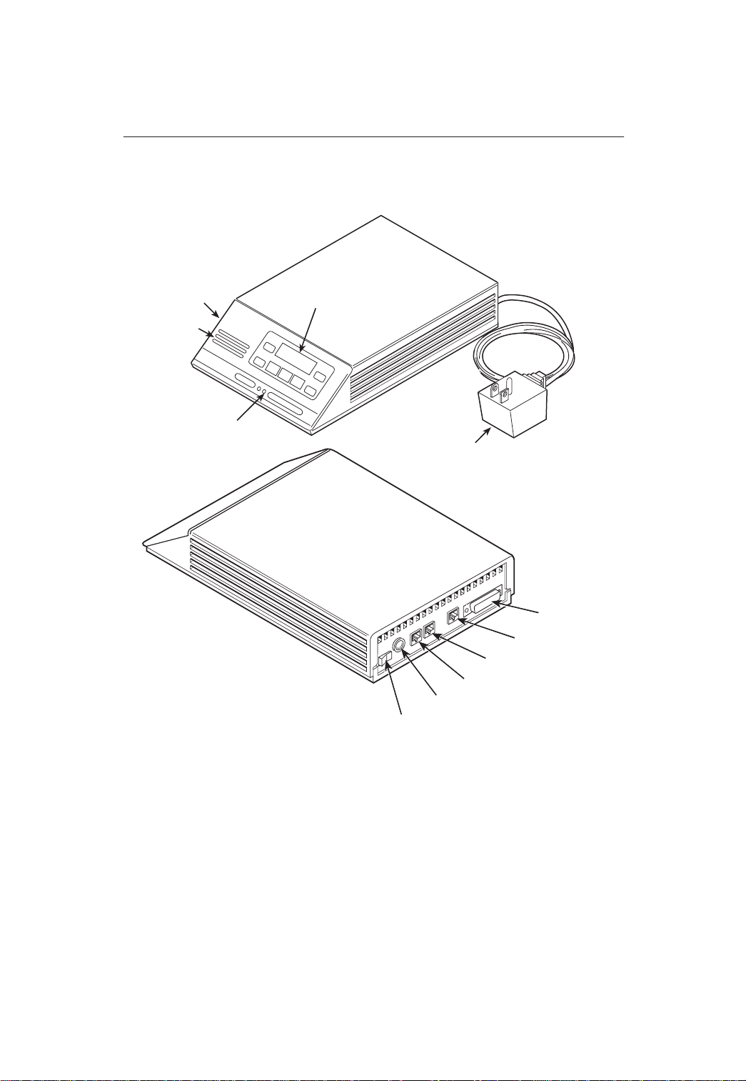
Models 3810 and 3820 Installation
DIAGNOSTIC
CONTROL
PANEL
SPEAKER
STATUS
INDICATORS
LCD AND KEYPAD
AC TRANSFORMER
EIA-232-D
INTERFACE
NMS
DIAL/LEASED (3820)
PHONE/LEASED (3810)
AC POWER IN
ON/OFF
496-13096-02
2
Page 5

Customer-Supplied Equipment for Models 3810 or 3820
The following customer-supplied equipment is required to complete a data
communications system using either the Model 3810 or Model 3820 modem:
A DTE with an available EIA-232-D serial port.
A standard EIA-232-D male-to-female cable with a male DB-25-S connector at one
end to attach to the modem.
One of the following modular dial or leased network interfaces:
— RJ11C for dial permissive applications
— An 8-position to 6-position crossover cable for JM8 leased-line applications
only
Model 3810 or 3820 Telephone Connection
Use the following procedures to connect the modem to a telephone:
1. Insert the 6-position, 4-conductor modular plug into the jack labeled
PHONE/LEASED (3810).
2. Insert the other end of the modular cord into the telephone.
Dial Network Management System Connection
For Model 3810 and 3820 modems, use the following procedures to connect the
modem to the network management system interface:
1. Insert the subminiature 4-conductor modular plug of the 3600 Hubbing Device into
the jack labeled NMS.
2. Connect the 3600 Hubbing Device to the network management system.
Refer to the
Instructions
3820 modems is the same as for the 3610 DSU.
3600 Hubbing Device, Feature Number 3600-F3-300, Installation
(3610-A2-GZ45) for more information. Installation for the Model 3810 and
AC Power Transformer Connection
Use the following procedures to connect the modem to an ac power outlet:
1. Make sure the modem’s power switch is in the Off position.
2. Insert the power transformer’s 5-pin DIN male connector into the modem’s rear
panel ac power receptacle.
3. Insert the power transformer into a grounded ac power outlet.
3
Page 6
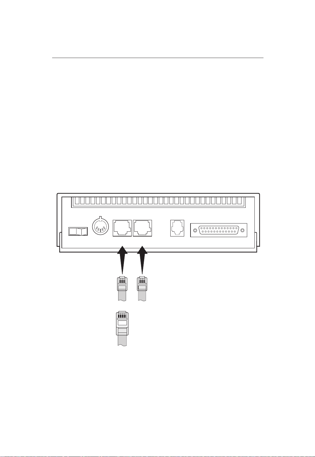
Model 3810 Dial Connection
For the Model 3810, use the following procedures to connect the modem to the dial
network interface:
1. Insert the 6-position, 4-conductor modular plug into the jack labeled DIAL/LEASED
(3820).
2. Insert the other end of the modular cord into the network interface.
Model 3810 Leased Line Connection
Use the following procedures to connect a Model 3810 to the 2-wire or 4-wire
leased-line network interface:
1. Insert the 8-position, 8-conductor modular plug into the jack labeled
PHONE/LEASED (3810).
2. Insert the other end of the modular cord into the leased-line network interface.
01
PWR
6-POSITION,
4-CONDUCTOR PLUG
FOR TELEPHONE SET
8-POSITION,
8-CONDUCTOR PLUG
FOR LEASED LINE
NETWORK OPERATION
(CONNECTS WITH
JM8 TYPE JACK)
PHONE DIAL NMS
(3810)
LEASED
(3820)
LEASED
6-POSITION, 4-CONDUCTOR PLUG FOR
PERMISSIVE DIAL NETWORK OPERATION
(CONNECTS WITH RJ11C TYPE JACK)
DTE
98-13070-02
4
Page 7
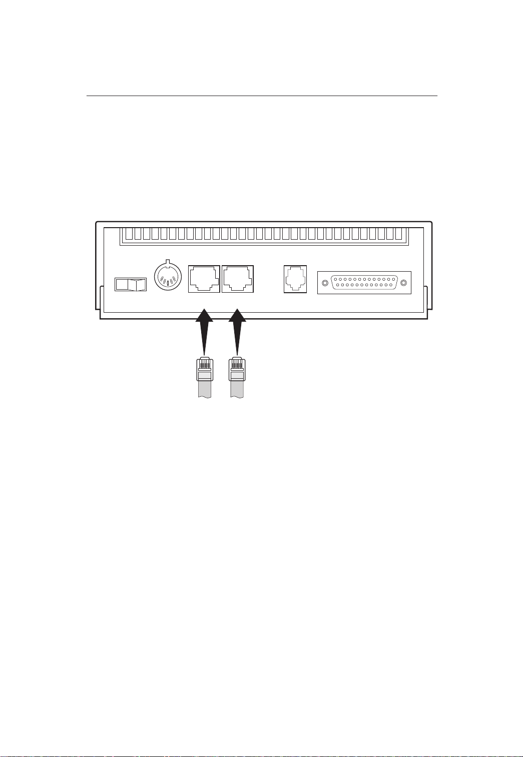
Model 3820 Network Connection
Use the following procedures to connect a Model 3820 to the dial or 2-wire leased-line
network interface:
1. Insert the 6-position, 4-conductor modular plug into the jack labeled DIAL/LEASED
(3820).
2. Insert the other end of the modular cord into the network interface.
01
PWR
6-POSITION,
4-CONDUCTOR PLUG
FOR TELEPHONE SET
PHONE DIAL NMS
(3810)
LEASED
(3820)
LEASED
6-POSITION, 4-CONDUCTOR PLUG FOR
PERMISSIVE DIAL NETWORK OPERATION
(CONNECTS WITH RJ11C TYPE JACK)
– OR –
2-WIRE LEASED-LINE NETWORK OPERATION
(CONNECTS WITH 6-POSITION CENTER PAIR
LEASED JACK)
DTE
98-13071-02
5
Page 8
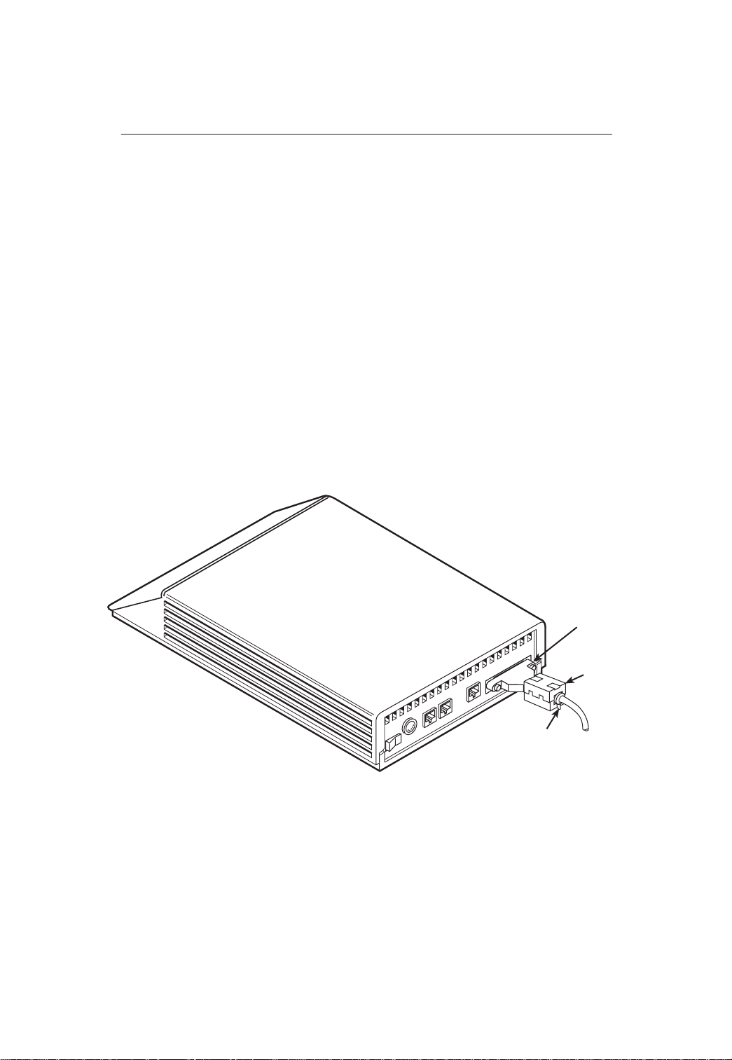
DTE Connection
Use the following procedures to connect the EIA-232-D cable and ferrite choke from
the modem to the DTE:
1. Make sure the modem’s rear panel power switch is Off.
2. Connect the DB-25 plug on the cable to the DB-25 socket labeled DTE on the
modem’s rear panel. Use a small screwdriver to fasten the cable to the modem.
3. Connect the other end of the cable to the DTE. Use a small screwdriver to fasten
the cable to the DTE.
To ensure compliance with FCC Part 15 Regulations, a ferrite choke must be installed
on the EIA-232-D interface cable.
1. Open the ferrite choke and place it around the DTE cable as close as possible to
the connector attached to the modem.
2. Close the two halves around the cable and snap the ferrite choke shut, pressing
down on the plastic latch to secure it.
3. Install a cable tie behind the ferrite choke to prevent it from sliding along the cable.
DTE
Connector
Ferrite
Choke
Cable Tie
98-13144-01
6
Page 9

Model 3811 Installation
FACEPLATE
Status
Pwr
Alrm
142
Test
Dial
125
RI
Busy
Serv
SQ
103
TXD
104
RXD
105
RTS
106
CTS
107
DSR
108
DTR
109
LSD
Front Panel
Spkr
EIA-232/V.24
CONNECTOR
EIA-232/V.24
EDGE CARD
CONNECTOR
RS-366A/V.25
EDGE CARD
CONNECTOR
REAR
CONNECTOR
PLATE
EIA232/V.24
(3800)
RS366A/V.25
RS-366A/V.25
CONNECTOR
(3600/3500)
V.35
3811
496-13155-02
7
Page 10

Customer-Supplied Equipment for Model 3811
The following customer-supplied equipment is required for the installation of a
Model 381 1 modem:
A COMSPHERE 3000 Series Carrier.
A male-to-female 50-pin mass termination cable. One Network Interface Module
(NIM) for modems installed in Slots 1–8 and one NIM for modems installed in Slots
9–16 (required for dial-line applications).
One of the following modular or 50-pin dial or leased network interfaces:
— RJ11C for single line dial permissive applications
— RJ21X for multiple line dial permissive applications
— 66 punchdown block or other demarcation device
One 6-position to 6-position modular cord (required for network management
applications).
A Shared Diagnostic Unit (SDU) (required for network management applications).
Model 3811 Installation
The Model 381 1 is designed for installation in a COMSPHERE 3000 Series Carrier
which supplies operating power and the dial and/or leased-line network connections.
For correct power, DTE, dial-line, leased-line, NIM, and network management cabling
information, refer to the
Document No. 3000-A2-GA31.
The installation of a Model 381 1 varies slightly if an SDCP is installed on the front of the
carrier. To install a Model 3811 modem into the carrier without an SDCP, perform the
following steps:
COMSPHERE 3000 Series Carrier, Installation Manual
,
CAUTION
If the Model 3811 is removed from the carrier, always use a ground
strap when handling the modem. Always store the Model 3811 in an
antistatic bag when it is removed from the carrier.
8
Page 11

1. At the rear of the carrier, install the rear connector plate. Make sure the plate uses
the same slot position as that intended for the modem.
— Loosely fasten the plate. This allows for slight adjustments later when
installing the modem.
2. At the front of the carrier, hold the modem vertically, with the latch on its faceplate
in the open position, and insert it into the top and bottom card guides of one of the
slots numbered 1–16.
— Slide the modem into the slot, aligning the modem with the rear connector
plate, until the backplane connector and DTE connector seat firmly into the
back of the carrier. The faceplate latch automatically closes as you push the
modem into the carrier. To lock the modem into the carrier, press the faceplate
latch until a click is heard.
3. If the carrier is ON, the Power LED on the faceplate of the 3811 lights. After
several seconds the modem completes its power-up self-test in which all faceplate
LEDs light. If the modem fails, the Alrm LED on the faceplate flashes.
— Return to the rear of the carrier and tighten the rear connector plate.
9
Page 12

If the modem is to communicate with an installed SDCP, install the modem as
described above and perform the following steps:
1. Press the
key on the SDCP. The cursor appears in the carrier selection
Select
entry .
2. Press the F1 () or F2 (↓) key until the carrier number you want appears on the
LCD.
3. Press the
key to position the cursor on the slot selection entry .
4. Press the F1 () or F2 (↓) key until the slot number (1–16) you want appears on
the LCD.
5. Press the
key to place the SDCP in direct communication with the
Select
selected modem.
— The LCD displays the Top-Level menu for the selected modem. In addition,
the Front Panel LED on the modem’s faceplate and the OK LED on the SDCP
light.
6. Once you have determined that the modem is installed properly and completed its
power-up self-test, rotate the circuit pack lock until it covers the faceplate latch.
This prevents the modem from accidently being removed once it is installed in a
carrier.
CLOSED
(LOCKED)
OPEN
(UNLOCKED)
CIRCUIT
PACK
LOCK
LATCH
CIRCUIT
CARD
GUIDE
CIRCUIT
CARD
GUIDE
495-11985a-03
10
Page 13

Diagnostic Control Panel (DCP) – Models 3810 and 3820
The DCP is the user interface to the modem. It provides a 2-line, 32-character liquid
crystal display (LCD), a keypad, speaker grill, and status indicators.
HIDDEN
SPEAKER
KEYPAD
Idle:19.2
Call_Setup
CHOICE
INDICATOR
COMSPHERE 3810
COMSPHERE 3820
STATUS INDICATORS
PWR ALRM
F1 F2
DTR
DIAG
CTS TXD LSD RXD TEST
108 142
105
RTS
105
109
103
106
CTS TXD LSD RXD
109
103
106
F3
SQRTS
RATE
104
SQ
104
11
Page 14

Shared Diagnostic Control Panel (SDCP) – Model 3811
The SDCP is used to manage carrier-mounted 381 1 modems. The Select key is used
to connect the SDCP to a modem or other device in a specific carrier and slot location.
Press the Select key, then enter the modem carrier (1–8) and slot (1–16) numbers. The
Front Panel LED lights up on the selected modem. Once the modem is selected,
operation of the SDCP is the same as for the standalone DCP.
Status
142
125
103
104
105
106
107
108
109
Front Panel
Direction and Function keys provide operator control.
Pwr
Alrm
Test
Dial
RI
Busy
Serv
SQ
TXD
RXD
RTS
CTS
DSR
DTR
LSD
and
F1, F2, F3
Hidden Choice Indicators.
Moves up one level from the current display.
Moves cursor or display to the left or right.
Returns display to Top-Level menu.
Selects item displayed directly above the key.
Indicates more LCD selections are available to the left or right of what is
Spkr
Nxt
currently displayed on the LCD.
Indicates more configuration options are available below what is currently
displayed. Also indicates selected configuration option.
End
3811
SDU12345678910111213141516
SELECT
KEY
OK Alarm BckUp Test EC
Indicates last configuration option available for that group.
CARRIER SLOTS 1–16
Select
OK Alarm BckUpTest EC
STATUS
INDICATORS
F1 F2 F3
KEYPAD
COMSPHERE 3000
LCD
NETWORK
DEVICE
ALARM
DIAL
BACKUP
CORRECTION
TEST
MODE
ERROR
12
Page 15

Configuration Option Procedures — DCP Commands
1. Move to the Configure branch and select a configuration area to load from: Active
(Operating), Active (Saved), Customer 1, Customer 2, or Factory (Async Dial,
Sync Dial, Sync Leased, or UNIX Dial). If Enhanced Throughput Cellular (ETC) is
installed, Factory areas Cellular (Mobile) and Cellular (PSTN) are also available.
Select Configure from the Top-Level menu.
Idle : 19.2
Test Configure
F1
F2
F3
Scroll to the area you wish to load.
Ld EditArea frm <
Factory
F1
F2
2. Select Edit to choose the set of configuration options to be edited: DTE Interface,
DTE Dialer, Line Dialer, Dial Line, Leased Line, V.42/MNP/Buffer, Tests, Misc, or
Security.
F3
Edit StrapGroup <
Test Misc
F1
F2
3. When the new configuration is completed, Save the edited configuration options to
the desired configuration area: Active (Saved), Customer 1, Customer 2.
F3
Sav EditArea to >
Active (Saved)
F1
F2
F3
13
Page 16

3800 Modems Menu Tree
“Status”
Call_Setup Tlk/Data Status Test
Dial
★
Answer
Disconnect
Directory Locations 1 – 10
Does not appear in Remote Mode.
(Rem_Digital_Loop, Loc_Digital_Loop, and
Pattern appear if the secondary channel is
used.)
Some choices within this group may not
appear depending upon how previous
configuration options have been selected.
Carrier model only.
Dial_Standby
Return_to_Dial
Change_Directory
or
VF Identity
SigQual
RcvLev
Sig/Noise
NearEcho
FarEcho
FarEchDel
EchoFreqOff
Abort Self
Ser#
Mod #
FRev
HPt#
FPt#
Displays current status of modem along with
data rate and error control mode.
DTE
LSD
DTR
DSR
Tst
TXD
RXD
RTS
CTS
Loc_Analog_Loop
★
RS366A
Options
CRQ
DLO
DPR
PND
DSC
ACR
Rem_Digital_Loop
to next page
Record
Pattern
Loc_Digital_Loop
to next page
DTE_Interface
Async/Sync Mode
Async DTE Rate
#Data Bits
Parity Bit
#Stop Bits
DTR Action
DSR Control
RTS Action
CTS Control
RTS/CTS Delay
LSD Control
TX Clock Source
CT111_Rate Cntl
DTE_Rate=VF
DTE_Dialer
DTE Dialer Type
AT Escape Char
Escape GuardTim
BreakForceEscap
CommandCharEcho
CarriageRtn Char
Backspace Char
Linefeed Char
Result Codes
ExtendResltCode
ResultCode Form
AT Cmnd Mode
V25bis Coding
V25bis IdleFill
V.25b NewLineChr
DTR Cont Repeat
14
Line_Dialer
AutoAnswerRing#
Dialer T ype
DialTone Detect
Blind Dial Paus
BusyTone Detect
"," Pause Time
NoAnswer Timout
Fast Disconnect
Line Crnt Disc
Long Space Disc
No Carrier Disc
No Data Disc
Auto Make Busy
MakeBusyViaDTR
DTR Auto Redial
Dial_Line
Dial Line Rate
19200(V32t)
16800(V32t)
14400(V32b)
12000(V32b)
9600(V32b)
7200(V32b)
4800(V32b)
2400(V22bis)
1200(V22)
1200(212A)
0–300(V21)
0–300(103J)
V32bis Automode
V32bis Autorate
Dial TX Level
V22b Guard Tone
V32bis T rain
FallFwdDelay
98-14436a-03
Page 17

from previous page
to next page
Configure
Ld EditArea frm:
from previous page
Leased_Line
Leased Mode
LeasedLine Rate
19200(V32t)
16800(V32t)
14400(V32b)
12000(V32b)
9600(V32b)
7200(V32b)
4800(V32b)
2400(V22bis)
V32bis Autorate
Leased TX Level
1800HzTrainTone
BdLn Auto Orig
Rate Auto Orig
Auto Redial
AutoDialStandby
CarrierOnLevel
FallFwdDelay
Activ (Operating)
Active (Saved)
V42/MNP/Buffer
Err Contrl Mode
V42/MNPorBfr
V42/MNPorDsc
MNP or Buffr
MNP or Disc
BufferMode
DirectMode
LAPM_or_Disc
LAPM_or_Buff
V42bis Compress
MNP5 Compress
EC Negotiat Bfr
EC Fallbck Char
Flw Cntl of DTE
Flw Cntl of Mdm
XON/XOFF Psthru
Mdm/Mdm FlowCtl
Break Buffr Ctl
Send Break Cntl
Tx Buff Disc Delay
Rx Buff Disc Delay
Max Frame Size
Cellular Enhance
Customer2 Factory
Customer1
Async_Dial
Choose Function
Edit Save
Active (Saved) Customer1 Customer2
Tests
DTE RL (CT140)
DTE LL (CT141)
Test Timeout
Rcv Remote Loop
V54 Address
V54 Device Type
✤
Sync_Dial
Answer Originate
Sync_Leased
Choose Mode
Misc
StrapsWhenDisc
Speaker Control
Speaker V olume
Access frm Remt
RemAccssPasswrd
Dir#1_Callback
NetMngmtAddress
NMS_Call_Msgs
NMS DTR Alarm
NetworkPosition
RJ11 Cellular Adapt
Does not appear if configured for
Synchronous mode
Only appears if Sync_Leased factory
template is selected.
Only appears if ETC is installed.
✤
Cellular (Mobile)
UNIX_Dial
✤
✤
Cellular (PSTN)
Security
EntryWait_Time
VF_Prompt_Type
#DTE_PW_Tries
DTE_PW_TermChar
DTE_PW_BkSpChar
Get_User_ID
NMS_Reporting
Answer_Secur
Originate_Secur
98-14436b-03
✤
15
Page 18

from previous page
Control Remote
Secondary Prim (data blckd)
instead of Remote when
Speaker
RemoveMakeBusy
Reset
Make_Busy
or
Service_Line
DiscServLine
(ExitRem appears
using Remote Mode)
Download Code
or
EditPassWdTable
Set_Access_Ctrl
(Admin Password?)
Set_Answer_Sec
Security
Reset_Security
Set_Orig_Secur
Set_Admin_PsWd
16
98-14436c-03
Page 19

Configuration Option Procedures — AT Commands
Loading Factory Configurations
Use the AT&Fy&Wn command to load a factory configuration to either the Active
(Saved), Customer 1, or Customer 2 configuration area.
Type: AT&F
where:y is one of the following factory configurations:
y&Wn
0 = Async Dial
1 = Sync Dial
2 = Sync Leased (Answer)
3 = UNIX Dial
4 = Sync Leased (Originate)
5 = Cellular (Mobile) (V alid only if ETC is installed)
6 = Cellular (PSTN) (Valid only if ETC is installed)
where:
n
is one of the following configuration areas:
0 = Active (Saved)
1 = Customer 1
2 = Customer 2
Loading Configuration Areas to Active (Operating)
Use the ATZn command to load stored configurations from Active (Saved), Customer 1,
or Customer 2 configuration areas to Active (Operating).
Type: ATZ
where:n is one of the following:
n
0 = Active (Saved)
1 = Customer 1
2 = Customer 2
3 = Active (Saved) + Reset
17
Page 20

AT COMMANDS
Bold text indicates Async Dial factory defaults.
AT Attention Command Prefix/Autobaud
A/ Repeat Last Command. Re-executes
A Answer Mode. Goes off-hook and
B
B0 V.21 or V .22 (300 or 1200 bps).
B1 Bell 103 or 212A (300 or 1200 bps).
D
DS=nDial Stored Number. Dials the number
En Command Character Echo
E0 Disables echo to the DTE.
E1 Enables echo to the DTE.
H0 Modem goes on-hook.
H1 Modem goes off-hook.
I0 Displays product code–144.
I1 Displays 3-digit firmware revision
I2 Performs an EPROM check.
I3 Displays modem’s serial number.
I4 Displays modem’s model number.
I5 Displays part number of circuit card.
I6 Displays firmware release number.
I9 (same as I1)
I10=
I11 Firmware checksum.
I19 Displays entire firmware revision number.
Ln Speaker Volume
L0,L1 Selects low volume.
L2 Selects medium volume.
L3 Selects high volume.
Mn Speaker ON/Off Control
M0 Speaker always Off.
M1 Speaker ON until carrier signal
M2 Speaker always ON.
O Returns modem to Data mode from
P Enables Pulse Dial mode.
Rate. Indicates a command string has
started and determines the DTE’s data
rate and parity.
last command string. (Not to be
preceded with AT or followed by pressing
Enter.)
attempts to establish a connection
without waiting for a ring.
n ITU-T/Bell Mode
n
Dial. Dials the telephone number entered
for
n.
stored in location
number.
n
Changes value of product code (0=144,
1=240, 2=480, 3=960, 4=120).
becomes active.
online Command mode.
n
(1–10).
AT COMMANDS (continued)
Qn Result Codes
Q0 Enables result codes. Refer to
Q1 Disables result codes.
Q2 Enables originate modem to send result
S
r
S
r=n
T Enables Tone Dial mode.
Codes
section.
codes to the DTE. Required for most
UNIX applications.
? Displays value of S-Register (where r is
the register number).
Change S-Register . Changes the
contents of the S-Register (where r is the
register number and
value).
n
is the assigned
Vn Result Code Format
V0 Displays as digits (Numbers 1).
V1 Displays as text.
V2 Displays as digits (Numbers 2).
Xn Extended Result Codes; Dial Tone
Detect; Busy Tone Detect
X0 Disables extended result codes 5–16,
X1 Enables extended result codes 5–16,
X2 Enables extended result codes 5–16, dial
X3 Enables extended result codes 5–16,
X4 Enables extended result codes 5–16,
X5 Adds EC suffix to extended result codes
X6 Adds either V.42 or MNP suffix to
X7 DTE rate appears in CONNECT
dial tone detect, and busy tone.
disables dial tone detect and busy tone
detect. Refer to
tone detect, and disables busy tone
detect.
disables dial tone detect and enables
busy tone detect. Refer to
section.
dial tone detect, and busy tone detect.
Refer to
(20–27) if error control is used, enables
dial tone detect and busy tone detect.
extended result codes (20–27) if data
compression is used, enables dial tone
detect, and busy tone detect.
message instead of line rate, enables dial
tone detect and busy tone detect. Refer
to
Result Codes
Result Codes
Result Codes
section.
section.
Yn Long Space Disconnect
Y0 Disable.
Y1 Enable.
Zn Reset and Load Active
Z0 Loads contents of Active (Saved) into
Z1 Loads contents of Customer 1 into Active
Z2 Loads contents of Customer 2 into Active
Active (Operating).
(Operating).
(Operating).
Result
section.
Result Codes
18
Page 21

AT COMMANDS (continued)
Z3 Loads contents of Active (Saved) into
Active (Operating) and performs a reset.
Z9 Performs a full modem reset.
&Cn LSD Control
&C0 Forced On. Forces LSD ON at all times.
&C1 Standard RS232. LSD is ON when the
remote modem’s carrier signal is
detected. LSD is Off when carrier
signal is not detected.
&C2 Wink When Disc. LSD, normally forced
ON, turns Off for approximately 1 to 2
seconds upon disconnect.
&C3 Follows DTR. State of LSD follows state
of DTR.
&C4 Simulated Control Carrier. State of LSD
follows state of remote modem’s RTS.
&C5 =DTR/DiscOff. State of LSD follows
state of DTR except upon a disconnect
where DTR remains ON and LSD turns
Off. DTR must then toggle Off and ON to
turn LSD ON. Required for AT&T
DATAKIT dial-out applications.
&C6 Bridge Retrain. LSD behaves as in
Standard RS232, except that it is turned
Off when retrain lasts longer than 10
seconds, and ON when no retrain is
detected for 10 seconds.
&Dn DTR Action
&D0 Ignore. Modem ignores the DTR (Data
Terminal Ready) signal and treats it as
always ON.
&D1 Off=Command Mode. Modem enters
online Command mode when DTR is
lowered.
&D2 Standard RS232. DTR signal is
controlled by the DTE.
&D3 Off=Reload Straps. Modem loads Active
(Operating) area with Active (Saved)
area when DTR is lowered.
&D4 Controls On-Hook. Modem does not
disconnect until DTR lowered by DTE.
&D5 Controls Tx Mute. Transmitter output
muted when DTR is lowered.
&Fn Loads Factory Configuration
&F0 Loads Async Dial factory configuration
options into Active (Operating)
configuration area.
&F1 Loads Sync Dial factory configuration
options into Active (Operating)
configuration area.
&F2 Loads Sync Leased (Answer Mode)
factory configuration options into Active
(Operating) configuration area.
&F3 Loads UNIX Dial factory configuration
options into Active (Operating)
configuration area.
&F4 Loads Sync Leased (Originate Mode)
factory configuration options into Active
(Operating) configuration area.
&F5 Cellular (Mobile). Valid only if ETC is
installed.
AT COMMANDS (continued)
&F6 Cellular (PSTN). Valid only if ETC is
&Gn V.22bis Guard T one
&G0 Disables guard tone.
&G1 Sets guard tone to 550 Hz.
&G2 Sets guard tone to 1800 Hz.
&In Dial T ransmit Level
&I10 –10 dBm.
&I11 –1 1 dBm.
• •
• •
I32 –32 dBm.
&
&I99 ETC 1.0 (Cellular). Valid only if ETC is
&
I100 ETC 1.1 (Cellular). Valid only if ETC is
&Jn Dial Transmit Level T ype
&J0 Modem sets dial transmit level to
&Ln Leased-Line Mode
&L0 Disables leased-line operation.
&L1 2-wire originate leased-line operation.
&L2 4-wire originate leased-line operation.
&L3 2-wire answer leased-line operation.
&L4 4-wire answer leased-line operation.
&Mn,&Qn Async/Sync Mode and DTE Dialer Type
&M0,&Q0 Modem operates in Asynchronous
&M1,&Q1 Modem operates in Synchronous mode
&M2,&Q2 Modem operates in Synchronous mode
&M3,&Q3 Modem operates in Synchronous mode
&Q4 Modem operates in Asynchronous mode
&M231, &Q231 Modem operates in Asynchronous
&M232, &Q232 Modem operates in Asynchronous
&M233, &Q233 Modem operates in Synchronous
&M234, &Q234 Modem operates in Synchronous
&M235, &Q235 Modem operates in Asynchronous
&M236, &Q236 Modem operates in Synchronous
&Rn RTS Action
&R0 Standard RS232. RTS action is
&R1 Ignores RTS. Modem ignores RTS
installed.
installed.
installed.
Permissive mode at –9 dBm.
mode and uses AT command protocol.
and uses AT command protocol.
and dials telephone number stored in
directory location 1 when DTR signal
turns Off and then ON.
and uses AT command protocol.
and uses AT Command protocol; Hayes
AutoSync is enabled.
mode; the DTE Dialer Type is disabled.
mode; V.25bis Async dialing is enabled.
mode; V.25 Bisync dialing is enabled.
mode; V.25bis HDLC dialing is enabled.
mode; AT&T Exclusive dialing is enabled.
mode; the DTE Dialer Type is disabled.
controlled by DTE.
signal and treats it as always ON.
19
Page 22

AT COMMANDS (continued)
&R2 Simulated Control Carrier. State of RTS
follows state of LSD.
&Sn DSR Control
&S0 Forced On. Forces DSR signal ON.
&S1 Standard RS232. Modem controls DSR
signal.
&S2 Wink When Disc. DSR signal turns Off
for approximately 1 to 2 seconds upon
disconnecting.
&S3 Follows DTR. Modem sends DSR to DTE
when it receives DTR from DTE.
&S4 On Early. DSR is Off when modem is in
idle state. DSR goes ON when modem
enters Data mode.
&S5 Delay to Data. DSR does not turn ON
until the modem enters Data mode.
&S6 Dial Backup toggle.
&Tn Tests
&T0 Stops any test in progress.
&T1 Starts a Local Analog Loopback test
(V.54, L3).
&T2 Transmits and receives a 511 BERT
pattern.
&T3 Starts a Local Digital Loopback test.
&T4 Accepts request from remote modem for
a Remote Digital Loopback test.
&T5 Denies request from remote modem for a
Remote Digital Loopback test.
&T6 Starts a Remote Digital Loopback test
(V.54, type L2).
&T7 Starts a Remote Digital Loopback test
with a Pattern (V.54, type L2).
&T8 Starts a Local Analog Loopback test
with a Pattern (V.54, type L3).
&T9 Starts a self-test.
&Vn View Configuration Options
&V0 Displays Active (Operating) configuration
options.
&V1 Displays Active (Saved) configuration
options.
&V2 Displays Customer 1 configuration
options.
&V3 Displays Customer 2 configuration
options.
&V4 Displays telephone numbers stored in
directory locations 1–10.
&Wn Write (Save to Memory)
&W0 Saves current configuration options in
Active (Operating) to Active (Saved).
&W1 Saves current configuration options in
Active (Operating) to Customer 1.
&W2 Saves current configuration options in
Active (Operating) to Customer 2.
&Xn Transmit Clock Source
&X0 Modem provides internal clock source
for synchronous data (Pin 15).
&X1 Modem uses external source (Pin 24) for
clock for synchronous data.
AT COMMANDS (continued)
&X2 Modem uses received signal as clock
&Z
\
An Maximum Frame Size
\A0 64
\A1 128
\A2 192
\A3 256
\A4 32
\A5 16
\Cn Error Control Negotiate Buffer
\C0 Data is not buffered during
\C1 Data is buf fered up to 4 seconds during
\C2 Data is not buf fered during handshaking
\Dn CTS Control
\D0 Forced On. CTS is forced ON.
\D1 Standard RS232 operation.
\D2 Wink When Disc. CTS turns Of f for
\D3 Follows DTR. The state of CTS follows
\Gn Modem-to-Modem Flow Control
\G0 Disables modem-to-modem flow
\G1 Enables modem-to-modem flow control.
\Kn Break Buffer Control, Send Break
\K0 Discards data, sends break before data,
\K1 Discards data, sends break before data,
\K2 Keeps data, sends break before data,
\K3 Keeps data, sends break before data,
\K4 Keeps data, sends data before break,
\K5 Keeps data, sends data before break,
\K6 Discards break, disables break forces
\Nn Error Control Mode
\N0 Buffer Mode. Modem does not use error
source for synchronous data.
n=x
Modem stores telephone number x (and
any dial modifiers) in directory location
(1–10). For example, the command
AT&Z1=555-1234 stores the number
5551234 in directory location 1. T o clear
a telephone number from a memory
location, issue &Z
telephone number.
handshaking sequence.
handshaking sequence.
sequence; however, the modem switches
to Buffer mode when it receives an error
control fallback character.
approximately 1 to 2 seconds upon
disconnecting.
the state of DTR.
control.
n=x
without entering a
Control, Break Forces Escape
and enables break forces escape.
and disables break forces escape.
and enables break forces escape.
and disables break forces escape.
and enables break forces escape.
and disables break forces escape.
escape.
control; DTE rate can differ from VF rate.
n
20
Page 23

AT COMMANDS (continued)
\N1 Direct Mode. Modem does not use error
\N2 MNP or Disc. Modem disconnects if it
\N3 MNP or Buf fer. Modem connects in
\N4 V.42/MNP or Disc. Modem disconnects if
\N5 V.42/MNP or Buffer. Modem connects
\N6 LAPM or disconnect.
\N7 LAPM or buf fer.
\Qn Flow Control of DTE
\Q0, \Q5, \Q6
\Q1, \Q4 Enables XON/XOFF flow control.
\Q2, \Q3 Modem raises and lowers CTS to start
\Qn Flow Control of Modem
\Q0, \Q2, \Q4
\Q1, \Q5 Enables XON/XOFF flow control.
\Q3, \Q6 Modem starts and stops flow control
\Tn No Data Disconnect T imer
\T0 Disables no data disconnect timer.
\Tn Sets no data disconnect timer to a value
\Xn XON/XOFF Passthrough
\X0 Disables transmission of flow control
\X1 Enables transmission of flow control
%A
%B
%Cn MNP 5 Data Compression
%C0 Disables MNP5 data compression.
%C1 Enables MNP5 data compression.
%R
H0 Disables V.42bis data compression.
H1 Enables V.42bis data compression for
H2 Enables V.42bis data compression for
H3 Enables V.42bis data compression
control; DTE rate and VF rate must be
the same.
does not connect in MNP mode.
Buffer mode if it does not connect in MNP
mode.
it does not connect in V.42 or MNP mode.
in Buffer mode if it does not connect
in V.42 or MNP mode.
Disables flow control of DTE.
and stop flow control.
Disables flow control of modem.
based upon state of DTE’s RTS signal.
from 1 minute to 255 minutes.
characters to remote modem.
characters to remote modem.
n
Sets error control fallback character n to
an ASCII value from 0 to 127.
n
Sets data rate to n (300 to 19200).
n
Sets DTE rate to n (300 to 115200).
Hn V.42 bis Data Compression
transmit only.
receive only.
in both the transmit and receive
directions.
RESULT CODES
Numbers(1) Numbers(2) Words
0 0 OK
1 1 CONNECT
2 2 RING
3 3 NO CARRIER
4 4 ERROR
Result Codes 5–14, 16, 19 are enabled with the X1,
X2, X3, and X4 commands.
5 5 CONNECT 1200
6 6 NO DIALTONE
7 7 BUSY
8 8 NO ANSWER
10 10 CONNECT 2400
11 11 CONNECT 4800
12 12 CONNECT 9600
13 16 CONNECT 12000
14 13 CONNECT 14400
15 14 CONNECT 19200
16 15 CONNECT 7200
17 17 CONNECT 16800
19 19 CONNECT 300
Result Codes 20–27 are enabled with the X5
command (EC suffix) or the X6 command (V.42 or
MNP suffix).
20 10 CONNECT 2400/EC
21 11 CONNECT 4800/EC
22 12 CONNECT 9600/EC
23 16 CONNECT 12000/EC
24 13 CONNECT 14400/EC
25 17 CONNECT 16800/EC
26 15 CONNECT 7200/EC
27 5 CONNECT 1200/EC
29 14 CONNECT 19200/EC
Result Codes 15, 28–34 are enabled with the X7
command (DTE rate suffix).
28 28 CONNECT 38400
30 30 CONNECT 57600
32 32 CONNECT 76800
34 34 CONNECT 115200
DIAL COMMAND MODIFIERS
T Tone Dial (DTMF)
P Pulse Dial
, Pause
W Wait for Dial Tone
R Reverse Dial
@ Quiet Answer
! Hook Flash
; Return to Command Mode
21
Page 24

S-REGISTERS
Register Description Factory Setting Range
S0 Auto-Answer Ring Number 1 0(Disable) or 1–255 rings
S2 AT Escape Character 43(+) 0–127 ASCII
S3 Carriage Return Character 13 0–127 ASCII
S4 Line Feed Character 10 0–127 ASCII
S5 Backspace Character 8 0–127 ASCII
S6 Blind Dial Pause 2 2–255 seconds
S7 No Answer Time-out 45 1–255 seconds
S8 “,” Pause T ime for the Dial Modifier 2 0–255 seconds
S10 No Carrier Disconnect 2 0–254 (10ths of a second) or 255(Disable)
S12 Escape Guard Time 50 0–255 in 20-millisecond increments
S18 Test Time-out 0(disabled) 0–255 seconds
S26 RTS/CTS Delay 0 0–255 seconds
S34 1800 Hz Training T one 0 0(Disable); 1(Enable)
S35 Auto Redial (Leased Line) 0 0(Disable) or 1(dirs 1–2) – 9(dirs 1–10)
S36 Rate Auto Originate 0 0(Disable) or 1(4800) – 6(16,800)
S37 Auto Redial (DTR) 0 0(Dir 1) – 9(Dirs 1–10)
S38 DTR Cont Repeat 0 0=Disable, 1=Enable
S39 Receive Buffer Disconnect Delay 0 0(Disable) or 1–255 seconds
S40 Auto Make Busy 0 0=Disable, 1=Enable
S41 Dial Line Rate 21 1=14400(V.32bis); 2=12000(V.32bis);
S43 V.32bis Train 0 0=Long; 1=Short
S44 Leased-Line Rate 18 1=14400(V .32bis); 2=12000(V.32bis);
S45 Leased TX Level 0 0 dBm–15 dBm
S46 Bad Lines Auto Originate 0 0=Disable; 1=30 seconds; 2=20 seconds;
S47 Auto Dial Standby 0 0=Disable; 1=15 minutes; 2=1 hour; 3=4 hours;
S48 Leased-Line Carrier On Level 0 0=–43 dBm; 1=–26 dBm
S49 Transmit Buffer Disconnect Delay 10 0=Disable or 1–255 in 1-second increments
S51 DTE RL (CT140) 0 0=Disable; 1=Enable
S52 DTE LL (CT141) 0 0=Disable; 1=Enable
S53 V.54 Address 0 0(Disable) or 1–34
3=9600(V .32bis); 4=7200(V .32bis);
5=4800(V .32bis); 6=2400(V .22bis); 7=1200(V.22);
8=1200(212A); 10=0–300(V.21); 11=0–300(103J);
20=19200(V .32terbo); 21=16800(V .32terbo)
3=9600(V .32bis); 4=7200(V .32bis);
5=4800(V .32bis); 6=2400(V22bis);
18=19200(V .32terbo); 19=16800(V .32terbo)
3=60 seconds; 4=90 seconds; 21=600 seconds
255=Test(2min)
22
Page 25

S-REGISTERS (continued)
Register Description Factory Setting Range
S54 V.54 Device Type 0 0=Peripheral; 1=Intermediate
S55 Access from Remote 0 0=Enable; 1=Disable
S56 Remote Access Password 00 00–99
S57 Remote Access Password 00 00–99
S58 Remote Access Password 00 00–99
S59 Remote Access Password 00 00–99
S61 CT111 Rate Control 0 0=Disable; 1=Fallback 1; 2=Fallback 2
S62 V.25bis Coding 0 0=ASCII; 1=EBCDIC
S63 V.25bis Idle Character 0 0=Mark; 1=Flag
S64 V.25bis New Line Character 0 0=CR+LF; 1=CR; 2=LF
S65 Line Current Disconnect 0 0=Enable (>8 msec); 1=Enable (>90 msec);
S66 NMS Call Messages 0 0=Call Connect & Progress; 1=Disable;
S67 Directory Location 1 Callback 0 0=Disable; 1=Enable
S69 Make Busy Via DTR 0 0=Disable; 1=Enable
S74 Network Position 0 0=Tributary; 1=Control
S75 Network Management Address 255 0–255 (001–256)
S76 V.32bis Dial Autorate 0 0=Enable; 1=Disable; 2=Start at 4800 bps;
S77 DTR Alarm Reporting 0 0=Disable; 1=Enable
S78 V.32bis Dial Automode 0 0=Enable; 1=Disable; 2=System85
S80 No Data Disc Trigger Signal 3 0=RX or TX; 1=TX; 2=RX; 3=TX and RX
S81 Leased Line Signal Quality Retrain 0 0(Disable) or 1–5 seconds
S82 V.32bis Leased Autorate 0 0=Enable; 1=Disable
S84 AT Command Mode 0 0=Normal; 1=No Error; 2=No Strap or ERROR
S85 Fast Disconnect 0 0=Disable; 1=Enable
S88 Straps When Disconnected 0 0=No Change; 1=Reload; 2=Reload, No Change
S89 V.42 ARQ Window Size Increase 0 0(6 frames) – 9(15 frames)
S90 DTE Rate = VF Rate 0 0=Disable; 1=Enable
S91 Cellular Enhancements 0 0=Disable; 1=Enable
S93 RJ11 Cellular Adapt 0 0=Disable; 1=Enable
1st and 2nd digits
3rd and 4th digits
5th and 6th digits
7th and 8th digits
2=Disable
2=Call Connect Only; 3=Call Progress Only
3=Start at 9600 bps
23
 Loading...