

Page 1

AREA CODE CHANGE
Please note that the area
code for Paradyne
Corporation in Largo,
Florida has changed from
813 to 727.
For any Paradyne
telephone number that
appears in this manual
with an 813 area code,
dial 727 instead.
Page 2

COMSPHERE
6700 SERIES
NETWORK MANAGEMENT
SYSTEM
SNMP PROXY AGENT
FEATURE
USER’S GUIDE
Document No. 6700-A2-GB20-10
Page 3

COMSPHERE
6700 Series
Network Management System
SNMP Proxy Agent Feature
User’s Guide
6700-A2-GB20-10
Issue 2 (December 1996)
Changes and enhancements to the product and to the information herein will be documented
and issued as a new release.
Warranty, Sales, and Service Information
Contact your sales or service representative directly for any help needed. For additional
information concerning warranty, sales, service, repair, installation, documentation or
training, use one of the following methods:
• Via the Internet: Visit the Paradyne World Wide Web site at
http://www.paradyne.com
• Via Telephone: Call our automated call system to receive current information via fax
or to speak with a company representative.
— Within the U.S.A., call 1-800-870-2221
— International, call 813-530-2340
Trademarks
All products and services mentioned herein are the trademarks, service marks, registered
trademarks or registered service marks of their respective owners.
COPYRIGHT 1996 Paradyne Corporation.
All Rights Reserved
Printed in U.S.A.
This publication is protected by federal copyright law. No part of this publication may be copied
or distributed, transmitted, transcribed, stored in a retrieval system, or translated into any
human or computer language in any form or by any means, electronic, mechanical, magnetic,
manual or otherwise, or disclosed to third parties without the express written permission of
Paradyne Corporation, 8545 126th Avenue North, P.O. Box 2826, Largo, Florida 33770–2826.
Paradyne Corporation makes no representation or warranties with respect to the contents
hereof and specifically disclaims any implied warranties of merchantability or fitness for a
particular purpose. Further , Paradyne Corporation reserves the right to revise this publication
and to make changes from time to time in the contents hereof without obligation of Paradyne
Corporation to notify any person of such revision or changes.
A Issue 2 December 1996
Page 4

Preface
Related Documents v. . . . . . . . . . . . . . . . . . . . . . . . . . .
Ordering Information vi. . . . . . . . . . . . . . . . . . . . .
1 Overview
What is SNMP? 1-1. . . . . . . . . . . . . . . . . . . . . . . . . . . . . .
What is the SNMP Proxy Agent Feature? 1-1. . . . . . . .
Software Description 1-2. . . . . . . . . . . . . . . . . . . . . . . . .
Feature List 1-2. . . . . . . . . . . . . . . . . . . . . . . . . . . . . . . . . .
Sample SNMP Network Topology 1-3. . . . . . . . . . . . . . .
SNMP Proxy Agent Feature Package Contents 1-4. . .
2 Installation
Hardware and Software Requirements 2-1. . . . . . . . . .
Supported Network Adapters 2-1. . . . . . . . . . . . . .
Preparing for Installation and Configuration 2-3. . . . . .
Installing the SNMP Proxy Agent Feature 2-5. . . . . . . .
Configuring the SNMP Proxy Agent Feature for
TCP/IP Networks 2-8. . . . . . . . . . . . . . . . . . . . . . . .
Issue 2 December 1996
i
Page 5

3 Management Information Bases
MIB-II Support 3-1. . . . . . . . . . . . . . . . . . . . . . . . . . . . . . .
MIB-II System Group Overview 3-2. . . . . . . . . . . .
MIB-II Interface Group Overview 3-2. . . . . . . . . . .
COMSPHERE 6700 Series NMS
Enterprise MIBs 3-3. . . . . . . . . . . . . . . . . . . . . . . . .
COMSPHERE 6700 NMS MIB Overview 3-5. . . .
COMSPHERE 6700 Device MIB Overview 3-5. .
Front Panel MIB Overview 3-6. . . . . . . . . . . . . . . .
Call Directory MIB Overview 3-6. . . . . . . . . . . . . .
DOS, Windows, and Workstation MIBs 3-6. . . . . . . . . .
SNMP Traps Overview 3-7. . . . . . . . . . . . . . . . . . . . . . . .
Device Traps 3-7. . . . . . . . . . . . . . . . . . . . . . . . . . . . . . . . .
SNMP Community Views 3-11. . . . . . . . . . . . . . . . . . . . . .
Community Name Example 3-11. . . . . . . . . . . . . . .
A MIB Definition
B Device Enterprise MIB Definition
C Enterprise Trap Definitions
D Enterprise Common MIB Definitions
Glossary
Refer to Document No. 6700-A2-GB22-00.
Index
ii Issue 2 December 1996
Page 6

Figures
1 Overview
1-1 Sample SNMP Network Topology 1-3. . . . . . . . . .
2 Installation
2-1 Welcome Window 2-5. . . . . . . . . . . . . . . . . . . . . . . .
2-2 Product Information Window 2-6. . . . . . . . . . . . . .
2-3 Destination Directory Window 2-6. . . . . . . . . . . . .
2-4 Confirmation Window 2-7. . . . . . . . . . . . . . . . . . . . .
2-5 Completion Status Window 2-7. . . . . . . . . . . . . . . .
2-6 Installation Completed! Window 2-8. . . . . . . . . . . .
3 Management Information Bases
3-1 SMI Defined Object Identifier Prefix Tree 3-4. . . .
Issue 2 December 1996
iii
Page 7

Tables
2 Installation
2-1 Supported Network Adapter Boards 2-2. . . . . . . .
3 Management Information Bases
3-1 MIB Browser Output Table 3-2. . . . . . . . . . . . . . . .
3-2 Primary Alert Traps 3-8. . . . . . . . . . . . . . . . . . . . . .
3-3 System Security Event Traps 3-9. . . . . . . . . . . . . .
3-4 Primary Alert Clear Notifications 3-10. . . . . . . . . . .
iv Issue 2 December 1996
Page 8

Preface
This guide describes how to install and use the COMSPHEREr
6700 Series Network Management System (NMS) SNMP Proxy
Agent feature.
This manual assumes you have a basic understanding of
COMSPHERE modems and data service units (DSUs) and their
operation, are knowledgeable about data communications, and
are familiar with Windowst terminology and conventions.
Related Documents
Contact your sales representative for additional product
documentation.
3510-A2-GA31
3610-A2-GB41
3610-A2-GB91
3610-A2-GN32
3810-A2-GB91
COMSPHERE 3000 Series Carrier, Installation
Manual
COMSPHERE 3600 Series Data Service Units,
Models 3610 and 3611, Time Division
Multiplexer, Multichannel Multipoint, and Digital
Bridge Options, Applications Guide
COMSPHERE 3600 Series Data Service Units,
Models 3610 and 3611, Operator’s Guide (with
Reference Card insert)
COMSPHERE 3600 Series Data Service Units,
Models 3610 and 3611, Dial Backup Module
and SNA Diagnostic Interface Options,
Applications Guide
COMSPHERE 3800 Series Modems, Models
3810, 3811, and 3820, User’s Guide
Issue 2 December 1996
v
Page 9

Preface
3910-A2-GN32
6700-A2-GB21
6700-A2-GB22
6700-A2-GB41
6700-A2-GY31
1001-40-1940
COMSPHERE 3900 Series Modems, Models
3910 and 3911, Point–to–Point/Multipoint,
Installation and Operation Manual
COMSPHERE 6700 Series Network
Management System Multiuser Feature User’s
Guide
COMSPHERE 6700 Series Network
Management System Network Configuration
Guide
COMSPHERE 6700 Series Network
Management System Security Manager
Feature Supplement
COMSPHERE 6700 Series Network
Management System User’s Guide
NEWT TCP/IP for Windows Installation and
User’s Guide
vi Issue 2 December 1996
Page 10

Overview
1
What is SNMP?
Simple Network Management Protocol (SNMP) is an Internet
standard protocol for managing TCP/IP devices.
Using SNMP, a network administrator can address queries and
commands to network nodes and devices. You can use SNMP
to monitor network performance and status; control operational
parameters; and report, analyze, and isolate faults.
Agents, managers, and Management Information Bases
(MIBs) combine to control network devices.
Agents collect management information and store it in a
database called the MIB. The agent provides management
information to an SNMP manager upon request.
Non-TCP/IP devices can be managed with SNMP proxy agents.
What is the SNMP Proxy Agent
Feature?
The COMSPHEREr 6700 Series Network Management System
SNMP Proxy Agent feature provides the capability for any
device managed by a COMSPHERE 6700 Series Network
Management System (NMS) to also be monitored and controlled
by an SNMP network management system, such as HP
OpenViewt or SunNett Manager.
Issue 2 December 1996
1-1
Page 11

Overview
Software Description
The SNMP Proxy Agent feature includes NetManage Enhanced
Windows TCP/IP (NEWTt) software, which supports
transmission of SNMP messages across Ethernetr, Token Ring,
FDDI, SLIP, and PPP interfaces.
The SNMP Proxy Agent feature is a software package that can
be installed on top of the COMSPHERE 6700 Series NMS
Release 4.0.0 or higher at any time.
NOTE:
COMSPHERE 6700 Series NMS Release 4.0.0 or higher
is required to execute the SNMP Proxy Agent feature.
You can install the SNMP Proxy Agent feature in any of the
following COMSPHERE 6700 Series NMS installations:
G Single user
G Multiuser server
G Multiuser client
Feature List
The SNMP Proxy Agent feature provides the following features:
G SNMP Proxy Agent for COMSPHERE devices using
Enterprise MIBs
G SNMP Agent for COMSPHERE 6700 Series NMS using
Enterprise MIBs
G SNMP Agent for MIB-II
G SNMP Agent for DOS, Windowst, and workstations
using NetManage Enterprise MIBs
G COMSPHERE 6700 Series NMS Alerts exported as
SNMP Traps
G One IP address per COMSPHERE 6700 Series NMS
G Specific Community View Access for each managed
device
1-2 Issue 2 December 1996
Page 12
Overview
Integrated TCP/IP, UDP/IP, and SNMP Protocol support
Concurrent Ethernet, Token Ring, FDDI, SLIP, and PPP
interface support
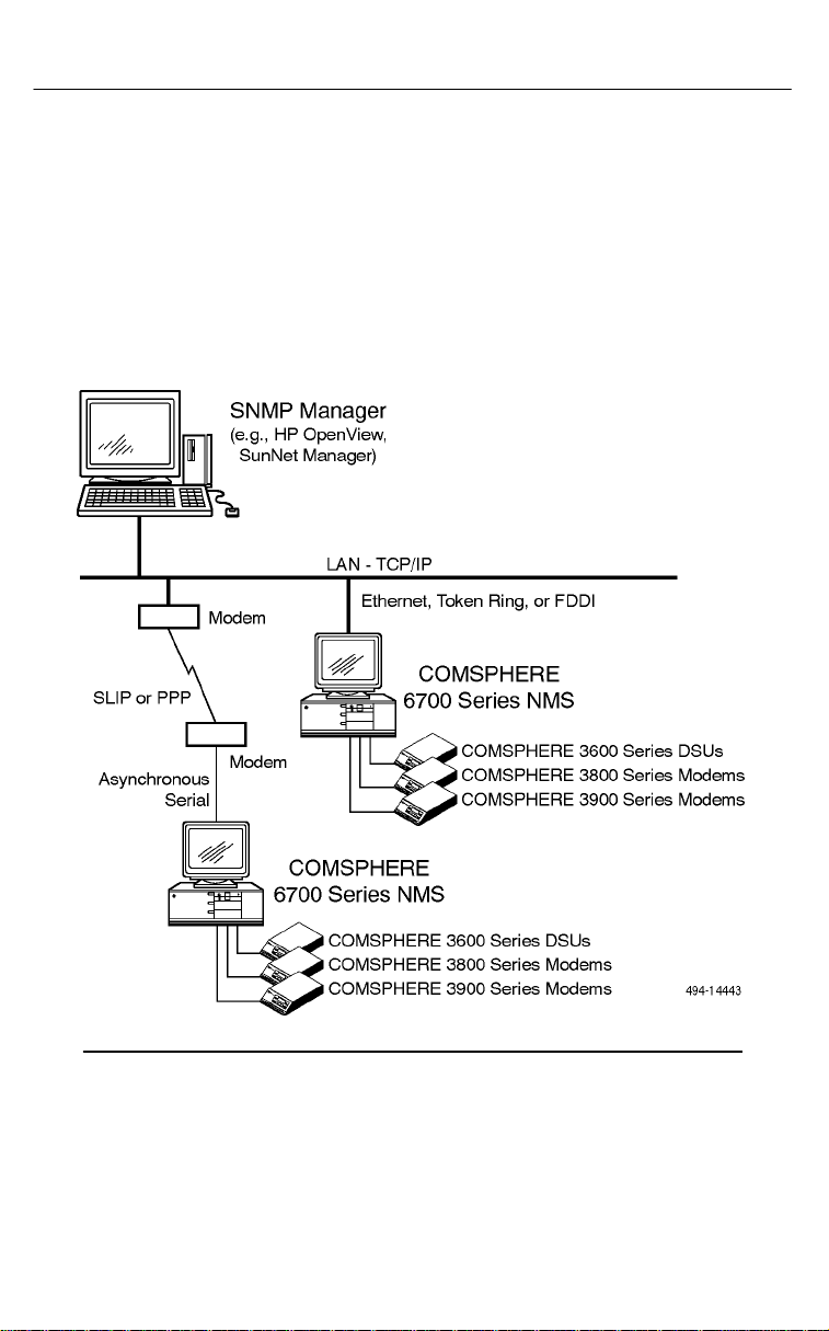
Sample SNMP Network
Topology
Figure 1-1 shows a sample SNMP network topology.
Figure 1-1. Sample SNMP Network Topology
Issue 2 December 1996
1-3
Page 13

Overview
SNMP Proxy Agent Feature
Package Contents
The SNMP Proxy Agent feature package includes the following:
SNMP feature software on one 3 1/2″ disk
COMSPHERE 6700 MIBs 3 1/2″ disk
One
One
COMSPHERE 6700 Series Network Management
System SNMP Proxy Agent Feature User’s Guide
COMSPHERE 6700 Series Network Management
System Network Configuration Guide
1-4 Issue 2 December 1996
Page 14

Installation
2
Hardware and Software
Requirements
The SNMP Proxy Agent feature has the same hardware and
software requirements as the basic single-user NMS. Refer to
Hardware Description
the
COMSPHERE 6700 Series Network Management System
the
User’s Guide
Supported Network Adapters
To use the SNMP feature on Ethernet, Token Ring, or FDDI, you
must install a supported network adapter board. Supported
boards are listed in Table 2-1.
for details.
and
Software Description
sections of
Issue 2 December 1996
2-1
Page 15

Installation
Table 2-1. Supported Network Adapter Boards (1 of 2)
Interface Vendor Model
Ethernet 3COM 3C501 Ether Link
3C503 Ether Link II
3C505 Ether Link Plus
3C507 Ether Link 16
3C509 Ether Link III
3C523 Ether Link/MC TP
3C527 Ether Link/MC 32
Allied Telesis AT-1500 Network Adapter
Hewlett Packardr
Intelr
Novell/Excelan EXOS105T
Racal InterLan NI5210
SMC SMC 8000
Ungermann-Bass Networth EtherNext 16-Bit UTP
Western Digital EtherCard Plus
Xircom All PE Models
HP27247/HP27252 Plus
EtherExpress 16 and 16T
NE1000
NE2000
NI6510
SMC Elite 16
NIUpc/EOTP
NIUps
EtherCard Plus Elite 16
2-2 Issue 2 December 1996
All PE2 Models
Page 16

Installation
Table 2-1. Supported Network Adapter Boards (2 of 2)
Interface ModelVendor
Ethernet Xircom (Continued) All PE3 Models
Other (NDIS Driver Required)
Token Ring
FDDI Any (NDIS Driver Required)
IBMr
Xircom All PT Models
Madge Smart 16/4 RingNode adapter
Proteonr
Raycone 16/4 Token Ring Adapter
Other (NDIS Driver Required)
16/4 Token Ring Adapter
p139X
p189X
p1990
Preparing for Installation and
Configuration
Before installing and configuring the SNMP Proxy Agent feature,
you need some system and network information. Use the
following form to collect the necessary information before you
start the installation process. Retain this form as a record of this
information. Examples are shown in parentheses.
Issue 2 December 1996
2-3
Page 17

Installation
SNMP Feature Installation and Configuration Information
General
Where to install the software (c:\pcnms):
Network Interface Name (Ethernet0):
Network Interface Type (Ethernet):
Workstation
Internet Address of Workstation (192.0.2.2):
Unique Node Name (Largo Bld. G):
SNMP Manager
Internet Address of Manager (192.0.2.8):
Unique Manager Name (Help Desk1):
LAN/Hardware Interface
Adapter Vendor Name (Western Digital):
Board Type (Ether Card Plus):
Interrupt Level (5):
I/O Base Address (0x300):
SLIP Interface
Baud Rate (9600):
Flow Control (Hardware):
Modem Type (Hayesr compatible):
Port (COM 1):
Telephone Number (9,1,813–555–2671):
Optional
Subnet Mask (255.255.255.0):
Default Gateway (192.0.2.254):
2-4 Issue 2 December 1996
Page 18
Installation
Installing the SNMP Proxy
Agent Feature
To install the SNMP Proxy Agent feature software, start from the
Program Manager window and perform the following steps:
1. Insert Disk #1 into Drive A.
2. From the Program Manager window, choose File.
3. From the File menu, choose Run.
4. In the Command Line field, type A:\INSTALL.
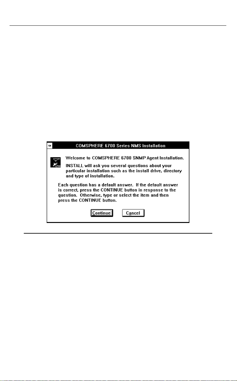
5. Choose OK. The Welcome window appears, as shown in
Figure 2-1.
Figure 2-1. Welcome Window
Issue 2 December 1996
2-5
Page 19
Installation
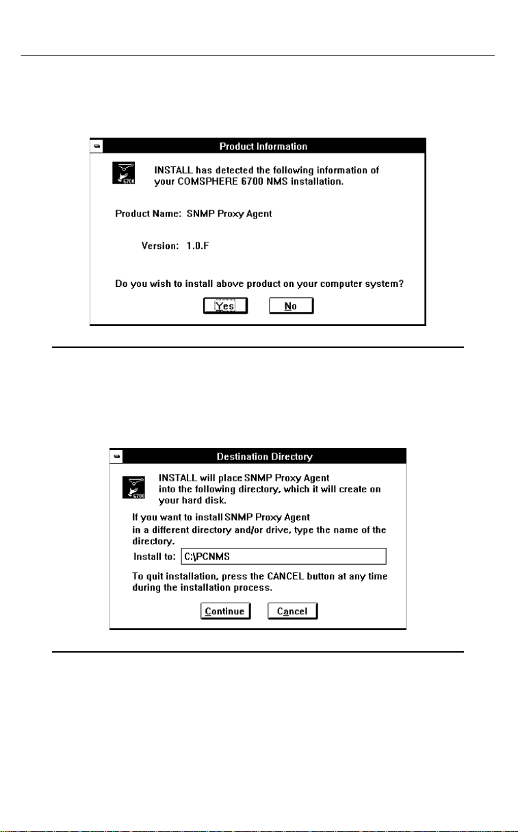
6. Choose Continue. The Product Information window
appears, as shown in Figure 2-2.
Figure 2-2. Product Information Window
7. Choose Yes. The Destination Directory window appears, as
shown in Figure 2-3.
Figure 2-3. Destination Directory Window
The Destination Directory window allows you to place the
NMS software into a specific directory. A single directory
within a single partition is required.
8. Enter a subdirectory location or choose the default setting
C:\PCNMS.
2-6 Issue 2 December 1996
Page 20
Installation
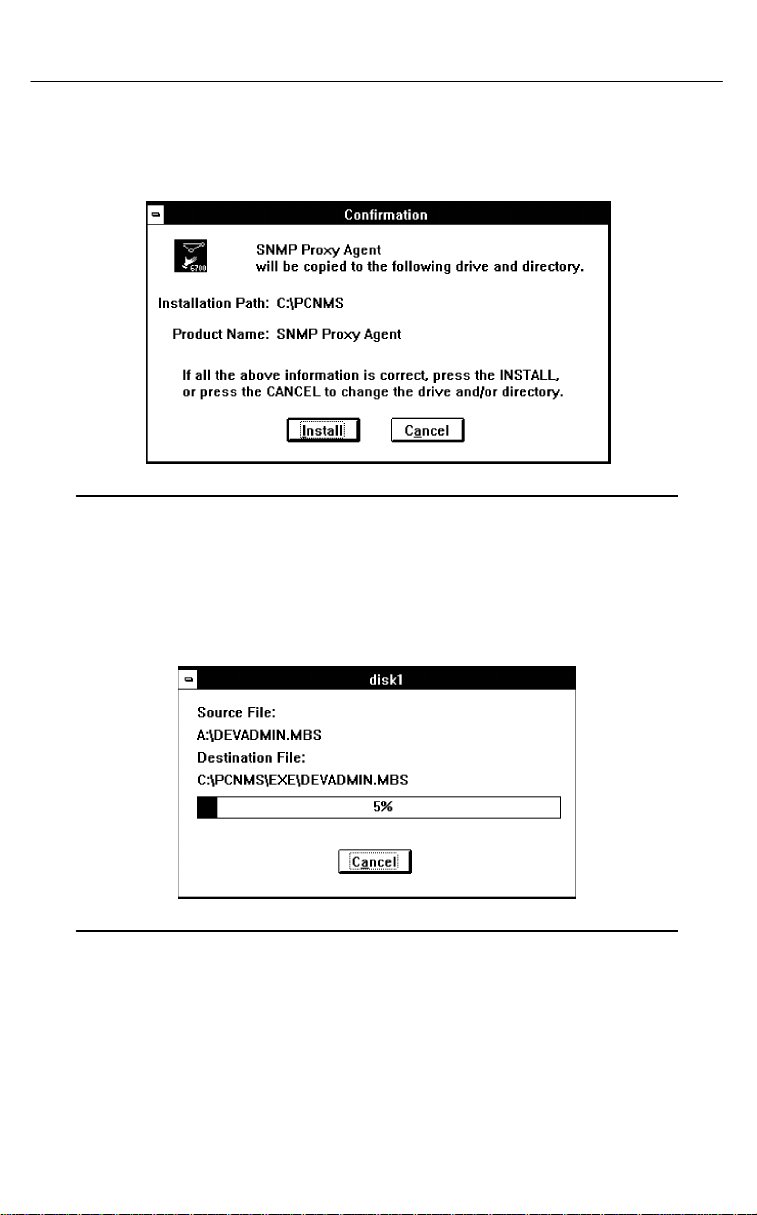
9. Choose Continue. The Confirmation window appears, as
shown in Figure 2-4.
Figure 2-4. Confirmation Window
10. Choose Install to confirm the installation of the NMS
software into the specified directory. The Completion status
window appears, as shown in Figure 2-5.
Figure 2-5. Completion Status Window
This window displays a bar indicating the percentage of
completion for the current installation. In addition, the names
of the files being installed appear above the bar until the
installation is complete. Then the Installation Completed!
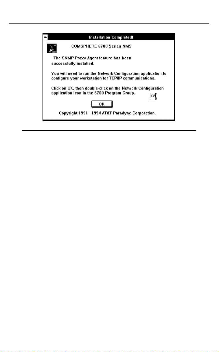
window appears, as shown in Figure 2-6.
Issue 2 December 1996
2-7
Page 21
Installation
Figure 2-6. Installation Completed! Window
11. Choose OK.
Configuring the SNMP Proxy
Agent Feature for TCP/IP
Networks
After installation, use the Network Configuration application to
customize your configuration for TCP/IP networks. For details on
doing so, refer to the
Management System Network Configuration Guide
COMSPHERE 6700 Series Network
.
2-8 Issue 2 December 1996
Page 22

Management Information Bases
3
MIB-II Support
The SNMP Proxy Agent feature includes support for the
standard Management Information Base (MIB-II) used with
network management protocols in TCP/IP-based internets. This
support is provided by the NEWT component. The following
MIB-II groups are supported as specified in RFC 1213.
System Group
Interface Group
Address Translation Table Group
IP Group
ICMP Group
TCP Group
UDP Group
Specific characteristics of the system and interface groups are
noted in the following paragraphs.
NOTE:
Because this product is a
information reflects the state of the TCP/IP interface in the
workstation where the proxy is running. If a MIB-II variable
is accessed for a proxied device, the MIB-II value for the
proxy workstation is returned.
proxy agent
Issue 2 December 1996
, the MIB-II
3-1
Page 23

Management Information Bases
Á
Á
Á
Á
Á
Á
MIB-II System Group Overview
The MIB-II system group contains system description
information. You may customize the sysContact, sysName, and
sysLocation text. For further details, refer to the
for Windows Installation and User’s Guide.
MIB browser output examples for the system group are
presented in Table 3-1.
Table 3-1. MIB Browser Output Table
Object
Descriptor
ÁÁÁÁ
Example
ББББББББББББ
NEWT TCP/IP
sysDescr
ÁÁÁÁ
sysObjectID
sysUpTime
sysContact
ÁÁÁÁ
sysName
sysLocation
sysServices
80486 DOS 6.20 Windows 3.10 Enhanced
Mode NetManage SNMP 4.00
ББББББББББББ
NetManage, Inc.
00:00:24.99
COMSPHERE 6700 NMS Administrator
ББББББББББББ
Paradyne COMSPHERE 6700
COMSPHERE 6700 NMS Workstation
76
MIB-II Interface Group Overview
The MIB-II interface group contains information about TCP/IP
interfaces configured within NEWT.
3-2 Issue 2 December 1996
Page 24

Management Information Bases
COMSPHERE 6700 Series
NMS Enterprise MIBs
Four new enterprise Management Information Base (MIB)
definitions are introduced with SNMP Proxy Agent Release 1.0:
COMSPHERE 6700 NMS MIB
COMSPHERE 6700 Device MIB
Front Panel MIB
Call Directory MIB
NOTE:
For additional installation information, refer to the
readme.txt file on the COMSPHERE 6700 SNMP MIBs
diskette, Part No. 869-2745-0011.
Figure 3-1 shows the Structure of Management Information
(SMI) defined object identifier prefix tree that includes the
COMSPHERE 6700 Enterprise MIBs.
Issue 2 December 1996
3-3
Page 25

Management Information Bases
Figure 3-1. SMI Defined Object Identifier Prefix Tree
The COMSPHERE 6700 NMS and Device MIBs are defined in
the appendices.
3-4 Issue 2 December 1996
Page 26

Management Information Bases
COMSPHERE 6700 NMS MIB
Overview
The NMS MIB administers the 6700 Series NMS. The following
groups are defined in the NMS MIB.
NMS Administration Group
NMS System Group
NMS Device Group
NMS Manager Group
NMS Test Group
Refer to Appendix A for a full description of the COMSPHERE
6700 NMS MIBs.
COMSPHERE 6700 Device MIB
Overview
The Device MIB supports management of COMSPHERE 3600,
3800, and 3900 model-type devices attached to a COMSPHERE
6700 Series NMS.
The device attributes and commands are defined in a
device-independent manner that supports both modems and
DSUs. The following groups are defined in the Device MIB.
Device Administration Group
Device Identity Group
Device Status Group
Device Circuit Quality Group
Device EIA Status Group
Device External Leads Group
Device Command Group
The SNMP Proxy Agent automatically provides a specific
community name for each managed device. An SNMP
management application must use the device specific
community name to select which device to act upon.
Refer to Appendix B for a full description of the COMSPHERE
6700 Device MIB.
Issue 2 December 1996
3-5
Page 27

Management Information Bases
Front Panel MIB Overview
The Front Panel MIB provides remote access to the front panel
of a device and is accessed using the community procedures
used for the 6700 Device MIB.
Front panel keypress codes can be sent to the device in Set
requests. The current front panel display can be retrieved with a
Get request to the front panel display table.
Refer to Appendix D for a full description of the Front Panel MIB.
Call Directory MIB Overview
The Call Directory MIB contains call directory data for a device
and is accessed using the community procedures used for the
6700 Device MIB. The number of entries in a device’s call
directory table is dependent on the device type.
Refer to Appendix D for a full description of the Call Directory
MIB.
DOS, Windows, and
Workstation MIBs
Additional MIBs supported by the SNMP Proxy Agent feature
include NetManage Enterprise MIBs for DOS, Windows, and
Workstations.
Support for these MIBs is provided by the NEWT software and
can be turned on/off through the COMSPHERE 6700 Series
NMS Network Configuration feature. To do so, refer to the
NEWT TCP/IP for Windows Installation and User’s Guide
3-6 Issue 2 December 1996
.
Page 28

Management Information Bases
SNMP Traps Overview
COMSPHERE 6700 NMS alerts may be exported to authorized
SNMP managers as SNMP traps. Traps are forwarded for any
event that makes it through the COMSPHERE 6700 Series
NMS’s alert filter.
All traps are enterprise specific, with an OBJECT IDENTIFIER
specifying the COMSPHERE 6700 Enterprise Device product.
Trap forwarding can be turned on/off for each SNMP manager in
the authorized manager list through the COMSPHERE 6700
Series NMS Network Configuration feature or via SNMP. To do
so, refer to the
Management System Network Configuration Guide
Refer to Appendix C for a full description of the COMSPHERE
6700 Enterprise Traps.
COMSPHERE 6700 Series Network
.
Device Traps
Device traps are generated for device-related alert conditions
detected by the COMSPHERE 6700 Series NMS.
The Enterprise OBJECT IDENTIFIER used in device traps is the
following:
iso(1) org(3) dod(6) internet(1) private(4) enterprises(1) att-2(74) att-products(1)
paradyneNMS-products(13) nms6700-products(2) devOid(2)
The community name used in device product traps is the Device
Read Community. This is formed by concatenating base read
community with the device name.
The following COMSPHERE 6700 Device MIB variable bindings
are included in each trap message.
Device Name (devAdminName)
Device Type (devAdminModelType)
System Time (nmsSystemTime)
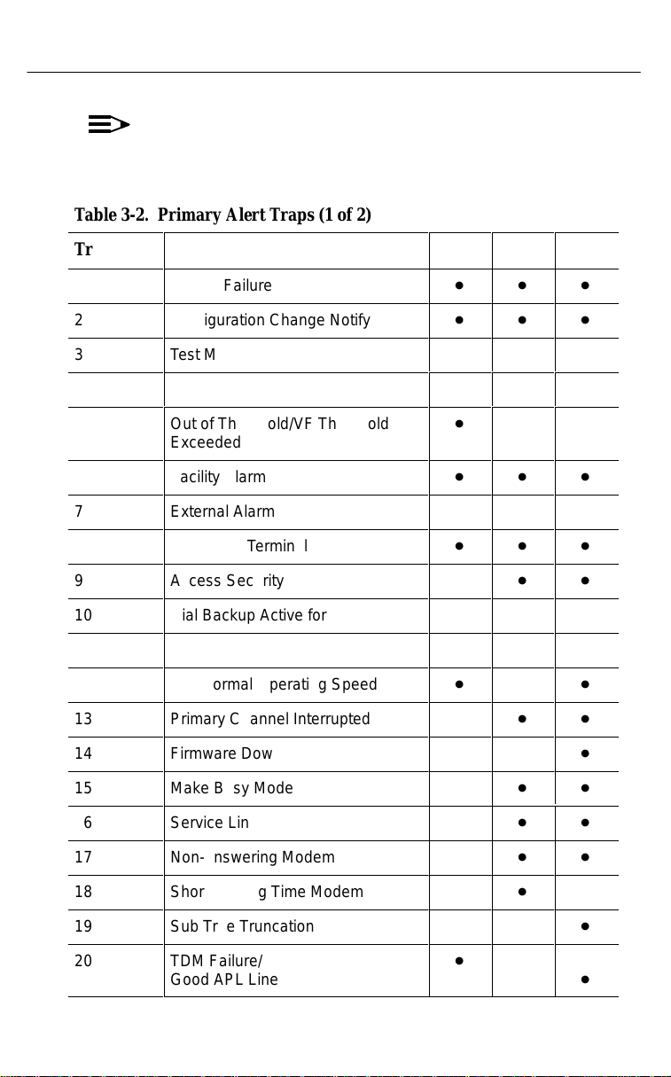
Table 3-2 identifies which primary alert traps apply to the specific
devices. Trap numbers 1–32 are reserved for primary alerts.
Issue 2 December 1996
3-7
Page 29
Management Information Bases
Á
Á
Á
Á
Á
Á
Á
Á
Á
Á
Á
Á
Á
Á
Á
Á
Á
Á
Á
Á
Á
Á
Á
Á
Á
Á
Á
Á
Á
Á
Á
Á
Á
Á
NOTE:
The state of a device’s primary alerts can also be read
from devStatusAlert.
Table 3-2. Primary Alert Traps (1 of 2)
БББББББББББББББББББ
Trap
ÁÁ
Primary Alert Traps
БББББББББ
3600
Á
3800
ÁÁ
3900
ÁÁ
1
2
3
ÁÁ
4
5
ÁÁ
6
7
8
ÁÁ
9
10
ÁÁ11БББББББББ
12
ÁÁ
13
14
15
ÁÁ
16
ÁÁ
Device Failure
Configuration Change Notify
Test Mode
БББББББББ
Disabled
Out of Threshold/VF Threshold
Exceeded
БББББББББ
Facility Alarm
External Alarm
Streaming Terminal
БББББББББ
Access Security
Dial Backup Active for APL
DTE Alarm
Sub-normal Operating Speed
БББББББББ
Primary Channel Interrupted
Firmware Downloading
Make Busy Mode
БББББББББ
Service Line
БББББББББ
D
D
D
Á
D
D
Á
D
D
D
Á
D
ÁDÁÁDÁÁ
D
Á
ÁÁÁÁDÁÁ
ÁÁÁÁDÁÁ
D
D
ÁÁDÁÁ
D
D
D
D
D
D
ÁÁDÁÁ
D
D
ÁÁDÁÁ
D
D
D
D
D
D
D
D
ÁÁDÁÁ
D
D
D
D
D
D
D
17
18
19
ÁÁ
20
ÁÁ
Non-answering Modem
Short Holding Time Modem
Sub Tree Truncation
БББББББББ
TDM Failure/
Good APL Line
БББББББББ
3-8 Issue 2 December 1996
D
Á
D
Á
D
D
ÁÁ
ÁÁ
D
D
D
ÁÁ
D
ÁÁ
Page 30
Management Information Bases
Á
Á
Á
Á
Á
Á
Á
Á
Á
Á
Á
Á
Á
Á
Á
Á
Á
Á
Á
Á
Á
Á
Á
Á
Á
Á
Á
Á
Á
Á
Á
Table 3-2. Primary Alert Traps (2 of 2)
Trap
21
22
ÁÁ
23
32
Primary Alert Traps
Tributary Timeout
Dial Tone
БББББББББ
Redundant Power Supply
No Response
3600
Á
3800
D
D
ÁÁ
D
D
D
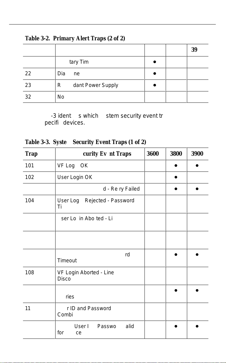
Table 3-3 identifies which system security event traps apply to
the specific devices.
Table 3-3. System Security Event Traps (1 of 2)
Trap
101
ÁÁ
102
103
104
ÁÁ
105
ÁÁ
System Security Event Traps
VF Login OK
БББББББББ
User Login OK
User Login Rejected - Retry Failed
User Login Rejected - Password
БББББББББ
Timeout
User Login Aborted - Line
БББББББББ
Disconnected
3600
ÁÁÁÁDÁÁ
3800
D
D
ÁÁÁÁDÁÁ
ÁÁÁÁDÁÁ
3900
ÁÁ
D
3900
D
D
D
D
D
106
ÁÁ
107
ÁÁ
108
ÁÁ
109
ÁÁ
110
ÁÁ
111
ÁÁ
VF Login Rejected - Password
БББББББББ
Invalid
VF Login Rejected - Password
БББББББББ
Timeout
VF Login Aborted - Line
БББББББББ
Disconnected
User Login OK - Multiple Password
Retries
БББББББББ
User ID and Password
Combination Invalid
БББББББББ
Invalid User ID - Password Valid
for Device
БББББББББ
Issue 2 December 1996
ÁÁÁÁDÁÁ
D
D
ÁÁÁÁDÁÁ
D
ÁÁÁÁDÁÁ
D
ÁÁÁÁDÁÁ
D
ÁÁÁÁDÁÁ
D
ÁÁÁÁDÁÁ
3-9
Page 31

Management Information Bases
Á
Á
Á
Á
Á
Á
Á
Á
Á
Á
Á
Á
Á
Á
Á
Á
Á
Á
Á
Á
Á
Á
Á
Á
Á
Á
Á
Á
Á
Á
Á
Á
Á
Á
Table 3-3. System Security Event Traps (2 of 2)
Trap
112
113
ÁÁ
114
ÁÁ
116
117
System Security Event Traps
Invalid Access Time
User Login Hack - Multiple
БББББББББ
Sequential Password Retries
Device Security Table Invalid
БББББББББ
Security Download Failed
Front Panel Modification
3600
ÁÁÁÁDÁÁ
ÁÁÁÁDÁÁ
Table 3-4 lists the Primary Alert Clear Notifications.
Table 3-4. Primary Alert Clear Notifications (1 of 2)
Trap
ÁÁ
201
202
ÁÁ
203
204
Primary Alert Traps
БББББББББ
Device Failure Cleared
Configuration Change Notify
Cleared
БББББББББ
Test Mode Cleared
Disabled Cleared
3600
Á
Á
ÁÁ
D
D
ÁÁDÁÁ
D
D
3800
D
D
D
3800
D
D
D
3900
D
D
D
D
D
3900
ÁÁ
D
D
D
D
205
ÁÁ
206
ÁÁ
207
208
209
210
ÁÁ
211
ÁÁ
212
ÁÁ
3-10 Issue 2 December 1996
Out of Threshold/VF Threshold
БББББББББ
Exceeded Cleared
Facility Alarm Cleared
БББББББББ
External Alarm Cleared
Streaming Terminal Cleared
Access Security Cleared
Dial Backup Active for APL
БББББББББ
Cleared
DTE Alarm Cleared
БББББББББ
Sub-normal Operating Speed
Cleared
БББББББББ
D
Á
D
Á
D
D
D
Á
D
Á
D
Á
ÁÁDÁÁ
ÁÁDÁÁ
D
D
D
ÁÁDÁÁ
ÁÁDÁÁ
D
D
D
D
D
D
D
D
ÁÁDÁÁ
Page 32

Management Information Bases
Á
Á
Á
Á
Á
Á
Á
Á
Á
Á
Á
Á
Á
Á
Á
Á
Á
Table 3-4. Primary Alert Clear Notifications (2 of 2)
Trap
213
ÁÁ
214
215
ÁÁ
216
217
218
ÁÁ
219
220
ÁÁ
221
ÁÁ
222
223
232
Primary Alert Traps
Primary Channel Interrupted
БББББББББ
Cleared
Firmware Downloading Cleared
Make Busy Mode Cleared
БББББББББ
Service Line Cleared
Non-answering Modem Cleared
Short Holding Time Modem
БББББББББ
Cleared
Sub Tree Truncation Cleared
TDM Failure Cleared/
БББББББББ
Good APL Line Cleared
Tributary Timeout Cleared
БББББББББ
Dial Tone Cleared
Redundant Power Supply Cleared
No Response Cleared
3600
3800
3900
D
ÁÁÁÁDÁÁ
D
ÁÁÁÁDÁÁ
D
D
D
D
D
D
D
ÁÁÁÁDÁÁ
D
D
Á
D
Á
ÁÁ
ÁÁ
D
ÁÁ
D
ÁÁ
D
D
D
D
D
SNMP Community Views
Different read and write community views are used for the
COMSPHERE 6700 NMS MIB and for each managed device
under the COMSPHERE 6700 Device MIB. Set up the
community names for community views using the COMSPHERE
6700 Series NMS Network Configuration feature. To do so, refer
COMSPHERE 6700 Series Network Management System
to the
Network Configuration Guide
.
Issue 2 December 1996
3-11
Page 33

Management Information Bases
The community names for the Device MIB are generated by
appending the desired device name to the appropriate base
name. Consider the following rules when creating community
names:
Community names should not be the prefix of a device
name.
Write community names can be used for both reads and
writes.
Call Directory MIB and Front Panel MIB both use the
same communities as the Device MIB.
Community Name Example
To better understand the use of community names, consider the
following example. Using community name settings as follows:
nmsAdminNmsReadCommunity = clear
nmsAdminNmsWriteCommunity = orange
nmsAdminBaseReadCommunity = teal
nmsAdminBaseWriteCommunity = pink
The community name for Get requests to the NMS MIB can be
either “clear” or “orange.” The community name for Set requests
to the NMS MIB must be “orange.”
The Device MIB community name for Get requests to a device
named “
“teal
requests to the device would be “pink
To access a Dial Backup Module (DBM) within a COMSPHERE
3600 Series DSU, the suffix “.dbm” is appended to the device
community name. For example, the DBM for a device named
DSU5
“
“pink
modem1
modem1
” would have a write community name of
DSU5.
” in the Device MIB would be either
” or “pink
modem1.
” The community name for Set
modem1.
dbm.”
”
3-12 Issue 2 December 1996
Page 34

MIB Definition
A
NMS6700-MIB DEFINITIONS ::= BEGIN
–– Title: COMSPHERE 6700 NMS MIB for Customer Network
Management
–– Copyright (C) 1996, Paradyne. All rights reserved.
––
–– This file may be freely copied and distributed as
–– long as no changes are made to it.
–– The NMS MIB contains attributes of the 6700 NMS entity.
–– The user can inspect and control the 6700 NMS via this MIB.
IMPORTS
IpAddress
FROM RFC1155-SMI
DisplayString
FROM RFC1213-MIB
OBJECT-TYPE
FROM RFC-1212
DateAndTime
FROM HOST-RESOURCES-MIB
nms-6700
FROM ATTP-ENTERPRISES;
––
–– Enterprise Identification for COMSPHERE 6700 NMS MIB
––
nms OBJECT IDENTIFIER ::= { nms-6700 1 }–– NMS MIB
Issue 2 December 1996
A-1
Page 35

MIB Definition
––
–– NMS MIB Groups
––
nmsAdmin OBJECT IDENTIFIER ::= { nms 1 }–– administration
nmsSystem OBJECT IDENTIFIER ::= { nms 2 }–– system identity
nmsDevice OBJECT IDENTIFIER ::= { nms 3 }–– 6700 devices
nmsManager OBJECT IDENTIFIER ::= { nms 4 }–– SNMP managers
nmsTest OBJECT IDENTIFIER ::= { nms 5 }–– T ests
A-2 Issue 2 December 1996
Page 36

MIB Definition
–– NMS Administration Group (nms 1)
–– NMS Information
nmsAdminName OBJECT -TYPE
SYNTAX DisplayString (SIZE (0..15))
ACCESS read-write
STATUS mandatory
DESCRIPTION
”Name of the 6700 NMS.”
::= { nmsAdmin 1 }
nmsAdminLocation OBJECT -TYPE
SYNTAX DisplayString (SIZE (0..40))
ACCESS read-write
STATUS mandatory
DESCRIPTION
”Location of the 6700 NMS.”
::= { nmsAdmin 2 }
nmsAdminContact1 OBJECT -TYPE
SYNTAX DisplayString (SIZE (0..40))
ACCESS read-write
STATUS mandatory
DESCRIPTION
”Contact 1 for the 6700 NMS.”
::= { nmsAdmin 3 }
nmsAdminContact2 OBJECT -TYPE
SYNTAX DisplayString (SIZE (0..40))
ACCESS read-write
STATUS mandatory
DESCRIPTION
”Contact 2 for the 6700 NMS.”
::= { nmsAdmin 4 }
–– NMS Community Names
nmsAdminNmsReadCommunity OBJECT -TYPE
SYNTAX DisplayString (SIZE (0..32))
ACCESS read-only
STATUS mandatory
DESCRIPTION
”NMS read community name. This community has read-only
Issue 2 December 1996
A-3
Page 37

MIB Definition
access to all objects in the COMSPHERE 6700 NMS MIB.
An exception applies with the nmsAdminNmsWriteCommunity
object for which the read community provides no access.”
::= { nmsAdmin 5 }
nmsAdminNmsWriteCommunity OBJECT-TYPE
SYNTAX DisplayString (SIZE (0..32))
ACCESS read-only
STATUS mandatory
DESCRIPTION
”NMS write community name. This community provides full
access to all objects in the COMSPHERE 6700 NMS MIB.”
::= { nmsAdmin 6 }
–– Device Community Names
nmsAdminBaseReadCommunity OBJECT -TYPE
SYNTAX DisplayString (SIZE (0..16))
ACCESS read-only
STATUS mandatory
DESCRIPTION
”Base read community name string used with Device MIB.
When string length is zero, the device read community
name is equal to the device name.”
::= { nmsAdmin 7 }
nmsAdminBaseWriteCommunity OBJECT-TYPE
SYNTAX DisplayString (SIZE (0..16))
ACCESS read-only
STATUS mandatory
DESCRIPTION
”Base write community name string used with Device MIB.
When string length is zero, the device write community
name is equal to the device name.”
::= { nmsAdmin 8 }
A-4 Issue 2 December 1996
Page 38

MIB Definition
–– NMS System Group (nms 2)
–– Time of Day
nmsSystemTime OBJECT-TYPE
SYNTAX DateAndTime
ACCESS read-only
STATUS mandatory
DESCRIPTION
”Specifies the date and time in RFC 1514 DateAndTime format.
The date and time are obtained from the system clock of
the workstation running the proxy agent software.”
::= { nmsSystem 1 }
–– Features
nmsSystemFeatures OBJECT -TYPE
SYNTAX INTEGER
ACCESS read-only
STATUS mandatory
DESCRIPTION
”Number of COMSPHERE 6700 NMS product or feature entries
in nmsSystemFeatureTable.”
::= { nmsSystem 2 }
nmsSystemFeatureTable OBJECT-TYPE
SYNTAX SEQUENCE OF NmsSystemFeatureEntry
ACCESS not-accessible
STATUS mandatory
DESCRIPTION
”The nms feature table contains a list of software
products/features installed in the COMSPHERE 6700 NMS.”
::= { nmsSystem 3 }
nmsSystemFeatureEntry OBJECT -TYPE
SYNTAX NmsSystemFeatureEntry
ACCESS not-accessible
STATUS mandatory
DESCRIPTION
”An entry in the software feature table.”
INDEX { nmsSystemFeatureIndex }
::= { nmsSystemFeatureT able 1 }
Issue 2 December 1996
A-5
Page 39

MIB Definition
–– Layout of one entry in nmsSystemFeatureT able.
NmsSystemFeatureEntry ::=
SEQUENCE {
nmsSystemFeatureIndex
INTEGER,
nmsSystemFeatureName
DisplayString,
nmsSystemFeatureVersion
DisplayString,
nmsSystemFeatureSerial
DisplayString
}
–– Index
nmsSystemFeatureIndex OBJECT -TYPE
SYNTAX INTEGER
ACCESS read-only
STATUS mandatory
DESCRIPTION
”The index of the entry.”
::= { nmsSystemFeatureEntry 1 }
–– Name
nmsSystemFeatureName OBJECT -TYPE
SYNTAX DisplayString (SIZE (0..25))
ACCESS read-only
STATUS mandatory
DESCRIPTION
”Name of system product or feature.”
::= { nmsSystemFeatureEntry 2 }
–– Version
nmsSystemFeatureVersion OBJECT-TYPE
SYNTAX DisplayString (SIZE (0..25))
ACCESS read-only
STATUS mandatory
DESCRIPTION
”Version of system product or feature.”
A-6 Issue 2 December 1996
Page 40

MIB Definition
::= { nmsSystemFeatureEntry 3 }
–– Serial Number
nmsSystemFeatureSerial OBJECT -TYPE
SYNTAX DisplayString (SIZE (0..25))
ACCESS read-only
STATUS mandatory
DESCRIPTION
”Serial number of system product or feature. If feature
has no serial number, this object contains a zero length
string.”
::= { nmsSystemFeatureEntry 4 }
Issue 2 December 1996
A-7
Page 41

MIB Definition
–– NMS Device Group (nms 3)
nmsDevices OBJECT -TYPE
SYNTAX INTEGER
ACCESS read-only
STATUS mandatory
DESCRIPTION
”The number of devices configured in the 6700 nms network.
This is also the number of entries in nmsDeviceT able.”
::= { nmsDevice 1 }
nmsDeviceT able OBJECT-TYPE
SYNTAX SEQUENCE OF NmsDeviceEntry
ACCESS not-accessible
STATUS mandatory
DESCRIPTION
”The nms device table contains an alpha-sorted list of names
of devices configured for management in the COMSPHERE 6700
NMS.”
::= { nmsDevice 2 }
nmsDeviceEntry OBJECT-TYPE
SYNTAX NmsDeviceEntry
ACCESS not-accessible
STATUS mandatory
DESCRIPTION
”An entry in the nms device table.”
INDEX { nmsDeviceIndex }
::= { nmsDeviceT able 1 }
–– Layout of one entry in nmsDeviceT able.
NmsDeviceEntry ::=
SEQUENCE {
nmsDeviceIndex
INTEGER,
nmsDeviceName
DisplayString
}
nmsDeviceIndex OBJECT -TYPE
SYNTAX INTEGER
ACCESS read-only
STATUS mandatory
DESCRIPTION
A-8 Issue 2 December 1996
Page 42

MIB Definition
”This object is the row index of the nmsDevice table.
Note that a device’s index in the table may change as
devices are added or removed from the 6700 nms network,
thus this index should not be used as a device ID.”
::= { nmsDeviceEntry 1 }
nmsDeviceName OBJECT -TYPE
SYNTAX DisplayString (SIZE (0..15))
ACCESS read-only
STATUS mandatory
DESCRIPTION
”This object is the device name, as assigned within the
COMSPHERE 6700 NMS.”
::= { nmsDeviceEntry 2 }
–– NMS Manager Group (nms 4)
–– Number of Authorized SNMP Managers
nmsManagers OBJECT -TYPE
SYNTAX INTEGER
ACCESS read-only
STATUS mandatory
DESCRIPTION
”This object contains the number of entries in
nmsManagerTable.”
::= { nmsManager 1 }
–– SNMP Manager T able
nmsManagerTable OBJECT-TYPE
SYNTAX SEQUENCE OF NmsManagerEntry
ACCESS not-accessible
STATUS mandatory
DESCRIPTION
”The manager table contains a list of SNMP managers
authorized access to the COMSPHERE 6700 MIBs.”
::= { nmsManager 2 }
nmsManagerEntry OBJECT -TYPE
SYNTAX NmsManagerEntry
ACCESS not-accessible
STATUS mandatory
Issue 2 December 1996
A-9
Page 43

MIB Definition
DESCRIPTION
”An entry in the manager table. Entries are indexed
by IP Address.”
INDEX { nmsManagerAddress }
::= { nmsManagerT able 1 }
–– Layout of one entry in nmsManagerT able.
NmsManagerEntry ::=
SEQUENCE {
nmsManagerAddress
IpAddress,
nmsManagerName
DisplayString,
nmsManagerAccess
INTEGER,
nmsManagerTraps
INTEGER,
nmsManagerLocation
DisplayString,
nmsManagerContact1
DisplayString,
nmsManagerContact2
DisplayString,
nmsManagerEntryStatus
INTEGER
}
–– Table Index (Manager IP Address)
nmsManagerAddress OBJECT -TYPE
SYNTAX IpAddress
ACCESS read-only
STATUS mandatory
DESCRIPTION
”This object is the row index in the manager table.”
::= { nmsManagerEntry 1 }
–– Manager Name
nmsManagerName OBJECT -TYPE
SYNTAX DisplayString (SIZE (1..16))
ACCESS read-write
A-10 Issue 2 December 1996
Page 44

MIB Definition
STATUS mandatory
DESCRIPTION
”This object is the NMS manager name. The manager name
must be unique in the table.
If a set operation is performed for a non-existing instance
(i.e., index is a new IP address), a new table entry for
the specified IP address will be created. The new entry’s
nmsManagerAccess will be defaulted to read-only(2), the
nmsManagerTraps to disabled(2), the nmsManagerLocation,
nmsManagerContact1, and nmsManagerContact2 to zero length
octet strings, and nmsManagerStatus to valid(1).”
::= { nmsManagerEntry 2 }
–– Access
nmsManagerAccess OBJECT -TYPE
SYNTAX INTEGER {
no-access(1),
read-only-access(2),
read-write-access(3)
}
ACCESS read-write
STATUS mandatory
DESCRIPTION
”Maximum manager access level setting can be none(1),
read-only(2), or read-write(3).”
::= { nmsManagerEntry 3 }
–– Traps
nmsManagerTraps OBJECT-TYPE
SYNTAX INTEGER {
enabled(1),
disabled(2)
}
ACCESS read-write
STATUS mandatory
DESCRIPTION
”Specifies if trap forwarding is enabled for this manager.”
::= { nmsManagerEntry 4 }
–– Location
Issue 2 December 1996
A-11
Page 45

MIB Definition
nmsManagerLocation OBJECT-TYPE
SYNTAX DisplayString (SIZE (0..40))
ACCESS read-write
STATUS mandatory
DESCRIPTION
”Text string describing manager location.”
::= { nmsManagerEntry 5 }
–– Contact1
nmsManagerContact1 OBJECT -TYPE
SYNTAX DisplayString (SIZE (0..40))
ACCESS read-write
STATUS mandatory
DESCRIPTION
”Text string describing manager contact 1.”
::= { nmsManagerEntry 6 }
–– Contact2
nmsManagerContact2 OBJECT -TYPE
SYNTAX DisplayString (SIZE (0..40))
ACCESS read-write
STATUS mandatory
DESCRIPTION
”Text string describing manager contact 2.”
::= { nmsManagerEntry 7 }
–– Entry Status (Used to Delete an Entry)
nmsManagerEntryStatus OBJECT -TYPE
SYNTAX INTEGER {
valid(1),
invalid(2) –– deletes entry from table
}
ACCESS read-write
STATUS mandatory
DESCRIPTION
”This object is used to delete an entry from the table.
Only the invalid(2) value is allowed on write.”
::= { nmsManagerEntry 8 }
A-12 Issue 2 December 1996
Page 46

MIB Definition
–– NMS T est Group (nms 5)
–– T extual Convention for Test Result Validity Indicator
TestResultValidity ::=
INTEGER {
valid-final(1),
valid-intermediate(2),
not-available-yet(3),
count-overflow(4),
not-used(5)
}
–– Number of T est Table Entries
nmsT estEntries OBJECT-TYPE
SYNTAX INTEGER
ACCESS read-only
STATUS mandatory
DESCRIPTION
”The number of NMS Test table entries that are configured.
This number is controlled by the following lines in
the 6700 profile (default value is shown).
[SNMP]
NmsTestEntries=8”
::= { nmsT est 1 }
–– T est Table
nmsT estTable OBJECT-TYPE
SYNTAX SEQUENCE OF NmsTestEntry
ACCESS not-accessible
STATUS mandatory
DESCRIPTION
”The NMS Test table uses RMON-style arbitration (RFC 1271)
to allocate device test slots. There are 8 (by default)
simultaneous test slots available.
Each test slot controls testing of a single device (or a
control-tributary pair, depending on the test type).”
::= { nmsT est 2 }
Issue 2 December 1996
A-13
Page 47

MIB Definition
nmsT estEntry OBJECT-TYPE
SYNTAX NmsTestEntry
ACCESS not-accessible
STATUS mandatory
DESCRIPTION
”An entry in the nms test table.”
INDEX { nmsTestIndex }
::= { nmsT estTable 1 }
A-14 Issue 2 December 1996
Page 48

MIB Definition
–– Layout of one entry in nmsT estTable.
NmsT estEntry ::=
SEQUENCE {
nmsTestIndex
INTEGER,
nmsTestDeviceName
DisplayString,
nmsTestType
INTEGER,
nmsTestDuration
INTEGER,
nmsTestPortNumber
INTEGER,
nmsTestRemoteName
DisplayString,
nmsTestStatus
INTEGER,
nmsTestLocalTotalSecondsValidity
TestResultValidity,
nmsTestLocalTotalSeconds
INTEGER,
nmsTestLocalErrorSecondsValidity
TestResultValidity,
nmsTestLocalErrorSeconds
INTEGER,
nmsTestLocalTotalBlocksValidity
TestResultValidity,
nmsTestLocalTotalBlocks
INTEGER,
nmsTestLocalErrorBlocksValidity
TestResultValidity,
nmsTestLocalErrorBlocks
INTEGER,
nmsTestRemoteTotalSecondsValidity
TestResultValidity,
nmsTestRemoteTotalSeconds
INTEGER,
nmsTestRemoteErrorSecondsValidity
TestResultValidity,
nmsTestRemoteErrorSeconds
INTEGER,
nmsTestRemoteTotalBlocksValidity
TestResultValidity,
Issue 2 December 1996
A-15
Page 49

MIB Definition
nmsTestRemoteTotalBlocks
INTEGER,
nmsTestRemoteErrorBlocksValidity
TestResultValidity,
nmsTestRemoteErrorBlocks
INTEGER,
nmsTestTimeOutsValidity
TestResultValidity,
nmsTestTimeOuts
INTEGER,
nmsTestOwner
DisplayString,
nmsTestEntryStatus
INTEGER
}
–– Index
nmsT estIndex OBJECT-TYPE
SYNTAX INTEGER
ACCESS read-only
STATUS mandatory
DESCRIPTION
”This object is the test table entry index.”
::= { nmsT estEntry 1 }
––
–– Device Name
––
nmsT estDeviceName OBJECT-TYPE
SYNTAX DisplayString (SIZE (0..15))
ACCESS read-write
STATUS mandatory
DESCRIPTION
”The name of the device to test.”
::= { nmsT estEntry 2 }
––
–– T est Type
––
nmsT estType OBJECT-TYPE
A-16 Issue 2 December 1996
Page 50

MIB Definition
SYNTAX INTEGER {
self-test(1),
local-loop(2),
rem-digital-loop(3),
loc-digital-loop(4),
dte-loop(5),
bert(6),
local-loop-bert(7),
rdl-bert(8),
digital-test(9),
end-to-end-test(10),
abort(11)
}
ACCESS read-write
STATUS mandatory
DESCRIPTION
”This object is the test type. Test type self-test(1)
performs an internal self-test of the device. Test type
local-loop(2) places the device into local loopback (for
modems, this is a CCITT V.54 Loop 3). Test type
rem-digital-loop(3) places the device in a remote digital
loopback (for modems, this is a CCITT V.54 Loop 2). Test
type loc-digital-loop(4) forces a local device to loopback
any data received from the remote device (this is useful if
the remote device is incapable of initiating a remote
digital loopback from its location). T est type dte-loop(5)
loops a DSU’s data port back to the DTE/DCE interface on a
per-port basis without affecting the operation of the
remaining ports. Test type bert(6) initiates a pattern
test. Test type local-loop-bert(7) places the device into
local loopback and initiates a pattern test. T est type
rdl-bert(8) places the device into remote digital loopback
and initiates a pattern test. Test type digital-test(9)
initiates a digital test of a pair of DSUs or DBMs and
the data circuit between them. Test type
end-to-end-test(10) initiates an end to end test of two
devices. T est type abort aborts the current test.”
::= { nmsT estEntry 3 }
––
–– Test Duration
––
nmsT estDuration OBJECT-TYPE
Issue 2 December 1996
A-17
Page 51

MIB Definition
SYNTAX INTEGER
ACCESS read-write
STATUS mandatory
DESCRIPTION
”T est duration in seconds (or blocks). Only applicable for
the following test types: bert, local-loop-bert, rdl-bert,
digital-test, end-to-end-test.”
::= { nmsT estEntry 4 }
––
–– Port Number
––
nmsT estPortNumber OBJECT-TYPE
SYNTAX INTEGER {
aggregate(1),
port1(2),
port2(3),
port3(4),
port4(5),
port5(6),
port6(7)
}
ACCESS read-write
STATUS mandatory
DESCRIPTION
”Port number. Only applicable for multi-port devices.
Also only applicable for the following test types:
rem-digital-loop, loc-digital-loop, dte-loop, bert,
local-loop-bert, rdl-bert, digital-test, end-to-end-test.”
::= { nmsT estEntry 5 }
––
–– Remote Device Name
––
nmsT estRemoteName OBJECT-TYPE
SYNTAX DisplayString (SIZE (0..15))
ACCESS read-write
STATUS mandatory
DESCRIPTION
”Remote device name. Only applicable for the following test
types: digital-test, end-to-end-test.”
A-18 Issue 2 December 1996
Page 52

MIB Definition
::= { nmsT estEntry 6 }
––
–– Test Status
––
nmsT estStatus OBJECT-TYPE
SYNTAX INTEGER {
idle(1),
testMode(2),
testRunning(3),
testAborted(4),
testFailed(5)
}
ACCESS read-only
STATUS mandatory
DESCRIPTION
”Test status.
Status of idle(1) indicates that the device is not in test
mode (from this control point); this is the initial value
after createRequest. Status of testMode(2) indicates that
the device is in a test mode (such as loopback); no further
test results are pending. Status of testRunning(3) means
the device is in test mode (such as bert test) and test
results are pending. Status of testAborted(4) indicates
that the device test was aborted and the device is no longer
in test mode. Status of testFailed(5) indicates that the
test has failed. Reason for test failure may be: invalid
test parameter; device locked by another user; conflict with
device environment, features, or configuration; device failure.”
::= { nmsT estEntry 7 }
–– Test Results
–– Local T otal Seconds
nmsT estLocalTotalSecondsValidity OBJECT-TYPE
SYNTAX TestResultValidity
ACCESS read-only
STATUS mandatory
DESCRIPTION
”Validity of the nmsTestLocalTotalSeconds test result object.”
::= { nmsT estEntry 8 }
Issue 2 December 1996
A-19
Page 53

MIB Definition
nmsT estLocalTotalSeconds OBJECT-TYPE
SYNTAX INTEGER
ACCESS read-only
STATUS mandatory
DESCRIPTION
”T otal seconds for local device. (For 3600 model type devices,
this variable is also called elapsed seconds.)”
::= { nmsT estEntry 9 }
–– Local Error Seconds
nmsT estLocalErrorSecondsValidity OBJECT-TYPE
SYNTAX TestResultValidity
ACCESS read-only
STATUS mandatory
DESCRIPTION
”Validity of the nmsTestLocalErrorSeconds test result object.”
::= { nmsT estEntry 10 }
nmsT estLocalErrorSeconds OBJECT-TYPE
SYNTAX INTEGER
ACCESS read-only
STATUS mandatory
DESCRIPTION
”Errored seconds elapsed for local device. (The value is not
used for 3600 model type devices.)”
::= { nmsT estEntry 11 }
–– Local T otal Blocks (Bits for 3600 DSU)
nmsT estLocalTotalBlocksValidity OBJECT-TYPE
SYNTAX TestResultValidity
ACCESS read-only
STATUS mandatory
DESCRIPTION
”Validity of the nmsTestLocalTotalBlocks test result object.”
::= { nmsT estEntry 12 }
nmsT estLocalTotalBlocks OBJECT-TYPE
SYNTAX INTEGER
ACCESS read-only
STATUS mandatory
DESCRIPTION
”Total blocks for local device.”
::= { nmsT estEntry 13 }
A-20 Issue 2 December 1996
Page 54

MIB Definition
–– Local Error Blocks (Bits for 3600 DSU)
nmsT estLocalErrorBlocksValidity OBJECT-TYPE
SYNTAX TestResultValidity
ACCESS read-only
STATUS mandatory
DESCRIPTION
”Validity of the nmsTestLocalErrorBlocks test result
object.”
::= { nmsT estEntry 14 }
nmsT estLocalErrorBlocks OBJECT-TYPE
SYNTAX INTEGER
ACCESS read-only
STATUS mandatory
DESCRIPTION
”Error Blocks for 3800 and 3900 modems, or Local Error
Blocks (actually Bits) for 3600 DSUs; ”
::= { nmsT estEntry 15 }
–– Remote T otal Seconds
nmsT estRemoteTotalSecondsV alidity OBJECT-TYPE
SYNTAX TestResultValidity
ACCESS read-only
STATUS mandatory
DESCRIPTION
”Validity of the nmsTestRemoteTotalSeconds test result object.”
::= { nmsT estEntry 16 }
nmsT estRemoteTotalSeconds OBJECT-TYPE
SYNTAX INTEGER
ACCESS read-only
STATUS mandatory
DESCRIPTION
”T otal seconds for remote device. (For 3600 model type
devices, this variable is also called elapsed seconds.)”
::= { nmsT estEntry 17 }
–– Remote Error Seconds
nmsT estRemoteErrorSecondsValidity OBJECT-TYPE
SYNTAX TestResultValidity
ACCESS read-only
STATUS mandatory
Issue 2 December 1996
A-21
Page 55

MIB Definition
DESCRIPTION
”Validity of the nmsTestRemoteErrorSeconds test result object.”
::= { nmsT estEntry 18 }
nmsT estRemoteErrorSeconds OBJECT-TYPE
SYNTAX INTEGER
ACCESS read-only
STATUS mandatory
DESCRIPTION
”Errored seconds elapsed for the remote device. (The value
is not used for 3600 model type devices.)”
::= { nmsT estEntry 19 }
–– Remote T otal Blocks (Bits for 3600 DSU)
nmsT estRemoteTotalBlocksV alidity OBJECT-TYPE
SYNTAX TestResultValidity
ACCESS read-only
STATUS mandatory
DESCRIPTION
”Validity of the nmsTestRemoteTotalBlocks test result object.”
::= { nmsT estEntry 20 }
nmsT estRemoteTotalBlocks OBJECT-TYPE
SYNTAX INTEGER
ACCESS read-only
STATUS mandatory
DESCRIPTION
”Total blocks for remote device.”
::= { nmsT estEntry 21 }
–– Remote Error Blocks (Bits for 3600 DSU)
nmsT estRemoteErrorBlocksValidity OBJECT-TYPE
SYNTAX TestResultValidity
ACCESS read-only
STATUS mandatory
DESCRIPTION
”Validity of the nmsTestRemoteErrorBlocks test result
object.”
::= { nmsT estEntry 22 }
nmsT estRemoteErrorBlocks OBJECT-TYPE
SYNTAX INTEGER
ACCESS read-only
A-22 Issue 2 December 1996
Page 56

MIB Definition
STATUS mandatory
DESCRIPTION
”Remote Error blocks (actually Bits). Not used for 3800 and
3900 model type devices.)”
::= { nmsT estEntry 23 }
–– Time Outs
nmsT estTimeOutsValidity OBJECT -TYPE
SYNTAX TestResultValidity
ACCESS read-only
STATUS mandatory
DESCRIPTION
”Validity of the nmsTestTimeOuts test result object.”
::= { nmsT estEntry 24 }
nmsT estTimeOuts OBJECT-TYPE
SYNTAX INTEGER
ACCESS read-only
STATUS mandatory
DESCRIPTION
”Time outs. Not used for 3800 and 3900 model type
devices.”
::= { nmsT estEntry 25 }
–– Test Owner
nmsT estOwner OBJECT-TYPE
SYNTAX DisplayString (SIZE (0..255))
ACCESS read-write
STATUS mandatory
DESCRIPTION
”The entity that configured this entry and is therefore
using the resources assigned to it.
It is suggested that this string contain one or more
of the following:
IP address, management station name, network manager’s
name, location, or phone number.”
::= { nmsT estEntry 26 }
Issue 2 December 1996
A-23
Page 57

MIB Definition
–– Entry Status
nmsT estEntryStatus OBJECT-TYPE
SYNTAX INTEGER {
valid(1),
createRequest(2),
underCreation(3),
invalid(4)
}
ACCESS read-write
STATUS mandatory
DESCRIPTION
”The status of this nmsTestTable entry.
Setting this object to the value invalid(4) has the
effect of invalidating the corresponding entry. If
there is a test active when the entry is invalidated,
the test will be aborted.
An existing instance of this object cannot be set to
createRequest(2). This object may only be set to
createRequest(2) when a new test instance is created.
Immediately after completing the create operation, the
proxy agent will set this object to underCreation(3).
Entries shall exist in the underCreation(3) state until
the management station is finished configuring the
entry and sets this object to valid(1) or aborts,
setting this object to invalid(4). If the proxy agent
determines that an entry has been in the underCreation(3)
state for an abnormally long time, it may decide that the
management station has crashed. If the proxy agent makes
this decision, it will set the object to invalid(4).”
::= { nmsT estEntry 27 }
END
A-24 Issue 2 December 1996
Page 58

Device Enterprise MIB
Definition
B
NMS6700-DEV-MIB DEFINITIONS ::= BEGIN
–– Title: COMSPHERE 6700 Device MIB for Customer Network
Management
––
–– Copyright (C) 1996, Paradyne. All rights reserved.
––
–– This file may be freely copied and distributed as
–– long as no changes are made to it.
–– The Device MIB contains the common device attributes.
–– There is an instance of the Device MIB for each device in
–– the 6700 network. Each device is identified by a unique
–– community string. SNMP Management applications must use
–– the community name to specify the device to access.
IMPORTS
TimeTicks
FROM RFC1155-SMI
DisplayString
FROM RFC1213-MIB
OBJECT-TYPE
FROM RFC-1212
nms-6700
FROM ATTP-ENTERPRISES;
UInteger32 ::=
INTEGER
Issue 2 December 1996
B-1
Page 59

Device Enterprise MIB Definition
––
–– Enterprise Identification for COMSPHERE 6700 Device MIB
––
dev OBJECT IDENTIFIER ::= { nms-6700 2 } –– Device MIB
–– Device MIB Groups
devAdmin OBJECT IDENTIFIER ::= { dev 1 } –– administration
devIdentity OBJECT IDENTIFIER ::= { dev 2 } –– device identity
devStatus OBJECT IDENTIFIER ::= { dev 3 } –– status
devCirQual OBJECT IDENTIFIER ::= { dev 4 } –– circuit quality
devEIAStatus OBJECT IDENTIFIER ::= { dev 5 } –– EIA status
devExtLeads OBJECT IDENTIFIER ::= { dev 6 } –– external leads
devCommand OBJECT IDENTIFIER ::= { dev 7 } –– command
B-2 Issue 2 December 1996
Page 60

Device Enterprise MIB Definition
–– Device Administration Group (dev 1)
devAdminName OBJECT -TYPE
SYNTAX DisplayString (SIZE (0..15))
ACCESS read-only
STATUS mandatory
DESCRIPTION
”Device name. This is the name used by the COMSPHERE 6700
NMS to identify the device.”
::= { devAdmin 1 }
devAdminAdpAddress OBJECT -TYPE
SYNTAX DisplayString (SIZE (0..15))
ACCESS read-only
STATUS mandatory
DESCRIPTION
”Address of device in the ADP network (the network used by
the COMSPHERE 6700 NMS to access the device).”
::= { devAdmin 2 }
devAdminModelType OBJECT-TYPE
SYNTAX INTEGER {
dial(1),
apl(2),
dsu(3),
dbm(4)
}
ACCESS read-only
STATUS mandatory
DESCRIPTION
”Device model type is dial(1) for COMSPHERE 3800 dial
modems, apl(2) for COMSPHERE 3900 leased line modems,
dsu(3) for COMSPHERE 3600 DSUs, and dbm(4) for
COMSPHERE
3600 Dial Backup Modules.”
::= { devAdmin 3 }
devAdminSite OBJECT-TYPE
SYNTAX DisplayString (SIZE (0..15))
ACCESS read-only
STATUS mandatory
DESCRIPTION
”Device site name used by COMSPHERE 6700 NMS.”
::= { devAdmin 4 }
Issue 2 December 1996
B-3
Page 61

Device Enterprise MIB Definition
devAdminCabinet OBJECT-TYPE
SYNTAX DisplayString (SIZE (0..15))
ACCESS read-only
STATUS mandatory
DESCRIPTION
”Device cabinet name used by COMSPHERE 6700 NMS.”
::= { devAdmin 5 }
devAdminCarrier OBJECT-TYPE
SYNTAX DisplayString (SIZE (0..15))
ACCESS read-only
STATUS mandatory
DESCRIPTION
”Device carrier name used by COMSPHERE 6700 NMS.”
::= { devAdmin 6 }
devAdminCarrierSlot OBJECT -TYPE
SYNTAX INTEGER
ACCESS read-only
STATUS mandatory
DESCRIPTION
”Device carrier slot number.”
::= { devAdmin 7 }
devAdminCircuitName OBJECT -TYPE
SYNTAX DisplayString (SIZE (0..25))
ACCESS read-only
STATUS mandatory
DESCRIPTION
”Device circuit name.”
::= { devAdmin 8 }
devAdminContact1 OBJECT -TYPE
SYNTAX DisplayString (SIZE (0..25))
ACCESS read-only
STATUS mandatory
DESCRIPTION
”Device contact string #1.”
::= { devAdmin 9 }
devAdminContact2 OBJECT -TYPE
SYNTAX DisplayString (SIZE (0..25))
ACCESS read-only
STATUS mandatory
DESCRIPTION
B-4 Issue 2 December 1996
Page 62

Device Enterprise MIB Definition
”Device contact string #2.”
::= { devAdmin 10 }
devAdminComment OBJECT -TYPE
SYNTAX DisplayString (SIZE (0..40))
ACCESS read-only
STATUS mandatory
DESCRIPTION
”Device comment string.”
::= { devAdmin 11 }
devAdminDbmOption OBJECT -TYPE
SYNTAX INTEGER {
dbm-installed(1),
dbm-not-installed(2)
}
ACCESS read-only
STATUS mandatory
DESCRIPTION
”A value of dbm-installed(1) indicates that a dial backup
module option is installed.”
::= { devAdmin 12 }
devAdminMsdOption OBJECT -TYPE
SYNTAX INTEGER {
msd-installed(1),
msd-not-installed(2)
}
ACCESS read-only
STATUS mandatory
DESCRIPTION
”A value of msd-installed(1) indicates that a modem sharing
device option is installed.”
::= { devAdmin 13 }
devAdminMcmpOption OBJECT -TYPE
SYNTAX INTEGER {
mcmp-installed(1),
mcmp-not-installed(2)
}
ACCESS read-only
STATUS mandatory
DESCRIPTION
”A value of mcmp-installed(1) indicates that a multi control
Issue 2 December 1996
B-5
Page 63

Device Enterprise MIB Definition
multi point option is installed.”
::= { devAdmin 14 }
devAdminTdmOption OBJECT -TYPE
SYNTAX INTEGER {
tdm-installed(1),
tdm-not-installed(2)
}
ACCESS read-only
STATUS mandatory
DESCRIPTION
”A value of tdm-installed(1) indicates that a time division
multiplexer option is installed.”
::= { devAdmin 15 }
B-6 Issue 2 December 1996
Page 64

Device Enterprise MIB Definition
–– Device Identity Group (dev 2)
devIdentityModel OBJECT -TYPE
SYNTAX DisplayString (SIZE (0..40))
ACCESS read-only
STATUS mandatory
DESCRIPTION
”Model number.”
::= { devIdentity 1 }
devIdentityLineSpeed OBJECT -TYPE
SYNTAX DisplayString (SIZE (0..40))
ACCESS read-only
STATUS mandatory
DESCRIPTION
”Line speed.”
::= { devIdentity 2 }
devIdentitySoftwareVersion OBJECT-TYPE
SYNTAX DisplayString (SIZE (0..40))
ACCESS read-only
STATUS mandatory
DESCRIPTION
”Software version.”
::= { devIdentity 3 }
devIdentitySerialNumber OBJECT -TYPE
SYNTAX DisplayString (SIZE (0..40))
ACCESS read-only
STATUS mandatory
DESCRIPTION
”Serial number.”
::= { devIdentity 4 }
devIdentityApplModuleID OBJECT -TYPE
SYNTAX DisplayString (SIZE (0..40))
ACCESS read-only
STATUS mandatory
DESCRIPTION
”APPL module (if applicable, otherwise length is zero).”
::= { devIdentity 5 }
devIdentityAccessModuleID OBJECT -TYPE
SYNTAX DisplayString (SIZE (0..40))
ACCESS read-only
Issue 2 December 1996
B-7
Page 65

Device Enterprise MIB Definition
STATUS mandatory
DESCRIPTION
”Access module (if applicable, otherwise length is zero).”
::= { devIdentity 6 }
devIdentityRestoralOption OBJECT -TYPE
SYNTAX DisplayString (SIZE (0..40))
ACCESS read-only
STATUS mandatory
DESCRIPTION
”Restoral option (if applicable, otherwise length is zero).”
::= { devIdentity 7 }
devIdentityConfiguration OBJECT -TYPE
SYNTAX DisplayString (SIZE (0..40))
ACCESS read-only
STATUS mandatory
DESCRIPTION
”Configuration (if applicable, otherwise length is zero).”
::= { devIdentity 8 }
devIdentityInternationalStrap OBJECT -TYPE
SYNTAX DisplayString (SIZE (0..40))
ACCESS read-only
STATUS mandatory
DESCRIPTION
”International strap.”
::= { devIdentity 9 }
devIdentityHwPartNumber OBJECT -TYPE
SYNTAX DisplayString (SIZE (0..40))
ACCESS read-only
STATUS mandatory
DESCRIPTION
”Hardware part number.”
::= { devIdentity 10 }
devIdentitySwPartNumber OBJECT -TYPE
SYNTAX DisplayString (SIZE (0..40))
ACCESS read-only
STATUS mandatory
DESCRIPTION
”Software part number.”
::= { devIdentity 11 }
B-8 Issue 2 December 1996
Page 66

Device Enterprise MIB Definition
devIdentityOption1 OBJECT-TYPE
SYNTAX DisplayString (SIZE (0..40))
ACCESS read-only
STATUS mandatory
DESCRIPTION
”Option 1 (if applicable, otherwise length is zero).”
::= { devIdentity 12 }
devIdentityOption2 OBJECT -TYPE
SYNTAX DisplayString (SIZE (0..40))
ACCESS read-only
STATUS mandatory
DESCRIPTION
”Option 2 (if applicable, otherwise length is zero).”
::= { devIdentity 13 }
devIdentityOption3 OBJECT -TYPE
SYNTAX DisplayString (SIZE (0..40))
ACCESS read-only
STATUS mandatory
DESCRIPTION
”Option 3 (if applicable, otherwise length is zero).”
::= { devIdentity 14 }
devIdentityOption4 OBJECT -TYPE
SYNTAX DisplayString (SIZE (0..40))
ACCESS read-only
STATUS mandatory
DESCRIPTION
”Option 4 (if applicable, otherwise length is zero).”
::= { devIdentity 15 }
devIdentityOption5 OBJECT -TYPE
SYNTAX DisplayString (SIZE (0..40))
ACCESS read-only
STATUS mandatory
DESCRIPTION
”Option 5 (if applicable, otherwise length is zero).”
::= { devIdentity 16 }
devIdentityOption6 OBJECT -TYPE
SYNTAX DisplayString (SIZE (0..40))
ACCESS read-only
STATUS mandatory
DESCRIPTION
Issue 2 December 1996
B-9
Page 67

Device Enterprise MIB Definition
”Option 6 (if applicable, otherwise length is zero).”
::= { devIdentity 17 }
B-10 Issue 2 December 1996
Page 68

Device Enterprise MIB Definition
–– Device Status Group (dev 3)
devStatusConnectedDevice OBJECT -TYPE
SYNTAX DisplayString (SIZE (0..15))
ACCESS read-only
STATUS mandatory
DESCRIPTION
”The device name of the connected device. A zero length
string will be returned if the information is unavailable.”
::= { devStatus 1 }
devStatusConnectTime OBJECT-TYPE
SYNTAX TimeTicks
ACCESS read-only
STATUS mandatory
DESCRIPTION
”Connect time (in seconds).”
::= { devStatus 2 }
devStatusAlert OBJECT-TYPE
SYNTAX UInteger32
ACCESS read-only
STATUS mandatory
DESCRIPTION
”The current alerts for the device. The bit position number
starting with 0 and counting from the right (low order) bit
will indicate each active Primary Alert. The Primary Alerts
and their bit positions are defined as follows:
device-fail(0),
config-change-notify(1),
test-mode(2),
disabled(3),
out-of-threshold(4),
facility-alarm(5),
external-alarm(6),
streaming-terminal(7),
access-security(8),
dial-backup-active(9),
dte-alarm(10),
subnormal-speed(11),
primary-channel-interrupt(12),
firmware-downloading(13),
make-busy-mode(14),
Issue 2 December 1996
B-11
Page 69

Device Enterprise MIB Definition
service-line(15),
non-answering-modem(16),
short-holding-time-modem(17),
sub-tree-truncation(18),
tdm-failure-good-apl(19),
trib-timeout(20),
dial-tone(21),
redundant-power(22),
no-response(31)”
::= { devStatus 3 }
devStatusAlertDesc OBJECT -TYPE
SYNTAX DisplayString (SIZE (0..255))
ACCESS read-only
STATUS mandatory
DESCRIPTION
”Contains current Primary Alerts for the device, in text
format, delimited by semicolons (;). The following
abbreviations are used for the primary alerts:
Fail, CfgChng, Test, Disab, Thresh, FacAlrm, ExtAlrm,
StrTerm, AccSec, DialBkUp, DteAlrm, SubSpeed, PriChIr,
FwDnLd, MkBusy, Service, NoAns, ShrtHld, SubTrunc,
TdmFail(GoodApl), TribTO, DTone, Power, NoResp”
::= { devStatus 4 }
devStatusState OBJECT -TYPE
SYNTAX INTEGER {
idle-or-leased(1),
ring-indicate(2),
answering(3),
talk-mode(4),
off-hook(5),
dialing(6),
remote-ringing(7),
on-line(8),
dial-backup(9),
dial-standby(10)
}
ACCESS read-only
STATUS mandatory
DESCRIPTION
”The current state of the device.”
::= { devStatus 5 }
B-12 Issue 2 December 1996
Page 70

Device Enterprise MIB Definition
devStatusSpeed OBJECT-TYPE
SYNTAX INTEGER
ACCESS read-only
STATUS mandatory
DESCRIPTION
”The current data rate of the device, in bits per second.
A value of zero indicates that the device is training.”
::= { devStatus 6 }
devStatusCtrlTrib OBJECT-TYPE
SYNTAX INTEGER {
local-control(1),
remote-control(2),
tributary(3),
other(4)
}
ACCESS read-only
STATUS mandatory
DESCRIPTION
”Indicates the position of the device in the network.”
::= { devStatus 7 }
devStatusConfigType OBJECT-TYPE
SYNTAX INTEGER {
leased(1),
dial(2)
}
ACCESS read-only
STATUS mandatory
DESCRIPTION
”Indicates the configured mode of the device.”
::= { devStatus 8 }
devStatusPollingState OBJECT -TYPE
SYNTAX INTEGER {
active(1),
inactive(2),
inventory(3),
suspended(4)
}
ACCESS read-only
STATUS mandatory
DESCRIPTION
Issue 2 December 1996
B-13
Page 71

Device Enterprise MIB Definition
”Indicates the polling state of the device in the network.”
::= { devStatus 9 }
B-14 Issue 2 December 1996
Page 72

Device Enterprise MIB Definition
–– Circuit Quality Group (dev 4)
–– T ype Definition for Circuit Quality Validity indicators
–– Validity is not-used(6) if not supported by device type.
CirQualValidity ::=
INTEGER {
valid(1),
valid-greater-than(2),
valid-less-than(3),
not-valid-for-modulation-mode(4),
not-valid-for-multipoint-mode(5),
not-available-yet(6),
count-overflow(7),
not-used(8)
}
–– Bit Error Rate
devCirQualBitErrorRateValidity OBJECT-TYPE
SYNTAX CirQualValidity
ACCESS read-only
STATUS mandatory
DESCRIPTION
”Validity of the devCirQualBitErrorRate object.”
::= { devCirQual 1 }
devCirQualBitErrorRate OBJECT -TYPE
SYNTAX INTEGER
ACCESS read-only
STATUS mandatory
DESCRIPTION
”Bit error rate. Expressed as errors per billion (1E9)
bits.”
::= { devCirQual 2 }
–– Mean Squared Error
devCirQualMeanSquareErrorValidity OBJECT-TYPE
SYNTAX CirQualValidity
ACCESS read-only
STATUS mandatory
DESCRIPTION
Issue 2 December 1996
B-15
Page 73

Device Enterprise MIB Definition
”Validity of the devCirQualMeanSquareError object.”
::= { devCirQual 3 }
devCirQualMeanSquareError OBJECT -TYPE
SYNTAX INTEGER
ACCESS read-only
STATUS mandatory
DESCRIPTION
”Mean squared error.”
::= { devCirQual 4 }
–– Receive Level
devCirQualReceiveLevelValidity OBJECT-TYPE
SYNTAX CirQualValidity
ACCESS read-only
STATUS mandatory
DESCRIPTION
”Validity of the devCirQualReceiveLevel object.”
::= { devCirQual 5 }
devCirQualReceiveLevel OBJECT -TYPE
SYNTAX INTEGER
ACCESS read-only
STATUS mandatory
DESCRIPTION
”Receive level. Units are (dBm *10). Possible range is
–204.7 to +204.7 dBm.”
::= { devCirQual 6 }
–– 1004 Hz Loss
devCirQualHzLoss1004Validity OBJECT-TYPE
SYNTAX CirQualValidity
ACCESS read-only
STATUS mandatory
DESCRIPTION
”Validity of the devCirQualHzLoss1004 object.”
::= { devCirQual 7 }
devCirQualHzLoss1004 OBJECT -TYPE
SYNTAX INTEGER
ACCESS read-only
B-16 Issue 2 December 1996
Page 74

Device Enterprise MIB Definition
STATUS mandatory
DESCRIPTION
”1004 Hz loss.”
::= { devCirQual 8 }
–– Signal to Noise Ratio
devCirQualSignalToNoiseValidity OBJECT-TYPE
SYNTAX CirQualValidity
ACCESS read-only
STATUS mandatory
DESCRIPTION
”Validity of the devCirQualSignalToNoise object.”
::= { devCirQual 9 }
devCirQualSignalT oNoise OBJECT-TYPE
SYNTAX INTEGER
ACCESS read-only
STATUS mandatory
DESCRIPTION
”Signal to noise ratio. Units are (dB * 10). Possible
range is 0.0 to 102.3 dB.”
::= { devCirQual 10 }
–– Phase Jitter 0–20 Hz
devCirQualPhaseJitter20Validity OBJECT-TYPE
SYNTAX CirQualValidity
ACCESS read-only
STATUS mandatory
DESCRIPTION
”Validity of the devCirQualPhaseJitter20 object.”
::= { devCirQual 11 }
devCirQualPhaseJitter20 OBJECT -TYPE
SYNTAX INTEGER
ACCESS read-only
STATUS mandatory
DESCRIPTION
”Phase jitter 0–20 Hz. Units are (degrees * 10). Possible
range 0.0 to 33 degrees.”
::= { devCirQual 12 }
Issue 2 December 1996
B-17
Page 75

Device Enterprise MIB Definition
–– Phase Jitter 20–300 Hz
devCirQualPhaseJitter300Validity OBJECT-TYPE
SYNTAX CirQualValidity
ACCESS read-only
STATUS mandatory
DESCRIPTION
”Validity of the devCirQualPhaseJitter300 object.”
::= { devCirQual 13 }
devCirQualPhaseJitter300 OBJECT -TYPE
SYNTAX INTEGER
ACCESS read-only
STATUS mandatory
DESCRIPTION
”Phase jitter 20–300 Hz. Units are (degrees * 10).
Possible range 0.0 to 33 degrees.”
::= { devCirQual 14 }
–– Positive Attenuation
devCirQualPositiveAttenuationValidity OBJECT-TYPE
SYNTAX CirQualValidity
ACCESS read-only
STATUS mandatory
DESCRIPTION
”Validity of the devCirQualPositiveAttenuation
object.”
::= { devCirQual 15 }
devCirQualPositiveAttenuation OBJECT -TYPE
SYNTAX INTEGER
ACCESS read-only
STATUS mandatory
DESCRIPTION
”Positive attenuation.”
::= { devCirQual 16 }
–– Negative Attenuation
devCirQualNegativeAttenuationValidity OBJECT-TYPE
SYNTAX CirQualValidity
ACCESS read-only
B-18 Issue 2 December 1996
Page 76

Device Enterprise MIB Definition
STATUS mandatory
DESCRIPTION
”Validity of the devCirQualNegativeAttenuation
object.”
::= { devCirQual 17 }
devCirQualNegativeAttenuation OBJECT -TYPE
SYNTAX INTEGER
ACCESS read-only
STATUS mandatory
DESCRIPTION
”Negative attenuation.”
::= { devCirQual 18 }
–– Envelope Delay
devCirQualEnvelopeDelayValidity OBJECT-TYPE
SYNTAX CirQualValidity
ACCESS read-only
STATUS mandatory
DESCRIPTION
”Validity of the devCirQualEnvelopeDelay object.”
::= { devCirQual 19 }
devCirQualEnvelopeDelay OBJECT -TYPE
SYNTAX INTEGER
ACCESS read-only
STATUS mandatory
DESCRIPTION
”Envelope delay.”
::= { devCirQual 20 }
–– Frequency Offset
devCirQualFrequencyOffsetValidity OBJECT-TYPE
SYNTAX CirQualValidity
ACCESS read-only
STATUS mandatory
DESCRIPTION
”Validity of the devCirQualFrequencyOffset object.”
::= { devCirQual 21 }
devCirQualFrequencyOffset OBJECT-TYPE
Issue 2 December 1996
B-19
Page 77

Device Enterprise MIB Definition
SYNTAX INTEGER
ACCESS read-only
STATUS mandatory
DESCRIPTION
”Frequency offset. Units are (Hz * 10). Possible range
–51.1 to +51.1 Hz.”
::= { devCirQual 22 }
–– Non Linear Distortion
devCirQualNonLinearDistortionValidity OBJECT-TYPE
SYNTAX CirQualValidity
ACCESS read-only
STATUS mandatory
DESCRIPTION
”Validity of the devCirQualNonLinearDistortion
object.”
::= { devCirQual 23 }
devCirQualNonLinearDistortion OBJECT -TYPE
SYNTAX INTEGER
ACCESS read-only
STATUS mandatory
DESCRIPTION
”Non-linear distortion. Units are negative tenths of dB.
Possible range –0.0 to –102.3 dB. Example: –20 dB is
encoded as integer –200.”
::= { devCirQual 24 }
–– Retrains
devCirQualRetrainsValidity OBJECT-TYPE
SYNTAX CirQualValidity
ACCESS read-only
STATUS mandatory
DESCRIPTION
”Validity of the devCirQualRetrains object.”
::= { devCirQual 25 }
devCirQualRetrains OBJECT -TYPE
SYNTAX INTEGER
ACCESS read-only
STATUS mandatory
B-20 Issue 2 December 1996
Page 78

Device Enterprise MIB Definition
DESCRIPTION
”Retrains. Integer value represents the number of retrain
events during the last 15 minutes. Possible range is 0 to
4095.”
::= { devCirQual 26 }
–– Blown Startups
devCirQualBlownStartupsValidity OBJECT-TYPE
SYNTAX CirQualValidity
ACCESS read-only
STATUS mandatory
DESCRIPTION
”Validity of the devCirQualBlownStartups object.”
::= { devCirQual 27 }
devCirQualBlownStartups OBJECT -TYPE
SYNTAX INTEGER
ACCESS read-only
STATUS mandatory
DESCRIPTION
”Blown startups.”
::= { devCirQual 28 }
–– Gain Hits
devCirQualGainHitsValidity OBJECT-TYPE
SYNTAX CirQualValidity
ACCESS read-only
STATUS mandatory
DESCRIPTION
”Validity of the devCirQualGainHits object.”
::= { devCirQual 29 }
devCirQualGainHits OBJECT -TYPE
SYNTAX INTEGER
ACCESS read-only
STATUS mandatory
DESCRIPTION
”Gain hits. Integer value represents the number of gain hit
events during last 15 minutes. Possible range: 0 to 4095.”
::= { devCirQual 30 }
Issue 2 December 1996
B-21
Page 79

Device Enterprise MIB Definition
–– Phase Hits
devCirQualPhaseHitsValidity OBJECT-TYPE
SYNTAX CirQualValidity
ACCESS read-only
STATUS mandatory
DESCRIPTION
”Validity of the devCirQualPhaseHits object.”
::= { devCirQual 31 }
devCirQualPhaseHits OBJECT -TYPE
SYNTAX INTEGER
ACCESS read-only
STATUS mandatory
DESCRIPTION
”Phase hits. Integer value represents the number of phase
hit events during the last 15 minutes. Possible range is 0
to 4095.”
::= { devCirQual 32 }
–– Impulse Noise
devCirQualImpulseNoiseValidity OBJECT-TYPE
SYNTAX CirQualValidity
ACCESS read-only
STATUS mandatory
DESCRIPTION
”Validity of the devCirQualImpulseNoise object.”
::= { devCirQual 33 }
devCirQualImpulseNoise OBJECT -TYPE
SYNTAX INTEGER
ACCESS read-only
STATUS mandatory
DESCRIPTION
”Impulse noise. Integer value represents the number of
impulse noise events during the last 15 minutes. Possible
range is 0 to 4095.”
::= { devCirQual 34 }
–– Dropouts
devCirQualDropoutsValidity OBJECT-TYPE
SYNTAX CirQualValidity
B-22 Issue 2 December 1996
Page 80

Device Enterprise MIB Definition
ACCESS read-only
STATUS mandatory
DESCRIPTION
”Validity of the devCirQualDropouts object.”
::= { devCirQual 35 }
devCirQualDropouts OBJECT -TYPE
SYNTAX INTEGER
ACCESS read-only
STATUS mandatory
DESCRIPTION
”Dropouts. Integer value represents the number of dropout
events during the last 15 minutes. Possible range is 0 to
4095.”
::= { devCirQual 36 }
–– Line Quality
devCirQualLineQualityValidity OBJECT-TYPE
SYNTAX CirQualValidity
ACCESS read-only
STATUS mandatory
DESCRIPTION
”Validity of the devCirQualLineQuality object.”
::= { devCirQual 37 }
devCirQualLineQuality OBJECT -TYPE
SYNTAX INTEGER {
excellent(1),
good(2),
fair(3),
poor(4),
no-signal(5)
}
ACCESS read-only
STATUS mandatory
DESCRIPTION
”Line (signal) quality.”
::= { devCirQual 38 }
–– Near End Echo
devCirQualNearEndEchoValidity OBJECT-TYPE
Issue 2 December 1996
B-23
Page 81

Device Enterprise MIB Definition
SYNTAX CirQualValidity
ACCESS read-only
STATUS mandatory
DESCRIPTION
”Validity of the devCirQualNearEndEcho object.”
::= { devCirQual 39 }
devCirQualNearEndEcho OBJECT -TYPE
SYNTAX INTEGER
ACCESS read-only
STATUS mandatory
DESCRIPTION
”Near end echo. Units are (dB *10). Possible range
0.0 to –102.4 dB.”
::= { devCirQual 40 }
–– Far End Echo
devCirQualFarEndEchoValidity OBJECT-TYPE
SYNTAX CirQualValidity
ACCESS read-only
STATUS mandatory
DESCRIPTION
”Validity of the devCirQualFarEndEcho object.”
::= { devCirQual 41 }
devCirQualFarEndEcho OBJECT -TYPE
SYNTAX INTEGER
ACCESS read-only
STATUS mandatory
DESCRIPTION
”Far end echo. Units are (dB * 10). Possible range
0.0 to –102.4 dB.”
::= { devCirQual 42 }
–– Far End Delay
devCirQualFarEndDelayValidity OBJECT-TYPE
SYNTAX CirQualValidity
ACCESS read-only
STATUS mandatory
DESCRIPTION
”Validity of the devCirQualFarEndDelay object.”
B-24 Issue 2 December 1996
Page 82

Device Enterprise MIB Definition
::= { devCirQual 43 }
devCirQualFarEndDelay OBJECT -TYPE
SYNTAX INTEGER
ACCESS read-only
STATUS mandatory
DESCRIPTION
”Far end delay. Units are in milliseconds. Possible range
0 to 4095 ms.”
::= { devCirQual 44 }
–– Echo Frequency Offset
devCirQualEchoFreqOffsetValidity OBJECT-TYPE
SYNTAX CirQualValidity
ACCESS read-only
STATUS mandatory
DESCRIPTION
”Validity of the devCirQualEchoFreqOffset object.”
::= { devCirQual 45 }
devCirQualEchoFreqOffset OBJECT-TYPE
SYNTAX INTEGER
ACCESS read-only
STATUS mandatory
DESCRIPTION
”Echo frequency offset. Units are tenths of Hertz.
Possible range –51.1 to 51.1 Hz.”
::= { devCirQual 46 }
Issue 2 December 1996
B-25
Page 83

Device Enterprise MIB Definition
–– EIA Status Group (dev 5)
–– T extual Convention for EIA Status Integer
EIAStatus ::=
INTEGER {
off(1),
on(2),
unsupported-lead(3),
lead-changing(4)
}
–– Number of Ports (Number of Entries in EIA Status T able)
devEIAStatusPorts OBJECT-TYPE
SYNTAX INTEGER
ACCESS read-only
STATUS mandatory
DESCRIPTION
”Number of ports present in the device and the number
of entries in the devEIAStatusTable.”
::= { devEIAStatus 1 }
–– EIA Status T able
devEIAStatusT able OBJECT-TYPE
SYNTAX SEQUENCE OF DevEIAStatusEntry
ACCESS not-accessible
STATUS mandatory
DESCRIPTION
”Table of EIA status values for each port.”
::= { devEIAStatus 2 }
devEIAStatusEntry OBJECT-TYPE
SYNTAX DevEIAStatusEntry
ACCESS not-accessible
STATUS mandatory
DESCRIPTION
”A port entry in the EIA status table.”
INDEX { devEIAStatusIndex }
::= { devEIAStatusT able 1 }
B-26 Issue 2 December 1996
Page 84

Device Enterprise MIB Definition
–– Layout of one entry in devEIAStatusT able.
DevEIAStatusEntry ::=
SEQUENCE {
devEIAStatusIndex
INTEGER,
devEIAStatusCode
OCTET STRING,
devEIAStatusDTR
EIAStatus,
devEIAStatusTD
EIAStatus,
devEIAStatusRD
EIAStatus,
devEIAStatusDSR
EIAStatus,
devEIAStatusRTS
EIAStatus,
devEIAStatusCTS
EIAStatus,
devEIAStatusDCD
EIAStatus,
devEIAStatusTM
EIAStatus,
devEIAStatusDRI
EIAStatus,
devEIAStatusPIN13
EIAStatus,
devEIAStatusPIN19
EIAStatus,
devEIAStatusDRS
EIAStatus,
devEIAStatusLL
EIAStatus,
devEIAStatusRL
EIAStatus,
devEIAStatusRI
EIAStatus,
devEIAStatusDPR
EIAStatus,
devEIAStatusDLO
EIAStatus,
devEIAStatusCRQ
EIAStatus,
Issue 2 December 1996
B-27
Page 85

Device Enterprise MIB Definition
devEIAStatusACR
EIAStatus,
devEIAStatusDSC
EIAStatus,
devEIAStatusPND
EIAStatus
}
devEIAStatusIndex OBJECT-TYPE
SYNTAX INTEGER
ACCESS read-only
STATUS mandatory
DESCRIPTION
”The index of the entry in the devEIAStatusTable.
Note that the device hardware port number is used
as the index. Port numbers start with 1 and increment
monotonically up to number of ports in devEIAStatusPorts.”
::= { devEIAStatusEntry 1 }
devEIAStatusCode OBJECT -TYPE
SYNTAX OCTET STRING (SIZE (6))
ACCESS read-only
STATUS mandatory
DESCRIPTION
”This object contains the combined status of all 21 EIA
leads, in a compressed format which uses 2 bits for each
EIA lead, ordered left to right, as occurring below.
The status encoding is specified in binary as follows:
off=00; on=01; unsupported-lead=10; lead-changing=11.”
::= { devEIAStatusEntry 2 }
–– 21 EIA status objects
devEIAStatusDTR OBJECT -TYPE
SYNTAX EIAStatus
ACCESS read-only
STATUS mandatory
DESCRIPTION
”DTR”
::= { devEIAStatusEntry 3 }
devEIAStatusTD OBJECT-TYPE
SYNTAX EIAStatus
ACCESS read-only
B-28 Issue 2 December 1996
Page 86

Device Enterprise MIB Definition
STATUS mandatory
DESCRIPTION
”TD.”
::= { devEIAStatusEntry 4 }
devEIAStatusRD OBJECT -TYPE
SYNTAX EIAStatus
ACCESS read-only
STATUS mandatory
DESCRIPTION
”RD.”
::= { devEIAStatusEntry 5 }
devEIAStatusDSR OBJECT -TYPE
SYNTAX EIAStatus
ACCESS read-only
STATUS mandatory
DESCRIPTION
”DSR.”
::= { devEIAStatusEntry 6 }
devEIAStatusRTS OBJECT-TYPE
SYNTAX EIAStatus
ACCESS read-only
STATUS mandatory
DESCRIPTION
”RTS.”
::= { devEIAStatusEntry 7 }
devEIAStatusCTS OBJECT-TYPE
SYNTAX EIAStatus
ACCESS read-only
STATUS mandatory
DESCRIPTION
”CTS.”
::= { devEIAStatusEntry 8 }
devEIAStatusDCD OBJECT -TYPE
SYNTAX EIAStatus
ACCESS read-only
STATUS mandatory
DESCRIPTION
”DCD.”
::= { devEIAStatusEntry 9 }
Issue 2 December 1996
B-29
Page 87

Device Enterprise MIB Definition
devEIAStatusTM OBJECT-TYPE
SYNTAX EIAStatus
ACCESS read-only
STATUS mandatory
DESCRIPTION
”TM.”
::= { devEIAStatusEntry 10 }
devEIAStatusDRI OBJECT-TYPE
SYNTAX EIAStatus
ACCESS read-only
STATUS mandatory
DESCRIPTION
”DRI.”
::= { devEIAStatusEntry 11 }
devEIAStatusPIN13 OBJECT-TYPE
SYNTAX EIAStatus
ACCESS read-only
STATUS mandatory
DESCRIPTION
”Pin13.”
::= { devEIAStatusEntry 12 }
devEIAStatusPIN19 OBJECT-TYPE
SYNTAX EIAStatus
ACCESS read-only
STATUS mandatory
DESCRIPTION
”Pin19.”
::= { devEIAStatusEntry 13 }
devEIAStatusDRS OBJECT -TYPE
SYNTAX EIAStatus
ACCESS read-only
STATUS mandatory
DESCRIPTION
”DRS.”
::= { devEIAStatusEntry 14 }
devEIAStatusLL OBJECT-TYPE
SYNTAX EIAStatus
ACCESS read-only
STATUS mandatory
DESCRIPTION
B-30 Issue 2 December 1996
Page 88

Device Enterprise MIB Definition
”LL.”
::= { devEIAStatusEntry 15 }
devEIAStatusRL OBJECT-TYPE
SYNTAX EIAStatus
ACCESS read-only
STATUS mandatory
DESCRIPTION
”RL.”
::= { devEIAStatusEntry 16 }
devEIAStatusRI OBJECT-TYPE
SYNTAX EIAStatus
ACCESS read-only
STATUS mandatory
DESCRIPTION
”RI.”
::= { devEIAStatusEntry 17 }
devEIAStatusDPR OBJECT -TYPE
SYNTAX EIAStatus
ACCESS read-only
STATUS mandatory
DESCRIPTION
”DPR.”
::= { devEIAStatusEntry 18 }
devEIAStatusDLO OBJECT-TYPE
SYNTAX EIAStatus
ACCESS read-only
STATUS mandatory
DESCRIPTION
”DLO.”
::= { devEIAStatusEntry 19 }
devEIAStatusCRQ OBJECT -TYPE
SYNTAX EIAStatus
ACCESS read-only
STATUS mandatory
DESCRIPTION
”CRQ.”
::= { devEIAStatusEntry 20 }
devEIAStatusACR OBJECT -TYPE
SYNTAX EIAStatus
Issue 2 December 1996
B-31
Page 89

Device Enterprise MIB Definition
ACCESS read-only
STATUS mandatory
DESCRIPTION
”ACR.”
::= { devEIAStatusEntry 21 }
devEIAStatusDSC OBJECT -TYPE
SYNTAX EIAStatus
ACCESS read-only
STATUS mandatory
DESCRIPTION
”DSC.”
::= { devEIAStatusEntry 22 }
devEIAStatusPND OBJECT -TYPE
SYNTAX EIAStatus
ACCESS read-only
STATUS mandatory
DESCRIPTION
”PND.”
::= { devEIAStatusEntry 23 }
B-32 Issue 2 December 1996
Page 90

Device Enterprise MIB Definition
–– External Leads Group (dev 6)
–– Textual Convention for External Lead objects
ExternalLead ::=
INTEGER {
lead-off(1),
lead-on(2)
}
devExtLeadsOutPin12 OBJECT -TYPE
SYNTAX ExternalLead
ACCESS read-write
STATUS mandatory
DESCRIPTION
”RS-232 output pin 12 (port 1).”
::= { devExtLeads 1 }
devExtLeadsOutPin13 OBJECT -TYPE
SYNTAX ExternalLead
ACCESS read-write
STATUS mandatory
DESCRIPTION
”RS-232 output pin 13 (port 1).”
::= { devExtLeads 2 }
devExtLeadsInPin19 OBJECT-TYPE
SYNTAX ExternalLead
ACCESS read-only
STATUS mandatory
DESCRIPTION
”RS-232 input pin 19 (port 1).”
::= { devExtLeads 3 }
devExtLeadsInPin23 OBJECT-TYPE
SYNTAX ExternalLead
ACCESS read-only
STATUS mandatory
DESCRIPTION
”RS-232 input pin 23 (port 1).”
::= { devExtLeads 4 }
Issue 2 December 1996
B-33
Page 91

Device Enterprise MIB Definition
–– Command Group (dev 7)
–– Dial an Entered or Stored Number
devCommandDial OBJECT -TYPE
SYNTAX DisplayString (SIZE (0..40))
ACCESS read-write
STATUS mandatory
DESCRIPTION
”Setting this attribute will cause the modem to dial the
entered number. To dial a stored number, the string must
begin with ’d’, followed by the call directory entry number.
This variable will always return a zero-length string.”
::= { devCommand 1 }
–– Disconnect Call or Service
devCommandDisconnect OBJECT -TYPE
SYNTAX INTEGER {
disconnect-call(1),
disconnect-service(2),
unknown(3)
}
ACCESS read-write
STATUS mandatory
DESCRIPTION
”Setting this attribute to disconnect-call(1) will cause
the current call to be disconnected. Setting this attribute
to disconnect-service(2) will cause service disconnect.
This object will always return a value of unknown(3).”
::= { devCommand 2 }
–– Change Busy State
devCommandBusy OBJECT -TYPE
SYNTAX INTEGER {
set-busy(1),
clear-busy(2),
unknown(3)
}
ACCESS read-write
STATUS mandatory
DESCRIPTION
B-34 Issue 2 December 1996
Page 92

Device Enterprise MIB Definition
”Setting this attribute to busy(1) will cause the device
to busy out the attached analog phone line. Setting this
attribute to clear(2) will cause the device to unbusy the
analog phone line. This object will always return a value
of unknown(3). To test the current busy state, refer to the
devStatusAlert object.”
::= { devCommand 3 }
–– Switch T o Dial-Backup/Dial-Standby/Service-Line
devCommandSwitchTo OBJECT-TYPE
SYNTAX INTEGER {
dial-backup(1),
dial-standby(2),
leased(3),
service-line(4), –– switch for mgmt mode
unknown(5)
}
ACCESS read-write
STATUS mandatory
DESCRIPTION
”Switch service mode to dial-backup(1), dial-standby(2),
leased (3), or service-line(4). This object always returns
a value of unknown(5).”
::= { devCommand 4 }
–– Enable/Disable Device
devCommandEnable OBJECT -TYPE
SYNTAX INTEGER {
enable-device(1),
disable-device(2),
unknown(3)
}
ACCESS read-write
STATUS mandatory
DESCRIPTION
”Write to enable(1) or disable(2) the device.
This object always returns a value of unknown(3).”
::= { devCommand 5 }
–– Reset Device
Issue 2 December 1996
B-35
Page 93

Device Enterprise MIB Definition
devCommandReset OBJECT-TYPE
SYNTAX INTEGER {
software(1),
hardware(2),
unknown(3)
}
ACCESS read-write
STATUS mandatory
DESCRIPTION
”Invoke a software(1) or hardware(2) reset of the device.
This object always returns a value of unknown(3).”
::= { devCommand 6 }
–– Send Message to Front Panel
devCommandMessage OBJECT -TYPE
SYNTAX DisplayString (SIZE (0..16))
ACCESS read-write
STATUS mandatory
DESCRIPTION
”Write to send a message string to the device.
This object always returns a null string.”
::= { devCommand 7 }
END
B-36 Issue 2 December 1996
Page 94

Enterprise Trap Definitions
NMS6700-TRAP DEFINITIONS ::= BEGIN
–– Title: COMSPHERE 6700 Trap Definitions
–– Copyright (C) 1996, Paradyne. All rights reserved.
––
–– This file may be freely copied and distributed as
–– long as no changes are made to it.
IMPORTS
TRAP-TYPE
FROM RFC-1215
nms-6700-products
FROM ATTP-ENTERPRISES;
C
––
–– Enterprise Identification for COMSPHERE 6700 SNMP Proxy Agent
Traps
––
devOid OBJECT IDENTIFIER ::= { nms-6700-products 2 } ––
Device OID
––
–– NOTE: All of the traps are subject to filtering that
–– is controlled from a 6700 NMS workstation.
––
Issue 2 December 1996
C-1
Page 95

Enterprise Trap Definitions
–– Primary Alerts (1 – 32)
deviceFailure TRAP-TYPE
ENTERPRISE devOid
DESCRIPTION
”Device failure (major).”
::= 1
configChangeNotify TRAP-TYPE
ENTERPRISE devOid
DESCRIPTION
”Configuration change notify.”
::= 2
testMode TRAP-TYPE
ENTERPRISE devOid
DESCRIPTION
”Test mode.”
::= 3
deviceDisabled TRAP-TYPE
ENTERPRISE devOid
DESCRIPTION
”Device has been disabled.”
::= 4
vfThresholdExceeded TRAP-TYPE
ENTERPRISE devOid
DESCRIPTION
”VF parameter threshold exceeded (minor).”
::= 5
facilityAlarm TRAP-TYPE
ENTERPRISE devOid
DESCRIPTION
”Facility alarm (major).”
::= 6
externalAlarm TRAP-TYPE
ENTERPRISE devOid
DESCRIPTION
”External alarm.”
::= 7
C-2 Issue 2 December 1996
Page 96

Enterprise Trap Definitions
streamingTerminal TRAP-TYPE
ENTERPRISE devOid
DESCRIPTION
”Streaming terminal (major).”
::= 8
accessSecurity TRAP-TYPE
ENTERPRISE devOid
DESCRIPTION
”Access security alarm (major).”
::= 9
dialBackup TRAP-TYPE
ENTERPRISE devOid
DESCRIPTION
”Dial backup active for APL.”
::= 10
dteAlarm TRAP-TYPE
ENTERPRISE devOid
DESCRIPTION
”DTE alarm (minor).”
::= 11
subNormalSpeed TRAP-TYPE
ENTERPRISE devOid
DESCRIPTION
”Sub-normal operating speed (minor).”
::= 12
primaryChannelInterrupted TRAP-TYPE
ENTERPRISE devOid
DESCRIPTION
”Primary channel interrupted. Reason for interruption
is remote access using the primary channel. Source of
interruption is front panel or network management.”
::= 13
firmwareDownloading TRAP-TYPE
ENTERPRISE devOid
DESCRIPTION
”Firmware downloading.”
::= 14
makeBusyMode TRAP-TYPE
Issue 2 December 1996
C-3
Page 97

Enterprise Trap Definitions
ENTERPRISE devOid
DESCRIPTION
”Make busy mode.”
::= 15
serviceLine TRAP-TYPE
ENTERPRISE devOid
DESCRIPTION
”Service line.”
::= 16
nonAnsweringModem TRAP-TYPE
ENTERPRISE devOid
DESCRIPTION
”Non-answering modem.”
::= 17
shortHoldingTimeModem TRAP-TYPE
ENTERPRISE devOid
DESCRIPTION
”Short holding time modem.”
::= 18
subTreeT runcation TRAP-TYPE
ENTERPRISE devOid
DESCRIPTION
”Sub-tree truncation.”
::= 19
tdmFailure-goodAplLine TRAP-TYPE
ENTERPRISE devOid
DESCRIPTION
”For 3800 and 3900 model types: good APL line detected
while on backup (dial or dual lease line).
For 3600 model types: TDM failure.”
::= 20
tributaryTimeout TRAP-TYPE
ENTERPRISE devOid
DESCRIPTION
”Tributary timeout.”
::= 21
dialT one TRAP-TYPE
ENTERPRISE devOid
C-4 Issue 2 December 1996
Page 98

Enterprise Trap Definitions
DESCRIPTION
”Dial tone.”
::= 22
redundantPowerSupply TRAP-TYPE
ENTERPRISE devOid
DESCRIPTION
”Redundant power supply.”
::= 23
noResponse TRAP-TYPE
ENTERPRISE devOid
DESCRIPTION
”No response from the device.”
::= 32
Issue 2 December 1996
C-5
Page 99

Enterprise Trap Definitions
–– System Events (101 – 117)
vfLoginOk TRAP-TYPE
ENTERPRISE devOid
DESCRIPTION
”VF login OK. The calling party entered a correct VF (DTMF)
password.”
::= 101
userLoginOk TRAP-TYPE
ENTERPRISE devOid
DESCRIPTION
”User Login OK. The calling party entered a correct user
password”
::= 102
userLoginRejected–RetryFailed TRAP-TYPE
ENTERPRISE devOid
DESCRIPTION
”User Login Rejected – Retry Failed. The calling party
entered an excessive number of wrong passwords.”
::= 103
userLoginRejected–PasswordTimeout TRAP-TYPE
ENTERPRISE devOid
DESCRIPTION
”User Login Rejected – Password Timeout. The calling party
failed to enter a user password within the allotted time.”
::= 104
userLoginAborted–LineDisconnected TRAP-TYPE
ENTERPRISE devOid
DESCRIPTION
”User Login Aborted – Line Disconnected. The calling party
disconnected before user login completed.”
::= 105
vfLoginRejected–PasswordInvalid TRAP-TYPE
ENTERPRISE devOid
DESCRIPTION
”VF Login Rejected – Password Invalid. The calling party
entered an incorrect VF (DTMF) password.”
::= 106
C-6 Issue 2 December 1996
Page 100

Enterprise Trap Definitions
vfLoginRejected–PasswordTimeout TRAP-TYPE
ENTERPRISE devOid
DESCRIPTION
”VF Login Rejected – Password Timeout. The calling party
failed to enter a VF (DTMF) password within the allotted
time.”
::= 107
vfLoginAborted–LineDisconnected TRAP-TYPE
ENTERPRISE devOid
DESCRIPTION
”VF Login Aborted – Line Disconnected. The calling party
disconnected before VF (DTMF) login completed.”
::= 108
userLoginOk–MultiplePasswordRetries TRAP-TYPE
ENTERPRISE devOid
DESCRIPTION
”User Login OK – Multiple Password Retries. The calling
party has successfully completed user login, after multiple
attempts.”
::= 109
userLoginRejected–InvalidCombination TRAP-TYPE
ENTERPRISE devOid
DESCRIPTION
”User Login Rejected – Invalid Combination. The calling
party entered an invalid user-id and password combination.”
::= 110
userLoginRejected–InvalidUserId TRAP-TYPE
ENTERPRISE devOid
DESCRIPTION
”User Login Rejected – Invalid User ID. The calling party
entered an invalid user-id (however the password was valid
for the device).”
::= 111
userLoginRejected–InvalidTime TRAP-TYPE
ENTERPRISE devOid
DESCRIPTION
”User Login Rejected – Invalid Access Time. The calling
party entered a user-id for which access is not permitted
at the current time.”
::= 112
Issue 2 December 1996
C-7
 Loading...