

Paradyne 3611, 3600-F3-204, 3600-F3-205 Installation Instructions Manual

MODULAR TDM, FEATURE NUMBER 3600-F3-204
MODULAR MCMP, FEATURE NUMBER 3600-F3-205
Installation Instructions
Document Number 3611-A2-GZ43-30
December 1999
OVERVIEW
The Time Division Multiplexer (TDM) option, which is provided by the modular TDM circuit card, or the
Multichannel Multipoint (MCMP) option, which is provided by the modular MCMP circuit card, must be
physically and electrically connected to a Modular 3611 Data Service Unit (DSU), requiring two adjacent slots in
the COMSPHERE 3000 Series Carrier.
This document describes the procedure for adding a modular TDM, feature number 3600-F3-204, or modular
MCMP, feature number 3600-F3-205, onto a Modular 3611 DSU and then into a COMSPHERE 3000 Series
Carrier.
Each upgrade kit consists of the following components:
• One modular circuit card (modular TDM or modular MCMP)
• One connector module (6-port)
• One double-ended pin header (the electrical interface connector between the DSU and TDM or MCMP
circuit cards)
• Four metal standoff posts
• T wo plastic snaplock posts
• Eight Phillips-head screws with captive lock washers
• Eight flat washers
If any items are not present, contact your sales representative.
A connector module, which is supplied with each modular TDM or MCMP card, has six ports (labeled Port 1
through Port 6). When the connector module is installed in a COMSPHERE 3000 Series Carrier, you can remove
the modular DSU with TDM (or MCMP) option without disconnecting the DTE cables attached to the connector
module at the rear of the carrier. Each port on the connector module is a DB25 connector which provides the
EIA-232 DTE interface. In addition, a 26-pin, high-density D connector is located at the top of the connector
module and provides the V.35 interface for either Port 1 or an aggregate data path. This connector requires a
6-port V.35 interconnect cable (supplied by the customer), which converts the 26-pin, high-density D interface to
the standard V.35 34-pin interface.
Prior to starting the installation, make a copy of the Configuration Worksheets provided in the appropriate
applications guide. Access the Configuration (Confg) branch and record all the current option sets, including the
directories if a DBM is installed, for the DSU and its options.
13611-A2-GZ43-30 December 1999
This product is designed to protect sensitive components from damage due to
electrostatic discharge (ESD) during normal operation. When performing
installation procedures, however, take proper static control precautions to
prevent damage to equipment. If you are not sure of the proper static control
precautions, contact your nearest sales or service representative.
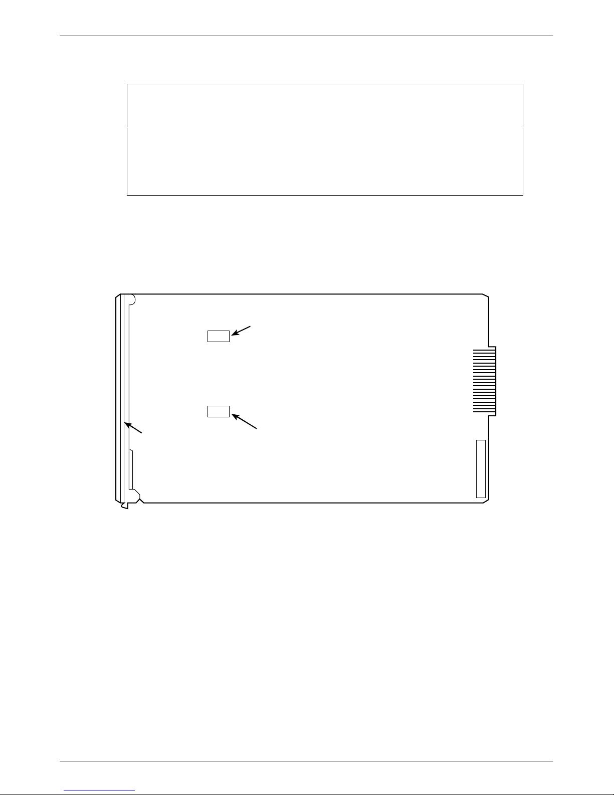
HARDWARE SWITCHES
Switches on the TDM and MCMP circuit cards are for factory test purposes only, and should not be changed.
S2
HANDLING PRECAUTIONS
FOR
ST ATIC-SENSITIVE DEVICES
REAR
(MUST BE IN
THE ON POSITION)
S1
*
FA CEPLATE
*
SWITCH S1 ONLY APPEARS ON THE MCMP CIRCUIT CARDS.
(MUST BE IN
THE ON POSITION)
Figure 1. Modular TDM or MCMP Circuit Card Hardware Switch Locations
REMOVING THE INSTALLED MODULAR 3611 DSU
FROM THE CARRIER
T o remove an installed Modular 3611 DSU, perform the following steps:
1. Use a Phillips screwdriver to loosen the screw holding the circuit pack lock on the Modular 3611 DSU,
and rotate the lock to the open position (Figure 2).
494-12966b
2 December 1999 3611-A2-GZ43-30
 Loading...