

Page 1

COMSPHERE
3600 SERIES
DATA SERVICE UNITS
MODELS 3610 AND 3611
TIME DIVISION MULTIPLEXER,
MULTICHANNEL MULTIPOINT, AND
DIGITAL BRIDGE OPTIONS
APPLICATIONS GUIDE
Document No. 3610-A2-GB41-60
March 1999
Page 2

COMSPHERE 3600 Series Data Service Units
COMSPHERE 3600 Series Data Service Units
Models 3610 and 3611
Time Division Multiplexer, Multichannel Multipoint, and Digital Bridge Options
Applications Guide
3610-A2-GB41-60
7th Edition (March 1999)
Changes and enhancements to the product and to the information herein will be documented and issued as a new release to this manual.
Warranty, Sales, Service, and Training Information
Contact your local sales representative, service representative, or distributor directly for any help needed. For additional information
concerning warranty, sales, service, repair, installation, documentation, training, distributor locations, or Paradyne worldwide office
locations, use one of the following methods:
• Internet: Visit the Paradyne World Wide Web site at www.paradyne.com. (Be sure to register your warranty there. Select
Service & Support → Warranty Registration.)
• Telephone: Call our automated system to receive current information by fax or to speak with a company representative.
— Within the U.S.A., call 1-800-870-2221
— Outside the U.S.A., call 1-727-530-2340
Document Feedback
We welcome your comments and suggestions about this document. Please mail them to Technical Publications, Paradyne Corporation,
8545 126th Ave. N., Largo, FL 33773, or send e-mail to userdoc@paradyne.com. Include the number and title of this document in
your correspondence. Please include your name and phone number if you are willing to provide additional clarification.
Trademarks
All products and services mentioned herein are the trademarks, service marks, registered trademarks or registered service marks of their
respective owners.
Printed on recycled paper
COPYRIGHT 1999 Paradyne Corporation. All rights reserved.
This publication is protected by federal copyright law. No part of this publication may be copied or distributed, transmitted, transcribed, stored in a retrieval system,
or translated into any human or computer language in any form or by any means, electronic, mechanical, magnetic, manual or otherwise, or disclosed to third parties
without the express written permission of Paradyne Corporation, 8545 126th Avenue North, P.O. Box 2826, Largo, Florida 33779-2826.
Paradyne Corporation makes no representation or warranties with respect to the contents hereof and specifically disclaims any implied warranties of merchantability
or fitness for a particular purpose. Further, Paradyne Corporation reserves the right to revise this publication and to make changes from time to time in the contents
hereof without obligation of Paradyne Corporation to notify any person of such revision or changes.
A March 1999 3610-A2-GB41-60
Page 3

!
Important Safety Instructions
1. Read and follow all warning notices and instructions marked on the product or
included in the manual.
2. This product is intended to be used with a 3-wire grounding type plug — a plug which
has a grounding pin. This is a safety feature. Equipment grounding is vital to ensure
safe operation. Do not defeat the purpose of the grounding type plug by modifying
the plug or using an adaptor.
Prior to installation, use an outlet tester or a voltmeter to check the ac receptacle for
the presence of earth ground. If the receptacle is not properly grounded, the
installation must not continue until a qualified electrician has corrected the problem.
If a 3-wire grounding type power source is not available, consult a qualified
electrician to determine another method of grounding the equipment.
3. Slots and openings in the cabinet are provided for ventilation. To ensure reliable
operation of the product and to protect it from overheating, these slots and openings
must not be blocked or covered.
4. Do not allow anything to rest on the power cord and do not locate the product where
persons will walk on the power cord.
Safety Instructions
5. Do not attempt to service this product yourself, as opening or removing covers may
expose you to dangerous high voltage points or other risks. Refer all servicing to
qualified service personnel.
6. General purpose cables are provided with this product. Special cables, which may be
required by the regulatory inspection authority for the installation site, are the
responsibility of the customer.
7. When installed in the final configuration, the product must comply with the applicable
Safety Standards and regulatory requirements of the country in which it is installed. If
necessary, consult with the appropriate regulatory agencies and inspection
authorities to ensure compliance.
8. A rare phenomenon can create a voltage potential between the earth grounds of two
or more buildings. If products installed in separate buildings are interconnected, the
voltage potential may cause a hazardous condition. Consult a qualified electrical
consultant to determine whether or not this phenomenon exists and, if necessary,
implement corrective action prior to interconnecting the products.
In addition, if the equipment is to be used with telecommunications circuits, take the
following precautions:
– Never install telephone wiring during a lightning storm.
– Never install telephone jacks in wet locations unless the jack is specifically designed
for wet locations.
– Never touch uninsulated telephone wires or terminals unless the telephone line has
been disconnected at the network interface.
– Use caution when installing or modifying telephone lines.
– Avoid using a telephone (other than a cordless type) during an electrical storm.
There may be a remote risk of electric shock from lightning.
– Do not use the telephone to report a gas leak in the vicinity of the leak.
B3610-A2-GB41-60 March 1999
Page 4

COMSPHERE 3600 Series Data Service Units
Notices
! ! ! ! !
!
! !!
C March 1999 3610-A2-GB41-60
Page 5

Table of Contents
Preface
About this Guide vii. . . . . . . . . . . . . . . . . . . . . . . . . . . . . . . . . . . . . . . . . .
How to Use this Guide vii. . . . . . . . . . . . . . . . . . . . . . . . . . . . . . . . . . . . . .
Related Documents viii. . . . . . . . . . . . . . . . . . . . . . . . . . . . . . . . . . . . . . . .
Reference Documents viii. . . . . . . . . . . . . . . . . . . . . . . . . . . . . . . . . . . . . .
1. Overview
Overview 1-1. . . . . . . . . . . . . . . . . . . . . . . . . . . . . . . . . . . . . . . . . . . . . . . .
Standard Features 1-2. . . . . . . . . . . . . . . . . . . . . . . . . . . . . . . . . . . . . . . . . .
Optional Features 1-2. . . . . . . . . . . . . . . . . . . . . . . . . . . . . . . . . . . . . . . . . .
Models 1-6. . . . . . . . . . . . . . . . . . . . . . . . . . . . . . . . . . . . . . . . . . . . . . . . . .
DBM T ypes 1-9. . . . . . . . . . . . . . . . . . . . . . . . . . . . . . . . . . . . . . . . . . . . . .
Government Requirements 1-9. . . . . . . . . . . . . . . . . . . . . . . . . . . . . . . . . .
Equipment Warranty and Support 1-9. . . . . . . . . . . . . . . . . . . . . . . . . . . . .
2. Model 3610 Installation
Overview 2-1. . . . . . . . . . . . . . . . . . . . . . . . . . . . . . . . . . . . . . . . . . . . . . . .
Hardware Straps 2-2. . . . . . . . . . . . . . . . . . . . . . . . . . . . . . . . . . . . . . . . . . .
Changing Hardware Settings 2-4. . . . . . . . . . . . . . . . . . . . . . . . . . . . . . . . .
Electrical Connection 2-8. . . . . . . . . . . . . . . . . . . . . . . . . . . . . . . . . . . . . . .
Network Diagnostic Connection 2-10. . . . . . . . . . . . . . . . . . . . . . . . . . . . . .
Software Configuration 2-10. . . . . . . . . . . . . . . . . . . . . . . . . . . . . . . . . . . . .
Network and LADS Connections 2-11. . . . . . . . . . . . . . . . . . . . . . . . . . . . .
DSU DTE Connection 2-11. . . . . . . . . . . . . . . . . . . . . . . . . . . . . . . . . . . . . .
Verification Testing 2-12. . . . . . . . . . . . . . . . . . . . . . . . . . . . . . . . . . . . . . . .
Adding a TDM/Flex or MCMP/Flex to an Installed Model 3610
DSU 2-13. . . . . . . . . . . . . . . . . . . . . . . . . . . . . . . . . . . . . . . . . . . . . . . . . .
Getting Started 2-14. . . . . . . . . . . . . . . . . . . . . . . . . . . . . . . . . . . . . . . . . . . .
Removing the DSU from Its Base 2-15. . . . . . . . . . . . . . . . . . . . . . . . . . . . .
Installing a TDM/Flex or MCMP/Flex 2-15. . . . . . . . . . . . . . . . . . . . . . . . .
Reassembling the Unit 2-16. . . . . . . . . . . . . . . . . . . . . . . . . . . . . . . . . . . . . .
i3610-A2-GB41-60 March 1999
Page 6

COMSPHERE 3600 Series Data Service Units
3. Model 3611 Installation
4. Principles of Operation
Overview 3-1. . . . . . . . . . . . . . . . . . . . . . . . . . . . . . . . . . . . . . . . . . . . . . . .
Hardware Straps 3-3. . . . . . . . . . . . . . . . . . . . . . . . . . . . . . . . . . . . . . . . . . .
Software Configuration 3-4. . . . . . . . . . . . . . . . . . . . . . . . . . . . . . . . . . . . .
Verification Testing 3-5. . . . . . . . . . . . . . . . . . . . . . . . . . . . . . . . . . . . . . . .
Adding a TDM or MCMP to an Installed Model 3611 DSU 3-6. . . . . . . . .
Removing TDM or MCMP from an Installed Model 3611 DSU 3-13. . . . .
Overview 4-2. . . . . . . . . . . . . . . . . . . . . . . . . . . . . . . . . . . . . . . . . . . . . . . .
Network T erminology 4-2. . . . . . . . . . . . . . . . . . . . . . . . . . . . . . . . . . . . . .
Modes Of Operation 4-4. . . . . . . . . . . . . . . . . . . . . . . . . . . . . . . . . . . . . . .
Time Division Multiplexing 4-5. . . . . . . . . . . . . . . . . . . . . . . . . . . . . . . . . .
Multichannel Multipoint 4-21. . . . . . . . . . . . . . . . . . . . . . . . . . . . . . . . . . . .
Digital Bridge 4-35. . . . . . . . . . . . . . . . . . . . . . . . . . . . . . . . . . . . . . . . . . . . .
NMS Control 4-52. . . . . . . . . . . . . . . . . . . . . . . . . . . . . . . . . . . . . . . . . . . . .
SNA Diagnostic Interface 4-53. . . . . . . . . . . . . . . . . . . . . . . . . . . . . . . . . . .
5. DSU Operations
Overview 5-2. . . . . . . . . . . . . . . . . . . . . . . . . . . . . . . . . . . . . . . . . . . . . . . .
Diagnostic Control Panels 5-2. . . . . . . . . . . . . . . . . . . . . . . . . . . . . . . . . . .
Status Indicators 5-3. . . . . . . . . . . . . . . . . . . . . . . . . . . . . . . . . . . . . . . . . . .
Menu Structure 5-7. . . . . . . . . . . . . . . . . . . . . . . . . . . . . . . . . . . . . . . . . . . .
Status Branch 5-8. . . . . . . . . . . . . . . . . . . . . . . . . . . . . . . . . . . . . . . . . . . . .
Backup Branch 5-12. . . . . . . . . . . . . . . . . . . . . . . . . . . . . . . . . . . . . . . . . . . .
T est Branch 5-14. . . . . . . . . . . . . . . . . . . . . . . . . . . . . . . . . . . . . . . . . . . . . .
Configuration Branch 5-31. . . . . . . . . . . . . . . . . . . . . . . . . . . . . . . . . . . . . . .
Control Branch 5-43. . . . . . . . . . . . . . . . . . . . . . . . . . . . . . . . . . . . . . . . . . . .
Appendices
A. Data Service Unit Menu A-1. . . . . . . . . . . . . . . . . . . . . . . . . . . . . . . . .
B. Configuration Worksheets B-1. . . . . . . . . . . . . . . . . . . . . . . . . . . . . . .
C. Pin Assignments C-1. . . . . . . . . . . . . . . . . . . . . . . . . . . . . . . . . . . . . . .
D. Configuration Scenarios D-1. . . . . . . . . . . . . . . . . . . . . . . . . . . . . . . . .
Index
ii March 1999 3610-A2-GB41-60
Page 7

Table of Contents
List of Figures
Figure Page
1-1 Model 3610 DSU with TDM or MCMP 1-7. . . . . . . . . . . . . . . . . . . . . . . . . . . . . . . . . .
1-2 Model 3611 DSU with TDM or MCMP 1-8. . . . . . . . . . . . . . . . . . . . . . . . . . . . . . . . . .
2-1 Model 3610 TDM/Flex or MCMP/Flex Switch Locations 2-3. . . . . . . . . . . . . . . . . . . .
2-2 Model 3610 TDM/DSD or MCMP/DSD Circuit Card Switch Locations 2-3. . . . . . . . .
2-3 Opening the DSU 2-4. . . . . . . . . . . . . . . . . . . . . . . . . . . . . . . . . . . . . . . . . . . . . . . . . . . .
2-4 Assembling/Disassembling the TDM or MCMP 2-5. . . . . . . . . . . . . . . . . . . . . . . . . . . .
2-5 Changing TDM/Flex or MCMP/Flex Interface Compatibility 2-6. . . . . . . . . . . . . . . . .
2-6 Changing TDM/DSD or MCMP/DSD Interface Compatibility 2-7. . . . . . . . . . . . . . . .
2-7 Model 3610 DSU with TDM or MCMP 2-9. . . . . . . . . . . . . . . . . . . . . . . . . . . . . . . . . .
2-8 Disconnecting the DSU 2-14. . . . . . . . . . . . . . . . . . . . . . . . . . . . . . . . . . . . . . . . . . . . . . .
3-1 Non-Modular TDM/MCMP Circuit Card Switch Locations 3-3. . . . . . . . . . . . . . . . . . .
3-2 Modular TDM/MCMP Circuit Card Switch Locations 3-4. . . . . . . . . . . . . . . . . . . . . . .
3-3 Non-Modular TDM or MCMP Installation 3-9. . . . . . . . . . . . . . . . . . . . . . . . . . . . . . . .
3-4 COMSPHERE 3000 Series Carrier (Rear) 3-10. . . . . . . . . . . . . . . . . . . . . . . . . . . . . . . .
3-5 Modular TDM or MCMP Installation 3-11. . . . . . . . . . . . . . . . . . . . . . . . . . . . . . . . . . . .
4-1 Multipoint Transmission 4-3. . . . . . . . . . . . . . . . . . . . . . . . . . . . . . . . . . . . . . . . . . . . . .
4-2 Functional Representation of Point-to-Point Multiplexing 4-5. . . . . . . . . . . . . . . . . . . .
4-3 TDM Architecture and Signal Flow 4-7. . . . . . . . . . . . . . . . . . . . . . . . . . . . . . . . . . . . .
4-4 Single-Port Point-to-Point Circuit with Nondisruptive Diagnostics 4-8. . . . . . . . . . . . .
4-5 Multipoint Async-Compatible Network 4-9. . . . . . . . . . . . . . . . . . . . . . . . . . . . . . . . . .
4-6 Point-to-Point Multiplexing 4-10. . . . . . . . . . . . . . . . . . . . . . . . . . . . . . . . . . . . . . . . . . . .
4-7 TDM with Extended Circuit 4-11. . . . . . . . . . . . . . . . . . . . . . . . . . . . . . . . . . . . . . . . . . .
4-8 Digital Sharing 4-12. . . . . . . . . . . . . . . . . . . . . . . . . . . . . . . . . . . . . . . . . . . . . . . . . . . . . .
4-9 Multiplexing and Digital Sharing 4-13. . . . . . . . . . . . . . . . . . . . . . . . . . . . . . . . . . . . . . .
4-10 FEP Port Sharing 4-15. . . . . . . . . . . . . . . . . . . . . . . . . . . . . . . . . . . . . . . . . . . . . . . . . . . .
4-11 Case 1 – V.32 Backup for Subrate DDS 4-16. . . . . . . . . . . . . . . . . . . . . . . . . . . . . . . . . .
4-12 Case 2 – V.32 Backup for High-Speed DSU 4-17. . . . . . . . . . . . . . . . . . . . . . . . . . . . . . .
4-13 Case 3 – V.32 Backup for DSU with Extended Circuits 4-18. . . . . . . . . . . . . . . . . . . . . .
4-14 Case 4 – Switched 56 DBM Backup for DSU Operating at 56 kbps or Less 4-19. . . . . .
4-15 Case 5 – Aggregate Switched Backup for TDM Circuits Configuration 4-20. . . . . . . . .
4-16 Typical Parallel Networks 4-21. . . . . . . . . . . . . . . . . . . . . . . . . . . . . . . . . . . . . . . . . . . . .
4-17 Applications Combined on One DDS Multipoint Circuit with MCMP 4-22. . . . . . . . . .
4-18 MCMP Architecture and Signal Flow 4-24. . . . . . . . . . . . . . . . . . . . . . . . . . . . . . . . . . . .
4-19 MCMP with Independent Channels 4-26. . . . . . . . . . . . . . . . . . . . . . . . . . . . . . . . . . . . . .
4-20 MCMP with Digital Sharing 4-27. . . . . . . . . . . . . . . . . . . . . . . . . . . . . . . . . . . . . . . . . . .
4-21 Case 1 – Dedicated MCMP Backup with Switched 56 DBMs 4-28. . . . . . . . . . . . . . . . .
4-22 Case 2 – Backing Up the Channels to the Most Important Tributary Location 4-29. . . . .
4-23 Case 3 – Backing Up One Complete Channel (Partial Backup) 4-30. . . . . . . . . . . . . . . .
4-24 Case 3 – Backing Up One Complete Channel (Full Backup) 4-31. . . . . . . . . . . . . . . . . .
iii3610-A2-GB41-60 March 1999
Page 8

COMSPHERE 3600 Series Data Service Units
Figure Page
4-25 Case 4 – Backing Up (Up to) Three Channels via the FEP Port-Sharing Feature 4-32. .
4-26 Digital Bridge/DCE Interface 4-33. . . . . . . . . . . . . . . . . . . . . . . . . . . . . . . . . . . . . . . . . .
4-27 Aggregate Switched Backup for MCMP Circuit Configuration 4-34. . . . . . . . . . . . . . . .
4-28 Multipoint with Digital Bridging 4-35. . . . . . . . . . . . . . . . . . . . . . . . . . . . . . . . . . . . . . . .
4-29 Maximum Bridging Capability – Up to 20 Bridging Ports 4-36. . . . . . . . . . . . . . . . . . . .
4-30 Broadcasting Data Through the Digital Bridge 4-37. . . . . . . . . . . . . . . . . . . . . . . . . . . . .
4-31 Multipoint DDS Circuit in Partial Backup 4-39. . . . . . . . . . . . . . . . . . . . . . . . . . . . . . . . .
4-32 Tributary Addressing via DDS Connections 4-40. . . . . . . . . . . . . . . . . . . . . . . . . . . . . . .
4-33 Tributary Addressing via Backup Connections 4-41. . . . . . . . . . . . . . . . . . . . . . . . . . . . .
4-34 Central-Site Bridging Architecture (9.6 kbps) – Normal Operation with
Partial Backup Possible 4-42. . . . . . . . . . . . . . . . . . . . . . . . . . . . . . . . . . . . . . . . . . . . .
4-35 Central-Site Bridging Architecture (9.6 kbps) – Partial Backup in Effect 4-43. . . . . . . .
4-36 Central-Site Bridging Architecture (56 kbps) – Inactive Digital Bridge 4-44. . . . . . . . . .
4-37 Central-Site Bridging Architecture (56 kbps) – Active Digital Bridge 4-45. . . . . . . . . . .
4-38 Bridged LADS Operation 4-50. . . . . . . . . . . . . . . . . . . . . . . . . . . . . . . . . . . . . . . . . . . . .
4-39 Bridged LADS Architecture and Signal Flow 4-51. . . . . . . . . . . . . . . . . . . . . . . . . . . . . .
4-40 Digital Bridge/DSU Interface 4-52. . . . . . . . . . . . . . . . . . . . . . . . . . . . . . . . . . . . . . . . . .
4-41 Sample Configuration and LPDA-2 Addressing 4-54. . . . . . . . . . . . . . . . . . . . . . . . . . . .
4-42 Dial Backup with LPDA-2 Configuration 4-55. . . . . . . . . . . . . . . . . . . . . . . . . . . . . . . . .
4-43 Multipoint Dial Backup with LPDA-2 4-56. . . . . . . . . . . . . . . . . . . . . . . . . . . . . . . . . . .
4-44 Multiplexing with TDM (LPDA-2 Monitoring) 4-57. . . . . . . . . . . . . . . . . . . . . . . . . . . .
4-45 Multiplexing with MCMP (LPDA-2 Monitoring) 4-57. . . . . . . . . . . . . . . . . . . . . . . . . . .
4-46 Digital Sharing in a Point-to-Point Circuit 4-58. . . . . . . . . . . . . . . . . . . . . . . . . . . . . . . .
4-47 Digital Sharing in a Multipoint Circuit 4-59. . . . . . . . . . . . . . . . . . . . . . . . . . . . . . . . . . .
4-48 Digital Sharing in a TDM Circuit (LPDA-2 Monitoring) 4-60. . . . . . . . . . . . . . . . . . . . .
4-49 Digital Sharing in an MCMP Circuit (LPDA-2 Monitoring) 4-61. . . . . . . . . . . . . . . . . .
5-1 Model 3611 DSU and TDM Faceplates 5-3. . . . . . . . . . . . . . . . . . . . . . . . . . . . . . . . . . .
5-2 Model 3611 DSU and MCMP Faceplates 5-4. . . . . . . . . . . . . . . . . . . . . . . . . . . . . . . . .
5-3 DBM-V, DBM-S, and DBM-D Faceplates 5-4. . . . . . . . . . . . . . . . . . . . . . . . . . . . . . . .
5-4 Device T est 5-16. . . . . . . . . . . . . . . . . . . . . . . . . . . . . . . . . . . . . . . . . . . . . . . . . . . . . . . . .
5-5 Local Loopback 5-17. . . . . . . . . . . . . . . . . . . . . . . . . . . . . . . . . . . . . . . . . . . . . . . . . . . . .
5-6 DTE Loopback on Port 2 5-19. . . . . . . . . . . . . . . . . . . . . . . . . . . . . . . . . . . . . . . . . . . . . .
5-7 Digital Loopback 5-20. . . . . . . . . . . . . . . . . . . . . . . . . . . . . . . . . . . . . . . . . . . . . . . . . . . .
5-8 Remote Digital Loopback 5-22. . . . . . . . . . . . . . . . . . . . . . . . . . . . . . . . . . . . . . . . . . . . .
5-9 Bilateral Loopback 5-24. . . . . . . . . . . . . . . . . . . . . . . . . . . . . . . . . . . . . . . . . . . . . . . . . . .
5-10 Digital Test 5-26. . . . . . . . . . . . . . . . . . . . . . . . . . . . . . . . . . . . . . . . . . . . . . . . . . . . . . . . .
5-11 End-to-End Test 5-28. . . . . . . . . . . . . . . . . . . . . . . . . . . . . . . . . . . . . . . . . . . . . . . . . . . . .
5-12 Bit Error Rate Tests in TDM or MCMP Mode 5-30. . . . . . . . . . . . . . . . . . . . . . . . . . . . .
5-13 Choosing Mode of Operation and Setting Configuration Options 5-35. . . . . . . . . . . . . .
C-1 TDM Interface Cable (Feature Number 3600-F2-500) C-2. . . . . . . . . . . . . . . . . . . . . . .
C-2 Digital Bridge Interface Cable (Feature Number 3600-F2-501) C-5. . . . . . . . . . . . . . . .
C-3 Pin Locations on the 60-Position High-Density Connector of the Non-Modular
Carrier-Mounted TDM/MCMP Circuit Card C-8. . . . . . . . . . . . . . . . . . . . . . . . . . . . .
C-4 Modular DSU V.35 Adapter (3000-F1-510) C-12. . . . . . . . . . . . . . . . . . . . . . . . . . . . . . .
C-5 6-Port Connector Module (Part Number 870-1700-0011) C-14. . . . . . . . . . . . . . . . . . . . .
C-6 6-Port V.35 Interconnect Cable (Feature Number 3600-F3-500) C-16. . . . . . . . . . . . . . .
D-1 TDM Configuration: Scenario 1 – Two Synchronous Channels D-2. . . . . . . . . . . . . . . .
D-2 TDM Configuration: Scenario 2 – Switched 56 kbps Dial Backup D-4. . . . . . . . . . . . .
D-3 Digital Bridge Configuration: Automatic Partial Backup – Dial Backup
Not Active D-6. . . . . . . . . . . . . . . . . . . . . . . . . . . . . . . . . . . . . . . . . . . . . . . . . . . . . . .
D-4 Digital Bridge Configuration: Automatic Partial Backup – Dial Backup Active D-7. . .
D-5 Digital Bridge Configuration: Full Backup – Dial Backup Active D-8. . . . . . . . . . . . . .
D-6 Multipoint Full Dial Backup with Nondisruptive Diagnostics Configuration D-11. . . . . .
iv March 1999 3610-A2-GB41-60
Page 9

Table of Contents
Figure Page
D-7 Extended Bridge Configuration: Automatic Partial Backup –
Dial Backup Not Active D-15. . . . . . . . . . . . . . . . . . . . . . . . . . . . . . . . . . . . . . . . . . . . .
D-8 Extended Bridge Configuration: Automatic Partial Backup Active –
Dial Backup Active for All Drops D-16. . . . . . . . . . . . . . . . . . . . . . . . . . . . . . . . . . . . .
D-9 Extended Bridge Configuration: Automatic Partial Backup Active –
Dial Backup Active for T wo Drops D-17. . . . . . . . . . . . . . . . . . . . . . . . . . . . . . . . . . . .
D-10 NMS-Controlled Full Backup Configuration – Dial Backup Not Active D-20. . . . . . . . .
D-11 NMS-Controlled Full Backup Configuration – Dial Backup Active D-21. . . . . . . . . . . . .
D-12 MCMP using FEP Port-Sharing Configuration D-26. . . . . . . . . . . . . . . . . . . . . . . . . . . . .
D-13 Dedicated MCMP Backup Configuration with Switched 56 DBMs D-27. . . . . . . . . . . . .
D-14 MCMP FEP Port-Sharing Configuration – Dial Backup Not Active D-30. . . . . . . . . . . .
D-15 MCMP FEP Port-Sharing Configuration – Dial Backup Active D-31. . . . . . . . . . . . . . . .
v3610-A2-GB41-60 March 1999
Page 10

COMSPHERE 3600 Series Data Service Units
Table Page
4-1 LADS Connection Distances 4-48. . . . . . . . . . . . . . . . . . . . . . . . . . . . . . . . . . . . . . . . . . .
5-1 TDM and MCMP Status Indicators (Model 3611 Only) 5-5. . . . . . . . . . . . . . . . . . . . . .
5-2 DSU with TDM or MCMP and DBM-V/DBM-S/DBM-D Status Indicators 5-6. . . . . .
5-3 DTE Lead Status Codes 5-10. . . . . . . . . . . . . . . . . . . . . . . . . . . . . . . . . . . . . . . . . . . . . . .
5-4 Circuit Quality Measurements 5-11. . . . . . . . . . . . . . . . . . . . . . . . . . . . . . . . . . . . . . . . . .
5-5 Backup Branch Menu Selections 5-13. . . . . . . . . . . . . . . . . . . . . . . . . . . . . . . . . . . . . . . .
5-6 Digital T est Results 5-27. . . . . . . . . . . . . . . . . . . . . . . . . . . . . . . . . . . . . . . . . . . . . . . . . .
5-7 End-to-End Test Results 5-28. . . . . . . . . . . . . . . . . . . . . . . . . . . . . . . . . . . . . . . . . . . . . .
5-8 Bit Error Rate T est Results 5-29. . . . . . . . . . . . . . . . . . . . . . . . . . . . . . . . . . . . . . . . . . . .
5-9 Complete List of MUX Setup Configuration Options 5-36. . . . . . . . . . . . . . . . . . . . . . . .
5-10 Complete List of MUX Port Configuration Options 5-38. . . . . . . . . . . . . . . . . . . . . . . . .
5-11 Poll List Menu Options 5-40. . . . . . . . . . . . . . . . . . . . . . . . . . . . . . . . . . . . . . . . . . . . . . .
5-12 Directory Entry and Password Characters 5-42. . . . . . . . . . . . . . . . . . . . . . . . . . . . . . . . .
5-13 Control Branch Menu Options 5-43. . . . . . . . . . . . . . . . . . . . . . . . . . . . . . . . . . . . . . . . . .
C-1 Time Division Multiplexer Connector Used with Non-Modular TDM C-2. . . . . . . . . . .
C-2 Digital Bridge Connector Used with Non-Modular TDM/MCMP C-5. . . . . . . . . . . . . .
C-3 60-Position High-Density Connector (TDM/MCMP Ports 2 through 6 for
Model 3611 DSU) C-9. . . . . . . . . . . . . . . . . . . . . . . . . . . . . . . . . . . . . . . . . . . . . . . . .
C-4 EIA-232-D/V.24 Connector (Port 1) C-10. . . . . . . . . . . . . . . . . . . . . . . . . . . . . . . . . . . . .
C-5 V.35 Connector (Port 1) C-11. . . . . . . . . . . . . . . . . . . . . . . . . . . . . . . . . . . . . . . . . . . . . . .
C-6 Model 3610 (Ports 2 – 6) and Modular DSU 25-Pin V.35 Connector C-13. . . . . . . . . . . .
C-7 EIA-232/V.24 TDM/MCMP Connector (Modular and
Standalone – Ports 2 through 6) C-15. . . . . . . . . . . . . . . . . . . . . . . . . . . . . . . . . . . . . . .
C-8 6-Port V.35 Interconnect Cable Connector C-17. . . . . . . . . . . . . . . . . . . . . . . . . . . . . . . .
List of Tables
vi March 1999 3610-A2-GB41-60
Page 11

Preface
About this Guide
This applications guide is intended as a supplement to
the operator’s guide; it only contains installation and
operation information that is specific to the Time Division
Multiplexer (TDM), Multichannel Multipoint (MCMP),
and digital bridge options for the COMSPHEREr 3600
Series Data Service Units (DSUs), Models 3610 and 3611.
Since a DBM-V, DBM-S, or DBM-D is only used in
digital bridge configurations, information specific to these
circuit cards is included in this applications guide, along
with SNA Diagnostic Interface information as it applies to
TDM or MCMP configurations. However, a DBM-V,
DBM-S, or DBM-D operates like an internal Dial Backup
Module (DBM), so if your application uses a DBM-V,
DBM-S, or DBM-D, refer to the other applications guide.
Order the COMSPHERE 3600 Series Data Service
Units, Models 3610 and 3611, Operator’s Guide for the
technical specifications for the DSU and all of its options,
basic DSU installation and operation information,
verification of network operation, all configuration
options tables and worksheets, DCP messages for all
options, and troubleshooting flowcharts.
DATAPHONEr II and Diagnostic Microcomputer (DMC)
Network Management System (NMS) references are also
provided, along with a complete equipment list and
glossary .
Order the COMSPHERE 3600 Series Data Service
Units, Models 3610 and 3611, Dial Backup Module and
SNA Diagnostic Interface Options, Applications Guide if
your application uses these options as part of its
configuration, or if your application uses DBM-Vs,
DBM-Ss, or DBM-Ds. It also provides a NetView t
commands reference for your convenience.
How to Use this Guide
Chapter 1 gives a general overview of the features for
the 3600 Series DSU and its TDM and MCMP options.
Refer to this chapter for a summary of feature capability.
Chapter 2 explains how to install and set up a
Model 3610 (standalone) DSU-TDM/Flex or
DSU-MCMP/Flex, or if you have added a TDM/Flex or
MCMP/Flex to your DSU. If you ordered a TDM/DSD or
MCMP/DSD, refer to this chapter to change interface
settings.
Chapter 3 explains how to install and set up a
Model 3611 (carrier-mounted) DSU-TDM or
DSU-MCMP, or to add a TDM or MCMP to your DSU.
Chapter 4 familiarizes you with the basic principles
underlying TDM, MCMP, and digital bridge operation. It
also explains how SNA Diagnostic Interface operation is
affected when using these features.
Chapter 5 identifies and discusses how the DSU
functions differently or has different selections available
when the TDM or MCMP is installed, or when a DBM-V,
DBM-S, or DBM-D is installed.
Appendix A provides a summary of the DSU’s menu
structure. Refer to the menu tree as you proceed through
the menu via the DCP (or SDCP if you have a Model
3611 DSU).
Appendix B provides a summary of all of the
configuration options in the form of Configuration
Worksheets, along with a suggestion for how the
worksheets can be used.
Appendix C provides pin assignments for TDM or
MCMP interfaces and cables.
Appendix D shows typical system configurations
utilizing TDM, MCMP, and digital bridging. These
configurations also indicate the configuration options that
should be set to duplicate these scenarios for your own
applications.
Index
vii3610-A2-GB41-60 March 1999
Page 12

COMSPHERE 3600 Series Data Service Units
Related Documents
Basic DSU product documentation includes the
following:
3610-A2-GB46 COMSPHERE 3600 Series
Data Service Units, Models
3610 and 3611, User’s Guide
3610-A2-GB48 COMSPHERE 3600 Series
Data Service Units, Models
3610 and 3611, Time Division
Multiplexer, Multichannel
Multipoint, and Digital Bridge
Options, User’s Guide
Supplement
Should more detail about how the DSU operates be
required, the following additional documentation may be
ordered:
3610-A2-GB91 COMSPHERE 3600 Series
Data Service Units,
Models 3610 and 3611,
Operator’s Guide
3610-A2-GN32 COMSPHERE 3600 Series
Data Service Units,
Models 3610 and 3611, Dial
Backup Module and SNA
Diagnostic Interface Options,
Applications Guide
Other product documentation includes the following:
3000-A2-GA31 COMSPHERE 3000 Series
Carrier, Installation Manual
3000-A2-GB41 COMSPHERE –48 Vdc
Central Office Power Unit,
Installation Guide
3610-A2-GB42 COMSPHERE 3600 Series
Data Services Units, Models
3610 and 3611, Secondary
Channel Applications
Supplement
6800-A2-GB31 COMSPHERE 6800 Series
Network Management System
Communications Products
Support Command Reference
Manual
999-100-1961S DATAPHONE II 2600 Series
Data Service Units, User’s
Manual
Contact your sales representative for additional product
documentation.
Paradyne documents are also available on the World
Wide Web at www.paradyne.com. Select Library →
Technical Manuals.
Reference Documents
• AT&T Technical Reference 41458.
• AT&T T echnical Reference 61330.
• AT&T Technical Reference 62310 – 1987.
• Bell Canada DCTE Specifications.
• Bell Communications Research T echnical
Reference Publication 41028.
• CCITT V.35 (ISO 2593).
• EIA-232-D/V.24 (ISO 2110).
• Integrated Network Corporation Compatibility
Bulletin CB-INC-101.
• Northern T elecom NIS S204-2e 1986.
• Pacific Bell PUB L-780035-PB/NB.
• Pacific Bell PUB L-780036-PB/NB.
6700-A2-GB41 COMSPHERE 6700 Series
Network Management System,
User’s Guide, Security
Manager Feature Supplement
6700-A2-GY31 COMSPHERE 6700 Series
Network Management System,
User’s Guide
viii March 1999 3610-A2-GB41-60
Page 13

Overview
Overview 1-1. . . . . . . . . . . . . . . . . . . . . . . . . . . . . . . . . . . . . . . . . . . . . . . . . . . . . . . . . . . . . . . . . . . . . . . . . .
Standard Features 1-2. . . . . . . . . . . . . . . . . . . . . . . . . . . . . . . . . . . . . . . . . . . . . . . . . . . . . . . . . . . . . . . . . . .
Optional Features 1-2. . . . . . . . . . . . . . . . . . . . . . . . . . . . . . . . . . . . . . . . . . . . . . . . . . . . . . . . . . . . . . . . . . .
DSU with TDM Capability 1-2. . . . . . . . . . . . . . . . . . . . . . . . . . . . . . . . . . . . . . . . . . . . . . . . . . . . . . . . .
DSU with MCMP Capability 1-4. . . . . . . . . . . . . . . . . . . . . . . . . . . . . . . . . . . . . . . . . . . . . . . . . . . . . . . .
DSU with Digital Bridge Capability 1-5. . . . . . . . . . . . . . . . . . . . . . . . . . . . . . . . . . . . . . . . . . . . . . . . . .
DSU with LPDA-2 Interoperability and TDM or MCMP 1-5. . . . . . . . . . . . . . . . . . . . . . . . . . . . . . . . . .
Models 1-6. . . . . . . . . . . . . . . . . . . . . . . . . . . . . . . . . . . . . . . . . . . . . . . . . . . . . . . . . . . . . . . . . . . . . . . . . . .
Model 3610 with TDM or MCMP 1-6. . . . . . . . . . . . . . . . . . . . . . . . . . . . . . . . . . . . . . . . . . . . . . . . . . . .
Model 3611 with TDM or MCMP 1-6. . . . . . . . . . . . . . . . . . . . . . . . . . . . . . . . . . . . . . . . . . . . . . . . . . . .
Models 3610 and 3611 with SNA Diagnostic Interface 1-6. . . . . . . . . . . . . . . . . . . . . . . . . . . . . . . . . . .
DBM Types 1-9. . . . . . . . . . . . . . . . . . . . . . . . . . . . . . . . . . . . . . . . . . . . . . . . . . . . . . . . . . . . . . . . . . . . . . . .
DBM-V 1-9. . . . . . . . . . . . . . . . . . . . . . . . . . . . . . . . . . . . . . . . . . . . . . . . . . . . . . . . . . . . . . . . . . . . . . . .
DBM-S 1-9. . . . . . . . . . . . . . . . . . . . . . . . . . . . . . . . . . . . . . . . . . . . . . . . . . . . . . . . . . . . . . . . . . . . . . . . .
DBM-D 1-9. . . . . . . . . . . . . . . . . . . . . . . . . . . . . . . . . . . . . . . . . . . . . . . . . . . . . . . . . . . . . . . . . . . . . . . .
Government Requirements 1-9. . . . . . . . . . . . . . . . . . . . . . . . . . . . . . . . . . . . . . . . . . . . . . . . . . . . . . . . . . . .
Equipment Warranty and Support 1-9. . . . . . . . . . . . . . . . . . . . . . . . . . . . . . . . . . . . . . . . . . . . . . . . . . . . . . .
1
Overview
The COMSPHEREr 3600 Series Data Service Units
(DSUs), Models 3610 and 3611, support communication
between computers and other data processing devices by
providing connections to digital transmission facilities.
The 3600 Series DSUs can be optioned with hardware to
support the following capabilities:
• Dial backup (point-to-point and multipoint).
• LPDA-2 (Link Problem Determination Aid,
Release 2) interoperability.
• Time Division Multiplexing (TDM).
• Multichannel Multipoint (MCMP).
• Digital bridge.
The time division multiplexing, multichannel
multipoint, digital bridge and multipoint backup
capabilities are discussed in this applications guide.
LPDA-2 interoperability, as it applies to applications
requiring installation of the TDM or MCMP option, is
also discussed in this guide.
The time division multiplexer (TDM) option, an
additional circuit card, supports time division
multiplexing and digital sharing for up to six ports. It can
serve as a digital bridge for multipoint dial backup and
multipoint local area data set (LADS) operation.
The multichannel multipoint (MCMP) option is a
circuit card that provides multipoint TDM capability. The
MCMP capability allows up to six independent
application programs to share one 56 kbps multipoint
circuit. Channel speeds can range from 1.2 to 48 kilobits
per second (kbps) and the sum of the speeds must be less
than or equal to 48 kbps.
The TDM can be software-defined to provide the TDM
or digital bridge capability; the MCMP option can be
software-defined to provide TDM, MCMP, or digital
bridge capability . However, only one of these capabilities
can be in effect at a time. The TDM cannot be upgraded to
support MCMP capability.
1-13610-A2-GB41-60 March 1999
Page 14

COMSPHERE 3600 Series Data Service Units
LPDA-2 interoperability is provided by the systems
network architecture (SNA) Diagnostic Interface option
that is installed on the DSU circuit card. It supports DSU
management from IBM’s NetViewt host-based network
management system (NMS), as well as management from
a Paradyne NMS or the DSU’s diagnostic control panel
(DCP). This option also supports DBM (including the
DBM-V, DBM-S, and DBM-D), TDM, MCMP , and
digital bridge capability.
Standard Features
The 3600 Series DSU, without any options, offers the
following features:
• Multispeed operation.
• Clear Channel capability.
• LADS operation.
• Asynchronous operation.
• Nondisruptive diagnostics.
• NMS control.
• Rate adaption.
• Aggregate switching.
• Diagnostic Control Panel control.
• Full tributary diagnostics.
• External dial backup.
Refer to the COMSPHERE 3600 Series Data Service
Units, Models 3610 and 3611, Operator’s Guide, which
can be ordered, for a description of these features.
NOTE
This applications guide is
designed to be used in
conjunction with the
COMSPHERE 3600 Series Data
Service Units, Models 3610 and
3611, Operator’s Guide
COMSPHERE 3600 Series Data
Service Units, Models 3610 and
3611, Dial Backup Module and
SNA Diagnostic Interface
Options, Applications Guide.
and the
Optional Features
This manual discusses the 3600 Series DSU with the
TDM or MCMP option; it also includes discussion of
DBM-Vs, DBM-Ss, or DBM-Ds, which are used in digital
bridging applications.
Most diagnostic tests and commands available to a
3600 Series DSU without the TDM or MCMP option are
also available with the TDM or MCMP option. Control of
a TDM/MCMP/digital bridge session can be performed
from the DCP, from an Async (Asynchronous) Terminal,
or from a COMSPHERE 6700 or 6800 Series NMS.
Options that provide point-to-point dial backup
capability and LPDA-2 interoperability without the TDM
or MCMP option are discussed in the COMSPHERE
3600 Series Data Service Units, Models 3610 and 361 1,
Dial Backup Module and SNA Diagnostic Interface
Options, Applications Guide.
DSU with TDM Capability
TDM capability allows up to six independent ports to
share one standard digital point-to-point facility. TDM
capability provides the following features:
• Port capacity. The TDM option allows up to six
independent ports. One port is provided on the
DSU, and five EIA-232 ports are provided on the
TDM circuit card. (For a Modular 3611 DSU, V.35
interface is at the top of the 6-port connector
module.)
There are two versions of the Model 3610
TDM/Flex: the 2-port TDM/Flex and the 6-port
TDM/Flex. With one of these features installed,
each port can be set as either an EIA-232 or V.35
interface. When a port other than Port 1 is used for
V.35 operation, a cable adapter is required (feature
number 3000-F1-510).
When a Model 3610 TDM/DSD (digital sharing
device) is ordered, Ports 2 through 6 are configured
for EIA-232 operation. With these models, you can
select either EIA-232 or V.35 operation for this port
group.
• Multiplexing. The TDM option provides time
division multiplexing for up to six independent
ports over one standard DDS (digital data service)
point-to-point facility.
• Line speeds. TDM capability operates at all line
speeds supported by the 3600 Series DSU: 2.4, 4.8,
9.6, 19.2, 38.4, 56, and 64 kbps full-duplex.
1-2 March 1999 3610-A2-GB41-60
Page 15

Overview
• Port speeds. Speeds of the individual TDM ports
(1 through 6) can be set to 1.2, 2, 2.4, 4, 4.4, 4.8,
7.2, 8.4, 9.2, 9.6, 12, 14.4, 16.8, 18, 18.8, 19.2,
28.8, 32, 38.4, 48, 56, or 64 kbps full-duplex. The
sum of the port speeds cannot exceed the line speed.
• Asynchronous operation. Although the DSU
provides synchronous transmission through the
DDS network, any one or more of the six ports can
be configured for asynchronous operation. The
TDM capability provides the asynchronous-tosynchronous conversion on these ports. In addition
to synchronous data rates, asynchronous data rates
of 150, 300, 600, 1200, and 1800 bps are supported.
The word size is 6 to 10 bits, and one or two stop
bits can be specified.
• Digital sharing. Two groups of consecutive ports
can be formed to share the same TDM channel. All
ports in a digital-sharing group operate at the same
speed and all receive the same data. When
configured for DSD port contention, only one port
at a time is allowed to send.
• FEP port sharing. FEP port sharing is a method of
connecting a front-end processor (FEP) to multiple
control DSUs/modems to broadcast the same
message over the network and the shared port. Up
to three separate FEP port-sharing groups can be
selected. Each group consists of two adjacent ports
(e.g., 1 and 2, 3 and 4, 5 and 6).
FEP data and control signal transmissions pass
through the odd-numbered port for broadcast onto a
TDM channel and the even-numbered port.
• Elastic store per port. The TDM capability
provides a transmit elastic store buffer for each port
to support extended circuits. Both digital and
analog extensions are supported.
• Switched-carrier emulation. In TDM
transmission, switched-carrier emulation for each
port is optional for both the inbound (toward the
control DSU) and outbound (from the tributary
DSU) directions.
• Digital bridge. The TDM can be configured to
perform a digital bridge function. The digital bridge
capability can support many applications, including
dedicated multipoint dial backup and multipoint
LADS operation.
• NMS control. A 3600 Series DSU with TDM has
the same diagnostic capabilities as a point-to-point
3600 Series DSU without the TDM option. Control
of a TDM session can be performed from the DCP
or from a 6700 or 6800 Series NMS.
• Async Terminal control. A Model 3610 DSU with
TDM can be controlled from a VT100-compatible
async terminal. When this feature is enabled, the
DSU is operated from the async terminal’s menu
and keyboard.
• Point-to-point backup. A 3600 Series DSU with
TDM can also have a DBM installed for
point-to-point dial backup. If backup is at a
different speed than the DSU’s speed, TDM
operation automatically changes to a second
predetermined port speed to support dial backup
operation at the lower speed.
• Aggregate switching. Aggregate switching
provides an additional mode of point-to-point dial
backup. When enabled, it provides an internal
aggregate data stream that includes diagnostics and
framing on the alternate EIA-232-D or V.35
interface of Port 1. The aggregate port can then be
connected to a DBM or an external dial backup unit
(DBU).
• External dial backup. An external DBU (e.g., a
3800 Series dial/lease modem) can provide backup
for a point-to-point DSU. By monitoring the Data
T erminal Ready (DTR) lead on the DTE port that
supports the aggregate data path, the 3600 Series
DSU can set up a backup session when the external
DBU receives an incoming call. The DTR lead of
the DSU’s alternate DTE port then switches the
data path. Using another method, the local
3600 Series DSU can initiate and terminate a
backup call by controlling the DTR lead of the
external DBU by controlling the Data Set Ready
(DSR) lead.
1-33610-A2-GB41-60 March 1999
Page 16

COMSPHERE 3600 Series Data Service Units
DSU with MCMP Capability
The MCMP capability is an enhancement to TDM and
allows up to six independent application programs to
share one standard 56 kbps multipoint facility. Only an
MCMP can be configured to provide MCMP capability
and provides the following features:
• Channel capacity. The channel capacity is six
channels, which can be assigned to any of the
physical ports. One port is provided on the DSU,
and one (2-port version) or five EIA-232 ports are
provided on the MCMP circuit card. Up to six
virtual multipoint circuits can exist over one
standard DDS multipoint facility.
There are two versions of the Model 3610
MCMP/Flex: the 2-port MCMP/Flex and the 6-port
MCMP/Flex. With one of these features installed,
each port can be set as either EIA-232 or V.35
interface. When a port other than Port 1 is used for
V.35 operation, a cable adapter is required (feature
number 3000-F1-510).
When a Model 3610 MCMP/DSD (an MCMP that
can operate as a digital sharing device) is ordered,
Ports 2 through 6 are configured for EIA-232
operation. You can select either EIA-232 or V.35
operation for this port group.
• Number of addressable devices. The MCMP
capability supports up to 40 tributary DSUs or
20 tributary DSUs with DBMs, each equipped with
an MCMP circuit card.
• Line speeds. The MCMP capability operates at
56 kbps full-duplex. The total usable bandwidth for
the port is an aggregate bit rate of up to 48 kbps.
• Digital sharing. Up to three digital-sharing groups
can be formed at each tributary site by assigning
channels to more than one port. Since all ports in a
digital-sharing group share the same channel, all
ports operate at the same speed and all receive the
same data.
With MCMP capability, digital sharing and
multiplexing can be in effect simultaneously at any
of the tributary sites.
• FEP port sharing. Up to three separate FEP
port-sharing groups can be selected when using the
MCMP option, each consisting of two adjacent
ports (e.g., 1 and 2, 3 and 4, 5 and 6). FEP
port-sharing is a method of connecting an FEP to
multiple control DSUs/modems to broadcast the
same message over the network and the shared port.
FEP data and control signal transmissions pass
through the odd-numbered port for broadcast onto a
TDM channel and the even-numbered port.
• Elastic store per port. The MCMP capability
provides a transmit elastic store buffer on each port
to support extended circuits. Both digital and
analog extensions are supported.
• Switched-carrier emulation. In MCMP
transmission, switched-carrier emulation for each
channel is standard inbound (toward the control
DSU) and optional outbound (from the tributary
DSU).
• Async Terminal control. A Model 3610 DSU with
MCMP can be controlled from an async terminal.
When this feature is enabled, the DSU is operated
from the async terminal’s menu and keyboard.
• Channel speeds. Speeds of the individual channels
can be arbitrarily set to 1.2, 2.4, 4.8, 7.2, 9.6, 12,
14.4, 16.8, 19.2, 38.4, or 48 kbps full-duplex. The
sum of the channel speeds cannot exceed 48 kbps.
• Dial backup. Dial backup using the aggregate
switching and extended bridge capabilities allow
for multipoint service restoration. When aggregate
switching is enabled, the DSU provides an internal
aggregate data stream that includes diagnostics and
• Asynchronous operation. Although the DSU
provides synchronous transmission through the
DDS network, any of the channels (ports) can be
configured for asynchronous operation. The MCMP
capability provides the asynchronous-tosynchronous conversion on these channels.
framing on the EIA-232-D and V.35 interfaces of
Port 1. The aggregate port (the DTE port not
selected under the General option set) can then be
connected to an extended bridge so the data can be
sent to multiple Switched 56 DBMs – either 2-wire
or 4-wire.
The channel speed choices are the same as those for
synchronous operation. The word size can range
from 6 to 10 bits, and one or two stop bits can be
specified. Asynchronous data rates of 150, 300,
600, 1200, and 1800 bps are also supported.
1-4 March 1999 3610-A2-GB41-60
Page 17

Overview
DSU with Digital Bridge Capability
The digital bridge capability is dedicated to a single
DSU, and the data terminal equipment (DTE) connected
to that DSU is usually the controlling DTE of a multipoint
network. Both TDM and MCMP can be configured to
provide the digital bridge capability. The digital bridge
capability can support many applications, including
dedicated multipoint dial backup and multipoint LADS
operation.
This capability is used primarily for dedicated
multipoint dial backup. A digital data service multipoint
network is backed up with public switched telephone
network (PSTN) or switched 56 kbps calls between the
central-site and remote-site DBMs that are tied together
by the digital bridge.
The digital bridge capability, when used to support
dedicated multipoint dial backup, provides the following
features:
• Number of tributaries. Dedicated multipoint dial
backup can back up as many as 20 tributary DSUs.
T o do this, four additional DSUs with TDM, each
configured for extended bridge (EBrdg), are
required.
• Multispeed operation. Multipoint dial backup
using the V.32 DBM or DBM-V operates at a
customer-specified rate of 2.4, 4.8, 9.6, 12, or
14.4 kbps full-duplex. Fallback (training at a lower
rate) is not allowed. Using either the 2-wire or
4-wire Switched 56 DBM (DBM-D or DBM-S,
respectively), the DBM operates at 56 kbps.
• Partial and full backup. Multipoint dial backup
can provide both partial and full backup on DDS
multipoint circuits. For partial backup, the DSU’s
rate must equal the DBM’s rate. Full backup must
be performed if the DSU’s rate is not equal to the
DBM’s rate.
• Restoration. When the DSU rate equals the DBM
rate, tributary DSUs can be configured to
automatically drop the backup connection and
switch back to the DDS facility when service has
been restored to the DDS network. When the DSU
rate is not equal to the DBM rate, restoration can
only be accomplished remotely from an NMS or
manually from the control DSU’s DCP.
• Setup. A backup session can be set up
automatically by the tributary DSUs (if the DSU’s
rate is equal to the DBM’s rate), controlled
remotely from an NMS, or initiated manually from
a control DSU’s shared diagnostic control panel
(SDCP).
DSU with LPDA-2 Interoperability and
TDM or MCMP
The SNA Diagnostic Interface firmware upgrade, using
the Release 2 Link Problem Determination Aid (LPDA-2)
protocol, is installed on the DSU circuit card. LPDA-2
interoperability provides the following features:
• Link Problem Determination Aid. This protocol
emulates IBM 5822 DSUs that use the LPDA-2
protocol, allowing the 3600 Series DSU to be
controlled from IBM’s NetView network
management program. With TDM or MCMP, this
option is only supported on Port 1. For digital
sharing, all ports are supported.
• NMS control. The 3600 Series DSUs operating
with the LPDA-2 option can respond to commands
from NetView, the NMS, the DSU’s DCP, or all
three.
• Full option support. With the LPDA-2 option
installed, all other 3600 Series DSU options are
accommodated: DBM, TDM, or MCMP.
• Security. The V.32 DBM or DBM-V, the 4-wire
Switched 56 DBM or DBM-S, or the 2-wire
Switched 56 DBM or DBM-D provide four levels
of call setup security: None, Password, Callback,
and Alarm. Alarm allows the DBM, DBM-V,
DBM-S, or DBM-D to answer only incoming calls
when there is a Facility Alarm on the DDS line.
1-53610-A2-GB41-60 March 1999
Page 18

COMSPHERE 3600 Series Data Service Units
Models
The 3600 Series DSUs are available in two models:
• Model 3610 is a standalone desktop unit.
• Model 3611 is a circuit card for installation in a
COMSPHERE 3000 Series Carrier.
NOTE
Except
where specifically noted,
all features and capabilities of the
3600 Series DSUs with the TDM
or MCMP option discussed in this
applications guide apply equally
to both models. However , the two
models are not interchangeable.
Model 3610 with TDM or MCMP
The housing of the Model 3610 DSU with TDM or
MCMP has an expanded base which is designed to
accommodate both the DSU circuit card and the TDM or
MCMP circuit card (Figure 1-1).
The TDM or MCMP circuit card provides up to five
additional 25-pin EIA-232 interface connectors (ports) on
the rear of the housing. These ports, together with the
DSU’s EIA-232-D/V.24 interface connector (Port 1),
provide for 2-port or 6-port multiplexing or digital
sharing.
A Model 3610 DSU with TDM/Flex or MCMP/Flex
may be a 2- or 6-port version. You can configure each
port independently to operate as either an EIA-232 or
V.35 interface. Ports are configured via the DCP, an async
terminal, or an NMS. When a port other than Port 1 is
used for V.35 operation, a cable adapter is required
(feature number 3000-F1-510).
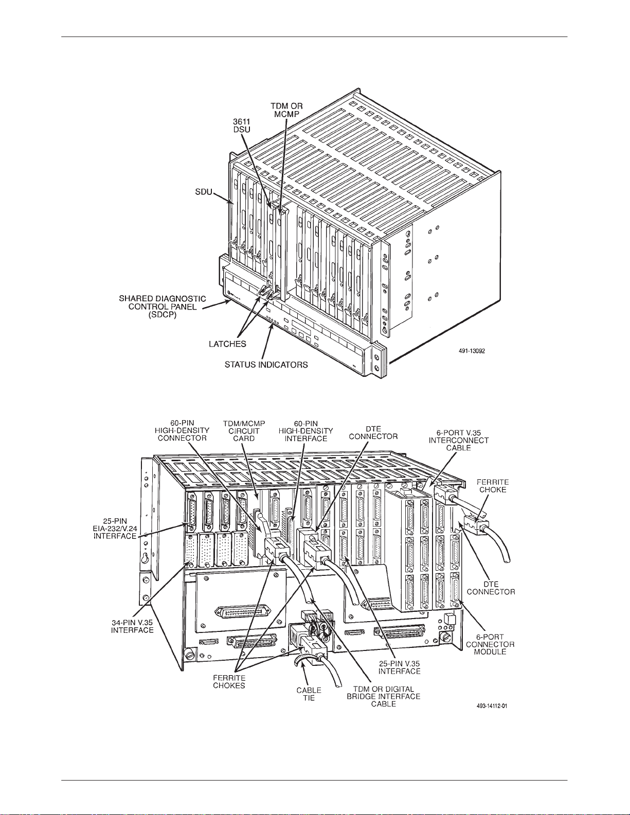
they fill two adjacent slots in the COMSPHERE 3000
Series Carrier.
There are two types of Model 3611 TDM or MCMP
circuit cards: non-modular and modular.
The non-modular TDM or MCMP provides a single
multiport interface connector mounted directly onto the
rear of the TDM or MCMP circuit card. The EIA-232-D/
V.24 or V.35 interface connector at the rear of the DSU is
Port 1; the TDM or MCMP multiport interface connector
provides five additional EIA-232 ports (2 through 6). A
special multiport cable fans out from the single multiport
interface connector to five individual EIA 25-pin DTE
connectors. Together with the Port 1 interface connector,
the multiport cable provides for 6-port multiplexing or
digital sharing.
The modular TDM or MCMP contains “gold finger”
contacts on the rear edge of the circuit card and is used
with the 6-port connector module that contains six DB25
connectors. There is one connector for each port and a
multiport cable is not needed. The 6-port connector
module also provides a 26-pin high-density D-type
connector for a V.35 interface for Port 1 and is located at
the top of the module. This connector requires a 6-port
V.35 Interconnect Cable that must be ordered separately.
The non-modular TDM or MCMP can be installed on a
non-modular or modular DSU, while the modular TDM or
MCMP can only be installed on a modular DSU. With the
non-modular TDM or MCMP, the DTE cables must be
removed before removing the DSU-TDM or DSU-MCMP
unit from the carrier. However, with the modular TDM or
MCMP, you can remove the DSU-TDM or DSU-MCMP
unit from the from of the carrier without disconnecting the
DTE cables from the rear of the carrier.
Low voltage ac power from the carrier’s backplane is
provided to the TDM or MCMP circuit card, and a power
supply on the TDM or MCMP circuit card produces the
regulated dc operating voltage.
When the TDM/DSD or MCMP/DSD (EIA-232/V.35)
is installed, you can select either EIA-232 or V.35
interface compatibility for Ports 2 through 6 by changing
the option card.
Model 3611 with TDM or MCMP
The Model 3611 DSU with TDM or MCMP consists of
a Model 3611 circuit card and a TDM or MCMP circuit
card that are physically connected (Figure 1-2). As a unit,
1-6 March 1999 3610-A2-GB41-60
Models 3610 and 3611 with
SNA Diagnostic Interface
The Models 3610 and 3611 with the SNA Diagnostic
Interface or LPDA-2 consist of a firmware upgrade that
allows the DSU to be controlled by NetView. A 3600
Series DSU can be ordered from the factory with this
option installed. This option can be also be field installed
by your Customer Support representative or upgraded by
Factory Service.
Page 19
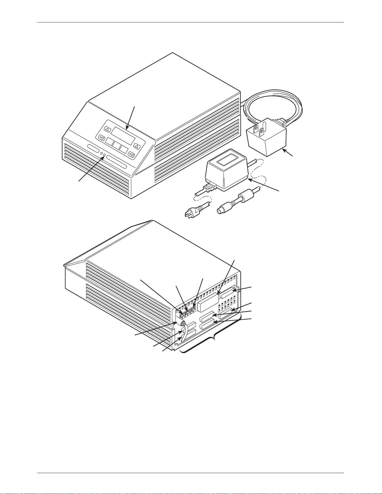
COMSPHERE 3610
STATUS
INDICATORS
Overview
DIAGNOSTIC
CONTROL
PANEL
WALL-MOUNT
AC TRANSFORMER
TABLE-TOP
AC TRANSFORMER
INTERFACE
LOW VOLTAGE
AC POWER IN
Figure 1-1. Model 3610 DSU with TDM or MCMP
DDS
PORT 5
PORT 6
DBM
INTERFACE
V.35 INTERFACE
(PORT 1)
NETWORK
DIAGNOSTIC
INTERFACE
EIA232D/V.24
INTERFACE
(PORT 1)
PORT 2
PORT 3
PORT 4
ADDITIONAL EIA-232
INTERFACES
PORT NUMBERS 2 – 6
496-13091-04
1-73610-A2-GB41-60 March 1999
Page 20
COMSPHERE 3600 Series Data Service Units
Figure 1-2. Model 3611 DSU with TDM or MCMP
1-8 March 1999 3610-A2-GB41-60
Page 21

Overview
DBM Types
Three dial backup modules (DBMs) are available. A
DBM is optional and provides an alternate data path in
case the digital connection fails. Each of the three DBM
types listed below occupy one slot in the COMSPHERE
3000 Series Carrier.
DBM-V
A DBM-V is used for point-to-point dial backup and
provides multipoint dial backup with a digital bridge. The
DBM-V provides a carrier-mounted, 14.4 kbps V.32bis
module that is compatible with the DBM associated with
3600 Series DSUs and with a COMSPHERE 6700 or
6800 Series NMS.
DBM-S
A DBM-S provides the capability to utilize the 4-wire
switched 56 kbps digital service to back up a failed
multipoint DDS circuit via a digital bridge. It is
particularly useful in an MCMP backup environment. The
DBM-S can be used on switching services that are
compatible with AT&T, MCIr, and US SPRINTr using
dedicated 4-wire access.
Government Requirements
For the Government Requirements and specific
instructions pertaining to connection to the telephone
network, refer to the COMSPHERE 3600 Series Data
Service Units, Models 3610 and 361 1, User’s Guide.
Equipment W arranty
and Support
For the Equipment Warranty and Support instructions,
refer to the COMSPHERE 3600 Series Data Service
Units, Models 3610 and 3611, User’s Guide.
NOTE
If the DSU-TDM or DSU-MCMP
was ordered as an integrated
unit and needs repair, contact
your service representative;
not remove the TDM or MCMP
from the DSU
.
do
DBM-D
A DBM-D provides the capability to utilize the 2-wire
switched 56 kbps digital service to back up a failed
multipoint DDS circuit via a digital bridge. It is
particularly useful in an MCMP backup environment. The
DBM-D can be used on switching services that are
compatible with Northern T elecom’s DataPatht service
using dedicated 2-wire access.
NOTE
References to DBM operation in
this guide also apply to a DBM-V,
DBM-S, or DBM-D.
1-93610-A2-GB41-60 March 1999
Page 22

COMSPHERE 3600 Series Data Service Units
1-10 March 1999 3610-A2-GB41-60
Page 23

Model 3610 Installation
Overview 2-1. . . . . . . . . . . . . . . . . . . . . . . . . . . . . . . . . . . . . . . . . . . . . . . . . . . . . . . . . . . . . . . . . . . . . . . . . .
Hardware Straps 2-2. . . . . . . . . . . . . . . . . . . . . . . . . . . . . . . . . . . . . . . . . . . . . . . . . . . . . . . . . . . . . . . . . . . .
Changing Hardware Settings 2-4. . . . . . . . . . . . . . . . . . . . . . . . . . . . . . . . . . . . . . . . . . . . . . . . . . . . . . . . . .
Changing the Flex Interface Switch 2-6. . . . . . . . . . . . . . . . . . . . . . . . . . . . . . . . . . . . . . . . . . . . . . . . . .
Changing the DSD Option Card 2-7. . . . . . . . . . . . . . . . . . . . . . . . . . . . . . . . . . . . . . . . . . . . . . . . . . . . .
Electrical Connection 2-8. . . . . . . . . . . . . . . . . . . . . . . . . . . . . . . . . . . . . . . . . . . . . . . . . . . . . . . . . . . . . . . .
Power-Up Routine 2-8. . . . . . . . . . . . . . . . . . . . . . . . . . . . . . . . . . . . . . . . . . . . . . . . . . . . . . . . . . . . . . . .
Network Diagnostic Connection 2-10. . . . . . . . . . . . . . . . . . . . . . . . . . . . . . . . . . . . . . . . . . . . . . . . . . . . . . . .
Software Configuration 2-10. . . . . . . . . . . . . . . . . . . . . . . . . . . . . . . . . . . . . . . . . . . . . . . . . . . . . . . . . . . . . . .
From the DCP and Async Terminal 2-10. . . . . . . . . . . . . . . . . . . . . . . . . . . . . . . . . . . . . . . . . . . . . . . . . . .
From the NMS 2-11. . . . . . . . . . . . . . . . . . . . . . . . . . . . . . . . . . . . . . . . . . . . . . . . . . . . . . . . . . . . . . . . . . .
Network and LADS Connections 2-11. . . . . . . . . . . . . . . . . . . . . . . . . . . . . . . . . . . . . . . . . . . . . . . . . . . . . . .
DSU DTE Connection 2-11. . . . . . . . . . . . . . . . . . . . . . . . . . . . . . . . . . . . . . . . . . . . . . . . . . . . . . . . . . . . . . .
Verification Testing 2-12. . . . . . . . . . . . . . . . . . . . . . . . . . . . . . . . . . . . . . . . . . . . . . . . . . . . . . . . . . . . . . . . . .
Adding a TDM/Flex or MCMP/Flex to an Installed Model 3610 DSU 2-13. . . . . . . . . . . . . . . . . . . . . . . . . .
Getting Started 2-14. . . . . . . . . . . . . . . . . . . . . . . . . . . . . . . . . . . . . . . . . . . . . . . . . . . . . . . . . . . . . . . . . . . . .
Removing the DSU from its Base 2-15. . . . . . . . . . . . . . . . . . . . . . . . . . . . . . . . . . . . . . . . . . . . . . . . . . . . . . .
Installing a TDM/Flex or MCMP/Flex 2-15. . . . . . . . . . . . . . . . . . . . . . . . . . . . . . . . . . . . . . . . . . . . . . . . . . .
Reassembling the Unit 2-16. . . . . . . . . . . . . . . . . . . . . . . . . . . . . . . . . . . . . . . . . . . . . . . . . . . . . . . . . . . . . . .
2
Overview
The Model 3610 DSU, designed for desktop operation,
is delivered with default hardware strap settings and
factory-installed software options, ready to connect to the
network. The unit is configured as a tributary DSU for
operation at 9.6 kbps on a point-to-point circuit, with
diagnostic protocol set to ADp.
When a TDM or MCMP is installed, Port 1 of the DSU
is configured to operate at 9.6 kbps with the TDM or
MCMP capability enabled; all other ports are disabled.
For the Model 3610, the additional ports provided by
the TDM or MCMP are 25-pin D-type connectors, which
require an interface between each 25-pin D-type
connector and V.35 connector. Order a V.35 adapter
(feature number 3000-F1-510) for each TDM or MCMP
port that you intend to operate as a V.35 interface. All
ports are configured for EIA-232 operation before leaving
the factory.
If you ordered a new Model 3610 DSU with a
TDM/Flex or MCMP/Flex, it may be a 2- or 6-port
version. You can configure each port independently to
operate as either an EIA-232 or V.35 interface. Ports are
configured via the DCP, an async terminal, or an NMS
through the Configuration (Confg) branch of the menu.
If you ordered a Model 3610 TDM/DSD or
MCMP/DSD for digital-sharing device (DSD)
applications, which only comes in a 6-port version, turn
the option card on the TDM or MCMP so all ports can
operate as either EIA-232 or V.35 interfaces.
If you ordered a TDM/Flex or MCMP/Flex field
installation upgrade and have a DSU with a firmware
version less than 6.3x, set the TDM or MCMP switch to
change all ports from EIA-232 to V.35 operation; they
cannot be set via the DCP. These ports should be set
during the installation, but they can be changed as needed
provided you have the required V.35 adapter or adapters.
Only the 6-port TDM/Flex or MCMP/Flex can be used
with DSUs with firmware version (DSU SW ver:) less than
6.3x. For further information regarding ordering
equipment, see Appendix C, Equipment List, in the
COMSPHERE 3600 Series Data Service Units,
Models 3610 and 3611, Time Division Multiplexer,
Multichannel Multipoint, and Digital Bridge Option,
User’s Guide Supplement.
2-13610-A2-GB41-60 March 1999
Page 24

COMSPHERE 3600 Series Data Service Units
This chapter contains only installation information that
is specific to a TDM or MCMP, including the Flex and
DSD options.
NOTE
Unless specifically noted, TDM
refers to a TDM, TDM/Flex, or
TDM/DSD, and MCMP refers to
an MCMP, MCMP/Flex, or
MCMP/DSD.
TDM or MCMP installation consists of the following
procedures, which should be performed in the order listed.
• Physical installation of the TDM or MCMP.
• Change the S1 hardware strap (if necessary).
• Changing the switch position for the TDM/Flex or
MCMP/Flex for a DSU having a firmware version
less than 6.3x, or orientation of the TDM/DSD or
MCMP/DSD option card (if necessary).
• Electrical connection.
• Network diagnostic connection.
• Software configuration.
• DDS network (or LADS) connection.
• PSTN or switched 56 kbps network connection
(if the DBM is installed).
• DSU DTE connection.
• Operation verification.
Although the Model 3610 DSU is designed for desk- or
table-top operation, an ACCULINKr 3100 Series CSU
wall-mount adapter may be ordered to mount the DSU
with TDM or MCMP on a wall, an equipment shelf, a
19-inch RS-310-C or 23-inch AT&T DATAPHONEr
equipment cabinet. T o order the adapter, refer to
Equipment Lists, Appendix L, of the COMSPHERE
3600 Series Data Service Units, Models 3610 and 361 1,
Operator’s Guide.
For DSU installation information, order the
COMSPHERE 3600 Series Data Service Units, Models
3610 and 3611, Operator’s Guide. For DBM and SNA
Diagnostic Interface installation information, order the
COMSPHERE 3600 Series Data Units, Models 3610 and
3611, Dial Backup Module and SNA Diagnostic Interface
Options, Applications Guide.
Hardware Straps
HANDLING PRECAUTIONS
FOR
ST ATIC-SENSITIVE DEVICES
This product is designed to protect
sensitive components from damage
due to electrostatic discharge (ESD)
during normal operation. When
performing installation procedures,
however, take proper static control
precautions to prevent damage to
equipment. If you are not sure of the
proper static control precautions,
contact your nearest sales or service
representative.
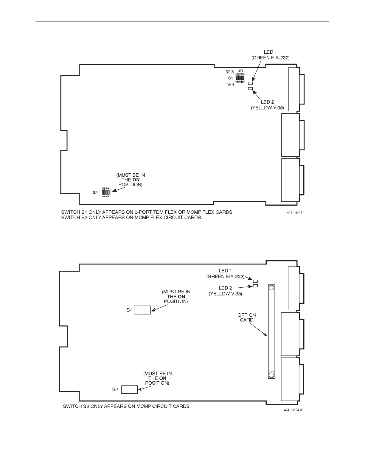
The 6-port Model 3610 TDM/Flex or MCMP/Flex has
two switches with hardware straps (refer to Figure 2-1).
• Switch S1 is for configuring a 6-port TDM/Flex or
MCMP/Flex for EIA-232 or V.35 interface
compatibility when the DSU’s firmware version is
less than 6.3x; all ports are configured for either
EIA-232 or V.35 operation. You can only use a
6-port TDM/Flex or MCMP/Flex with a DSU that
has a firmware version of less than 6.3x.
S1 is ignored if the DSU’s firmware version is 6.3 x
or greater; the 2-port TDM/Flex or MCMP/Flex
does not have S1.
• Switch S2 is only located on an MCMP/Flex; these
straps must not be changed.
For the TDM/DSD and MCMP/DSD with selectable
V.35 or EIA-232 interface compatibility on all ports via an
option card, there are two hardware straps or switches that
are for factory testing only. These two straps or switches
must not be changed. They should remain in the
positions shown in Figure 2-2.
Most straps for the TDM or MCMP are set as
configuration options. For additional DSU hardware strap
information, refer to the COMSPHERE 3600 Series Data
Units, Models 3610 and 3611, User’s Guide.
2-2 March 1999 3610-A2-GB41-60
Page 25
Model 3610 Installation
Figure 2-1. Model 3610 TDM/Flex or MCMP/Flex Switch Locations
Figure 2-2. Model 3610 TDM/DSD or MCMP/DSD Circuit Card Switch Locations
2-33610-A2-GB41-60 March 1999
Page 26
COMSPHERE 3600 Series Data Service Units
Changing Hardware Settings
If you have a new TDM/Flex or MCMP/Flex or if you
ordered a Flex field installation upgrade for a DSU having
firmware version 6.3x or greater, you do not change
hardware straps; you set each port to operate
independently of the others via the DCP, an async
terminal, or an NMS.
If you ordered the 6-port TDM/Flex or MCMP/Flex
field installation upgrade for a DSU having a firmware
version less than 6.3x, use the S1 switch to change the
TDM or MCMP port interface operation – EIA-232 or
V.35.
If you have a TDM/DSD or MCMP/DSD, use the
option card to change the TDM or MCMP port interface
operation – EIA-232 or V.35.
Follow this procedure to open the DSU and separate it
from the TDM or MCMP (refer to Figures 2-3 and 2-4).
Select the appropriate procedure based upon the type of
TDM or MCMP you have – either the switch (Flex) or
option card (DSD).
NOTE
If the unit has already been
installed, make sure that the unit
is disconnected from its power
source before changing the Flex
interface switch position.
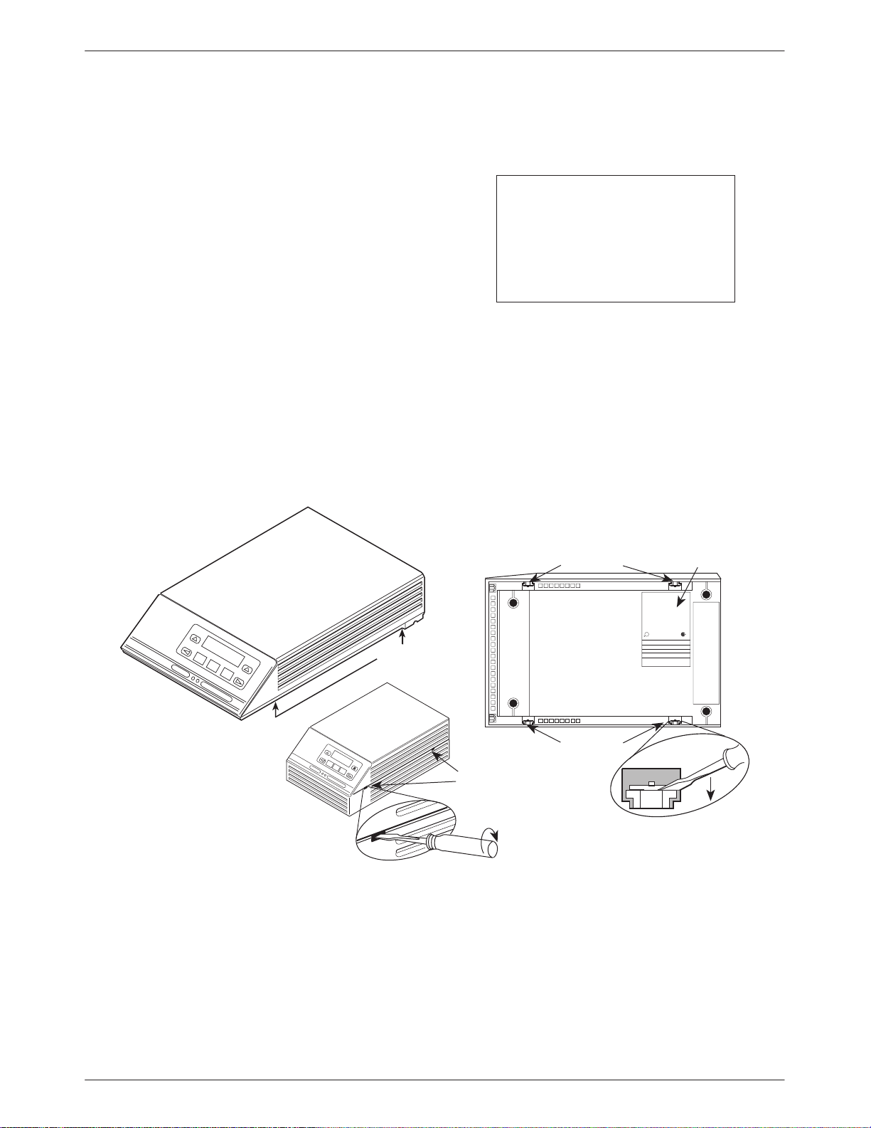
" Procedure
1. With the unit upside down, use a small flat-head
screwdriver to release the four snap tabs holding
the base in place (refer to Figure 2-3).
2. Turn the unit over while being careful not to allow
any cable to be pulled free of the connectors.
COMSPHERE 3610
COMSPHERE 3610
WITH TDM/FLEX
OR MCMP/FLEX
SNAP T ABS
SNAP T ABS
Figure 2-3. Opening the DSU
SNAP T AB
SNAP T AB
NUMBER
PEC
MFG DATE
MODEL
SER.NO
NO.
COMM CODE
MADE IN USA
U
L
R
THIS DIGITAL APPARATUS DOES NOT EXCEED THE CLASS A LIMITS FOR RADIO NOISE
EMISSIONS FROM DIGITAL APPARATUS SET OUT IN THE RADIO INTERFERENCE
REGUAALTIONS OF THE CANADIAN DEPARTMENT OF COMMUNICATIONS
FOR USE WITH A CERTIFIED CLASS 2 POWER SUPPLY FOUR UTILISER AVEC LINE
ALIMENTATION CERTIFEE
EN CLASSE 2.
THIS DEVICE COM;OIES WITH PART 15 OF THE FCC RULES OPERATION IS SUBJECT TO
THE FOLLOWING TWO CONDITIONS (1) THIS DEVICE MAY NOT CAUSE HARMFUL
INTERFERENCE AND (2) THIS DEVICE MUST ACCEPT ANY INTERFERENCE RECEIVED
INCLUDING INTERFERENCE THAT MAY CAUSE UNDESIRED OPERATION.
FCC ID: NOT APPLICABLE
496-14518a-01
SERIAL
R
2-4 March 1999 3610-A2-GB41-60
Page 27
Model 3610 Installation
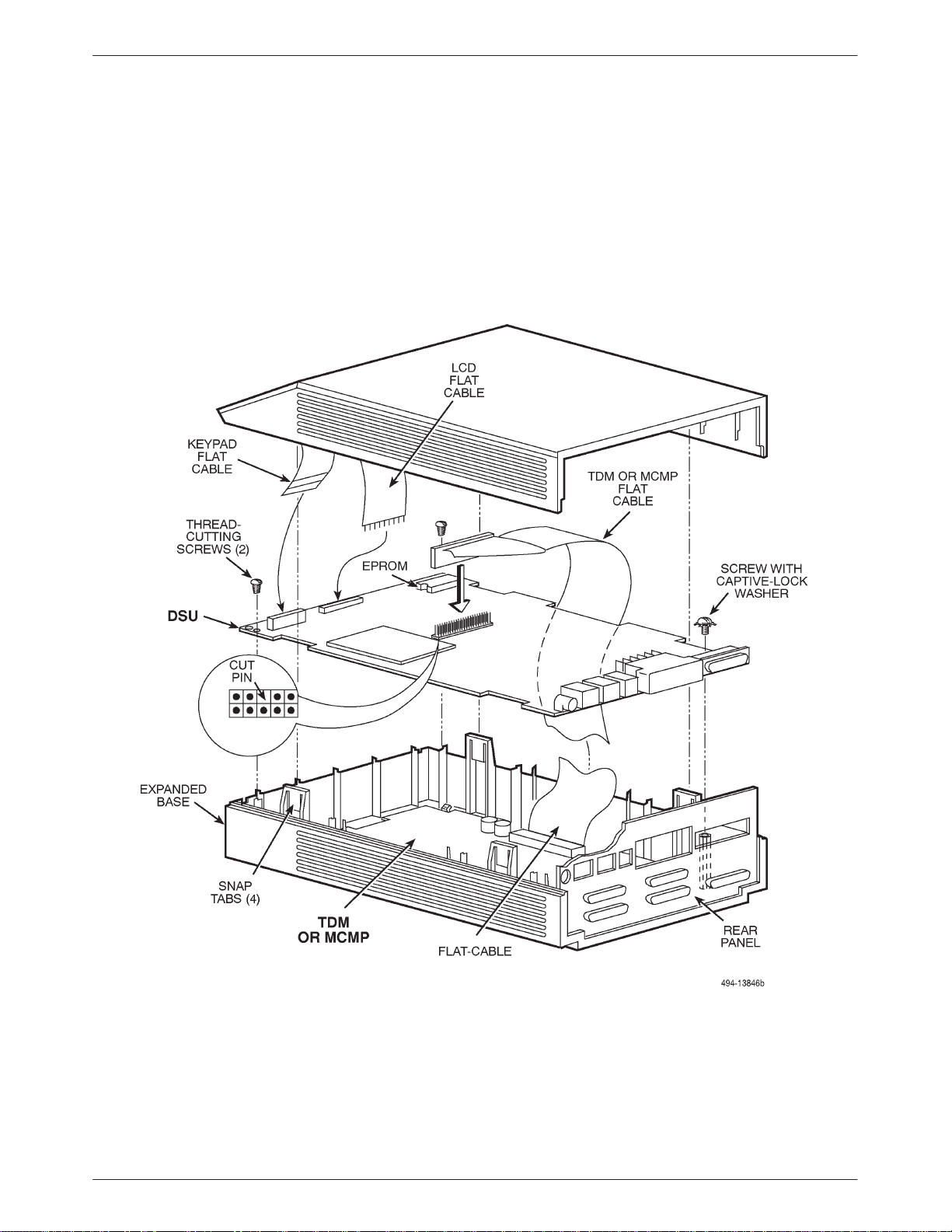
3. Disconnect the keypad flat cable from the DSU
circuit card by squeezing the latches on each side
of the cable and gently pulling up (refer to
Figure 2-4).
4. Disconnect the LCD flat cable by gently working
the cable, not the connector, free of its connector.
Be careful not to bend any of the cable pins.
5. Disconnect the TDM/MCMP flat cable.
6. Unscrew the three screws that hold the DSU
circuit card in place.
7. Remove the DSU from the base. Carefully lift the
DSU up until its connectors are free of the rear
panel. Set the DSU on a clean ESD (anti-static)
workpad.
Figure 2-4. Assembling/Disassembling the TDM or MCMP
2-53610-A2-GB41-60 March 1999
Page 28
COMSPHERE 3600 Series Data Service Units
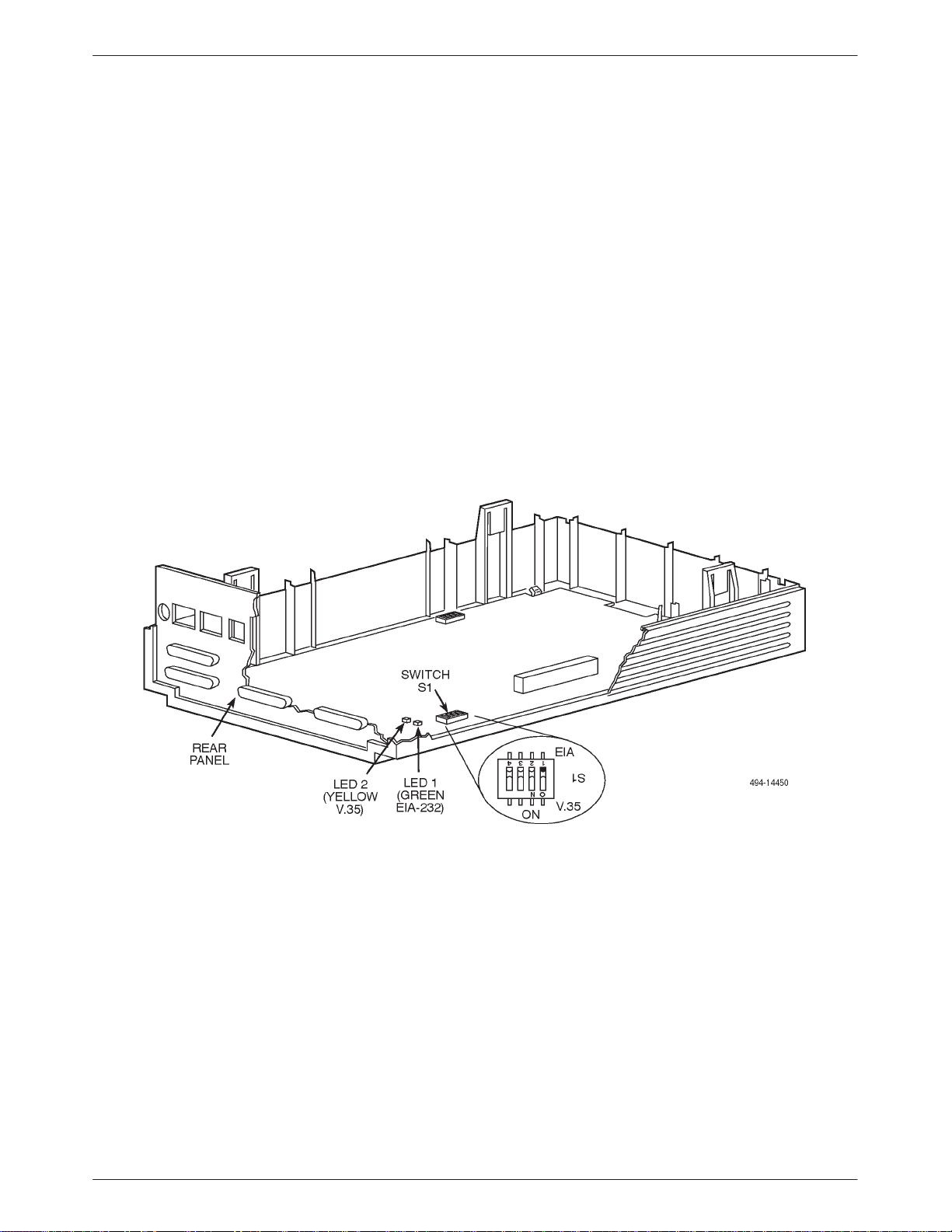
Changing the Flex Interface Switch
The TDM or MCMP field installation upgrade is
shipped from the factory with the switch position set to
EIA-232. The following procedure tells you how to
change this setting to V.35 or back to EIA-232.
" Procedure
1. Determine whether the port interfaces will be
strapped for EIA-232 or V.35.
2. Locate interface Switch S1 on the TDM/Flex or
MCMP/Flex circuit card (Figure 2-5).
If you have the 6-port version of the TDM/Flex or
MCMP/Flex, Switch S1 has four straps, but only
Strap 1 is used. (S1 is not installed on 2-port
versions of the TDM/Flex or MCMP/Flex.)
3. Insert a small pointed tool into position 1 of
Switch S1, and carefully flip the switch in the
direction of the circuit card label identifying the
setting. T o select EIA, push switch to EIA (Off)
direction. T o select V.35, push switch to V.35
(ON) direction.
4. Reinstall the DSU circuit card, securing it to the
base with the three screws (refer to Figure 2-4).
5. Reconnect the LCD, keypad, and TDM/MCMP
flat cables.
6. Replace the cover over the expanded base,
carefully aligning the rear panel and four snap tabs
over their corresponding slots.
7. Press the cover and base together until all four
tabs snap into place.
Figure 2-5. Changing TDM/Flex or MCMP/Flex Interface Compatibility
2-6 March 1999 3610-A2-GB41-60
Page 29
Model 3610 Installation
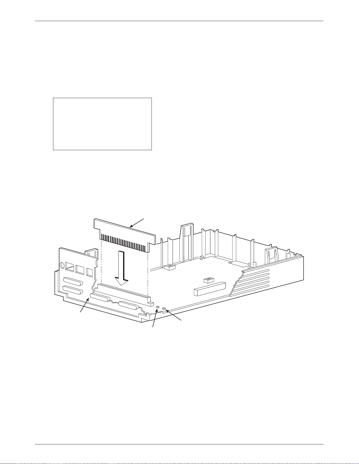
Changing the DSD Option Card
The TDM/DSD or MCMP/DSD is shipped from the
factory with the option card set to EIA-232. The following
procedure tells you how to change this setting to V.35 or
back to EIA-232.
NOTE
If the unit has already been
installed, make sure that the unit
is disconnected from its power
source before changing the
option card.
" Procedure
1. Gently work the option card free of its connector
(refer to Figure 2-6).
OPTION
CARD
THIS SIDE FACES REAR FOR V .35
2. Turn the card around, and re-insert the option card
so that from the rear, the option card reads THIS
SIDE F ACES REAR FOR V.35.
3. Reinstall the DSU circuit card, securing it to the
base with the three screws (refer to Figure 2-4).
4. Reconnect the LCD, keypad, and TDM/MCMP
flat cables. For the TDM/MCMP flat cable, make
sure the flat-cable ferrite choke is properly
positioned on the edge between the DSU and the
TDM/MCMP circuit card.
5. Replace the cover over the expanded base,
carefully aligning the rear panel and four snap tabs
over their corresponding slots.
6. Press the cover and base together until all four
tabs snap into place.
REAR
PANEL
LED 2
(YELLOW
V.35)
LED 1
(GREEN
EIA-232)
Figure 2-6. Changing TDM/DSD or MCMP/DSD Interface Compatibility
496-13845-02
2-73610-A2-GB41-60 March 1999
Page 30

COMSPHERE 3600 Series Data Service Units
Electrical Connection
CAUTION
The power cord with ac
transformer contains a 3-wire
grounding-type plug which
has a grounding pin. This is a
safety feature. Grounding of
the unit is vital to ensure safe
operation. Do not defeat the
purpose of the grounding
plug by modifying it or by
using an adapter.
Prior to installation, use an
outlet tester or voltmeter to
check the ac receptacle for
earth ground. If the power
source does not provide a
ground connection, consult
an electrician to determine
another method of grounding
the unit before proceeding
with the installation.
CAUTION
Only use the power transformer
designed for the Model 3610
DSU. Using other transformers
may result in personal injury or
damage to the equipment.
4. Reinstall the factory configuration options; use the
FacT configuration for a tributary or FacC for a
control.
5. Make any desired configuration changes in the
DSU, Diag, DBM, Gen, Bckup, MUX, PrtSp, and
LPDA-2 option sets.
For information on the TDM, MCMP, or digital
bridge option sets, refer to the Unit Configuration
section of this guide and the COMSPHERE
3600 Series Data Service Units, Models 3610 and
361 1, User’s Guide or the COMSPHERE 3600
Series Data Service Units, Models 3610 and 361 1,
Operator’s Guide.
T o power up the DSU:
" Procedure
1. Use a non-switched, 3-prong grounded ac wall
outlet capable of supplying the specified voltage
and current.
2. Label the circuit breaker that protects the wall
outlet and be sure it is set to ON.
3. At the rear of the DSU (Figure 2-7), insert the
small end of the power cable into the power
receptacle.
If you have a table-top ac transformer, connect the
3-prong plug to the ac outlet. If you have a
wall-mount ac transformer, connect the
ac transformer to the ac outlet.
The unit performs a power-up routine.
Power-Up Routine
When power is applied, the DSU:
• Determines what options are installed (DBM or
MUX – the TDM or MCMP).
• Runs a Device T est on the unit and each of the
installed options.
During the tests, all indicators on the DCP light
briefly and the message Power-Up Tests appears
on the liquid crystal display (LCD).
• Displays the results of each test momentarily as
Pass, Fail, or Abrt. These tests take about
20 seconds to complete. Abrt indicates that the
Device T est was aborted because a network
loopback was in progress during the power-up
procedure.
When a TDM or MCMP is installed, MUX is
displayed as Pass or Fail.
2-8 March 1999 3610-A2-GB41-60
Page 31

WITHOUT TDM or MCMP OPTION
FRONT BEZEL
Model 3610 Installation
COMSPHERE 3610
FRONT BEZEL
AC TRANSFORMER
WALL-MOUNT
SNAP T ABS
LOW VOLTAGE
AC POWER IN
(4)
INTERFACE
DDS
INTERFACE
DBM
WALL-MOUNT
AC TRANSFORMER
AC TRANSFORMER
WITH TDM or MCMP OPTION
V.35 INTERFACE
(PORT 1)
NETWORK
DIAGNOSTIC
INTERFACE
EIA-232-D/V.24
INTERFACE
(PORT 1)
PORT 3
PORT 4
TABLE-TOP
PORT 2
COMSPHERE 3610
PORT 5
PORT 6
TABLE-T OP
AC TRANSFORMER
WITH TDM or MCMP OPTION
Figure 2-7. Model 3610 DSU with TDM or MCMP
NOTE:
ADDITIONAL EIA-232
INTERFACES PORT
NUMBERS 2 – 6.
496-13015-05
2-93610-A2-GB41-60 March 1999
Page 32

COMSPHERE 3600 Series Data Service Units
If the DSU, DBM, TDM or MCMP (MUX) fails the
power-up test:
" Procedure
1. Reinstall the factory configuration options; use the
FacT configuration for a tributary or FacC for a
control.
2. Confirm the installed hardware options (DBM,
TDM, or MCMP).
3. Re-execute the Device Test. (Press the
return to the top-level menu, then select Local
Test DSU Devic). If the test passes,
continue with the installation.
Since the DSU is not connected to the network,
the red Alrm indicator is lit, and the LCD displays
No Signal, indicating a facility alarm. The LCD
displays health and status information.
The red Alarm LED lights when there is no DDS
signal.
NOTE
If the test fails again, call your
service representative to return
the DSU-TDM or DSU-MCMP
unit; refer to Chapter 1 in the
COMSPHERE 3600 Series Data
Service Units, Models 3610 and
3611, Time Division Multiplexer,
Multichannel Multipoint, and
Digital Bridge Options, User’s
or the
Guide
3600 Series Data Service Units,
Models 3610 and 3611,
Operator’s Guide
COMSPHERE
.
key to
Network Diagnostic
Connection
The DSU may be set up for a diagnostic interface with
the NMS using a 3600 Hubbing Device. For further
information about installing a hubbing device or
connecting to a router or async terminal, refer to the
COMSPHERE 3600 Series Data Service Units, Models
3610 and 3611, User’s Guide, or the COMSPHERE 3600
Series Data Service Units, Models 3610 and 361 1,
Operator’s Guide.
Software Configuration
A default software configuration is loaded in the DSU
at the factory. If the TDM is installed, the Model 3610
DSU is configured as a tributary with TDM mode enabled
and Port 1 set to operate at 9.6 kbps. If the MCMP is
installed, the DSU is configured as a tributary with
MCMP mode enabled and Port 1 set to operate at
9.6 kbps.
Software configurations can be changed from the DCP,
an async terminal, or from an NMS that supports this
feature.
From the DCP and Async Terminal
T o change configuration options from the DCP, use the
selection sequence from the top-level menu. The Options
(Opts) branch is used to change configuration options.
You can also change configuration options using an
async terminal. Once an async terminal session is active,
changing configuration options follows the same steps as
as the DCP.
2-10 March 1999 3610-A2-GB41-60
Page 33

Model 3610 Installation
T o change configuration options of the Model 3610
DSU from the DCP or the Model 3610 from an async
terminal, select the Local branch, then the Configuration
(Confg) branch. (If not displayed, press the
Confg is displayed, then press the function key below the
selection.) Select Opts (for Configuration Options), then
Load.
For additional information about changing
configuration options from the DCP or async terminal or
for a listing of messages received during installation, refer
to the COMSPHERE 3600 Series Data Service Units,
Models 3610 and 3611, Time Division Multiplexer,
Multichannel Multipoint, and Digital Bridge Options,
User’s Guide, Chapter 3, or order the COMSPHERE 3600
Series Data Service Units, Models 3610 and 361 1,
Operator’s Guide and refer to Chapter 6 and Appendix E.
key until
From the NMS
Software configuration options for a Model 3610 with
a TDM or MCMP can also be set from a 6800 Series
NMS using the Change commands. These commands
include the following:
• cho followed by the DSU’s network address allows
you to change the DSU, Diagnostic (DSU, DBM,
and General), General, MUX Setup and Port, Port
Speed, and LPDA configuration option sets.
• cho followed by the DBM’s network address allows
you to change the DBM, Backup, Diagnostic (DSU,
DBM, and General), General, MUX Setup and Port,
and Port Speed configuration option sets.
• cha followed by the DSU’s serial number allows
you to change the tributary DSU’s network address.
For the 6700 Series NMS, configuration options are
menu-driven. Select Config→Network→Devices→ the
appropriate submenu selection.
Tributary 3610 DSUs with TDM or MCMP can be
configured from an NMS provided the Position
configuration option (Diagnostic General) is set to Trib
from the DCP and the DSU is connected to a control DSU
that is connected to the NMS.
The COMSPHERE 6700 or 6800 Series NMS, which
uses the Advanced Diagnostic protocol (ADp), fully
supports configuration of the DSUs with TDM and
multipoint dial backup or MCMP. Refer to the NMS
documentation as needed.
Configuration of the DSUs from an NMS using either
the DPII or DMC protocol is subject to the same
limitations identified in the COMSPHERE 3600 Series
Data Service Units, Models 3610 and 3611, User’s Guide
or the COMSPHERE 3600 Series Data Service Units,
Models 3610 and 3611, Operator’s Guide.
Network and LADS
Connections
For connection to the DDS, switched 56 kbps, and
public switched telephone or dial networks, or to a local
area data set (also called a limited-distance modem), refer
to the COMSPHERE 3600 Series Data Service Units,
Models 3610 and 3611, User’s Guide, or the
COMSPHERE 3600 Series Data Service Units,
Models 3610 and 3611, Operator’s Guide.
DSU DTE Connection
Make the DTE connection as described in the
COMSPHERE 3600 Series Data Service Units, Models
3610 and 3611, User’s Guide.
In a TDM or MCMP application, only DSU Port 1 is
capable of interfacing to an EIA-232 connector or a
V.35 connector. In a DSD application, an option card
allows all ports to operate as either EIA-232 or
V.35 interfaces. In a Flex application where the DSU
firmware version is less than 6.3x, a Flex interface switch
allows all ports to operate as either EIA-232 or an V.35
interface.
Ports 2 through 6 have only EIA-232 connectors. If
speeds higher than 19.2 kbps are selected for these ports,
an Paradyne special cable provides an interface between
the TDM’s or MCMP’s D-type connector and the DTE
cable’s V.35 connector.
2-113610-A2-GB41-60 March 1999
Page 34

COMSPHERE 3600 Series Data Service Units
Verification Testing
Perform verification testing after any installation. After
installing and configuring a network, including control
and tributary DSUs, the DDS network and, if appropriate,
DBMs and their dial connections, perform the following
series of tests from the control DSU (using the DCP, an
async terminal, or an NMS) to verify network operation.
" Procedure
1. Request a device Identity (ID from the Status
branch) report from each tributary to ensure that
the DSU is addressed properly.
2. Perform a Digital Test (on the DDS circuit) to
ensure that the network is functioning. Refer to the
Digital Test section of Chapter 5.
For a DSU configured for TDM mode, perform a
Digital T est on each active port.
For a DSU configured for MCMP mode, perform a
Digital T est on each tributary DSU on the
aggregate channel.
For a digital-sharing group, perform a Digital Test
on the lower-numbered port in the digital-sharing
group only.
NOTE
A control DSU can originate a
Digital Test in a point-to-point or
multipoint network. A tributary
DSU can originate a Digital Test
in a point-to-point network only,
provided the configuration
option Respond to Remote
Digital Loopback
(RespondRDL) is enabled in
the control.
For a DSU equipped with a DBM:
" Procedure
1. Select the Dial command from Bckup while in
Idle Mode to establish a dial call to the tributary to
test for dial tone, and verify that the DSU can
initiate and receive calls.
2. Select the →Dial command to switch the data to
the PSTN or switched 56 kbps circuit (enter Dial
Backup mode) to ensure that both DSUs have
been configured correctly.
3. Perform a Digital Test on both the DBM and the
PSTN or switched 56 kbps circuit.
For a DSU equipped with both DBM and TDM or
MCMP, perform a Digital Test on each of the
TDM or MCMP ports in Dial Backup mode on the
PSTN or switched 56 kbps circuit.
4. Drop the backup.
For a DSU equipped with MCMP:
" Procedure
1. From the control DSU, go to the Control (Ctrl)
branch, select LEDs, and then select Aggregate
(Aggr) to monitor the aggregate 56 kbps digital
signal.
2. Go to the Configuration (Confg) branch and select
Poll List (PList) from the menu.
3. Acquire the poll list (Acq). This command starts
the initialization process.
4. Verify that each tributary DSU with MCMP has
been acquired by displaying (Displ) the MCMP
poll list.
If the DSU’s address does not appear on the list,
verify that the missing tributary DSU is equipped
with the MCMP option and configured for MCMP
mode.
After the poll list has been acquired, the LSD and
RXD light-emitting diodes (LEDs) should be
flashing without a pause at the control DSU’s
DCP. Any pause indicates that a tributary on the
poll list is not responding.
5. From the tributary DSU, if a new drop is being
added to an existing MCMP circuit, select Add
from the Poll List menu. This places the tributary
DSU on the control DSU’s poll list.
6. After the tributary DSUs have been added to the
control DSU’s poll list, go back to the Control
(Ctrl) branch, select LEDs, and reassign the
LEDs from the aggregate data path (Aggr) to one
of the DSU ports (Prt1, Prt2, Prt3, etc.).
MCMP capability is now functional, with all tributary
DSUs on the control DSU’s MCMP poll list. At this point,
DSU ports can be assigned to MCMP channels through
the Port Speed (PrtSp) selection from the Configuration
Options (Opts) submenu.
2-12 March 1999 3610-A2-GB41-60
Page 35

Model 3610 Installation
Adding a TDM/Flex or
MCMP/Flex to an Installed
Model 3610 DSU
This section describes the procedure for adding a
TDM/Flex or MCMP/Flex upgrade for the Model 3610
DSU.
The time division multiplexer (TDM/Flex) or
multichannel multipoint (MCMP/Flex) upgrade for the
Model 3610 (standalone) DSU includes a circuit card that
rests in an expanded base with an expanded rear panel.
If this upgrade is to be installed on a DSU with
firmware version 6.3x or greater, each port (Port 1 or
Port 2 for the 2-port version, or Ports 1 through 6 for the
6-port version) can be configured independently to
operate as an EIA-232 or V.35 interface via the DCP, an
async terminal, or a 6700 or 6800 Series NMS.
If the upgrade is to be installed on a DSU with
firmware version less than 6.3x, Switch S1 must be
changed to switch all ports from EIA-232 to V.35
operation. Only the 6-port TDM/Flex or MCMP/Flex can
be used with DSUs with firmware version (DSU SW ver:)
less than 6.3x; the 2-port TDM/Flex or MCMP/Flex is not
supported.
If installing a 6-port TDM/Flex or MCMP/Flex and
your DSU has a wall-mount ac transformer, a table-top
transformer must be ordered (part number
654-0099-0131).
If connecting a port to data communications equipment
(DCE), a crossover cable is required (feature number
3211-178F for a V.35 Crossover Cable or feature number
4951-035F for an EIA-232 Crossover Cable). If using
V.35 operation, a V.35 adapter (feature number
3000-F1-510) is required for Ports 2 through 6; the V.35
connector on the DSU is used for Port 1.
Before disconnecting the DSU:
" Procedure
1. Copy the applicable Configuration Worksheet
from Appendix B.
2. Access Stat (Status branch) and ID (Identity
subbranch).
3. Record the unit’s serial number at the top of
Page 1 of the Configuration Worksheet.
4. Access Confg (Configuration branch).
5. Record the configuration option settings for each
option set (DSU, Diag, etc.).
If a DBM is installed, continue with:
1. Record all Backup Directory entries.
2. Record the unit’s local telephone number (Phone).
For instructions and handling precautions for opening
the DSU, refer to the Hardware Straps and Changing the
Hardware Settings sections of this chapter.
2-133610-A2-GB41-60 March 1999
Page 36

COMSPHERE 3600 Series Data Service Units
Getting Started
As you follow these steps, refer to Figure 2-8.
" Procedure
1. Unplug the table-top ac transformer from the ac
outlet, then disconnect the power cord from the
DSU’s rear panel (labeled POWER).
2. Disconnect the DDS interface cable (labeled
LINE) from the DSU.
3. Disconnect the DBM and NMS interface cables
(labeled BACKUP and CC/DC, respectively), if
installed.
4. Disconnect the EIA-232-D/V.24 or V.35 interface
cable from the DSU.
5. If a TDM or MCMP is being replaced, disconnect
the additional port interface cable(s), as well.
NOTE
If a TDM or MCMP is being
replaced, the unit does not have
to be turned upside down to
open the case.
6. With the unit upside down, use a small flat-head
screwdriver to release the four snap tabs holding
the base in place (refer to Figure 2-3).
7. Turn the unit over while being careful not to allow
any cable to be pulled free of the connectors.
Figure 2-8. Disconnecting the DSU
2-14 March 1999 3610-A2-GB41-60
Page 37

Model 3610 Installation
Removing the DSU from Its Base
Refer to Figure 2-4 as you follow these steps. If
replacing a TDM or MCMP, refer to this figure as you
remove the current TDM or MCMP.
" Procedure
1. Disconnect the keypad flat cable from the DSU by
squeezing the small black latches on each side of
the cable and carefully lifting the cable up and out
of the connection.
2. Disconnect the LCD flat cable from the DSU
circuit card. Gently work the cable (not the
connector) out from the connector . Be careful not
to bend any of the cable pins.
3. If a TDM or MCMP, is being replaced, disconnect
the TDM or MCMP flat cable’s pre-folded
40-position header from the DSU, and fold the
TDM or MCMP flat cable out over the side of the
expanded base. Remove the two thread-cutting
screws at the front corners and the screw with
captive-lock washer at the rear corner of the DSU.
4. Remove the DSU from the existing base.
Carefully lift the DSU up until its connectors are
free of the rear panel. Set the DSU on a clean ESD
(anti-static) workpad.
5. Write the serial number from the existing base
onto the new TDM or MCMP expanded base
using indelible ink (see Figure 2-3). Discard the
existing base and rear panel.
Installing a TDM/Flex
or MCMP/Flex
T o change the Flex interface S1 switch, refer to the
Changing the Flex Interface Switch section of this chapter.
T o complete the TDM/Flex or MCMP/Flex installation,
refer to Figure 2-4 while following this procedure.
" Procedure
1. Fold the TDM or MCMP flat cable out over the
side of the new expanded base.
2. Position the DSU over the new expanded base.
3. Secure the DSU to the expanded base using the
two #4 thread-cutting screws at the front corners,
and the #4 screw with captive-lock washer at the
rear corner (make sure this screw is tightened).
4. Connect the TDM or MCMP flat cable’s
pre-folded 40-position header to the DSU. Make
sure the pins are correctly aligned with the
connector (one pin hole on the connector is
blocked).
5. Reconnect the keypad flat cable by inserting the
cable into its connector as far as it will go. Then,
push down on the tiny latching mechanism.
6. Being careful not to bend the pins, align the LCD
flat cable to its connector. Then gently push the
cable pins back into place.
2-153610-A2-GB41-60 March 1999
Page 38

COMSPHERE 3600 Series Data Service Units
Reassembling the Unit
Refer to Figure 2-4 as you close the unit and Figure 2-8
to reconnect cables.
" Procedure
1. Align the cover over the expanded base and rear
panel. Make sure the four snap tabs are over their
corresponding slots (two in front and two in back).
2. Apply pressure at the four snap tab connecting
points, pressing together until all four tabs snap
securely into their slots.
3. Reconnect the power cord to the DSU (labeled
POWER), referring back to Figure 2-8.
4. Plug the 3-prong plug of the table-top
ac transformer into the ac outlet. If installing a
6-port TDM/Flex or MCMP/Flex and the
DSU has a wall-mount ac transformer, the
wall-mount ac transformer must be replaced with
a table-top ac transformer. If installing a 2-port
TDM/Flex or MCMP/Flex on a unit having a
wall-mount ac transformer, plug the
ac transformer into the ac outlet.
On power-up, the DSU determines what options
(TDM or MCMP) are installed. Refer to
Power-Up Routine in this chapter.
5. Verify operation; refer to Verification Testing
section in this chapter.
6. If the keypad and/or LCD functions fail, check the
Keypad and LCD flat cables for proper
installation. Perform the Device T est again.
If the Device T est fails again, call your service
representative for assistance.
2-16 March 1999 3610-A2-GB41-60
Page 39

Model 3611 Installation
Overview 3-1. . . . . . . . . . . . . . . . . . . . . . . . . . . . . . . . . . . . . . . . . . . . . . . . . . . . . . . . . . . . . . . . . . . . . . . . . .
Non-Modular DSU with a TDM or MCMP 3-2. . . . . . . . . . . . . . . . . . . . . . . . . . . . . . . . . . . . . . . . . . . .
Modular DSU with a TDM or MCMP 3-2. . . . . . . . . . . . . . . . . . . . . . . . . . . . . . . . . . . . . . . . . . . . . . . . .
DBM-Vs/DBM-Ss/DBM-Ds 3-2. . . . . . . . . . . . . . . . . . . . . . . . . . . . . . . . . . . . . . . . . . . . . . . . . . . . . . . .
Hardware Straps 3-3. . . . . . . . . . . . . . . . . . . . . . . . . . . . . . . . . . . . . . . . . . . . . . . . . . . . . . . . . . . . . . . . . . . .
Software Configuration 3-4. . . . . . . . . . . . . . . . . . . . . . . . . . . . . . . . . . . . . . . . . . . . . . . . . . . . . . . . . . . . . . .
From the SDCP 3-4. . . . . . . . . . . . . . . . . . . . . . . . . . . . . . . . . . . . . . . . . . . . . . . . . . . . . . . . . . . . . . . . . .
From the NMS 3-4. . . . . . . . . . . . . . . . . . . . . . . . . . . . . . . . . . . . . . . . . . . . . . . . . . . . . . . . . . . . . . . . . . .
Verification Testing 3-5. . . . . . . . . . . . . . . . . . . . . . . . . . . . . . . . . . . . . . . . . . . . . . . . . . . . . . . . . . . . . . . . . .
Adding a TDM or MCMP to an Installed Model 3611 DSU 3-6. . . . . . . . . . . . . . . . . . . . . . . . . . . . . . . . . .
Installing a Non-Modular TDM or MCMP 3-7. . . . . . . . . . . . . . . . . . . . . . . . . . . . . . . . . . . . . . . . . . . . .
Power-Up Routine 3-8. . . . . . . . . . . . . . . . . . . . . . . . . . . . . . . . . . . . . . . . . . . . . . . . . . . . . . . . . . . . . . . .
Installing a Modular TDM or MCMP 3-10. . . . . . . . . . . . . . . . . . . . . . . . . . . . . . . . . . . . . . . . . . . . . . . . .
Removing a TDM or MCMP from an Installed Model 3611 DSU 3-13. . . . . . . . . . . . . . . . . . . . . . . . . . . . .
3
Overview
The Model 3611 DSU-TDM or DSU-MCMP is
designed for installation in a COMSPHERE 3000 Series
Carrier, which supplies operating power and provides
interfaces for connecting to the DDS and, if required,
analog networks. Up to 16 DSUs can be installed in a
COMSPHERE 3000 Series Carrier.
A Model 3611 DSU (modular or non-modular) is
delivered with default strap settings and factory-installed
software options. The DSU is ready to connect to the
network and is configured as a control DSU for operation
at 9.6 kbps on a point-to-point circuit, with diagnostic
protocol set to ADp. When a TDM or MCMP is installed,
Port 1 of the DSU is configured to operate at 9.6 kbps
with the TDM or MCMP capability enabled; all other
ports are disabled.
NOTE
In this guide, Model 3611 refers
to either the modular or the
non-modular DSU-TDM or
DSU-MCMP, unless otherwise
specified.
A shared diagnostic control panel (SDCP), installed in
the carrier, is required for installation and maintenance of
the Model 3611 DSU-TDM or DSU-MCMP.
Installation of the DSU-TDM or DSU-MCMP and
carrier-related equipment consists of the following
procedures, which should be performed in the order listed.
• Changing hardware straps (if necessary)
• Physical installation of the DSU-TDM or
DSU-MCMP
• Network diagnostic connection
• Software configuration
• DDS network (or LADS) connection
• PSTN or switched 56 kbps network connection
(if a DBM is installed)
• DSU DTE connection
• Operation verification
This chapter tells you how to perform the procedures.
For electrical connection, network diagnostic connection,
PSTN and switched 56 kbps network connection, DDS
network or LADS connection, and DSU DTE connection
information, refer to the COMSPHERE 3000 Series
Carrier, Installation Manual.
3-13610-A2-GB41-60 March 1999
Page 40

COMSPHERE 3600 Series Data Service Units
Non-Modular DSU with a TDM or MCMP
The non-modular Model 3611 DSU-TDM or
DSU-MCMP has connectors mounted directly onto the
circuit cards. With this type of unit, the DTE cables must
be disconnected before the unit can be removed from the
carrier.
A 60-pin high-density connector is mounted onto the
TDM or MCMP circuit card. This connector requires
either a TDM Interface Cable (feature number
3600-F2-500, part number 035-0101-0631) or a Digital
Bridge Interface Cable (feature number 3600-F2-501, part
number 035-0102-0631), depending upon the application.
These cables must be ordered separately.
These cables provide fan-out cabling to five individual
EIA-232 25-pin connectors. Each cable is six feet long
and connected to the unit’s dedicated DBM-Vs, DBM-Ss,
or DBM-Ds. The fan-out section is one foot long.
Appendix C shows each cable and its pin assignments,
as well as the TDM’s or MCMP’s 60-pin high-density
connector. To order cables, refer to Equipment Lists,
Appendix L, of the COMSPHERE 3600 Series Data
Service Units, Models 3610 and 361 1, Operator’s Guide.
In addition to the six ports on the 6-port connector
module, a 26-pin high-density D-type connector is located
at the top of the connector module to provide a V.35
interface for either Port 1 or an aggregate data path. T o
use the V.35 interface, the 6-port V.35 Interconnect Cable
(feature number 3600-F3-500, part number
035-0174-0031) is required. The cable provides an
interface between the high-density D-type connector and a
DTE cable’s V.35 connector .
Appendix C shows the 6-port connector module and
provides the port pin assignments. Cables must be ordered
separately .
DBM-Vs/DBM-Ss/DBM-Ds
DBM-Vs, DBM-Ss, and DBM-Ds are dial backup units
that are used for multipoint dial backup. Each DBM-V,
DBM-S, or DBM-D occupies a slot in the COMSPHERE
3000 Series Carrier, and is connected to a TDM or MCMP
circuit card through cables. Up to five DBM-Vs, DBM-Ss,
or DBM-Ds can be connected to a DSU-TDM or
DSU-MCMP. The TDM or MCMP option is configured to
operate as a digital bridge; the digital bridge and its
DBMs are dedicated to a single DSU within the carrier.
Modular DSU with a TDM or MCMP
The modular DSU-TDM or DSU-MCMP has “gold
finger” contacts for connectors, which plug into a 6-port
connector module (delivered with the unit) that is
mounted onto the rear of the carrier. With this type of unit,
the DTE cables do not have to be disconnected before
removing the unit from the carrier.
Each port on the 6-port connector module is a 25-pin
connector that provides the EIA-232 DTE interface. All
port connectors are individual with this type of unit, and a
separate crossover cable is required for each connector
that is attached to a DBM-V, DBM-S, or DBM-D.
T ypical configurations for various applications can be
found in the Digital Bridge/DBM-V/DBM-S/DBM-D
Interface section of Chapter 4. Various configurations for
digital bridge and DBM-V, DBM-S, and DBM-D
applications are shown in Appendix D. Installation
procedures for connecting DBMs are included in the
Adding the TDM or MCMP Option to an Installed Model
3611 DSU section in this chapter.
3-2 March 1999 3610-A2-GB41-60
Page 41

Model 3611 Installation
Hardware Straps
HANDLING PRECAUTIONS
FOR
ST ATIC-SENSITIVE DEVICES
This product is designed to protect
sensitive components from damage
due to electrostatic discharge (ESD)
during normal operation. When
performing installation procedures,
however, take proper static control
precautions to prevent damage to
equipment. If you are not sure of the
proper static control precautions,
contact your nearest sales or service
representative.
The Model 3611 DSU has one switch and one jumper
on the circuit card that should be reset, if necessary,
before the DSU is inserted into the carrier. Refer to the
COMSPHERE 3600 Series Data Service Units,
Models 3610 and 3611, Operator’s Guide, which can be
ordered, to change the straps.
When the T est Mode Indication jumper is enabled, the
V.35 lead NN and Pin 25 on the EIA-232-D/V.24 interface
go to ON (+EIA level) condition during a T est mode. This
is the default setting on a DBM-V, DBM-S, or DBM-D.
When disabled, the leads do not change to indicate a T est
mode. The indicator lead for each interface can be enabled
or disabled independently.
On the non-modular TDM or MCMP circuit card, there
are hardware (jumper) straps that are for factory testing
only (Figure 3-1). On the TDM circuit card, the jumpers
labeled P1 and P2 are set; on the MCMP circuit card,
jumpers labeled P1 through P5 are set. These straps must
not be changed. They should remain in the positions
shown in Figure 3-1.
The switches on the modular TDM or MCMP circuit
cards are shown in Figure 3-2, but they should remain in
the ON position. They are for factory test purposes only.
Most straps for the DSU-TDM or DSU-MCMP are set
as configuration options.
Figure 3-1. Non-Modular TDM/MCMP Circuit Card Switch Locations
3-33610-A2-GB41-60 March 1999
Page 42

COMSPHERE 3600 Series Data Service Units
Figure 3-2. Modular TDM/MCMP Circuit Card Switch Locations
Software Configuration
A default software configuration is loaded in the DSU
at the factory. If the TDM option is installed, the
Model 3611 DSU is configured as a control with TDM
mode enabled and Port 1 set to operate at 9.6 kbps. If the
MCMP option is installed, the DSU is configured as a
control with MCMP mode enabled and Port 1 set to
operate at 9.6 kbps.
Software configurations can be changed from the
SDCP or from an NMS that supports this feature.
From the SDCP
T o change TDM, MCMP, or digital bridge
configuration options from the SDCP, use the selection
sequence from the top-level menu. The Options (Opts)
branch is used to change configuration options.
For additional configuration option information, refer
to Unit Configuration, Chapter 4, of the COMSPHERE
3600 Series Data Service Units, Models 3610 and 361 1,
Time Division Multiplexer, Multichannel Multipoint, and
Digital Bridge Options, User’s Guide Supplement, or
Configuration Options, Chapter 6, of the COMSPHERE
3600 Series Data Service Units, Models 3610 and 361 1,
Operator’s Guide.
For a listing of SDCP messages received when a TDM
or MCMP is installed, refer to Appendix B of the
COMSPHERE 3600 Series Data Service Units,
Models 3610 and 3611, Time Division Multiplexer,
Multichannel Multipoint, and Digital Bridge Options,
User’s Guide Supplement, or Appendix C of the
COMSPHERE 3600 Series Data Service Units, Models
3610 and 3611, Operator’s Guide.
From the NMS
Software configuration options for a Model 3611 with
a TDM or MCMP can also be set from a 6800 Series
NMS using the Change commands. These commands
include the following:
• cho followed by the DSU’s network address allows
you to change the DSU, Diagnostic (DSU, DBM,
and General), General, MUX Setup and Port, Port
Speed, and LPDA configuration option sets.
• cho followed by the DBM’s network address allows
you to change the DBM, Backup, Diagnostic (DSU,
DBM, and General), General, MUX Setup and Port,
and Port Speed configuration option sets.
• cha followed by the DSU’s serial number allows
you to change the tributary DSU’s network address.
3-4 March 1999 3610-A2-GB41-60
Page 43

Model 3611 Installation
For the 6700 Series NMS, configuration options are
menu-driven. Select Config→Network→Devices→ the
appropriate submenu selection.
Tributary 3610 DSUs with TDM or MCMP can be
configured from an NMS provided the Position
configuration option (Diagnostic General) is set to Trib
from the SDCP and the DSU is connected to a control
DSU that is connected to the NMS.
The COMSPHERE 6700 or 6800 Series NMS, which
uses the Advanced Diagnostic protocol (ADp), fully
supports configuration of the DSUs with TDM and
multipoint dial backup or MCMP.
Configuration of the DSUs from an NMS using either
the DPII or DMC protocol is subject to the same
limitations identified in the COMSPHERE 3600 Series
Data Service Units, Models 3610 and 3611, User’s Guide
or the COMSPHERE 3600 Series Data Service Units,
Models 3610 and 3611, Operator’s Guide.
For more information on the matrix-coded format
and/or the NMS commands, refer to your NMS
documentation.
Verification Testing
Perform verification testing after any installation. After
installing and configuring a network, including control
and tributary DSUs, the DDS network and, if appropriate,
DBMs and their dial connections, perform the following
series of tests from the control DSU (using the SDCP or
an NMS) to verify network operation.
" Procedure
1. Request a device Identity (ID from the Status
branch) report from each tributary to ensure that
the DSU is addressed properly.
2. Perform a Digital Test (on the DDS circuit)
to ensure that the network is functioning. Refer to
the Digital Test section of chapter 5.
For a DSU configured for TDM mode, perform a
Digital T est on each active port.
For a DSU configured for MCMP mode, perform a
Digital T est on each tributary DSU on the
aggregate channel.
For a digital-sharing group, perform a Digital
T est on the lower-numbered port in the
digital-sharing group only.
NOTE
A control DSU can originate a
Digital Test in a point-to-point or
multipoint network. A tributary
DSU can originate a Digital Test
in a point-to-point network only,
provided the configuration
option Respond to Remote
Digital Loopback
(RespondRDL) is enabled in
the control.
For a DSU equipped with a DBM:
" Procedure
1. Select the Dial command to establish a dialed call
to the tributary to test for dial tone and verify that
the DSU can initiate and receive calls.
2. Select the →Dial command to switch the data to
the PSTN or switched 56 kbps circuit (enter Dial
Backup mode) to ensure that both DSUs have
been configured correctly.
3. Perform a Digital Test on both the DBM and the
PSTN or switched 56 kbps circuit.
For a DSU equipped with both DBM and TDM or
MCMP, perform a Digital Test on each of the
TDM or MCMP ports in Dial Backup mode on the
PSTN or switched 56 kbps circuit.
4. Drop the backup.
3-53610-A2-GB41-60 March 1999
Page 44

COMSPHERE 3600 Series Data Service Units
For a DSU equipped with MCMP:
" Procedure
1. From the control DSU, go to the Control (Ctrl)
branch, select LEDs, and then select Aggregate
(Aggr) to monitor the aggregate 56 kbps digital
signal.
2. Go to the Configuration (Confg) branch and select
Poll List (PList) from the menu.
3. Acquire the poll list (Acq). This command starts
the initialization process.
4. Verify that each tributary DSU with MCMP has
been acquired by displaying (Displ) the MCMP
poll list.
If the DSU’s address does not appear on the list,
verify that the missing tributary DSU is equipped
with the MCMP option and configured for MCMP
mode.
After the poll list has been acquired, the LSD and
RXD light-emitting diodes (LEDs) should be
flashing without a pause at the control DSU’s
DCP. Any pause indicates that a tributary on the
poll list is not responding.
5. From the tributary DSU, if a new drop is being
added to an existing MCMP circuit , select Add
from the Poll List menu. This places the tributary
DSU on the control DSU’s poll list.
6. After the tributary DSUs have been added to the
control DSU’s poll list, go back to the Control
(Ctrl) branch, select LEDs, and reassign the
LEDs from the aggregate data path (Aggr) to one
of the DSU ports (Prt1, Prt2, Prt3, etc.).
Adding a TDM or MCMP to an
Installed Model 3611 DSU
This section describes the installation procedure for
adding the TDM or MCMP option onto the Model 3611
DSU, and then installing it in a COMSPHERE
3000 Series Carrier.
A non-modular TDM (feature number 3600-F3-206) or
non-modular MCMP (feature number 3600-F3-207) may
be added to a modular or non-modular DSU. A modular
TDM (feature number 3600-F3-204) or modular MCMP
(feature number 3600-F3-205) must be used with the
Modular 3611 DSU.
The TDM or MCMP circuit card must be physically
and electrically connected to the DSU, requiring two
adjacent slots in the carrier.
The DSU hardware switches are not changed when the
TDM or MCMP option is installed. The switches on the
non-modular TDM or MCMP circuit card are shown in
Figure 3-1; the switches on the modular TDM or MCMP
circuit card are shown in Figure 3-2. These switches
should not be changed (they are for factory test purposes
only).
Refer to the appropriate section to install either the
non-modular or modular TDM or MCMP.
Before installing the unit:
" Procedure
1. Copy the applicable Configuration Worksheet
from Appendix B.
2. Access Stat (Status branch) and ID (Identity
subbranch).
MCMP capability is now functional, with all tributary
DSUs on the control DSU’s MCMP poll list. At this point,
DSU ports can be assigned to MCMP channels through
the Port Speed (PrtSp) selection from the Configuration
Options (Opts) submenus.
3-6 March 1999 3610-A2-GB41-60
3. Record the unit’s serial number at the top of
Page 1 of the Configuration Worksheet.
4. Access Confg (Configuration branch).
5. Record the configuration option settings for each
option set (DSU, Diag, etc.).
If a DBM is installed, continue with:
1. Record all Backup Directory entries.
2. Record the unit’s local telephone number (Phone).
For instructions and handling precautions for opening
the DSU, refer to the Hardware Straps and Changing the
Hardware Settings sections of this chapter.
Page 45

Model 3611 Installation
Installing a Non-Modular TDM or MCMP
This section describes the procedure for adding a
non-modular TDM or MCMP circuit card onto a
Model 3611 DSU and then into a COMSPHERE
3000 Series Carrier.
One of two special cables that attach to the multiport
connector on the TDM or MCMP circuit card must be
available when adding a non-modular TDM or MCMP:
the TDM Interface Cable or the Digital Bridge Interface
Cable. (Specify which cable is required at the time of
purchase).
T o install a TDM or MCMP onto a Model 3611 DSU:
" Procedure
1. Disconnect the DTE interface cable from the
DSU. (It is not necessary to power down the
carrier.)
2. Use a Phillips screwdriver to loosen the screw
holding the circuit pack lock on the Model 3611
DSU, and rotate the lock to the open position
(Figure 3-3).
3. Pull out and down on the latch at the bottom of the
DSU’s faceplate until the circuit card starts to
come out of its slot in the carrier. Pull the circuit
card free of the carrier and set the DSU on a clean,
ESD (anti-static) workpad.
4. Insert the two plastic snaplock posts into their
respective holes in the DSU circuit card (see
Figure 3-3).
5. Insert the plastic slotted screw located near the top
and rear of the DSU circuit card through its
associated hole on the DSU and thread a standoff
post onto the screw. Using a flat-blade
screwdriver, tighten the plastic slotted screw until
the standoff fits snugly against the circuit card; do
not overtighten.
CAUTION
A plastic screw must be used
on the far side of the DSU to
avoid contact with the printed
circuit wire path. Use care in
handling the circuit card and
screws to avoid cutting
traces.
6. Attach the two remaining standoff posts to the
DSU with the two Phillips-head screws and flat
washers. Tighten the screws until the standoff
posts fit snugly against the circuit card; do not
overtighten.
7. Install the black-banded end of the double-ended
pin header into its mating connector on the DSU.
Make sure that the double-ended pin header is
fully seated.
If the double-ended pin header and its mating
connector do not fit, you have an older model
DSU. Contact your service representative.
On a flat anti-static work surface, orient the DSU
to its upright position, with the faceplate over the
edge of the table (so the latches hang over) and
pointing toward you (just as it would sit in the
carrier). Orient the TDM or MCMP circuit card in
the same manner, to the immediate right of the
DSU circuit card.
8. Keeping the circuit cards perpendicular to the
work surface, move the circuit cards closer to one
another, ensuring that their bottom edges are flat
against the work surface. Look between the circuit
cards to guide the double-ended pin header into its
mating connector on the TDM or MCMP circuit
card. At the same time, ensure that the snaplock
posts are aligned with their mating holes in the
TDM or MCMP circuit card. Make sure that the
double-ended pin headers are properly aligned.
Then, snap the snaplock posts into the TDM or
MCMP circuit card.
9. Use the remaining three Phillips-head screws and
flat washers to secure the standoff posts to the
TDM or MCMP circuit card.
10. At the front of the carrier, hold the DSU-TDM or
DSU-MCMP circuit cards unit vertically, with the
latches on the faceplates in the open position.
Making sure that both the top and bottom edges of
the DSU and TDM or MCMP circuit cards are
correctly aligned in the respective circuit card
guides, slide the DSU-TDM or DSU-MCMP unit
into the slots until the power and network
connectors seat firmly into the mating connectors
on the backplane.
3-73610-A2-GB41-60 March 1999
Page 46

COMSPHERE 3600 Series Data Service Units
Press the latches to secure the DSU and TDM or
MCMP circuit cards in the carrier to prevent the
DSU-TDM or DSU-MCMP unit from being
dislodged during installation of the DTE
interfaces. Rotate the circuit pack lock on the DSU
circuit card faceplate back into the closed position
and tighten the screw.
Power-Up Routine
When power is applied, the DSU:
• Determines what options are installed (DBM or
MUX – the TDM or MCMP).
• Runs a Device T est on the unit and each of the
installed options.
During the tests, all indicators on the DCP light
briefly and the message Power-Up Tests appears
on the liquid crystal display (LCD).
• Displays the results of each test momentarily as
Pass, Fail, or Abrt. These tests take about
20 seconds to complete. Abrt indicates that the
Device T est was aborted because a network
loopback was in progress during the power-up
procedure.
If a TDM or MCMP is installed, MUX is displayed
as Pass or Fail.
If the DSU, DBM, TDM or MCMP (MUX) fails the
power-up test:
NOTE
If the test fails again, contact
your service representative to
return the DSU-TDM or
DSU-MCMP unit; refer to the
COMSPHERE 3600 Series Data
Service Units, Models 3610 and
3611, User’s Guide
T o reconnect cables:
.
" Procedure
1. Reconnect the DTE interface cable to the DSU.
2. Connect the TDM or digital bridge interface cable
to the TDM or MCMP, and to the appropriate
DTEs, or DBM-V or DBM-S circuit cards. Also
attach the ferrite chokes provided with the DTE
cables (Figure 3-4).
3. Based upon the Configuration Worksheet
completed prior to the installation, make any
desired configuration option changes in the DSU,
Diag (DSU, DBM, and Gen), DBM, Gen, Bckup,
MUX (Setup and Prt1 through Prt6), PrtSp, and
LPDA option sets. For information on these
option sets, refer to the Configuration Branch
section in Chapter 5.
" Procedure
1. Reinstall the factory configuration options; use the
FacT configuration for a tributary or FacC for a
control.
2. Confirm the installed hardware options (DBM,
TDM, or MCMP).
3. Re-execute the Device Test from the SDCP. (Press
the
key to return to the top-level menu, then
select Local Test DSU Devic). If the test
passes, continue with the installation.
Since the DSU is not connected to the network,
the red Alrm indicator is lit, and the LCD displays
No Signal, indicating a facility alarm. The LCD
displays health and status information.
The red Alarm LED lights when there is no DDS
signal.
3-8 March 1999 3610-A2-GB41-60
Page 47

Model 3611 Installation
Figure 3-3. Non-Modular TDM or MCMP Installation
3-93610-A2-GB41-60 March 1999
Page 48

COMSPHERE 3600 Series Data Service Units
Installing a Modular TDM or MCMP
This section describes the procedure for adding a
modular TDM or MCMP circuit card onto a Modular
3611 DSU and then into a COMSPHERE 3000 Series
Carrier.
A connector module, which is supplied with each
modular TDM or MCMP card, has six ports (labeled
Port 1 through Port 6). The connector module is shown on
the right in Figure 3-4. When the connector module is
installed in a COMSPHERE 3000 Series Carrier, you can
remove the modular DSU with a TDM or MCMP without
disconnecting the DTE cables at the rear of the carrier.
Each port on the connector module is a DB25
connector which provides the EIA-232 DTE interface. In
addition, a 26-pin high-density D-type connector is
located at the top of the connector module which provides
the V.35 interface for either Port 1 or an aggregate data
path. This connector requires a 6-port V.35 Interconnect
Cable which converts the 26-pin high-density D-type
interface to the standard V.35 34-pin interface. The 6-port
V.35 Interconnect Cable (part number 035-0174-0031)
must be ordered separately.
Figure 3-4. COMSPHERE 3000 Series Carrier (Rear)
3-10 March 1999 3610-A2-GB41-60
Page 49

Model 3611 Installation
T o remove the installed Modular 3611 DSU:
" Procedure
1. Use a Phillips screwdriver to loosen the screw
holding the circuit pack lock on the Modular 3611
DSU, and rotate the lock to the open position
(Figure 3-5).
2. Pull out and down on the latch at the bottom of the
modular DSU’s faceplate until the circuit card
starts to come out of its slot in the carrier. Pull the
circuit card free of the carrier and set the DSU on
a clean, ESD (anti-static) workpad.
3. At the rear of the carrier (Figure 3-4), disconnect
the DTE interface cable from the rear connector
plate; it is not necessary to power down the carrier.
4. Remove the rear connector plate.
Figure 3-5. Modular TDM or MCMP Installation
3-113610-A2-GB41-60 March 1999
Page 50

COMSPHERE 3600 Series Data Service Units
T o install the 6-port connector module and add the
TDM or MCMP option to a Modular 3611 DSU:
" Procedure
1. At the rear of the carrier, set the tabs on the 6-port
connector module into the slotted grooves on the
carrier’s backplane. (Note that the connector
module occupies two slot positions.) Make sure
the connector module uses the same slot positions
intended for the modular DSU-TDM or
DSU-MCMP circuit cards.
2. Loosely fasten the screws attached to the
connector module, allowing for slight adjustment
that may be needed when installing the modular
DSU-TDM or DSU-MCMP circuit cards. The two
screws on the connector module must be
alternately fastened.
3. On the ESD workpad, insert the two plastic
snaplock posts into their respective holes (See
Figure 3-5).
4. Attach the four metal standoff posts to the DSU
with the four Phillips-head screws and flat
washers. Tighten the screws until the standoff
posts fit snugly against the circuit card. Do not
overtighten.
5. On the ESD workpad, orient the DSU to its
upright position, with the faceplate over the edge
of the table (so the latches hang over) and pointing
toward you (just as it would sit in the carrier).
Orient the modular TDM or MCMP circuit card in
the same manner, to the immediate right of the
modular DSU circuit card.
Keeping the modular circuit cards (DSU and TDM
or MCMP) perpendicular to the work surface,
move the circuit cards closer to one another,
ensuring that their bottom edges are flat against
the work surface.
Look between the circuit cards to guide the
double-ended pin header with an integral ferrite
choke into its mating connector on the modular
TDM or MCMP. At the same time, ensure that the
snaplock posts are aligned with their mating holes
in the modular TDM or MCMP. Make sure that
the double-ended pin headers are properly aligned.
Then, snap the snaplock posts into the modular
TDM or MCMP.
7. At the front of the carrier, make sure that both the
top and bottom edges of the modular DSU-TDM
or DSU-MCMP circuit cards are correctly aligned
in their respective circuit card guides. Then, slide
the modular DSU-TDM or DSU-MCMP unit into
the carrier and press the faceplate latches on both
circuit card faceplates to secure the circuit cards
into the connector module.
8. Rotate the circuit pack lock on the modular DSU
circuit card faceplate back into the closed position
and tighten the screw (Figure 3-5).
9. Install the black-banded end of the double-ended
pin header with an integral ferrite choke into its
mating connector on the DSU. Make sure that the
double-ended pin header is fully seated.
10. Return to the rear of the carrier and tighten the
screws on the connector module.
11. Connect the DTE interface cables (Figure 3-4).
Install a ferrite choke (provided with the 6-port
connector module) on each DTE cable, as close to
the cable connector as possible. If your
configuration requires a crossover cable (part
number 4951-035F), see the documentation
provided with the cables.
12. On power-up, the DSU determines what options
are installed. Refer to the Power-Up Routine
section of this chapter.
13. Based upon the Configuration Worksheet
completed prior to the installation, make any
desired configuration option changes in the DSU,
Diag (DSU, DBM, and Gen), DBM, Gen, Bckup,
MUX (Setup and Prt1 through Prt6), PrtSp, and
LPDA option sets. For information on these
option sets, refer to the Configuration Branch
section in Chapter 5.
14. Verify operation; refer to the Verification Testing
section of this chapter.
At this point, MCMP capability is functional, with all
tributary DSUs on the MCMP poll list, and DSU ports can
be assigned to MCMP channels.
6. Use the remaining four Phillips-head screws and
flat washers to secure the standoff posts to the
modular TDM or MCMP.
3-12 March 1999 3610-A2-GB41-60
Page 51

Model 3611 Installation
Removing TDM or MCMP from
an Installed Model 3611 DSU
T o remove the TDM or MCMP circuit card:
" Procedure
1. For a non-modular DSU-TDM or DSU-MCMP
unit, disconnect the DTE interface cable from the
DSU, and disconnect the multiport cable from the
TDM or MCMP. For a modular DSU-TDM or
DSU-MCMP unit, this step is not necessary. (It is
not necessary to power down the carrier.)
2. Use a Phillips screwdriver to loosen the screw
holding the circuit pack lock on the DSU
faceplate, and rotate the lock to the open position
(Figure 3-5).
3. Pull out and down on the DSU-TDM or
DSU-MCMP securing latches and start sliding the
unit out of the carrier. Pull the DSU-TDM or
DSU-MCMP unit free of the carrier and lay it on a
clean ESD workpad.
4. On the TDM or MCMP side of the unit, remove
the screws securing the standoff posts to the TDM
or MCMP circuit card. For a non-modular unit,
there are three screws and standoff posts
(Figure 3-3); for a modular unit, there are four
screws and standoff posts (Figure 3-5).
5. Carefully compress the heads of the two snaplock
posts to disengage them from the TDM or MCMP
circuit card. Then, carefully work the TDM or
MCMP circuit card free from the snaplock posts
and double-ended pin header.
If a TDM or MCMP is to be removed from
service, contact your service representative to
return the TDM or MCMP circuit as described in
the Equipment Warranty and Support section of
Chapter 1.
If you wish to install another TDM or MCMP circuit
card, refer to the COMSPHERE 3600 Series Data Service
Units, Models 3610 and 3611, Operator’s Guide.
3-133610-A2-GB41-60 March 1999
Page 52

COMSPHERE 3600 Series Data Service Units
3-14 March 1999 3610-A2-GB41-60
Page 53

Principles of Operation
Overview 4-2. . . . . . . . . . . . . . . . . . . . . . . . . . . . . . . . . . . . . . . . . . . . . . . . . . . . . . . . . . . . . . . . . . . . . . . . . .
Network Terminology 4-2. . . . . . . . . . . . . . . . . . . . . . . . . . . . . . . . . . . . . . . . . . . . . . . . . . . . . . . . . . . . . . . .
Point-to-Point Transmission 4-2. . . . . . . . . . . . . . . . . . . . . . . . . . . . . . . . . . . . . . . . . . . . . . . . . . . . . . . .
Multipoint Transmission 4-3. . . . . . . . . . . . . . . . . . . . . . . . . . . . . . . . . . . . . . . . . . . . . . . . . . . . . . . . . . .
Modes of Operation 4-4. . . . . . . . . . . . . . . . . . . . . . . . . . . . . . . . . . . . . . . . . . . . . . . . . . . . . . . . . . . . . . . . .
Basic Mode 4-4. . . . . . . . . . . . . . . . . . . . . . . . . . . . . . . . . . . . . . . . . . . . . . . . . . . . . . . . . . . . . . . . . . . . .
TDM Mode 4-4. . . . . . . . . . . . . . . . . . . . . . . . . . . . . . . . . . . . . . . . . . . . . . . . . . . . . . . . . . . . . . . . . . . . .
MCMP Mode 4-4. . . . . . . . . . . . . . . . . . . . . . . . . . . . . . . . . . . . . . . . . . . . . . . . . . . . . . . . . . . . . . . . . . . .
Bridge Mode 4-4. . . . . . . . . . . . . . . . . . . . . . . . . . . . . . . . . . . . . . . . . . . . . . . . . . . . . . . . . . . . . . . . . . . .
Time Division Multiplexing 4-5. . . . . . . . . . . . . . . . . . . . . . . . . . . . . . . . . . . . . . . . . . . . . . . . . . . . . . . . . . .
Speed Characteristics 4-6. . . . . . . . . . . . . . . . . . . . . . . . . . . . . . . . . . . . . . . . . . . . . . . . . . . . . . . . . . . . . .
Asynchronous and Synchronous Sources 4-6. . . . . . . . . . . . . . . . . . . . . . . . . . . . . . . . . . . . . . . . . . . . . .
In-Band Framing and Underspeed Channel 4-6. . . . . . . . . . . . . . . . . . . . . . . . . . . . . . . . . . . . . . . . . . . .
TDM Architecture 4-7. . . . . . . . . . . . . . . . . . . . . . . . . . . . . . . . . . . . . . . . . . . . . . . . . . . . . . . . . . . . . . . .
TDM Applications 4-8. . . . . . . . . . . . . . . . . . . . . . . . . . . . . . . . . . . . . . . . . . . . . . . . . . . . . . . . . . . . . . . .
Single-Port Async/Sync Support 4-8. . . . . . . . . . . . . . . . . . . . . . . . . . . . . . . . . . . . . . . . . . . . . . . . . .
Point-to-Point Multiplexing 4-10. . . . . . . . . . . . . . . . . . . . . . . . . . . . . . . . . . . . . . . . . . . . . . . . . . . . . .
TDM Backbone Circuit with Extensions 4-11. . . . . . . . . . . . . . . . . . . . . . . . . . . . . . . . . . . . . . . . . . . .
Diagnostic Path Extension 4-11. . . . . . . . . . . . . . . . . . . . . . . . . . . . . . . . . . . . . . . . . . . . . . . . . . . . . . .
Digital Sharing 4-11. . . . . . . . . . . . . . . . . . . . . . . . . . . . . . . . . . . . . . . . . . . . . . . . . . . . . . . . . . . . . . . .
Multiplexing and Digital Sharing 4-13. . . . . . . . . . . . . . . . . . . . . . . . . . . . . . . . . . . . . . . . . . . . . . . . . .
FEP Port Sharing 4-14. . . . . . . . . . . . . . . . . . . . . . . . . . . . . . . . . . . . . . . . . . . . . . . . . . . . . . . . . . . . . .
TDM Backup 4-16. . . . . . . . . . . . . . . . . . . . . . . . . . . . . . . . . . . . . . . . . . . . . . . . . . . . . . . . . . . . . . . . . . . .
Multichannel Multipoint 4-21. . . . . . . . . . . . . . . . . . . . . . . . . . . . . . . . . . . . . . . . . . . . . . . . . . . . . . . . . . . . . .
Line and Channel Speeds 4-23. . . . . . . . . . . . . . . . . . . . . . . . . . . . . . . . . . . . . . . . . . . . . . . . . . . . . . . . . .
MCMP Overhead Composition 4-23. . . . . . . . . . . . . . . . . . . . . . . . . . . . . . . . . . . . . . . . . . . . . . . . . . . . . .
Management Channel 4-23. . . . . . . . . . . . . . . . . . . . . . . . . . . . . . . . . . . . . . . . . . . . . . . . . . . . . . . . . . .
In-Band Secondary Channel Transport 4-23. . . . . . . . . . . . . . . . . . . . . . . . . . . . . . . . . . . . . . . . . . . . .
Number of Tributaries 4-23. . . . . . . . . . . . . . . . . . . . . . . . . . . . . . . . . . . . . . . . . . . . . . . . . . . . . . . . . . . . .
MCMP Architecture 4-24. . . . . . . . . . . . . . . . . . . . . . . . . . . . . . . . . . . . . . . . . . . . . . . . . . . . . . . . . . . . . .
MCMP Operation 4-25. . . . . . . . . . . . . . . . . . . . . . . . . . . . . . . . . . . . . . . . . . . . . . . . . . . . . . . . . . . . . . . .
Initialization 4-25. . . . . . . . . . . . . . . . . . . . . . . . . . . . . . . . . . . . . . . . . . . . . . . . . . . . . . . . . . . . . . . . . .
Network Modification 4-25. . . . . . . . . . . . . . . . . . . . . . . . . . . . . . . . . . . . . . . . . . . . . . . . . . . . . . . . . .
Switched-Carrier Emulation 4-25. . . . . . . . . . . . . . . . . . . . . . . . . . . . . . . . . . . . . . . . . . . . . . . . . . . . . .
MCMP Applications 4-25. . . . . . . . . . . . . . . . . . . . . . . . . . . . . . . . . . . . . . . . . . . . . . . . . . . . . . . . . . . . . .
MCMP 4-26. . . . . . . . . . . . . . . . . . . . . . . . . . . . . . . . . . . . . . . . . . . . . . . . . . . . . . . . . . . . . . . . . . . . . .
MCMP with Digital Sharing 4-26. . . . . . . . . . . . . . . . . . . . . . . . . . . . . . . . . . . . . . . . . . . . . . . . . . . . .
MCMP with FEP Port Sharing 4-27. . . . . . . . . . . . . . . . . . . . . . . . . . . . . . . . . . . . . . . . . . . . . . . . . . . .
MCMP Backup 4-28. . . . . . . . . . . . . . . . . . . . . . . . . . . . . . . . . . . . . . . . . . . . . . . . . . . . . . . . . . . . . . . . . .
Digital Bridge 4-35. . . . . . . . . . . . . . . . . . . . . . . . . . . . . . . . . . . . . . . . . . . . . . . . . . . . . . . . . . . . . . . . . . . . . .
Diagnostic Considerations 4-38. . . . . . . . . . . . . . . . . . . . . . . . . . . . . . . . . . . . . . . . . . . . . . . . . . . . . . . . . .
Multipoint Backup 4-38. . . . . . . . . . . . . . . . . . . . . . . . . . . . . . . . . . . . . . . . . . . . . . . . . . . . . . . . . . . . . . . .
Multipoint Backup Addressing 4-40. . . . . . . . . . . . . . . . . . . . . . . . . . . . . . . . . . . . . . . . . . . . . . . . . . .
Multipoint Backup Architecture 4-42. . . . . . . . . . . . . . . . . . . . . . . . . . . . . . . . . . . . . . . . . . . . . . . . . . .
Central-Site DBM-Vs/DBM-Ss/DBM-Ds 4-45. . . . . . . . . . . . . . . . . . . . . . . . . . . . . . . . . . . . . . . . . . .
DBM-V/DBM-S/DBM-D Dial on DTR Capability 4-46. . . . . . . . . . . . . . . . . . . . . . . . . . . . . . . . . . . .
Digital Bridge/DBM-V/DBM-S/DBM-D Interface 4-46. . . . . . . . . . . . . . . . . . . . . . . . . . . . . . . . . . . .
Digital Bridge/DBM-V/DBM-S/DBM-D – Switched LSD Operation 4-46. . . . . . . . . . . . . . . . . . . . .
Tributary DSU Considerations 4-46. . . . . . . . . . . . . . . . . . . . . . . . . . . . . . . . . . . . . . . . . . . . . . . . . . . .
Setup – DSU Rate Equals DBM Rate 4-46. . . . . . . . . . . . . . . . . . . . . . . . . . . . . . . . . . . . . . . . . . . . . .
Automatic DDS Restoration 4-47. . . . . . . . . . . . . . . . . . . . . . . . . . . . . . . . . . . . . . . . . . . . . . . . . . . . . .
4
4-13610-A2-GB41-60 March 1999
Page 54

COMSPHERE 3600 Series Data Service Units
Setup – DBM Rate Less Than DSU Rate 4-47. . . . . . . . . . . . . . . . . . . . . . . . . . . . . . . . . . . . . . . . . . . .
Manual DDS Restoration 4-47. . . . . . . . . . . . . . . . . . . . . . . . . . . . . . . . . . . . . . . . . . . . . . . . . . . . . . . .
LADS Operation 4-48. . . . . . . . . . . . . . . . . . . . . . . . . . . . . . . . . . . . . . . . . . . . . . . . . . . . . . . . . . . . . . . . .
Point-to-Point LADS 4-49. . . . . . . . . . . . . . . . . . . . . . . . . . . . . . . . . . . . . . . . . . . . . . . . . . . . . . . . . . .
Bridged LADS 4-49. . . . . . . . . . . . . . . . . . . . . . . . . . . . . . . . . . . . . . . . . . . . . . . . . . . . . . . . . . . . . . . .
Bridged LADS Architecture 4-51. . . . . . . . . . . . . . . . . . . . . . . . . . . . . . . . . . . . . . . . . . . . . . . . . . . . . .
Digital Bridge/DSU Interface 4-52. . . . . . . . . . . . . . . . . . . . . . . . . . . . . . . . . . . . . . . . . . . . . . . . . . . . .
NMS Control 4-52. . . . . . . . . . . . . . . . . . . . . . . . . . . . . . . . . . . . . . . . . . . . . . . . . . . . . . . . . . . . . . . . . . . . . . .
SNA Diagnostic Interface 4-53. . . . . . . . . . . . . . . . . . . . . . . . . . . . . . . . . . . . . . . . . . . . . . . . . . . . . . . . . . . . .
LPDA-2 Addressing 4-53. . . . . . . . . . . . . . . . . . . . . . . . . . . . . . . . . . . . . . . . . . . . . . . . . . . . . . . . . . . . . .
Assigning an Address to the Control DSU 4-53. . . . . . . . . . . . . . . . . . . . . . . . . . . . . . . . . . . . . . . . . . .
Assigning an Address to the Tributary DSU 4-54. . . . . . . . . . . . . . . . . . . . . . . . . . . . . . . . . . . . . . . . .
NetView-Initiated Dial Backup 4-55. . . . . . . . . . . . . . . . . . . . . . . . . . . . . . . . . . . . . . . . . . . . . . . . . . . . . .
Multipoint Dial Backup 4-56. . . . . . . . . . . . . . . . . . . . . . . . . . . . . . . . . . . . . . . . . . . . . . . . . . . . . . . . .
Multiplexing with TDM or MCMP 4-56. . . . . . . . . . . . . . . . . . . . . . . . . . . . . . . . . . . . . . . . . . . . . . . .
Digital Sharing 4-58. . . . . . . . . . . . . . . . . . . . . . . . . . . . . . . . . . . . . . . . . . . . . . . . . . . . . . . . . . . . . . . . . . .
Overview
A TDM can be configured to provide point-to-point
time division multiplexing, digital sharing, or digital
bridging capability . An MCMP can be configured to
provide point-to-point time division multiplexing,
multichannel multipoint multiplexing, or digital bridge
capability .
Network Terminology
Data transmission between 3600 Series DSUs and
compatible devices occurs in either of two ways:
point-to-point or multipoint. The device at the host
computer (or nearest to the host computer) end of a circuit
is designated the control. The devices on the other end are
designated tributaries.
Point-to-Point Transmission
In point-to-point transmission, there is one DSU at
each end of the digital facility. The control DSU and the
tributary may be 3600 Series DSUs or one of the other
devices listed in the DSU Compatibility section of
Chapter 1 of the COMSPHERE 3600 Series Data Service
Units, Models 3610 and 3611, Operator’s Guide.
A circuit employing point-to-point transmission is
referred to as a point-to-point circuit.
4-2 March 1999 3610-A2-GB41-60
Page 55

Principles of Operation
Multipoint Transmission
In multipoint transmission (Figure 4-1), a control DSU
is connected through the digital facility to multiple
tributaries communicating at the same rate. Traditionally,
a tributary site (often referred to as a drop) can transmit
data only when it is polled by the front-end processor
(FEP). The FEP, a communications computer associated
with a host computer, is the data terminal equipment
(DTE) at the control DSU.
A 3600 Series DSU can be configured as a control or
as a tributary in multipoint transmission. A control 3610
or 3611 DSU provides diagnostic support for up to
40 addressable tributary devices using MCMP, multipoint
nondisruptive, or mixed diagnostics. Without diagnostics
and poll list, 254 addressable devices are supported.
A circuit employing multipoint transmission is referred
to as a multipoint circuit.
Figure 4-1. Multipoint Transmission
4-33610-A2-GB41-60 March 1999
Page 56

COMSPHERE 3600 Series Data Service Units
Modes Of Operation
A DSU with TDM or MCMP can operate in one of
four modes: TDM mode (MUX Funct: TDM), MCMP
mode (MUX Funct: MCMP), Bridge mode (MUX Funct:
CBrdg or EBrdg), or Basic mode (MUX Funct: None).
TDM and Bridge modes are available to a DSU with
TDM; TDM, MCMP, and Bridge modes are available to a
DSU with MCMP. The DSU operates in Basic mode when
the TDM or MCMP circuit card is disabled.
MUX Funct (the TDM or MCMP circuit card’s
function) is the MUX Setup configuration option as it is
displayed in the Configuration (Confg) branch of the DCP
menu. The functions available in this section are TDM,
MCMP, CBrdg or EBrdg, or None (Basic). Each mode
offers a unique set of configuration options.
Basic Mode
For a DSU with TDM or MCMP, disabling the TDM or
MCMP capability (MUX Funct: None) places the DSU in
Basic mode – just as if there were no TDM or MCMP
circuit card attached to the DSU.
TDM Mode
In TDM mode, data paths are established between the
DSU and TDM to increase the port capacity of the DSU to
six ports. All six ports can be configured for multiplexing,
digital sharing, or a combination of both.
A 3600 Series DSU with TDM can also be equipped
with a dial backup module (DBM), either the V.32 DBM
or a Switched 56 DBM, for point-to-point dial backup.
MCMP Mode
In MCMP mode, the same data paths are established as
in the TDM mode of operation, plus the multichannel
multipoint circuitry is activated on the MCMP circuit
card.
Bridge Mode
In Bridge mode, all ports are assigned to one
digital-sharing group. The data paths between the DSU
and TDM or MCMP are also changed relative to the data
paths in place during TDM or MCMP mode of operation.
When the TDM or MCMP is configured as a digital
bridge, it can be used in conjunction with the control DSU
to support multipoint LADS operation, dedicated
multipoint dial backup, or expanded digital-sharing.
If a DBM is installed, it must be disabled or removed
to operate in Bridge mode.
4-4 March 1999 3610-A2-GB41-60
Page 57

Principles of Operation
Time Division Multiplexing
Since transmission facilities are expensive, and
frequently two or more low-speed point-to-point
applications can share a high-speed digital facility, it is
more efficient to share that capacity. This sharing is
provided by 3600 Series DSUs equipped with a TDM
(operating in TDM mode).
A pair of 3600 Series DSUs with TDM or MCMP
operating in TDM mode can provide the equivalent of up
to six point-to-point circuits via a single DDS line
(Figure 4-2). This single DDS line is able to carry six
separate channels by interleaving the data on each channel
into time slots of the high-speed aggregate data stream.
The receiving TDM, with the aid of framing bits,
separates (demultiplexes) the data according to channel
and delivers the data to the appropriate output ports. Each
pair of communicating DTEs must be operating at the
same speed (data rate).
Figure 4-2. Functional Representation of Point-to-Point Multiplexing
4-53610-A2-GB41-60 March 1999
Page 58

COMSPHERE 3600 Series Data Service Units
Speed Characteristics
In time division multiplexing, the speed of the DDS
line must equal or exceed the combined speeds of digital
signals to be transmitted at each DTE interface. For
example, if the multiplexer in Figure 4-2 has five pairs of
DTEs operating at 9.6 kbps and one pair of DTEs
operating at 4.8 kbps for a combined speed of 52.8 kbps, a
DDS line speed of 56 kbps could accommodate all
six pairs. The portion of capacity dedicated to each pair of
communicating DTEs constitutes a channel.
Asynchronous and Synchronous Sources
The 3600 Series DSU operating in TDM mode can
accommodate both asynchronous and synchronous
sources. Speeds of the two or six individual TDM ports
(Ports 1 through 6) can be set to 1.2, 2, 2.4, 4, 4.4, 4.8,
7.2, 8.4, 9.2, 9.6, 12, 14.4, 16.8, 18, 18.8, 19.2, 28.8, 32,
38.4, 48, 56, and 64 kbps full-duplex.
Possible asynchronous rates include all rates available
to synchronous operation (1.2 through 64 kbps, as stated
above). Asynchronous rates of 150, 300 and 1200 bps are
also supported, but they require the allocation of
1200 bps. The asynchronous speed of 600 and 1800 bps
requires the allocation of 2400 bps.
When operating with the AsyncSync configuration
option enabled, a single-port point-to-point circuit can
operate using nondisruptive diagnostics. The control
DSU’s port speed and the tributary DTE port speeds must
be set to the same rate with the tributary DSUs configured
as a single port-sharing group.
Refer to the COMSPHERE 3600 Series Data Service
Units, Model 3610 and 3611, Operator’s Guide for the
additional single-port async/sync information.
In-Band Framing and Underspeed Channel
For proper operation, the receiving TDM must be in
synchronization with the transmitting TDM. T o ensure
synchronization, the transmitting TDM adds an extra bit
to each TDM frame, called a framing bit, to create an
identifiable pattern of bits over multiple frames. A frame
is a block of data that is transmitted as a unit. Thus, to
synchronize, the receiving TDM compares the incoming
bit of each frame position to the expected pattern. If the
pattern does not match, successive bit positions are
searched until the pattern persists over multiple frames.
When two or more channels are required, a 3600 Series
DSU operating in TDM mode uses a framing scheme
called in-band framing (IBF). When the combined data
rate of the communicating DTE is less than the data rate
of the DDS line, the framing bits are inserted into the idle
(unused) capacity.
When the combined data rate is equal to the rate of the
DDS line, framing bits are implemented by reducing the
data rate of one of the channels. This channel is called the
underspeed channel. The underspeed channel runs 10 bits
per second less than the channel’s set speed. For example,
a channel set to 9600 bps and running at underspeed
operates at 9590 bps.
In-band framing cannot be taken from a channel
supporting asynchronous communication. This restriction
requires that if all ports are assigned to asynchronous
operation, the sum of the port speeds must be less than the
DDS line speed.
If nondisruptive diagnostics are enabled and the
combined data rate is equal to the DDS line speed, then
the underspeed port runs at the configured port speed
minus the in-band secondary channel transport speed. For
example, if a secondary channel speed is set to 400 bps,
the port speed is set to 9600 bps, and the port is
configured for Underspeed, the port speed will
automatically run at 9200 bps. The framing bits are
included as part of the secondary channel bandwidth.
4-6 March 1999 3610-A2-GB41-60
Page 59

Principles of Operation
TDM Architecture
Figure 4-3 shows a high-level view of the TDM
architecture. Port 1 on the DSU is routed to the TDM or
MCMP, where it is multiplexed with Ports 2 through 6.
The aggregate data path of the multiplexer is routed back
to the DDS core* by the data router.
The data router is a sophisticated circuit switch in the
DSU that is capable of connecting several communication
interfaces in a variety of ways. For example, if the DSU
receives an out-of-service network code and is equipped
with a DBM, the data router may be commanded to route
the aggregate data stream from the TDM or MCMP circuit
card to the V.32 core, to be transmitted over a dial backup
connection to the DBM at the tributary site.
Port 1 provides either a physical EIA-232-D/V.24 or
V.35 interface. Ports 2 through 6 comply with a subset of
EIA-232 interface recommendations. The circuit leads
supported on Ports 1 through 6 are discussed in
Appendix C.
NOTE
Throughout this document,
Port 1 refers to either the
EIA-232-D/V.24 or V.35 physical
interface connectors on the DSU.
For non-modular Model 3611 DSUs operating in TDM
mode, a TDM interface (multiplexing) cable attaches to
the multiport connector on the TDM circuit card to
provide fan-out cabling to five individual 25-pin EIA-232
connectors (Ports 2 through 6). The pin assignments for
this cable are provided in Appendix C. For modular
Model 3611 or Model 3610 DSUs operating in TDM
mode, all port connectors are individual and a separate
crossover cable is required for each connector.
Figure 4-3. TDM Architecture and Signal Flow
*A
core
is any module that provides data transmission capabilities. The V.32 DBM has a V.32 core, which
complies with the CCITT V.32 modem recommendation.
4-73610-A2-GB41-60 March 1999
Page 60

COMSPHERE 3600 Series Data Service Units
TDM Applications
The TDM capability can be used in a variety of
configurations to enhance DDS service. Configurations
discussed here include point-to-point multiplexing, a
TDM backbone circuit with extensions, diagnostic
extension, digital sharing, multiplexing and digital
sharing, and FEP port-sharing.
Single-Port Async/Sync Support
When operating with the Async→Sync configuration
option enabled, a single-port point-to-point or multipoint
circuit can operate using nondisruptive diagnostics
(Diag T ype: NonD).
Point-to-Point Single-Port Async/Sync Capability
When operating with the Async→Sync configuration
option enabled, a single-port point-to-point circuit can
operate using nondisruptive diagnostics. The control
DSU’s port speed and the tributary DTE port speeds must
be set to the same rate (see Figure 4-4). Note that the
tributary DSUs are configured as a single port-sharing
group (Share DevA: Enab).
Refer to T able 1-2 of the COMSPHERE 3600 Series
Data Service Units, Model 3610 and 3611, Operator’s
Guide for the maximum diagnostic rate that can be run for
various asynchronous-to-synchronous configurations.
Note that in this table, None indicates that no excess
bandwidth is available for nondisruptive diagnostics.
When the DSU is configured for nondisruptive
diagnostics and the Async→Sync configuration option is
enabled, the DTE rate cannot operate underspeed for
diagnostics since the DTE is now operating in
synchronous mode. In addition, the maximum diagnostic
rate available is 1600 bps, but the DSU’s firmware
overrides any selected rate with a speed up to 2400 bps if
more bandwidth is required for diagnostics.
Asynchronous port speeds of 150, 300, 600, and
1800 bps may be obtained by oversampling; oversampling
must be used to obtain these port rates. T o oversample, the
AsyncSync configuration option must be disabled and
the synchronous port rate must be set to a rate greater than
or equal to four times the asynchronous DTE rate. For
example, select 1.2 kbps for the synchronous port speed if
the asynchronous port speed is 150 or 300 bps, select
2.4 kbps if it is 600 bps, and 7.2 bps if it is 1800 bps. This
ensures that oversampling will take place.
Figure 4-4. Single-Port Point-to-Point Circuit with Nondisruptive Diagnostics
4-8 March 1999 3610-A2-GB41-60
Page 61

Principles of Operation
Multipoint Async Compatibility
The control DSU with the Single-Port Async/Sync
feature is compatible with earlier DSU releases that use a
TDM with the ports configured as a single port-sharing
group, as long as the control DSU’s port speed and
port-sharing group port speeds are the same. Earlier DSU
releases from 4.xx to 5.xx can be accommodated as long as
the control DSU’s software version is 6.xx ; otherwise, the
units should be returned to the factory to be upgraded.
(Contact your authorized service representative to
arrange for your upgrade.) Figure 4-5 shows a compatible
configuration. Access the Status (Stat) branch and select
ID (Identity) to determine the DSU’s firmware version
(DSU SW ver).
NOTE
For asynchronous ports to
operate at 1200 bps, individual
asynchronous port speeds
(Async Rate) for both the control
and tributary DSUs must be set
to =Sync when the port’s
Single-Port Async/Sync
capability is enabled
(Async→Sync: Enab).
Figure 4-5. Multipoint Async-Compatible Network
4-93610-A2-GB41-60 March 1999
Page 62

COMSPHERE 3600 Series Data Service Units
Point-to-Point Multiplexing
The 3600 Series DSU operating in TDM mode can be
used for point-to-point circuits at speeds of up to 64 kbps.
Figure 4-6 shows a typical TDM application. In
point-to-point multiplexing, the DTEs at Port 1
communicate with one another, the DTEs at Port 2
communicate with one another, and so on. The TDM
point-to-point application provides the same functionality
as six point-to-point circuits. The DDS circuit can be
provided by a service provider or a metallic 4-wire LADS
facility.
Figure 4-6. Point-to-Point Multiplexing
4-10 March 1999 3610-A2-GB41-60
Page 63

Principles of Operation
TDM Backbone Circuit with Extensions
Figure 4-7 shows a 3600 Series DSU with TDM as the
DDS backbone with an analog private line (APL)
extended circuit. In this example, Port 4, which is set to
underspeed, cannot support an extended circuit because
extended circuit equipment cannot accept off-speed
clocks. Port 1 at 2400 bps can be extended via a crossover
cable to the extended circuit (refer to Appendix C).
The extended circuit, if analog, takes timing from the
DDS network; therefore, the extended control modem is
configured for external timing from the local DSU and
received timing at the extended tributary modem. The
tributary DSU is configured for DDS timing and elastic
store on Port 1. Elastic store compensates for phase
differences between the DDS network timing and the
received timing of the analog modem. (All configuration
options, such as elastic store and external/DDS timing, are
discussed in detail in Chapter 5.)
Diagnostic Path Extension
Diagnostic control can be extended to other data
communications equipment (DCE) beyond the tributary
DSU. The diagnostic channel (DC) provides an external
1200 bps asynchronous transparent path for a network
management system’ s control channel to extend
diagnostic control to other Paradyne devices at the remote
location.
Digital Sharing
Digital sharing is a TDM or MCMP feature that allows
up to six ports to share the same channel. T ypically this is
used for terminal-to-host connections that allow one host
port to service several terminal ports.
Digital sharing can be used on either point-to-point or
multidrop circuits, as shown in Figure 4-8. This
connection is used where multiple terminal devices are to
be attached to a single communications channel. The
terminal devices are typically addressed by the host
computer; the protocol ensures that only one terminal
device transmits at a time.
In single-port multipoint configurations, if
nondisruptive diagnostics are enabled, the configuration
option M-Pt SymPrt must also be enabled. This is because
the TDM circuit card cannot support an asymmetrical port
speed.
In this example, Ports 1 through 6 at each tributary
DSU are in the digital-sharing group. If contention is not
enabled, the DSU allows any DTE to send data whenever
it raises RTS. If contention is enabled, CTS to a
requesting port is not granted until the currently active
port drops its RTS. If multiple RTS signals appear, the
DSU gives CTS to the lower-numbered port.
Data received by a digital-sharing group is broadcast to
all DTEs in the group. Broadcast is the delivery of a
transmission to two or more communicating devices at the
same time.
Figure 4-7. TDM with Extended Circuit
4-113610-A2-GB41-60 March 1999
Page 64

COMSPHERE 3600 Series Data Service Units
Figure 4-8. Digital Sharing
4-12 March 1999 3610-A2-GB41-60
Page 65

Principles of Operation
Multiplexing and Digital Sharing
When digital sharing is combined with the TDM or
MCMP multiplexing capability, in-band framing must be
taken into account. The TDM circuit card can support up
to two digital-sharing groups, while the MCMP circuit
card can support up to three.
NOTE
Port Speed assignments should
be the same at both the control
and tributary DSUs.
Some of the ports can be configured for multiplexing
(one port per channel) and others can be configured as a
digital-sharing group. For example, two digital-sharing
groups can be multiplexed with the remaining port
forming three channels, as shown in Figure 4-9. The three
channels are designated as A, B, and C in the example.
Framing and/or secondary channel bandwidth can be
taken from any of the multiplexing ports or from the
digital-sharing group. In this example, Port 6 is set to
underspeed. If framing is taken from the digital-sharing
group, every port in the shared group runs at underspeed.
Keep in mind that extended circuits are not possible from
an underspeed port or from any of the ports in a digital
sharing group if the group is running underspeed.
Figure 4-9. Multiplexing and Digital Sharing
4-133610-A2-GB41-60 March 1999
Page 66

COMSPHERE 3600 Series Data Service Units
FEP Port Sharing
FEP port sharing is a method of connecting a front-end
processor (FEP) to multiple control DSUs/modems to
broadcast the same message over different circuits, yet
receive individual responses. A typical example can be
found in the retail banking environment (Figure 4-10),
where two high-speed applications (Channels A and B in
the figure) service a branch of a retail bank, and the lower
speed automated teller machine (ATM) application
(Channel C in the figure) services an ATM at the retail
branch as well as several remote ATMs. The ATM
application is extended by a FEP port-sharing group
(Ports 3 and 4) at the control DSU and by a dedicated
multipoint circuit.
NOTE
When FEP port sharing is
enabled, the corresponding port
must operate in switched-carrier
mode. V .13 Signaling may be
used.
Set the tributary DSU’s port
RTS Cntrl configuration option to
DTE and its TxCarrSel
configuration option to Cntrl.
the control DSU’s port
configuration option to Cntrl.In
addition, at the control DSU,
FEP port sharing can be
combined with digital sharing at
one or more tributary DSUs. In
this case, V.13 Signaling
be used. Instead, the control DSU
must have its RxCarrSel
configuration option set to Mark.
Set
RxCarrSel
cannot
FEP port sharing is accomplished with adjacent pairs
of ports on the TDM or MCMP circuit card. Up to three
separate groups can be selected, Ports 1 and 2, Ports 3 and
4, and/or Ports 5 and 6. FEP transmit data, receive data,
and controls pass through the lower-numbered port of a
FEP port-sharing group to be broadcast onto the aggregate
data path and to the higher-numbered port. For example,
data transmitted from the FEP on Port 3 is sent to the
DSU connected to Port 4 and to Channel C of the TDM
(Figure 4-10). Data received from Channel C or Port 4 is
sent to the FEP on Port 3.
FEP port sharing is also used to back up an MCMP
circuit with a set of point-to-point TDM circuits. The
MCMP Backup section describes this in detail.
4-14 March 1999 3610-A2-GB41-60
Page 67

Principles of Operation
Figure 4-10. FEP Port Sharing
4-153610-A2-GB41-60 March 1999
Page 68

COMSPHERE 3600 Series Data Service Units
TDM Backup
A point-to-point multiplexing circuit can be backed up
through the switched telephone network. There are five
possible configurations:
• Case 1 – V.32 Backup for subrate DDS
(Figure 4-11). If the DDS network is
out-of-service, the network management system can
initiate dial backup or, if configured for automatic
dial backup, the control or tributary DSU can
initiate dial backup. Once the link is re-established,
the TDM circuitry resynchronizes and data
transmission resumes at the same rate as the DDS
circuit. In the example below, the DSU-TDM is
running disruptive diagnostics with four ports
operating at 2400 bps.
Figure 4-11. Case 1 – V.32 Backup for Subrate DDS
4-16 March 1999 3610-A2-GB41-60
Page 69

Principles of Operation
• Case 2 – V.32 Backup for high-speed DSU
(Figure 4-12). The DBM port speeds must be
reconfigured so that their sum is less than or equal
to 14.4 kbps, the PSTN line speed. When the sum
equals the line speed (now 14.4 kbps), one of the
synchronous ports must be configured for
underspeed.
One possible configuration is to allow one port to
remain at 9600 bps, reconfigure one port to
4800 bps running at underspeed, and reconfigure all
other ports to Off.
An alternate configuration that retains all ports is to
configure two ports at 2400 bps and two ports at
4800 bps, with one of the ports set to Underspeed.
The backup port speeds can be reallocated to match
your circuit priorities.
Figure 4-12. Case 2 – V.32 Backup for High-Speed DSU
4-173610-A2-GB41-60 March 1999
Page 70

COMSPHERE 3600 Series Data Service Units
• Case 3 – V.32 Backup for high-speed DSU with
extended circuits (Figure 4-13). When the
backbone circuit is restored at 14.4 kbps, the port
speeds at the tributary DSU may need to be
reduced. If the port speed of the extended circuit
must be reduced, then the speed of the extended
modems must be reduced accordingly. The
speed-selection feature of the TDM circuit card will
provide this function to modems (such as the
COMSPHERE 3400 Series modems) that are
capable of falling back in speed in response to an
Off signal on their speed-select input lead. This
requires a special crossover cable (feature
number 3400-F1-501).
Figure 4-13. Case 3 – V.32 Backup for DSU with Extended Circuits
4-18 March 1999 3610-A2-GB41-60
Page 71

Principles of Operation
• Case 4 – Switched 56 Backup for DSU operating
at 56 kbps or less (Figure 4-14). The Switched 56
DBM provides full backup of point-to-point single
port and TDM circuits operating at 56 kbps. If the
DDS circuit is operating at less than 56 kbps, rate
adaption is used to match the DDS speed.
Figure 4-14. Case 4 – Switched 56 DBM Backup for DSU Operating at 56 kbps or Less
4-193610-A2-GB41-60 March 1999
Page 72

COMSPHERE 3600 Series Data Service Units
• Case 5 – Aggregate Switched Backup for TDM
Circuits (Figure 4-15). A point-to-point TDM
circuit can be backed up using the aggregate switch
capability of the DSU. This may be useful if the
DBMs are shared via an external switch.
In this example, the control DSU should be
configured so that AggrSwitch (Aggregate Switch)
is enabled and AgSw Timing (Aggregate Switch
Timing) is set to Aggr. The DBM-S connected to
the aggregate switch port must have Diag T ype
(Diagnostic Type) set to None or Disr.
The DSU will take its timing from the Switched 56
DBM when in Dial Backup mode. The DBM-S
should be commanded to dial the remote DBM
using the Dial command, and to activate the data
over the backup line using the switch to Dial
(→Dial) command.
The DSU should then be commanded to switch data
to the backup port using the Backup (Bkup)
command. When this is done, the DSU will
transmit the aggregate data stream (including data,
framing, and diagnostics) through the aggregate
port. T o terminate dial backup, send a DrBU
command to the DBM-S and the DSU.
NOTE
During full backup switching (for
aggregate versions only),
diagnostic commands are
routed over the aggregate port
to the remote DSU or DBM.
Only two tests are available to
test the DDS facility: Digital Test
(DT) and Bit Error Rate Test
(BERT).
Figure 4-15. Case 5 – Aggregate Switched Backup for TDM Circuits Configuration
4-20 March 1999 3610-A2-GB41-60
Page 73

Principles of Operation
Multichannel Multipoint
The MCMP capability reduces the number of parallel
multipoint digital private lines required by independent
applications. Merging applications onto a single
communications circuit reduces line, DCE, and
maintenance costs (Figures 4-16 and 4-17). The
3600 Series DSUs with MCMP operating in MCMP mode
can support up to six independent applications over a
single 56 kbps standard multipoint digital facility.
The MCMP capability provides up to six userselectable full-duplex channels, plus a channel for
diagnostic transport. Any of the user-selectable channels
can be assigned to any of the six ports (e.g., Channel A
assigned to Port 3). By assigning channels to ports at both
the control and tributary DSUs, an independent (virtual)
multipoint circuit can be built for each channel.
Figure 4-16 shows three independent banking
applications designated AA, BB, and CC that are
operating over three parallel DDS multipoint circuits.
Figure 4-16. Typical Parallel Networks
4-213610-A2-GB41-60 March 1999
Page 74

COMSPHERE 3600 Series Data Service Units
At the control DSU, each application in Figure 4-16 is
given its own channel (A, B, or C), and the channels are
assigned to Ports 1 through 3. At each tributary (branch)
location, Channel A is assigned to Port 1, allowing the
teller workstations connected to this port to access
application AA; Channel B is assigned to Port 2, allowing
the ATMs connected to this port to access application BB;
and Channel C is assigned to Port 3, allowing the security
systems connected to this port to access application CC.
Figure 4-17 shows how the three independent
applications can be combined via the MCMP capability to
operate over one DDS 56 kbps multipoint circuit.
A simple channel-to-port assignment allows a teller
workstation, an ATM, or an additional security system to
be added at any one of the branch locations (e.g.,
assigning Channel A to any of the unused ports at Branch
Site 1 allows an additional teller workstation to be added
at that location), as shown in Figure 4-17.
Figure 4-17. Applications Combined on One DDS Multipoint Circuit with MCMP
4-22 March 1999 3610-A2-GB41-60
Page 75

Principles of Operation
Line and Channel Speeds
The MCMP capability operates only on a 56 kbps DDS
multipoint circuit. Speeds of any channel can be set to the
synchronous speed of 1.2, 2.4, 4.8, 7.2, 9.6, 12, 14.4, 16.8,
19.2, 38.4, or 48 kbps full-duplex.
A channel can be used either synchronously or
asynchronously. Possible asynchronous rates include all
rates available to synchronous operation (1.2 through
48 kbps). Asynchronous rates of 150, 300, and 1200 bps
require the allocation of 1200 bps. The asynchronous
speed of 600 and 1800 bps requires the allocation of
2400 bps.
The sum of the allocated channel speeds (aggregate bit
rate) must not exceed 48 kbps.
MCMP Overhead Composition
Of the 56 kbps capacity (bandwidth) available to
MCMP operation, 48 kbps is allocated to usertransmitted data and 8 kbps is overhead. The MCMP
overhead consists of a management channel to control the
proprietary MCMP framing process and a nondisruptive
in-band secondary channel.
Management Channel
During MCMP operation, the control DSU is in
constant communication with each tributary DSU via the
management channel. Since the management channel is
embedded in the MCMP overhead, it transmits
information without disrupting user-transmitted data.
When the MCMP capability is activated for the first
time, the control DSU with MCMP determines the
roundtrip delay parameters that are critical to MCMP
operation. MCMP sends these parameters to the
tributaries in the network to synchronize their
transmissions. Refer to MCMP Operation in this chapter.
After initialization, the control DSU continues to
monitor these delay parameters. Upon detecting changes,
the control DSU sends corrected roundtrip delay
parameters to the tributaries.
The management channel is also used for framing,
where selection of an underspeed channel is not required.
This framing technique differs markedly from the in-band
framing scheme used by the TDM capability, where
framing bits may be implemented by reducing the data
rate of one of the channels.
In-Band Secondary Channel Transport
The MCMP capability supports in-band secondary
channel transport between the control and tributary DSUs
that can transport diagnostics without disrupting
user-transmitted data.
Some tests transmitted over the in-band secondary
channel transport may result in primary channel
disruptions when the test is executed ( i.e., a Device Test
to a tributary DSU). There is no routine health and status
polling unless configured for nondisruptive diagnostics.
Number of Tributaries
The MCMP capability can support up to
40 addressable tributary devices (40 DSUs or 20 DSUs
with DBMs).
4-233610-A2-GB41-60 March 1999
Page 76

COMSPHERE 3600 Series Data Service Units
MCMP Architecture
Figure 4-18 shows a high-level view of the MCMP
architecture. The data paths are established as in the TDM
mode of operation via the data router. Additional
multichannel multipoint circuitry is activated on the
MCMP circuit card.
The port arrangement on the MCMP circuit card is
identical to the port arrangement on the TDM circuit card.
The first port of the MCMP circuit card is part of the
communications interface between the MCMP and the
DSU, and emerges as a physical interface (either
EIA-232-D/V.24 or V.35) on the DSU.
The DTE cabling for the MCMP capability is the same
cabling used for the TDM capability. For non-modular
Model 361 1 DSUs operating in MCMP mode, the TDM
interface cable attaches to the multiport connector on the
MCMP circuit card to provide cabling to five individual
EIA 25-pin connectors. This cable is six feet long, and
each fan-out section is one foot long. (See Appendix C for
pin assignments.) For modular Model 3611 DSUs or
Model 3610 DSUs operating in MCMP mode, all port
connectors are individual and a separate crossover cable is
required for each connector.
Figure 4-18. MCMP Architecture and Signal Flow
4-24 March 1999 3610-A2-GB41-60
Page 77

Principles of Operation
MCMP Operation
For proper MCMP operation, the network must be
initialized, with the tributary DSUs added to the control
DSU’s poll list. Each newly installed circuit should be
verified as a working single port multipoint circuit, per
T echnical Publication 62310 – 1987, prior to the MCMP
capability being activated to ensure that the DSUs operate
properly.
Initialization
The first time the MCMP capability is activated on the
network or after the network has been reconfigured, the
Acquire Poll List command must be issued from the
control DSU’s DCP or from NMS to start the initialization
process. During the initialization process, the control DSU
with MCMP performs the following tasks:
• Determines which tributaries are present on the
network.
• Determines the roundtrip delay to each tributary.
• Loads the Channel Speed and Asynchronous
configuration options into each tributary.
During MCMP operation, the Channel Speed and
Asynchronous configuration values at the control DSU are
downloaded to the tributaries on the control DSU’s poll
list every 10 seconds. The downloading is accomplished
via the management channel so there is no disruption to
user-transmitted data.
Network Modification
When an additional tributary DSU is added to a
multipoint circuit, the new DSU is not automatically
included in the control DSU’s poll list and the tributary
DSU will not allow the DTE to respond to FEP polling.
The tributary DSU must be added to the poll list.
A Change Poll List command must be issued from the
control DSU’s DCP or from NMS to the control DSU to
update the poll list.
The Change Poll List command can also be used to
delete a DSU from the poll list. When a tributary DSU is
deleted from the list, associated DTE(s) no longer respond
to FEP polling.
Switched-Carrier Emulation
CAUTION
The initialization process is
typically performed in less
than 8 seconds, and is
disruptive to customer data.
In response to the Acquire Poll List command, the
control DSU with MCMP broadcasts a query message on
the network asking what tributaries are to be on the poll
list. All active tributary DSUs on the network respond by
sending an affirmation message to the control DSU, and
the control DSU adds those tributaries to the poll list.
The following configuration options are loaded into
each tributary from the control DSU during initialization:
• Channel Speed
• Async/Sync
• Async Rate
• Async Bits/Character
• Stop Bits
In MCMP transmission, switched-carrier emulation for
each channel is standard in the inbound direction (toward
the control DSU). Transmission of signaling codes is not
required; the control DSU toggles the Line Signal Detect
(LSD) lead, based upon whether or not data is received for
that channel.
MCMP Applications
There are five applications using MCMP capability
included in this section. They include using MCMP
capability for multichannel multipoint operation, digital
sharing, extended diagnostics, FEP port sharing, and
backup.
There is no need to set these configuration options at
the tributary DSUs. Any values assigned to the
configuration options prior to initialization are overwritten
during initialization. (For configuration options, see MUX
Configuration Options and Port Speed Configuration
Options sections of Chapter 5.)
4-253610-A2-GB41-60 March 1999
Page 78

COMSPHERE 3600 Series Data Service Units
MCMP
The MCMP capability provides multichannel
multipoint operation over a 56 kbps DDS multipoint
facility. Figure 4-19 shows an example of channel-to-port
assignments and channel speed selections for MCMP
operation: the 48 kbps user bandwidth supports four
9600 bps channels and two 4800 bps channels.
MCMP with Digital Sharing
The MCMP capability can be configured for
multichannel multipoint and digital sharing at the same
time. Up to three digital-sharing groups can be formed at
each tributary site.
A digital-sharing group is formed by assigning the
same channel to each port in the group. All ports in the
digital-sharing group operate at the same speed and all
receive the same data. (The ports do not have to be
adjacent to one another, which is a restriction when
forming a digital-sharing group with the TDM capability).
The host protocol must enforce the order of transmissions
to avoid collisions; that is, the digital-sharing group is not
configured for contention. Refer to the following note if
contention is required.
Figure 4-19. MCMP with Independent Channels
4-26 March 1999 3610-A2-GB41-60
Page 79

Principles of Operation
NOTE
If the digital-sharing group
consists of adjacent ports, the
digital-sharing group can be
created via an alternate method
using the Sharing Device A
(Share DevA) and Sharing
Device B (Share DevB)
configuration options. Refer to the
MUX Configuration Options
section of Chapter 5.
Figure 4-20 shows an MCMP application using three
channels, where a digital-sharing group has been formed
at each of the tributary locations. Notice that the
digital-sharing groups can be different at each tributary
DSU.
MCMP with FEP Port Sharing
Both MCMP capability and TDM capability provide
the FEP port-sharing feature. Refer to the Time Division
Multiplexing section of this chapter.
Figure 4-20. MCMP with Digital Sharing
4-273610-A2-GB41-60 March 1999
Page 80

COMSPHERE 3600 Series Data Service Units
MCMP Backup
Backup may be achieved in one of five ways:
• Case 1 – Dedicated MCMP Backup with
Switched 56 DBMs (Figure 4-21). In this case, two
DBM-Ss are dedicated to the control DSUMCMP. Two tributary DSUs are equipped with a
Switched 56 DBM and MCMP. A DSU with a
TDM circuit card configured for extended bridge
(EBrdg) mode is used to bridge the aggregate data
stream to the DBMs.
If the control DSU-MCMP is enabled for
Aggregate Switching, aggregate data (data,
framing, and diagnostics) is routed from the spare
Port 1 interface on the control DSU-MCMP to the
extended bridge.
The extended bridge should be configured for
Bridge Timing set to Auto. The control and
tributary DSUs should have Disruptive T ype set to
Br56. The tributary DSUs should be configured for
MCMP Backup set to MCMP.
Figure 4-21. Case 1 – Dedicated MCMP Backup with Switched 56 DBMs
4-28 March 1999 3610-A2-GB41-60
Page 81

Principles of Operation
• Case 2 – Backing up as many channels as
possible to the one most important tributary
location (Figure 4-22). In this case, the control
DSU and the one tributary DSU selected for dial
backup must be equipped with a DBM configured
with MCMP Backup set to TDM. Essentially, the
backup becomes dial backup of a point-to-point
TDM circuit.
Because the backup is performed in TDM mode,
both TDM and MCMP configuration options must
be set. Therefore, Port 1 at the control DSU should
be mapped to Port 1 at the tributary DSU. For
Case 1, only two DSD groups can be supported
(MCMP mode normally supports three DSD
groups), and the inbound pseudo-carrier control
configuration options (RxCarrSel and TxCarrSel)
need to be set for backup (Cntrl). All other
tributary locations are not served until the alarm is
fixed and the MCMP circuit is restored.
Figure 4-22. Case 2 – Backing Up the Channels to the Most Important Tributary Location
4-293610-A2-GB41-60 March 1999
Page 82

COMSPHERE 3600 Series Data Service Units
• Case 3 – Backing up one complete channel
(both partial and full backup) (Figures 4-23 and
4-24). In this case, each tributary DSU in need of
service restoration must be equipped with a DBM
and the MCMP Backup configuration option must
be set to TDM, with only one port assigned
bandwidth. At the central site, an extended bridge
and a DBM-V for each tributary must be available.
(Refer to the Multipoint Dial Backup section of this
chapter.) Essentially, the backup becomes dial
backup of a single multipoint circuit.
Figure 4-23. Case 3 – Backing Up One Complete Channel (Partial Backup)
4-30 March 1999 3610-A2-GB41-60
Page 83

Principles of Operation
When backup is provided for one channel, the
MCMP circuit can support a total of five
application channels, and the control DSU must
have the backup port and the next highest port
configured as an FEP port-sharing group. The
channel to be backed up must appear on Port 1, 3,
or 5, and the port speed cannot exceed 14.4 kbps.
Enabling FEP port-sharing group 1 and 2 (or 3 and
4, or 5 and 6) routes the application channel to the
extended-bridge unit and DBM-Vs, where it is
routed to the tributary DSU(s) via the PSTN
connections. All other channels to the tributaries in
backup are lost until the alarm is fixed and the
MCMP circuit is restored.
The DBM-V should be configured for V.13
Signaling (V.13 Signl) enabled and for disruptive
diagnostics (Diag T ype). The tributary DSU should
be configured for Transmit Carrier Select
(TxCarrSel) set to Cntrl on the port that is to be
backed up.
When the DBM-V has dialed the tributary DBM, a
Change Options command should be sent to the
tributary DSU changing the Diagnostic T ype (Diag
T ype) configuration option to Disruptive (Disr).
Figure 4-24. Case 3 – Backing Up One Complete Channel (Full Backup)
4-313610-A2-GB41-60 March 1999
Page 84

COMSPHERE 3600 Series Data Service Units
• Case 4 – Backing up (up to) three channels at
each tributary via the FEP port-sharing feature
(Figure 4-25). In this case, each tributary DSU to
be backed up must be equipped with a DBM and
the MCMP Backup configuration option should be
set to TDM. At the central site, a DSU-DBM-TDM
or DSU-DBM-MCMP unit operating in TDM mode
must be available for each tributary to be backed
up.
Using the FEP port-sharing feature, three channels
from the control DSU-MCMP can be daisy chained
to a set of DSU-DBM-TDM units to provide dial
backup for each tributary DSU. T o daisy chain
these units, alternate TDM and digital bridge
interface cables for non-modular devices, and use
crossover cables with modular devices. Essentially,
the backup becomes the dial backup of a set of
point-to-point TDM circuits.
Figure 4-25. Case 4 – Backing Up (Up to) Three Channels via the FEP Port-Sharing Feature
4-32 March 1999 3610-A2-GB41-60
Page 85

Principles of Operation
There are several restrictions to implementation:
• There can be at most three DTE inputs (channels).
• The sum of the channel speeds should be less than
the DBM speed.
• The ports that are connected using the FEP
port-sharing feature should be set to the same port
speed or disabled (Disab) in the Port Speed (PrtSp)
configuration options for both the DSU and DBM.
• Pseudo-controlled carrier operation must be
enabled in the tributary to control direction for all
ports that are part of the FEP port-sharing
connection. Set RTS Cntrl to DTE, TxCarrSel to
Cntrl at the tributary, and RxCarrSel to Cntrl at the
control.
• Since the dial backup operation is performed in
TDM mode, the MCMP channel-to-port assignment
capability is not available. Port 1 at the control
DBM should map to Port 1 at the tributary DBM. In
addition, only two DSD groups can be supported
during the backup. If there is a DSD group at the
tributary, the pseudo-carrier control configuration
option should not be used for the port
corresponding to the DSD group. Instead, set
RxCarrSel to Mark at the control DBM and
TxCarrSel to Const at the tributary DBM.
Figure 4-26 shows how the digital bridge interface
cable completes the communication path between a
digital bridge port and its associated DCE. With a
non-modular DSU-MCMP, a digital bridge
interface cable is required; with a modular
DSU-MCMP, only crossover cables are required.
Figure 4-26. Digital Bridge/DCE Interface
4-333610-A2-GB41-60 March 1999
Page 86

COMSPHERE 3600 Series Data Service Units
• Case 5 – Aggregate switched backup for MCMP
circuits. An MCMP circuit can be backed up using
the aggregate switch capability of the DSU. In
Figure 4-27, the control DSU should be configured
so that AggrSwitch (Aggregate Switch) is enabled
and AgSw Timing (Aggregate Switch T iming) is
set to the appropriate timing source to be used
during dial backup. The Bridge is configured so
Brdg Timing (Bridge T iming) is set to Ext for
Port 1. The DBM-Ss are configured so that
TxClkSource (Transmit Clock Source) is set to
DDS. In addition, the DBM-S connected to the
aggregate switch port must have Diag T ype
(Diagnostic Type) set to None or Disr.
T o establish a partial backup, command the control
DBMs to call the remote DBMs using the Dial command,
followed by the sf command from the 6800 Series NMS
or →Dial command from the DCP. DSU timing is taken
from the DDS network.
T o establish a full backup, send an sf command from
the 6800 Series NMS or →Dial command from the DCP
to the control DSU. The DSU disconnects from the DDS
line and derives its timing from the source specified in the
AgSw Timing configuration option.
The 6700 Series NMS provides two choices from the
Dial Standby status: Return to Lease or Return to Dial.
NOTE
During full backup switching (for
aggregate versions only),
commands are routed over the
aggregate port to the remote
DSU or DBM. Only two tests are
available to test the DDS facility,
Digital Test (DT) and Bit Error
Rate Test (BERT).
Figure 4-27. Aggregate Switched Backup for MCMP Circuit Configuration
4-34 March 1999 3610-A2-GB41-60
Page 87

Principles of Operation
Digital Bridge
A TDM or MCMP circuit card can be configured to
perform digital bridge capability. This is a special case of
digital sharing where all active ports on the bridge are
configured to one digital-sharing group with or without
contention. A digital bridge can be configured as a
central-site bridge (CBrdg), or an extended bridge
(EBrdg) when more bridging capability is needed.
The digital bridge capability allows for multipoint
transmission from a local digital bridge (Figure 4-28), as
opposed to network bridging. The DTE connected to the
DSU having the digital bridge capability is the controlling
DTE.
The digital bridge capability is used primarily in
COMSPHERE 3000 Series Carrier applications,
providing dedicated dial backup for multipoint DDS
circuits. One TDM or MCMP circuit card configured as
CBrdg provides bridging capability, depending upon the
application.
Figure 4-28. Multipoint with Digital Bridging
4-353610-A2-GB41-60 March 1999
Page 88

COMSPHERE 3600 Series Data Service Units
If more bridging capability is needed, additional
DSU-TDM or DSU-MCMP units configured as an
extended bridge (EBrdg) can be connected to the
central-site bridge, the controlling bridge. Up to four
extended bridges can be added to a central-site bridge to
provide a total of 20 bridging ports, depending upon the
application (Figure 4-29).
Figure 4-29. Maximum Bridging Capability – Up to 20 Bridging Ports
4-36 March 1999 3610-A2-GB41-60
Page 89

Principles of Operation
For non-modular Model 3611 DSUs with digital bridge
capability , a digital bridge interface (crossover) cable
attaches to the 60-pin high-density connector on the TDM
or MCMP circuit card to provide fan-out cabling to five
individual 25-pin EIA-232 connectors. Since a digital
bridge port provides a DCE interface, and the digital
bridge port connects to equipment that also provides a
DCE interface, the crossover function is provided by the
digital bridge interface cable, which must be provided
between the two DCE interfaces to present the data and
control leads on the proper pins. The pin assignments for
this cable are provided in Appendix C.
For modular Model 3611 DSUs or Model 3610 DSUs
with the digital bridge capability, all port connectors are
individual, requiring a separate crossover cable for each
bridge port.
When the digital bridge is active, as shown in
Figure 4-30, data from the controlling DTE flows to the
aggregate data path of the TDM or MCMP circuit card,
where it is broadcast to all ports in the digital-sharing
group. In the receive direction, when a tributary site is
granted the channel, data flows from the tributary site
through the aggregate data path to the controlling DTE.
In Figure 4-30, the Bridge Rate configuration option is
set to =DSU. The bridge operates at the same speed as the
DDS core. Configuration options are set via the DCP; the
Bridge Rate configuration option is discussed in the MUX
Configuration Options section of Chapter 5.
The DCE and transmission facilities needed to make
the connection between the digital bridge and the tributary
sites depends upon your use of the digital bridge. Many
applications are possible. Three applications are discussed
in the Multichannel Multipoint, Multipoint Dial Backup,
and LADS Operation sections of this chapter.
Figure 4-30. Broadcasting Data Through the Digital Bridge
4-373610-A2-GB41-60 March 1999
Page 90

COMSPHERE 3600 Series Data Service Units
Diagnostic Considerations
The digital bridge joins the aggregate data stream,
including data, framing bits, and diagnostics. The
diagnostic communication with tributary DSUs and
DBMs is transparent to the digital bridge. Commands for
a tributary DSU or DBM can be addressed via the control
DSU, even when in backup. The central-site DBM-Vs,
DBM-Ss, and DBM-Ds should be configured for
disruptive diagnostics.
For a central-site bridge configuration, nondisruptive,
mixed, and disruptive diagnostic types (3600e, Br56) are
supported. Rate adaption is not supported. Therefore, the
DSU port speed must equal the DSU rate and the bridge
rate must equal the DBM rate. Also, the Multipoint
Symmetrical (M-PtSymPrt) configuration option must be
disabled.
NOTE
References to DBM in this guide
also apply to a DBM-V , DBM-S,
or DBM-D.
Full backup to each tributary on multipoint circuits is
necessary when the speed of the DDS line and the dial
backup modules cannot be matched or when the DDS
facility (backbone) goes out-of-service. In full backup, the
DDS facility is dropped and each tributary DSU
communicates with the control DSU through a backup
connection.
A partial backup application is shown in Figure 4-31.
Each pair of communicating DBMs includes a
central-site, carrier-mounted dial backup module
(DBM-V, DBM-S, or DBM-D) and a remote-site
childboard DBM. The DBM-V, DBM-S, or DBM-D is a
dial backup module that fits into a COMSPHERE 3000
Series Carrier. The DBM can be addressed by an NMS, an
async terminal, or the SDCP, can accept and forward
diagnostic messages, and can carry out commands
essential to multipoint dial backup operation.
The digital bridge and DBM-Vs, DBM-Ss, or DBM-Ds
are dedicated to a single DSU. Digital bridging of the
DTE input/output signals on Port 1 of the control DSU is
performed by the TDM or MCMP circuit card. The circuit
card broadcasts Port 1 DTE data to the central-site
DBM-Vs, DBM-Ss, or DBM-Ds and accepts data from
them when they are in dial backup.
Multipoint Backup
The digital bridge capability of the TDM or MCMP
option allows multipoint DDS circuits to have backup
capability. At the central site, in addition to a TDM or
MCMP, a DBM-V or DBM-S is required for each
tributary DSU to be backed up (Figure 4-31).
Multipoint backup can provide dedicated dial backup
on multipoint DDS circuits. Figure 4-28 shows the
multipoint tributary DSUs as 3610 DSUs/DBMs, but
tributaries can also be 3611 DSUs/DBMs. One dial
backup call is required per failed drop.
Partial backup on multipoint DDS circuits is possible
when not all drops are out-of-service, as long as the speed
of the DDS line and the dial backup modules are matched
and the digital bridge rate is set to =DSU. In partial
backup, the tributaries not affected by the failure continue
to communicate with the control DSU through the DDS
facility, and each tributary affected by the failure
communicates with the control DSU through a backup
connection.
Multipoint dial backup requires the following hardware
when there are five or fewer drops:
• One Model 3611 DSU configured as a control.
• One TDM or MCMP circuit card configured as a
digital bridge.
• One DBM-V, DBM-S, or DBM-D per drop at the
central site. (The modules do not need to be
adjacent to the TDM or MCMP circuit card or even
in the same carrier as the TDM or MCMP.) A
digital bridge interface or crossover cable between
the digital bridge ports and the DBM-Vs, DBM-Ss,
or DBM-Ds is required.
• One DBM in each tributary DSU.
One TDM or MCMP circuit card operating in Bridge
mode can provide dial backup for up to five tributary
DSUs. Bridges can be extended to provide dial backup for
up to 20 tributary DSUs (see the Digital Bridge section of
this chapter and Appendix D, Configuration Scenarios,
for more information).
4-38 March 1999 3610-A2-GB41-60
Page 91

Principles of Operation
Figure 4-31. Multipoint DDS Circuit in Partial Backup
4-393610-A2-GB41-60 March 1999
Page 92

COMSPHERE 3600 Series Data Service Units
Multipoint Backup Addressing
For a central-site multipoint dial backup configuration,
the digital bridge is controlled by the control DSU. Each
central-site DBM-V, DBM-S, or DBM-D in the
COMSPHERE 3000 Series Carrier has its own physical
address, which is determined by the carrier number/slot
number and used only for commands issued from the
SDCP. In addition, each DBM-V , DBM-S, or DBM-D has
a unique network address in the 1 to 255 range.
When not in dial backup, the tributary DBMs have
network addresses under the control DSU and at the same
level as the tributary DSU (Figure 4-32). The term under,
as used here, means that the sequential address begins
with the control channel, followed by the slash delimiter
and the DSU network address, followed by the slash
delimiter and the tributary DBM network address; e.g.,
1/1/4 in Figure 4-32. When in dial backup, the tributary
DBMs retain the same address and are also addressable as
tributaries of the central-site DBM-Vs, DBM-Ss, or
DBM-Ds (Figure 4-33).
During dial backup, remote commands are routed
through the digital bridge and the DBM-Vs, DBM-Ss, or
DBM-Ds to the tributary DSUs or DBMs. The central-site
bridge supports nondisruptive (NonD), mixed (Mixed),
and disruptive (Disr) diagnostic types (Diag Type). The
Disruptive Diagnostic Type (Disr T ype) should be set to
3600e, or Br56 for switched 56 kbps dial backup.
Figure 4-32. Tributary Addressing via DDS Connections
4-40 March 1999 3610-A2-GB41-60
Page 93

Principles of Operation
Figure 4-33. Tributary Addressing via Backup Connections
4-413610-A2-GB41-60 March 1999
Page 94

COMSPHERE 3600 Series Data Service Units
Multipoint Backup Architecture
In a central-site multipoint dial backup configuration
during partial backup (configuration option Bridge Rate is
set to =DSU), the first port of the digital bridge is
included in the digital-sharing group. Under these
conditions, the digital bridge is active during normal
operation and valid backup calls are automatically put
onto the digital bridge (Figure 4-34).
Figure 4-34. Central-Site Bridging Architecture (9.6 kbps) –
Normal Operation with Partial Backup Possible
4-42 March 1999 3610-A2-GB41-60
Page 95

Principles of Operation
Data from the controlling DTE is broadcast to all ports
in the digital-sharing group, including the first port of the
digital bridge, where data is then directed through the
DSU to the DDS line.
When no dial backup is in effect (Figure 4-34), the
DDS core connected to the bridge is the only active port.
When partial backup is in effect and some tributaries
are still receiving data from the DDS line (Figure 4-35),
incoming data from the DDS line is merged with
incoming data from tributaries communicating with the
bridge via DBM-V, DBM-S, or DBM-D and backup
connections.
NOTE
In multipoint dial backup, the
DBM-Vs are configured for
external timing and the tributary
DBMs are configured for
received timing. Central-site
bridge timing (Brdg Timing) is
set to Int. A DBM-S or DBM-D is
automatically set for network
timing. For switched 56 kbps dial
backup, the central-site Bridge
Timing (Brdg Timing)
configuration option should be
set to Auto.
Figure 4-35. Central-Site Bridging Architecture (9.6 kbps) – Partial Backup in Effect
4-433610-A2-GB41-60 March 1999
Page 96

COMSPHERE 3600 Series Data Service Units
When full backup is in effect, there is no longer any
data communication from the DDS line. All tributaries are
communicating with the controlling DTE via the digital
bridge capability.
In a central-site multipoint dial backup configuration,
full backup is required if the DBM speed does not equal
the DSU speed, or if the control DSU reports No Signal or
Bipolar Violations. Under this condition, the bridge is
inactive during normal operation. T o go into full backup,
the bridge may be activated by an 6800 Series NMS
Standby Facility (sf) command, or from the DCP Backup
(Bkup) command. Figures 4-36 and 4-37 illustrate this.
The 6700 Series NMS software uses a Device
Management window to indicate device status.
For full backup, it is assumed that the control DSU is
no longer receiving valid DDS timing. In this case, the
control DSU must be commanded from the DCP or NMS
to go into full backup. This action switches the connection
from the DDS line to the bridge and causes the digital
bridge to switch to the timing that is stored in the Brdg
Timing configuration option.
Figure 4-36. Central-Site Bridging Architecture (56 kbps) – Inactive Digital Bridge
4-44 March 1999 3610-A2-GB41-60
Page 97

Principles of Operation
Figure 4-37. Central-Site Bridging Architecture (56 kbps) – Active Digital Bridge
Central-Site DBM-Vs/DBM-Ss/DBM-Ds
At the central site, a DBM is required for each drop to
be backed up. A DBM-V may be used for V.32 backup.
For switched 56 kbps backup, a DBM-S is used for 4-wire
access and a DBM-D is used for 2-wire access to the
switched 56 kbps digital service. These DBMs require one
slot in the COMSPHERE 3000 Series Carrier. As an
alternative to using a DBM-V, DBM-S, or DBM-D, a
DSU-DBM with its Primary Core configuration option
enabled can be used for backup.
The carrier is controlled by the same network
management systems that control the Model 3611 DSU.
DBMs have the same diagnostic capabilities and Call
Setup security procedures as DBMs at the tributary
location.
The DBM-V, DBM-S, or DBM-S is addressed just as a
DBM is addressed via an NMS or the SDCP. Likewise,
configuration options are set just as they are set for a
DBM. (Refer to Chapter 5 of the COMSPHERE 3600
Series Data Service Units, Models 3610 and 3611, Dial
Backup Module and SNA Diagnostic Interface Options,
Applications Guide for in-depth instructions on how to set
DBM configuration options and issue dial backup
commands from the SDCP.)
Use DBM configuration option Single Rate set to Yes
to configure the DBM-Vs so the call is not set at a lesser
speed if line impairments are encountered. Each DBM
pair cannot be independent. If one dial-back line is set up
at a lower speed, its speed will not be the same as the
other ports on the digital bridge, and it can no longer
communicate. If the DBMs encounter line impairments,
the DBMs drop the present call and attempt to place a new
one.
4-453610-A2-GB41-60 March 1999
Page 98

COMSPHERE 3600 Series Data Service Units
DBM-V/DBM-S/DBM-D Dial on DTR Capability
When the central site loses access to its remote DSUs,
the DBM-Vs, DBM-Ss, and DBM-Ds can initiate backup
based upon the state of the DBM’s DTR lead. To activate
this capability, set the Primary Core configuration option
to Yes and set the DTRCallCon configuration option to
Orig. Then, the DBM-V/DBM-S/DBM-D originates a
backup call when DTR is raised and drops the call when
DTR goes low.
For additional information, refer to Configuration
Options, Chapter 6, in the COMSPHERE 3600 Series
Data Service Units, Models 3610 and 3611, Operator’s
Guide.
Digital Bridge/DBM-V/DBM-S/DBM-D Interface
Since both the digital bridge port and the DBM provide
a DCE interface, a digital bridge interface or crossover
cable is used to complete the communication path (refer
back to Figure 4-28).
The digital bridge broadcasts data from the controlling
DTE to all ports in the digital-sharing group, even if the
DBMs connected to the ports are not in Dial Backup
mode with an active call: the data is simply ignored by the
DBMs.
When a call has been established between a central-site
DBM and a remote DBM, the DBM-V, DBM-S, or
DBM-D enters Dial Backup mode, accepts data from the
digital bridge port, then transmits data over the backup
line and through the remote DBM to its associated DTE.
Tributary DSU Considerations
In multipoint backup, the firmware version of the
tributary DSU-DBM in a multipoint circuit determines the
features available. It is recommended that all tributaries
have Release 2.4 or greater firmware, which provides the
following features:
• Multiple Call (MultiCall) configuration option. If
the DBM is triggered by the DSU to attempt
backup, the DBM calls the first number in its
Backup Directory. If that number is busy after three
attempts, the DBM places a call to the second
number in the directory. The DBM steps through all
10 entries in the Backup Directory in an attempt to
place the call, skipping all blank entries. This
configuration option gives the tributaries more
flexibility and a better success rate when calling the
bridge.
• V.13 Signaling (V.13 Signl) configuration option
for switched LSD emulation.
• Automatic restoration.
• All the DBM features available under the earlier
release.
With the earlier release, multiple call and automatic
restoration capabilities were not available. Release 4.25 is
required for 14.4 kbps and 56 kbps backup speeds via
4-wire access, and release 6.18 is required for 56 kbps
backup speeds via 2-wire access.
Setup – DSU Rate Equals DBM Rate
Digital Bridge/DBM-V/DBM-S/DBM-D –
Switched LSD Operation
Some DTEs require the LSD interface to be ON when
data is present and Off when no data is present. In this
case, the connected DBMs and associated tributary DBMs
must be configured to enable the V.13 feature.
However, most DTEs that would be connected to
Port 1 do not utilize the LSD interface lead. In this case,
the connecting DBMs are not required to have the V.13
feature enabled.
4-46 March 1999 3610-A2-GB41-60
For a network where the DSU rate equals the DBM
rate, partial or full backup can be accomplished
automatically by the tributary DSU-DBM when they
detect network failures.
Each tributary DSU should be configured for automatic
backup, and the Backup Directory of its associated DBM
should contain the telephone number of a central-site
DBM associated with the digital bridge. The DBMs and
DBM-Vs, DBM-Ss, or DBM-Ds need to be paired off
and, in each DBM, a pointer set to the telephone number
of the associated DBM-V, DBM-S, or DBM-D. Thus,
each DBM will call a different central-site DBM. (Refer
to the Configuration Branch section in Chapter 5 for
further details regarding configuration options.)
Page 99

Principles of Operation
Tributaries with Multiple Call capability should use
this capability to increase their probability of connection
to the bridge. The telephone numbers of all DBMs on the
bridge should be entered into the tributary’s directory.
The digital bridge must be configured for the
appropriate number of ports (one port for each drop to be
backed up) and the Bridge Rate configuration option must
be set to =DSU. (The Bridge Rate configuration option is
discussed in the MUX Configuration Options section of
Chapter 5.) The DBMs associated with the digital bridge
should have security options compatible with the tributary
DBMs.
When a tributary DSU senses a DDS network failure
condition, it places a call to one of the DBMs associated
with the digital bridge. The call is answered by the control
DBM-V, DBM-S, or DBM-D, the DBM raises DSR,
which then turns on DTR at the digital bridge port. The
EIA status command can be used to determine which
ports are active by checking the DTR Lead status. Each
tributary sensing a network failure will place a backup
call.
Automatic DDS Restoration
When the DSU rate equals the DBM rate, the tributary
DSUs can be configured to drop the backup call and
switch back to the DDS network when they detect that the
DDS network is restored for a customer-specified time.
This feature automatically restores all control and
tributary DSUs to the DDS network and drops all dial
backup calls. There is no test of the DDS line during
automatic restoration of multipoint tributary DSUs.
Setup – DBM Rate Less Than DSU Rate*
For a network running at DDS 19.2 kbps or greater
with DBM-Vs (V.32 backup only), only full backup is
possible, and it can only be accomplished manually: either
from the SDCP or initiated by an NMS. In either case,
commands are sent to the control DSU having the digital
bridge capability and to the DBM-Vs, commanding the
control DSU to activate the digital bridge and the
DBM-Vs to call the DBMs at the tributary sites.
The DBM-Vs and tributaries need to be paired off and,
in each DBM-V, a pointer must be set to the telephone
number of the associated tributary DBM. Thus, each
DBM-V will call a different DBM. Each DBM/DBM-V
pair should have compatible security options.
If there is a failure in the backbone DDS network, the
control DSU reports a Facility Alarm (FA) or Tributary
Time-out Alarm (T ime) to the NMS. The 6700 Series
NMS software provides a Commands pull-down window
to access Standby Facility.
When aware of the failure, the 6800 Series NMS
commands the control DSU to activate the bridge. Enter
originate in the Standby Facility State field and send the
Standby Facility (sf) command to the control DSU.
(Alternatively , the control DSU can be accessed by using
a Bkup command to the DSU from the SDCP.) Upon
receiving the command, the control DSU activates the
digital bridge and switches to bridge timing (Brdg
Timing) at the Bridge Rate fallback speed. (The Bridge
Rate configuration option is discussed in the MUX
Configuration Options section of Chapter 5.)
The 6800 Series NMS must send a dial command to
each of the DBM-Vs associated with the digital bridge,
causing each DBM-V to first place a call to its respective
tributary DBM, then switch from Standby to Backup
mode using the Dial Mode (dm) command. (Alternatively,
the same function can be accomplished by the Bkup
command to each DBM-V from the SDCP). Each DBM-V
establishes a call with a DBM, the pair of DBMs
handshake and perform security checks (if so configured),
and go into Dial Backup mode.
Manual DDS Restoration
For a full dial backup session, use the 6800 Series
NMS to restore the control and tributary DSUs to the
DDS network and drop all dial backup calls. Enter release
in the Standby Facility State field and send the Standby
Facility (sf) command to have the control DSU switch the
data path from the bridge to the DSU. Use the dial
command and enter q in the Number to Dial field to have
each DBM-V associated with the digital bridge command
the tributary DSU-DBM to switch back to DDS mode;
both ends then disconnect. Alternatively, address the
control DSU and each of the DBM-Vs via the SDCP; then
issue a DrBU (Drop Backup) command.
Automatic restoration is not possible if the DSU rate
does not equal the DBM rate, and the tributary DSU
should not be configured to drop the backup call and
switch back to the DDS network upon sensing that the
DDS network has been restored because the control DSU
will not automatically switch the data path from the bridge
to the DSU.
* These procedures also apply when the bridge rate is configured for a value other than =DDS.
4-473610-A2-GB41-60 March 1999
Page 100

COMSPHERE 3600 Series Data Service Units
LADS Operation
The 3600 Series DSUs can be used as a local area data
set (LADS) to provide a point-to-point link between two
data devices having like protocols. The network facility is
a direct 4-wire connection without using a digital service.
T able 4-1 summarizes the distance limitations governing
the use of the 3600 Series DSUs for LADS operation.
LADS Connection Distances
Data Rate (kbps)
2.4 20.0 mi
4.8 19.4 mi
9.6 15.2 mi
1
19.2
19 22 24 26
(32.2 km)
(31.2 km)
(24.5 km)
11.8 mi
(19.0 km)
The 3600 Series DSUs with TDM or MCMP can be
used as a LADS to provide either a multiplexed
point-to-point link between two locations or the DSD
capability at a remote location.
The 3600 Series DSUs with the digital bridge
capability (TDM or MCMP circuit card operating in
Bridge mode) can be used to support multipoint LADS
operation.
Table 4-1
Wire Gauge (AWG)
16.6 mi
(26.7 km)
12.7 mi
(20.5 km)
9.7 mi
(15.6 km)
7.5 mi
(12.1 km)
12.7 mi
(20.5 km)
9.6 mi
(15.4 km)
7.3 mi
(11.7 km)
5.7 mi
(9.2 km)
9.4 mi
(15.1 km)
7.1 mi
(11.5 km)
5.6 mi
(9.0 km)
4.2 mi
(6.8 km)
38.4 11.2 mi
56 9.2 mi
64 9.2 mi
1
Power level is –10 dBm.
(18.0 km)
(14.8 km)
(14.8 km)
6.5 mi
(10.5 km)
5.4 mi
(8.7 km)
5.4 mi
(8.7 km)
4.6 mi
(7.4 km)
3.8 mi
(6.2 km)
3.8 mi
(6.2 km)
3.2 mi
(5.1 km)
2.8 mi
(4.5 km)
2.8 mi
(4.5 km)
4-48 March 1999 3610-A2-GB41-60
 Loading...