

Paradyne 3550, 3550-F1-202 Installation Instructions Manual

TM
Model 3550 2-Port TDM/Flex Upgrade
Feature Number 3550-F1-202
Installation Instructions
Document Number 3550-A2-GZ50-10
December 1996
Overview
The 2-port time division multiplexer (TDM/Flex) upgrade for the Model 3550 (standalone) DSU includes a
circuit card that rests in an expanded base with an expanded rear panel. With this upgrade installed, each port
(Port 1 or Port 2) can be configured independently to operate as an EIA-232 or V.35 interface via the diagnostic
control panel (DCP) or 6700 Series network management system (NMS).
The 2-port TDM/Flex upgrade consists of the following items:
• One circuit card with expanded rear panel resting in an expanded base, and the pre-folded flat cable
• Two thread-cutting screws
• One screw with a captive-lock washer
If any item is missing, contact your service representative.
If connecting a port to data communications equipment (DCE), a crossover cable is required (feature number
3211-178F for a V.35 Crossover Cable or feature number 4951-035F for an EIA-232 Crossover Cable). If using
V.35 operation, a V.35 Interconnect Cable (feature number 3000-F1-510) is required for Port 2; the V.35
connector on the DSU is used for Port 1.
Before You Start
Refer to Chapters 4 and 5, Operating the DSU and Configuring the Unit, of the user’s guide if needed.
Procedure
1. Make a copy of the Configuration Worksheet with Full Mode enabled (Appendix B of the user’s guide).
2. Access Stat (Status branch), then ID (Identity subbranch).
3. Record the unit’s serial number at the top of Page 1 of the Configuration Worksheet.
4. Access Confg (Configuration branch).
5. Verify that Full Mode (Menu subbranch) is enabled.
6. Record the configuration option settings for each option set (DSU, Diag, etc.) on the Configuration
Worksheet.
7. Record all Backup Directory entries on the worksheet if a DBM is installed.
8. Record the unit’s local telephone number (Phone) if a DBM is installed.
1
Getting Started
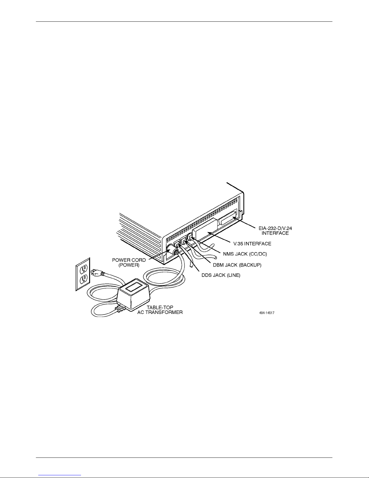
Refer to Figure 1 as you follow these steps.
Procedure
1. Unplug the table-top ac transformer from the ac outlet, then disconnect the power cord from the DSU’s rear
panel (labeled POWER).
2. Disconnect the DDS interface cable (labeled LINE) from the DSU.
3. Disconnect the DBM and NMS interface cables (labeled BACKUP and CC/DC, respectively), if installed.
4. Disconnect the EIA-232-D/V.24 or V.35 interface cable from the DSU.
If a TDM/Flex is being replaced, disconnect the Port 2 interface cable, as well.
Figure 1. Disconnecting the DSU
2
Opening the Unit
This product is designed to protect sensitive components from damage due to
electrostatic discharge (ESD) during normal operation. When performing installation
procedures, however, take proper static control precautions to prevent damage to
equipment. If you are not sure of the proper static control precautions, contact your
nearest sales or service representative.
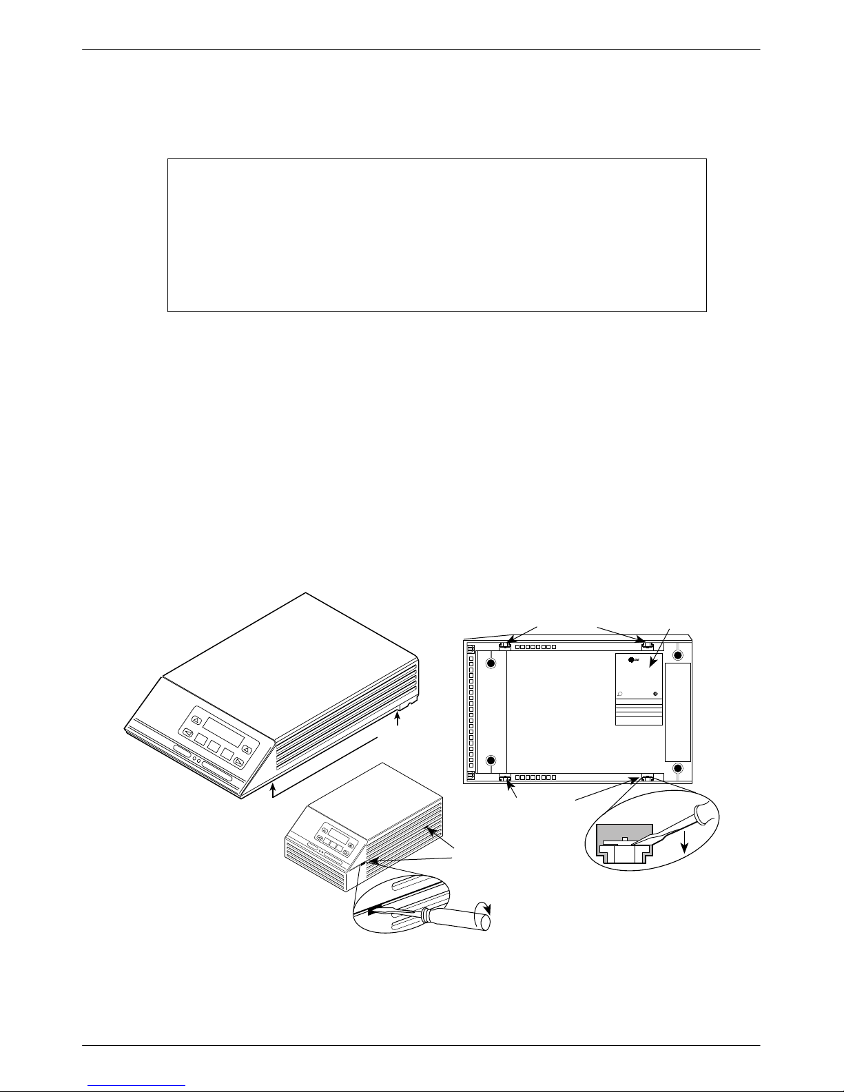
Refer to Figure 2 as you follow these steps.
Procedure
1. Turn the unit upside down.
If a TDM/Flex is being replaced, the unit does not have to be turned over in order to open the case.
2. Using a small flat-head screwdriver, release the four snap tabs holding the base in place.
3. Carefully separate the cover from the base, and return the unit to an upright position.
4. Fold the DSU’s cover over (from the rear of the DSU toward the front).
HANDLING PRECAUTIONS
FOR
ST ATIC SENSITIVE DEVICES
Be careful not to pull the LCD and keypad flat cables from their connectors.
COMSPHERE 3550
SNAP T ABS
COMSPHERE 3610
SNAP T ABS
WITH TDM/FLEX
SNAP T AB
SNAP T AB
NUMBER
P
ara
dyn
e
PEC
MFG DATE
MODEL
SER.NO
NO.
COMM CODE
MADE IN USA
U
L
R
THIS DIGITAL APPARATUS DOES NOT EXCEED THE CLASS A LIMITS FOR RADIO NOISE
EMISSIONS FROM DIGITAL APPARATUS SET OUT IN THE RADIO INTERFERENCE
REGUAALTIONS OF THE CANADIAN DEPARTMENT OF COMMUNICATIONS
FOR USE WITH A CERTIFIED CLASS 2 POWER SUPPLY FOUR UTILISER AVEC LINE
ALIMENTATION CERTIFEE
EN CLASSE 2.
THIS DEVICE COM;OIES WITH PART 15 OF THE FCC RULES OPERATION IS SUBJECT TO
THE FOLLOWING TWO CONDITIONS (1) THIS DEVICE MAY NOT CAUSE HARMFUL
INTERFERENCE AND (2) THIS DEVICE MUST ACCEPT ANY INTERFERENCE RECEIVED
INCLUDING INTERFERENCE THAT MAY CAUSE UNDESIRED OPERATION.
FCC ID: NOT APPLICABLE
SERIAL
R
496-14518-01
Figure 2. Opening the DSU
3
 Loading...