

Page 1

ACCULINK
336x E1 NETWORK
TERMINATION UNIT
OPERATOR’S GUIDE
Document No. 3360-A2-GB20-20
December 1996
Page 2

ACCULINK 336x E1 NTU
ACCULINK
336x E1 Network Termination Unit
Operator’s Guide
3360-A2-GB20-20
3rd Edition (December 1996)
Changes and enhancements to the product and to the information herein will be documented and issued as a new release.
Warranty, Sales, and Service Information
Contact your sales or service representative directly for any help needed. For additional information concerning warranty ,
sales, service, repair, installation, documentation, or training, use one of the following methods:
• Via the Internet: Visit the Paradyne World Wide Web site at http://www.paradyne.com
• Via Telephone: Call our automated call system to receive current information via fax or to speak with a company
representative.
— Within the U.S.A., call 1-800-870-2221
— International, call 727-530-2340
Trademarks
All products and services mentioned herein are the trademarks, service marks, registered trademarks or registered service
marks of their respective owners.
Printed on recycled paper
COPYRIGHT 1996 Paradyne Corporation. All rights reserved.
This publication is protected by federal copyright law. No part of this publication may be copied or distributed, transmitted, transcribed, stored in a retrieval system,
or translated into any human or computer language in any form or by any means, electronic, mechanical, magnetic, manual or otherwise, or disclosed to third parties
without the express written permission of Paradyne Corporation, 8545 126th Avenue North, P.O. Box 2826, Largo, Florida 33779-2826.
Paradyne Corporation makes no representation or warranties with respect to the contents hereof and specifically disclaims any implied warranties of merchantability
or fitness for a particular purpose. Further, Paradyne Corporation reserves the right to revise this publication and to make changes from time to time in the contents
hereof without obligation of Paradyne Corporation to notify any person of such revision or changes.
A December 1996 3360-A2-GB20-20
Page 3

Important Safety Instructions
1. Read and follow all warning notices and instructions marked on the product or included in the
manual.
2. When an AC power source is used, this product is intended to be used with a three-wire
grounding type plug – a plug which has a grounding pin. This is a safety feature. Equipment
grounding is vital to ensure safe operation. Do not defeat the purpose of the grounding type
plug by modifying the plug or using an adapter.
Prior to installation, use an outlet tester or a voltmeter to check the ac receptacle for the
presence of earth ground. If the receptacle is not properly grounded, the installation must not
continue until a qualified electrician has corrected the problem.
If a three-wire grounding type power source is not available, consult a qualified electrician to
determine another method of grounding the equipment.
3. Slots and openings in the cabinet are provided for ventilation. T o ensure reliable operation of
the product and to protect it from overheating, these slots and openings must not be blocked
or covered.
4. Do not allow anything to rest on the power cord and do not locate the product where persons
will walk on the power cord.
Important Instructions
5. Do not attempt to service this product yourself, as opening or removing covers may expose
you to dangerous high voltage points or other risks. Refer all servicing to qualified service
personnel.
6. General purpose cables may be provided with this product. Special cables, which may be
required by the regulatory inspection authority for the installation site, are the responsibility
of the customer. Use a Listed, minimum No. 26 AWG line cord for connection to the High
bit-rate Digital Subscriber Line (HDSL) network.
7. When installed in the final configuration, the product must comply with the applicable Safety
Standards and regulatory requirements of the country in which it is installed. If necessary,
consult with the appropriate regulatory agencies and inspection authorities to ensure
compliance.
8. A rare phenomenon can create a voltage potential between the earth grounds of two or more
buildings. If products installed in separate buildings are interconnected, the voltage potential
may cause a hazardous condition. Consult a qualified electrical consultant to determine
whether or not this phenomenon exists and, if necessary, implement corrective action prior to
interconnecting the products.
9. Input power to the AC voltage configuration of this product must be provided by one of the
following: (1) a UL Listed/CSA certified power source with a Class 2 or Limited Power
Source (LPS) output for use in North America, or (2) a certified power source with a Safety
Extra Low Voltage (SELV) output for use in the country of installation.
Input power to the DC voltage configurations of this product must be provided by one of the
following: (1) a National Electric Code (NEC)/Canadian Electric Code (CEC) Class 2 circuit
for use in North America, or (2) a certified Safety Extra Low Voltage (SELV) circuit input for
use in the country of installation.
10. This product contains a coin cell lithium battery that is only to be replaced at the factory.
Caution: There is a danger of explosion if the battery is incorrectly replaced. Replace only
with the same type. Dispose of used batteries according to the battery manufacturer’s
instructions. Attention: Il y a danger d’explosion s’il y a remplacement incorrect de la
batterie. Remplacer uniquement avec une batterie du même type. Mettre au rebut les batteries
usagées conformément aux instructions du fabricant.
B3360-A2-GB20-20 December 1996
Page 4

ACCULINK 336x E1 NTU
Notices
In addition, if the equipment is to be used with telecommunications circuits, take the following
precautions:
– Never install telephone wiring during a lightning storm.
– Never install telephone jacks in wet locations unless the jack is specifically designed for wet
locations.
– Never touch uninsulated telephone wires or terminals unless the telephone line has been
disconnected at the network interface.
– Use caution when installing or modifying telephone lines.
– Avoid using a telephone (other than a cordless type) during an electrical storm.
There may be a remote risk of electric shock from lightning.
– Do not use the telephone to report a gas leak in the vicinity of the leak.
THIS EQUIPMENT HAS BEEN TESTED AND FOUND TO COMPL Y WITH THE LIMITS FOR A CLASS A DIGITAL DEVICE,
PURSUANT TO PART 15 OF THE FCC RULES. THESE LIMITS ARE DESIGNED TO PROVIDE REASONABLE
PROTECTION AGAINST HARMFUL INTERFERENCE WHEN THE EQUIPMENT IS OPERATED IN A COMMERCIAL
ENVIRONMENT. THIS EQUIPMENT GENERATES, USES, AND CAN RADIATE RADIO FREQUENCY ENERGY AND, IF
NOT INSTALLED AND USED IN ACCORDANCE WITH THE INSTRUCTION MANUAL, MAY CAUSE HARMFUL
INTERFERENCE TO RADIO COMMUNICATIONS. OPERATION OF THIS EQUIPMENT IN A RESIDENTIAL AREA IS
LIKELY TO CAUSE HARMFUL INTERFERENCE IN WHICH CASE THE USER WILL BE REQUIRED TO CORRECT THE
INTERFERENCE AT HIS OWN EXPENSE.
THE AUTHORITY TO OPERATE THIS EQUIPMENT IS CONDITIONED BY THE REQUIREMENTS THAT NO
MODIFICATIONS WILL BE MADE T O THE EQUIPMENT UNLESS THE CHANGES OR MODIFICATIONS ARE EXPRESSLY
APPROVED BY PARADYNE.
TO USERS OF DIGITAL APPARATUS IN CANADA:
THIS CLASS A DIGITAL APPARATUS MEETS ALL REQUIREMENTS OF THE CANADIAN INTERFERENCE-CAUSING
EQUIPMENT REGULATIONS.
CET APPAREIL NUMÉRIQUE DE LA CLASSE A RESPECTE TOUTES LES EXIGENCES DU RÉGLEMENT SUR LE
MATÉRIEL BROUILLEUR DU CANADA.
C December 1996 3360-A2-GB20-20
Page 5

Table of Contents
Preface
Objectives and Reader Assumptions iii. . . . . . . . . . . . . . . . . . . . . . . . .
Related Documents iii. . . . . . . . . . . . . . . . . . . . . . . . . . . . . . . . . . . . . .
Reference Documents iii. . . . . . . . . . . . . . . . . . . . . . . . . . . . . . . . . . . .
1. Introduction
Overview 1-1. . . . . . . . . . . . . . . . . . . . . . . . . . . . . . . . . . . . . . . . . . . . . .
Features 1-1. . . . . . . . . . . . . . . . . . . . . . . . . . . . . . . . . . . . . . . . . . . . . . .
Physical Description 1-3. . . . . . . . . . . . . . . . . . . . . . . . . . . . . . . . . . . . .
2. Installation
Overview 2-1. . . . . . . . . . . . . . . . . . . . . . . . . . . . . . . . . . . . . . . . . . . . . .
Application Examples 2-1. . . . . . . . . . . . . . . . . . . . . . . . . . . . . . . . . . . .
SNMP Connection Examples 2-3. . . . . . . . . . . . . . . . . . . . . . . . . . . . . .
Important Instructions 2-5. . . . . . . . . . . . . . . . . . . . . . . . . . . . . . . . . . . .
Optional Power Sources 2-5. . . . . . . . . . . . . . . . . . . . . . . . . . . . . . . . . . .
Cabling Examples 2-8. . . . . . . . . . . . . . . . . . . . . . . . . . . . . . . . . . . . . . .
Power-Up Self-Test 2-9. . . . . . . . . . . . . . . . . . . . . . . . . . . . . . . . . . . . . .
3. Operation
Overview 3-2. . . . . . . . . . . . . . . . . . . . . . . . . . . . . . . . . . . . . . . . . . . . . .
Using the Front Panel 3-2. . . . . . . . . . . . . . . . . . . . . . . . . . . . . . . . . . . . .
Displaying Unit Identity 3-8. . . . . . . . . . . . . . . . . . . . . . . . . . . . . . . . . .
Displaying LED Conditions 3-10. . . . . . . . . . . . . . . . . . . . . . . . . . . . . . . .
Selecting the G.703 DTE or Data Port for LED Display 3-11. . . . . . . . . .
Changing Configuration Options 3-11. . . . . . . . . . . . . . . . . . . . . . . . . . . .
Configuring the E1 NTU for SNMP Management 3-14. . . . . . . . . . . . . .
Configuring SNMP Traps 3-18. . . . . . . . . . . . . . . . . . . . . . . . . . . . . . . . .
Configuring DS0 Channels 3-20. . . . . . . . . . . . . . . . . . . . . . . . . . . . . . . .
Selecting the Timing Source 3-33. . . . . . . . . . . . . . . . . . . . . . . . . . . . . . .
Acquiring/Releasing the User Interface 3-35. . . . . . . . . . . . . . . . . . . . . . .
Resetting the E1 NTU 3-36. . . . . . . . . . . . . . . . . . . . . . . . . . . . . . . . . . . .
Download Operations 3-36. . . . . . . . . . . . . . . . . . . . . . . . . . . . . . . . . . . .
i3360-A2-GB20-20 December 1996
Page 6

ACCULINK 336x E1 NTU
4. Maintenance
Overview 4-1. . . . . . . . . . . . . . . . . . . . . . . . . . . . . . . . . . . . . . . . . . . . . .
Self-Test Health 4-2. . . . . . . . . . . . . . . . . . . . . . . . . . . . . . . . . . . . . . . . .
Device Health and Status 4-3. . . . . . . . . . . . . . . . . . . . . . . . . . . . . . . . . .
HDSL Loop Performance 4-5. . . . . . . . . . . . . . . . . . . . . . . . . . . . . . . . .
Performance Reports 4-6. . . . . . . . . . . . . . . . . . . . . . . . . . . . . . . . . . . . .
Alarms 4-10. . . . . . . . . . . . . . . . . . . . . . . . . . . . . . . . . . . . . . . . . . . . . . . .
SNMP Traps 4-11. . . . . . . . . . . . . . . . . . . . . . . . . . . . . . . . . . . . . . . . . . . .
Troubleshooting 4-12. . . . . . . . . . . . . . . . . . . . . . . . . . . . . . . . . . . . . . . . .
Test Jacks 4-14. . . . . . . . . . . . . . . . . . . . . . . . . . . . . . . . . . . . . . . . . . . . . .
Test Commands 4-15. . . . . . . . . . . . . . . . . . . . . . . . . . . . . . . . . . . . . . . . .
Remote Loopback T ests 4-15. . . . . . . . . . . . . . . . . . . . . . . . . . . . . . . . . . .
Local Loopback T ests 4-16. . . . . . . . . . . . . . . . . . . . . . . . . . . . . . . . . . . .
Test Patterns 4-21. . . . . . . . . . . . . . . . . . . . . . . . . . . . . . . . . . . . . . . . . . . .
Lamp Test 4-24. . . . . . . . . . . . . . . . . . . . . . . . . . . . . . . . . . . . . . . . . . . . . .
Displaying E1 NTU T est Status 4-25. . . . . . . . . . . . . . . . . . . . . . . . . . . . .
Appendices
Glossary
Index
A. %"!' ! !( *
B. ! #'"!& *
C. "!(%'"! #'"!& *
D. ! &&! !'& *
E. '& *
F. ')"% %&&! !%" *
G. %"!' ! ('"! *
H. $(# !' &' *
ii December 1996 3360-A2-GB20-20
Page 7

Preface
Objectives and Reader
Assumptions
This operator’s guide contains installation, operation,
and maintenance information for the ACCULINK 336x
E1 Network T ermination Unit (NTU).
It is assumed that you are familiar with the operation of
digital data communication equipment and NTUs in
particular. You should also be familiar with Simple
Network Management Protocol (SNMP) if you want your
E1 NTU to be managed by an SNMP manager.
Related Document
7800-A2-GB20 ACCULINK 3100 Series Open
Management Application for
HP OpenView User’s Guide
Reference Documents
• CSA-22.2 No. 950-M89
• CSA 108-M1983
• FCC Part 15
• UL 1950
• Management Information Base for Network
Management of TCP/IP-Based Internets: MIBII.
RFC 1213, March 1991
• Definitions of Managed Objects for the DS1 and E1
Interface T ypes . RFC 1406, January 1993
• Definitions of Managed Objects for RS-232-like
Hardware Devices. RFC 1317, April 1992
• Extensions to the Generic-Interface MIB.
RFC 1229, May 1991
iii3360-A2-GB20-20 December 1996
Page 8

Introduction
Overview 1-1. . . . . . . . . . . . . . . . . . . . . . . . . . . . . . . . . . . . . . . . . . . . . . . . . . . . . . . . . . . . . . . . . . . . . . . . . .
Features 1-1. . . . . . . . . . . . . . . . . . . . . . . . . . . . . . . . . . . . . . . . . . . . . . . . . . . . . . . . . . . . . . . . . . . . . . . . . . .
G.703 DTE Interface 1-2. . . . . . . . . . . . . . . . . . . . . . . . . . . . . . . . . . . . . . . . . . . . . . . . . . . . . . . . . . . . . .
Alarm Message Capability 1-2. . . . . . . . . . . . . . . . . . . . . . . . . . . . . . . . . . . . . . . . . . . . . . . . . . . . . . . . .
Front Panel Emulation 1-2. . . . . . . . . . . . . . . . . . . . . . . . . . . . . . . . . . . . . . . . . . . . . . . . . . . . . . . . . . . . .
SNMP Management Support 1-2. . . . . . . . . . . . . . . . . . . . . . . . . . . . . . . . . . . . . . . . . . . . . . . . . . . . . . . .
Physical Description 1-3. . . . . . . . . . . . . . . . . . . . . . . . . . . . . . . . . . . . . . . . . . . . . . . . . . . . . . . . . . . . . . . . .
Front Panel 1-3. . . . . . . . . . . . . . . . . . . . . . . . . . . . . . . . . . . . . . . . . . . . . . . . . . . . . . . . . . . . . . . . . . . . . .
Rear Panel 1-3. . . . . . . . . . . . . . . . . . . . . . . . . . . . . . . . . . . . . . . . . . . . . . . . . . . . . . . . . . . . . . . . . . . . . .
1
Overview
The E1 NTU acts as an interface between a High
bit-rate Digital Subscriber Line (HDSL) network and the
customer’s Data Terminal Equipment (DTE), converting
signals received from the DTE into the two binary, one
quaternary (2B1Q) signal format for transmission over the
HDSL network.
The E1 NTU’s G.703 DTE interface supports
2.048 Mbps (E1) data that is compatible with the signal
format of ITU Recommendation G.703 and the frame
structure of ITU Recommendation G.704.
In addition to the G.703 DTE interface, the 336x E1
NTUs have one to four EIA 530A synchronous data ports
that may be configured for rates of 64 kbps to 1984 kbps.
The 336x Series consists of a Model 3360 NTU
(2-port), a Model 3364 NTU (4-port), and a Model 3365
NTU (1-port). Differences between these models are
discussed where applicable throughout this guide.
Features
The E1 NTU optimizes network performance with a
wide range of features such as the following:
• Software configuration menu displayed via a liquid
crystal display (LCD) to permit quick and easy
operation, and elimination of complicated hardware
strapping.
• Local or remote configuration and operation
flexibility.
• Several loopback capabilities and test pattern
generators.
• G.703 DTE capability.
• Alarm message display/print capability.
• Front panel emulation via Windows-based Front
Panel Emulation software.
• Network management provided through
industry-standard Simple Network Management
Protocol (SNMP).
1-13360-A2-GB20-20 December 1996
Page 9

ACCULINK 336x E1 NTU
G.703 DTE Interface
The G.703 DTE interface is compatible with the signal
format of ITU Recommendation G.703 and the frame
structure of ITU Recommendation G.704. This interface
allows DTEs/PBXs to share the network with other
high-speed equipment.
Alarm Message Capability
The E1 NTU can be attached, either locally or
remotely , to an ASCII terminal or printer to display or
print alarm messages. The communications (COM) port
can be used as the destination for Alarm Set and Alarm
Clear messages. This enables an ASCII terminal or printer
to monitor the E1 NTU for alarm conditions. Alarms can
also be displayed on a PC that is using a terminal
emulation package.
Front Panel Emulation
The E1 NTU offers functionality through Front Panel
Emulation software that is similar to that provided by the
E1 NTU front panel. The E1 NTU can either be locally or
remotely attached to a 386 or higher personal computer
(PC) that has at least four megabytes (MB) of
random-access memory (RAM). (An external modem is
required for remote attachment.) A copy of the E1 NTU
front panel appears on the PC. The functionality of the
front panel is available by clicking on the function keys
with the mouse rather than by pressing keys from the
actual front panel. For more information, refer to
Appendix G, Front Panel Emulation.
SNMP Management Support
SNMP is a network management protocol that is used
to monitor network performance and status, and to report
alarms (i.e., traps). T o function, SNMP requires a manager
consisting of a software program housed within a
workstation or PC; an agent consisting of a software
program housed within a device (e.g., the E1 NTU); and a
Management Information Base (MIB) consisting of a
database of managed objects.
Users of the external SNMP manager can issue “Get”
and “Set” commands to an object in the SNMP database
maintained by the E1 NTU.
The E1 NTU can be managed by any industry-standard
SNMP manager. Paradyne provides an SNMP application
that runs on a Hewlett-Packard HP OpenView network
management platform. For more information, refer to the
ACCULINK 3100 Series Open Management Application
for HP OpenView User’s Guide.
The E1 NTU supports the following MIBs:
• MIB II – Defines the general objects for use in
Transmission Control Protocol/Internet Protocol
(TCP/IP) internets and provides general
information about the E1 NTU. MIB II is
backward-compatible with MIB I.
• DS1/E1 MIB – Defines objects for managing E1
interfaces and supports the network and G.703 DTE
interfaces on the E1 NTU.
• RS-232-like MIB – Defines objects for managing
RS-232-type interfaces (e.g., RS-422, RS-423, etc.)
and supports synchronous data ports (PORTs 1– 4)
and management communication ports (AUX and
COM ports) on the E1 NTU.
• Generic-Interface Extension MIB – An extension to
MIB II that defines additional objects for control of
generic interfaces in MIB II. It supports control of
tests on the G.703 DTE and synchronous data
interfaces that are not supported by other MIBs.
• Enterprise MIB – Defines objects that are unique to
Paradyne devices.
Two link layer protocols, Point-to-Point Protocol (PPP)
and Serial Line Internet Protocol (SLIP), are supported for
connection to an external SNMP manager or network
device (e.g., a router).
The SNMP manager or network device can be directly
connected to the communications (COM) port. An
external LAN Adapter can be connected to either the
COM port or the auxiliary (AUX) port to provide Ethernet
connectivity. Also, the E1 NTU can be daisy chained
together by connecting the COM port of one device to the
AUX port of the other, providing SNMP connectivity.
The SNMP management system can communicate to
the E1 NTU remotely through the Facility Data Link
(FDL) or (for 2-port and 4-port E1 NTUs) the
synchronous data port’s Embedded Data Link (EDL).
FDL provides an in-band channel for performance and
control signals on the network interface. It uses the spare
in time-slot zero as defined in ITU
bit S
a4
Recommendation G.704. EDL provides the ability to
detect and synchronize on a framing pattern, provides
cyclic redundancy checking (CRC), and maintains
near-end and far-end performance statistics.
1-2 December 1996 3360-A2-GB20-20
Page 10
Introduction
1
Physical Description
The 336x Series consists of a Model 3360 NTU
(2-port), a Model 3364 NTU (4-port), and a Model 3365
NTU (1-port).
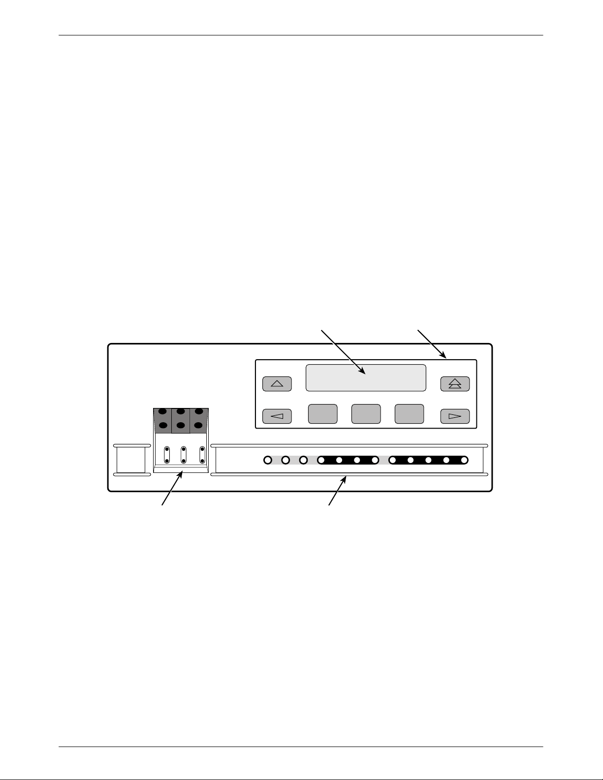
Front Panel
The E1 NTU front panel (Figure 1-1) contains,
• One 2-line, 16-alphanumeric-character-per-line
liquid crystal display (LCD)
• One 7-button keypad (three Function and four
directional keys)
• Twelve light-emitting diodes (LEDs)
• Six test jacks
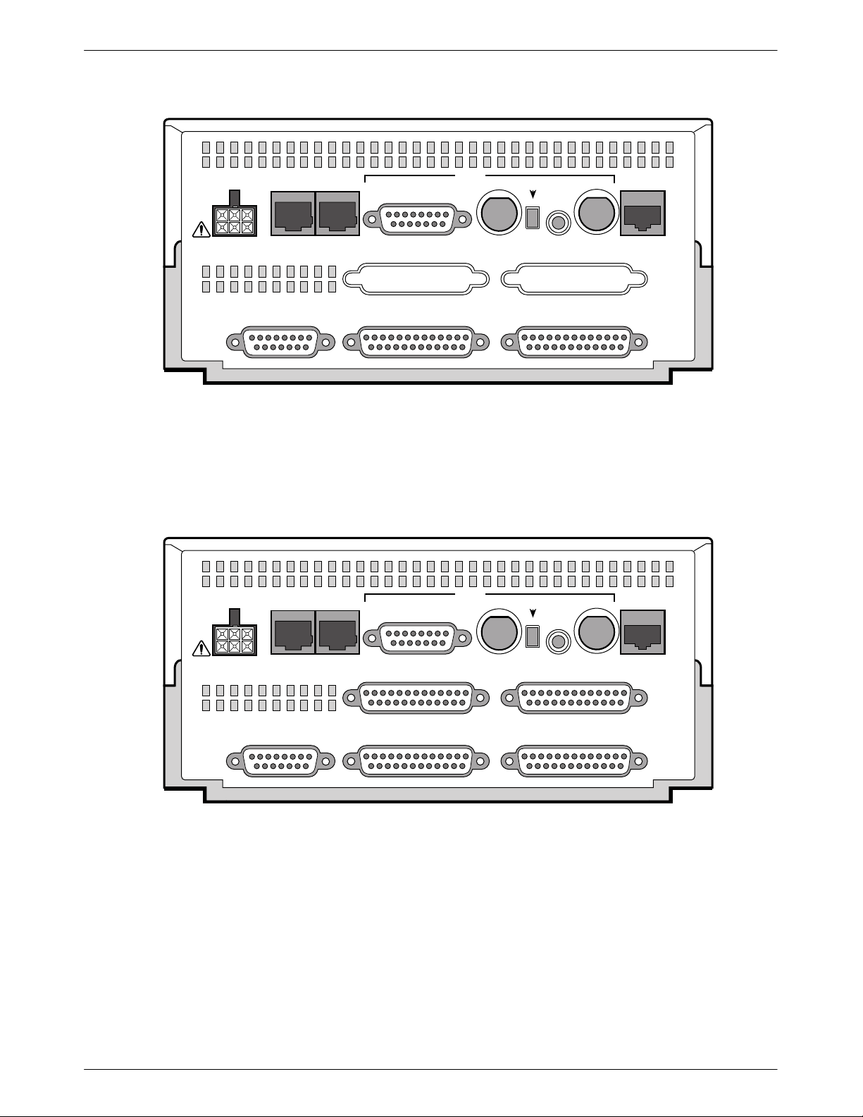
Rear Panel
The E1 NTU rear panel contains the connectors and
switches required for the operation of the E1 NTU
(Figures 1-2, 1-3, and 1-4). The connectors and switches
are described in Table 1-1.
LCD
KEYPAD
F1 F2 F3
E1
HDSL
LINEE1MON
LINE
Lp1
Lp2InOutInOut
TEST JACKS LEDs
OK
FAIL TEST SIG1 OOF ALRM
Figure 1-1. Front Panel
SIG2 SIG ALRM PDVOOF BPV
NETWORK RXD
DTR TXD CTS RTS
496-14728-0
1-33360-A2-GB20-20 December 1996
Page 11
ACCULINK 336x E1 NTU
3
4
AUX
POWER
CAUTION: AUX PORT OR COM PORT MUST
NOT BE CONNECTED TO HDSL NETWORK
PORT
COM
PORT
Figure 1-2. Model 3360 Rear Panel
G.703
TX RX
75
RX SHIELD
Ω
OPEN
EARTH
120
IN
OUT
75
Ω
Ω
120
Ω
PORT 3 PORT 4
PORT 2PORT 1CLOCK IN
75
Ω
HDSL
NETWORK
495-1473
AUX
POWER
CAUTION: AUX PORT OR COM PORT MUST
NOT BE CONNECTED TO HDSL NETWORK
PORT
COM
PORT
Figure 1-3. Model 3364 Rear Panel
G.703
TX RX
75
RX SHIELD
Ω
OPEN
EARTH
120
IN
OUT
75
Ω
Ω
120
Ω
PORT 3 PORT 4
PORT 2PORT 1CLOCK IN
75
Ω
HDSL
NETWORK
495-1473
1-4 December 1996 3360-A2-GB20-20
Page 12
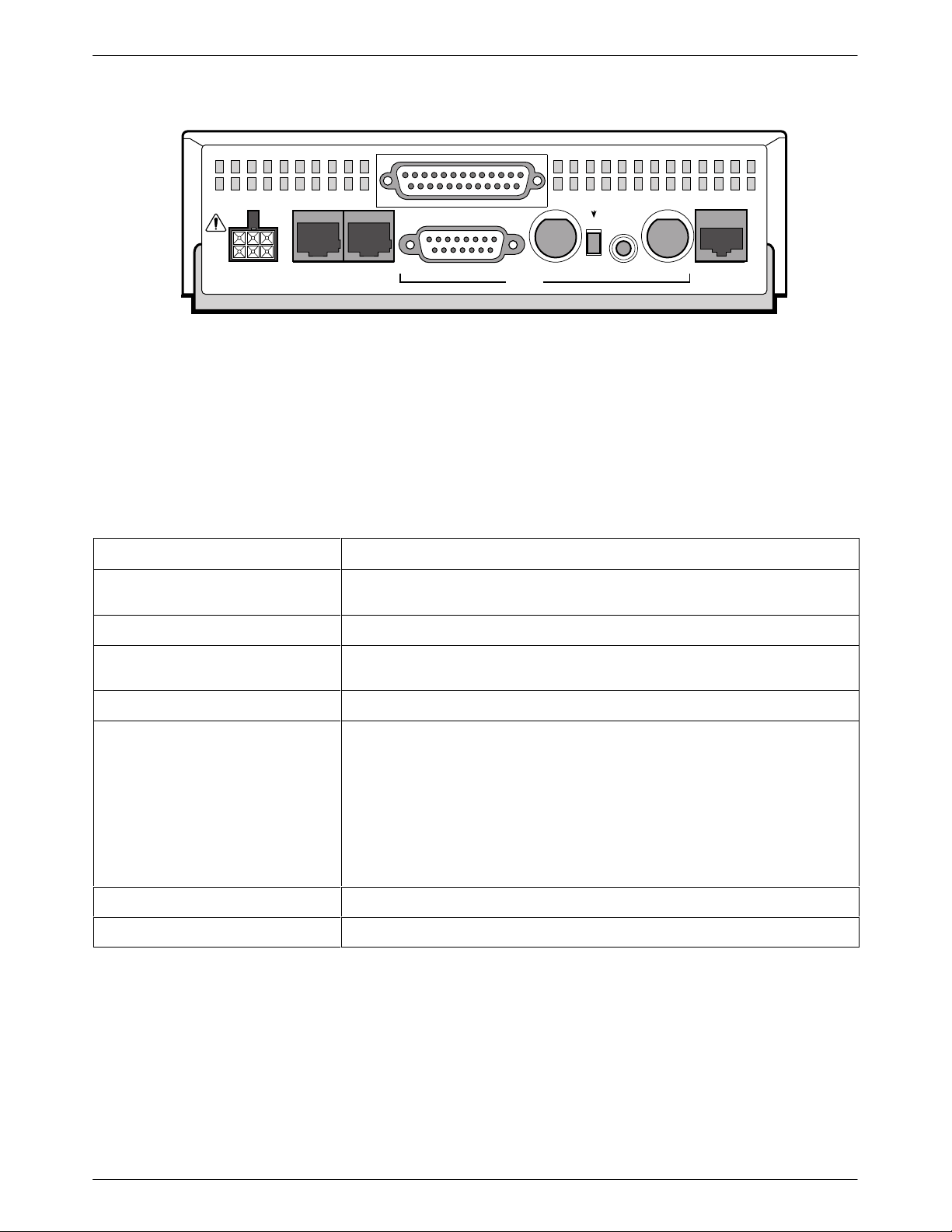
2
POWER
PORT 1
AUX
PORT
COM
PORT
120
Ω
Figure 1-4. Model 3365 Rear Panel
TX RX
RX SHIELD
OPEN
EARTH
75
Ω
G.703
120
IN
OUT
75
Introduction
Ω
Ω
HDSL
NETWORK
495-1473
75
Ω
Table 1-1
Rear Panel Connectors and Switches
Name
POWER Supplies power to the E1 NTU by providing an attachment for the ac power
module or the optional dc power cable (+24 or –48 Vdc).
AUX PORT Supports SNMP LAN Adapter or daisy-chain connections.
COM PORT Provides access to a locally connected PC, an ASCII terminal or printer, or an
SNMP management link.
HDSL NETWORK Provides access to the HDSL network.
G.703—120Ω
G.703—120Ω/75Ω (switch)
G.703—75Ω TX/RX
G.703—RX SHIELD (switch) Selects either an “open” or “earth” shield connection for the 75 ohm RX interface.
CLOCK IN (Models 3360/3364) Used to attach an external clock to the E1 NTU.
PORTs 1–4 Used to connect the customer’s synchronous data DTE to the E1 NTU.
Provides a 120 ohm balanced G.703 interface.
Selects either a 120 ohm balanced G.703 interface (the switch is IN) or a 75 ohm
unbalanced G.703 interface (the switch is OUT).
Provides two BNC connectors (Transmit and Receive) for a 75 ohm unbalanced
G.703 interface.
(This switch must be set to “open” when using the 120 ohm interface.)
Function
1-53360-A2-GB20-20 December 1996
Page 13
Installation
1
Overview 2-1. . . . . . . . . . . . . . . . . . . . . . . . . . . . . . . . . . . . . . . . . . . . . . . . . . . . . . . . . . . . . . . . . . . . . . . . . .
Application Examples 2-1. . . . . . . . . . . . . . . . . . . . . . . . . . . . . . . . . . . . . . . . . . . . . . . . . . . . . . . . . . . . . . . .
SNMP Connection Examples 2-3. . . . . . . . . . . . . . . . . . . . . . . . . . . . . . . . . . . . . . . . . . . . . . . . . . . . . . . . . .
Important Instructions 2-5. . . . . . . . . . . . . . . . . . . . . . . . . . . . . . . . . . . . . . . . . . . . . . . . . . . . . . . . . . . . . . . .
Optional Power Sources 2-5. . . . . . . . . . . . . . . . . . . . . . . . . . . . . . . . . . . . . . . . . . . . . . . . . . . . . . . . . . . . . .
Installing the +24 Vdc Power Supply 2-5. . . . . . . . . . . . . . . . . . . . . . . . . . . . . . . . . . . . . . . . . . . . . . . . .
Installing the Single –48 Vdc Power Supply 2-6. . . . . . . . . . . . . . . . . . . . . . . . . . . . . . . . . . . . . . . . . . . .
Installing the Redundant –48 Vdc Power Supply 2-7. . . . . . . . . . . . . . . . . . . . . . . . . . . . . . . . . . . . . . . .
Cabling Examples 2-8. . . . . . . . . . . . . . . . . . . . . . . . . . . . . . . . . . . . . . . . . . . . . . . . . . . . . . . . . . . . . . . . . . .
Power-Up Self-Test 2-9. . . . . . . . . . . . . . . . . . . . . . . . . . . . . . . . . . . . . . . . . . . . . . . . . . . . . . . . . . . . . . . . . .
2
Overview
This chapter contains information for installing your
E1 NTU. It includes application examples, cabling, and
power-up information.
Application Examples
The E1 NTU acts as an interface between a High
bit-rate Digital Subscriber Line (HDSL) network and the
customer’s equipment.
PBX
The E1 NTU is connected to the customer’s equipment
through one of the synchronous data ports (PORTs 1– 4)
or the G.703 DTE port. It is connected to the network
through the HDSL Network interface.
The E1 NTU normally operates in conjunction with a
Line T ermination Unit (LTU) that is installed in an
ACCULINK Access Controller (AAC).
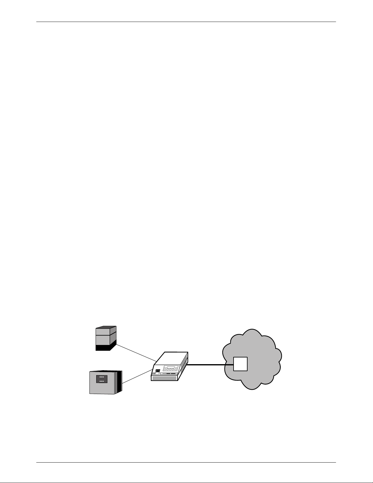
Some common applications for the E1 NTU are:
• Shared access to network-based services
(Figure 2-1).
• Point-to-Point LAN interconnection (Figure 2-2).
• Fractional E1 network applications (Figure 2-3).
NETWORK
SERVICES
HDSL
AAC
LTU
LAN
ROUTER
NTU
496-14736-0
Figure 2-1. Shared Access Application Example
2-13360-A2-GB20-20 December 1996
Page 14
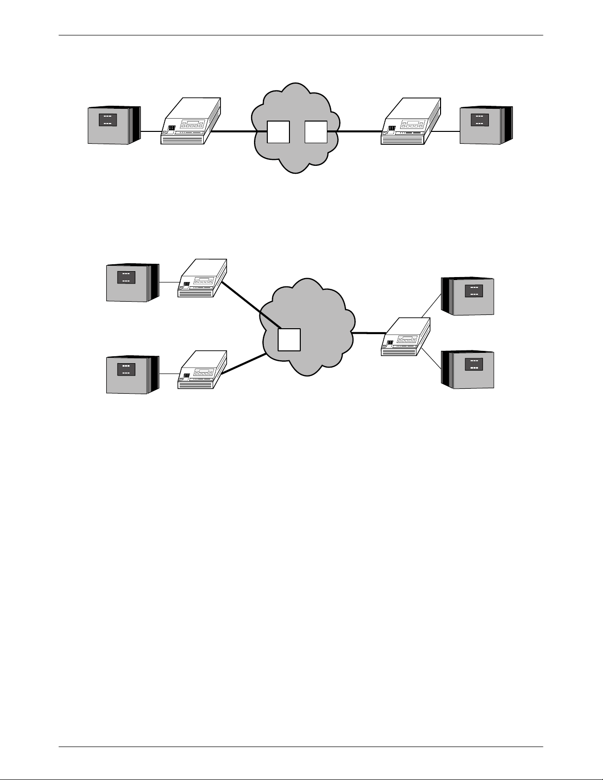
ACCULINK 336x E1 NTU
1
1
NETWORK
HDSL HDSL
AAC
LTU
AAC
LTU
LAN
ROUTER
ROUTER
ROUTER
LAN
LAN
NTU
Figure 2-2. Point-to-Point Application Example
HDSL
NTU
FRACTIONAL
NETWORK
AAC
LTU
E1
DSU/CSU
E1
NTU
DSU/CSU
LAN
ROUTER
496-14735-0
LAN
ROUTER
LAN
ROUTER
496-14737-0
Figure 2-3. Fractional E1 Application Example
2-2 December 1996 3360-A2-GB20-20
Page 15
Installation
SNMP Connection Examples
The E1 NTU can be connected to an SNMP
management system in a number of ways. Some examples
include:
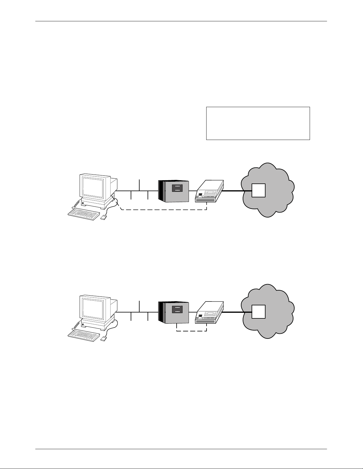
• Directly connecting the COM port to the SNMP
manager (Figure 2-4).
• Connecting the COM port to a network device (e.g.,
a router) for SNMP management (Figure 2-5).
• Connecting the COM port or the AUX port to an
external LAN Adapter for Ethernet SNMP
connectivity (Figure 2-6).
SNMP
ETHERNET
LAN
ROUTER
SNMP
PPP/SLIP
• Daisy chaining the COM port of one device to the
AUX port of the other to provide SNMP
connectivity (Figure 2-7).
• Remotely managing the E1 NTU through the
Facility Data Link (FDL) or the synchronous data
port’s Embedded Data Link (EDL) ( Figure 2-8 ).
NOTE
EDL is only available on 2-port
and 4-port E1 NTUs.
NTU
HDSL
NETWORK
AAC
LTU
496-14738-01
Figure 2-4. Direct Connection to an SNMP Manager
SNMP
ETHERNET
LAN
ROUTER
NTU
SNMP
PPP/SLIP
Figure 2-5. Connection through a Router to SNMP
HDSL
NETWORK
AAC
LTU
496-14739-01
2-33360-A2-GB20-20 December 1996
Page 16
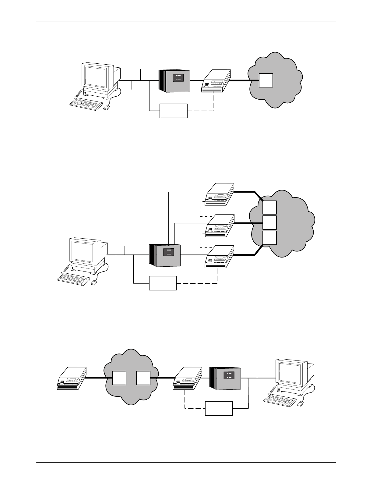
ACCULINK 336x E1 NTU
1
SNMP
NMS
ETHERNET
LAN
ROUTER
LAN
ADAPTER
NTU
HDSL
SNMP
PPP
Figure 2-6. Connection through a LAN Adapter to SNMP
NTU
HDSL
NETWORK
AAC
LTU
496-14740-01
NTU
SNMP
NMS
ETHERNET
LAN
ROUTER
LAN
ADAPTER
SNMP
PPP
SNMP
PPP
SNMP
PPP
NTU
HDSL
NTU
HDSL
Figure 2-7. LAN Adapter and Daisy Chaining for SNMP Support
LAN
ROUTER
LAN
ADAPTER
ETHERNET
HDSL
SNMP
FDL/EDL
NETWORK
AAC
LTU
AAC
NTU
HDSL
LTU
SNMP
PPP
AAC
LTU
AAC
LTU
AAC
LTU
NETWORK
496-14741-01
496-14742-0
Figure 2-8. Remote SNMP Management through FDL/EDL
2-4 December 1996 3360-A2-GB20-20
Page 17

Installation
3
Important Instructions
Read and follow all warning notices and instructions
marked on the E1 NTU or included in this guide.
For a complete listing of the safety instructions, see the
Important Safety Instructions section at the beginning of
this guide.
HANDLING PRECAUTIONS
FOR
ST ATIC-SENSITIVE DEVICES
This product is designed to protect
sensitive components from damage
due to electrostatic discharge (ESD)
during normal operation. When
performing installation procedures,
however, take proper static control
precautions to prevent damage to
equipment. If you are not sure of the
proper static control precautions,
contact your nearest sales or service
representative.
Using the optional dc power cable, the E1 NTU is
capable of operating on either a +24 Vdc power source,
–48 Vdc single source battery, or –48 Vdc redundant
source batteries (for power backup). T o select the power,
choose one of the following power supply types.
Installing the +24 Vdc Power Supply
To install the E1 NTU using a +24 Vdc power supply,
refer to Figure 2-9 and use the following procedure.
To install the +24 Vdc power supply,
1. Connect the green wire to a suitable earth ground.
2. Connect the white wire to the +24 Vdc return.
3. Connect the orange wire to the +24 Vdc source.
4. Cut the black, red and blue wires off at the outer
insulation.
5. Plug the power connector into the E1 NTU.
Optional Power Sources
The E1 NTU is typically powered by the ac power
module. Use the following procedures only if you want
to use an optional dc power source.
NTU POWER
PLUG
1
2
3
4
5
6
BLACK
RED
GREEN
WHITE
ORANGE
BLUE
CABLE NUMBER 3100-F1-520
Figure 2-9. +24 Vdc Power Supply Pinouts
TO CUSTOMER-SUPPLIED BATTERY
X
X
EARTH GROUND
+24 VDC RETURN
+24 VDC SOURCE
X
495-1474
2-53360-A2-GB20-20 December 1996
Page 18

ACCULINK 336x E1 NTU
4
Installing the Single –48 Vdc Power Supply
To install the E1 NTU using a single source –48 Vdc
power supply, refer to Figure 2-10 and use the following
procedure.
To install the –48 Vdc single source power supply,
1. Connect the black and red wires to the –48 Vdc
return source.
NTU POWER
PLUG
1
2
3
4
5
6
BLACK
RED
GREEN
WHITE
ORANGE
BLUE
CABLE NUMBER 3100-F1-520
2. Connect the green wire to a suitable earth ground.
3. Connect the orange and blue wires to the –48 Vdc
input source.
4. Cut the white wire off at the outer insulation.
5. Plug the power connector into the E1 NTU.
TO CUSTOMER-SUPPLIED BATTERY
–48 VDC RETURN
EARTH GROUND
X
–48 VDC INPUT
495-1474
Figure 2-10. – 48 Vdc Single Source Power Supply Pinouts
2-6 December 1996 3360-A2-GB20-20
Page 19

Installation
5
Installing the Redundant –48 Vdc Power
Supply
To install the E1 NTU using a redundant –48 Vdc
power supply, refer to Figure 2-11 and use the following
procedure.
To install the redundant –48 Vdc power supply,
1. Connect the black wire to the –48 Vdc return
source B.
2. Connect the red wire to the –48 Vdc return
source A.
NTU POWER
PLUG
1
2
3
4
5
6
BLACK
RED
GREEN
WHITE
ORANGE
BLUE
3. Connect the green wire to a suitable earth ground.
4. Connect the orange wire to the –48 Vdc input
source B.
5. Connect the blue wire to the –48 Vdc input
source A.
6. Cut the white wire off at the outer insulation.
7. Plug the power connector into the E1 NTU.
TO CUSTOMER-SUPPLIED BATTERY
–48 VDC RETURN B
–48 VDC RETURN A
EARTH GROUND
X
–48 VDC INPUT B
–48 VDC INPUT A
CABLE NUMBER 3100-F1-520
495-1474
Figure 2-11. –48 Vdc Redundant Source Power Supply Pinouts
2-73360-A2-GB20-20 December 1996
Page 20
ACCULINK 336x E1 NTU
6
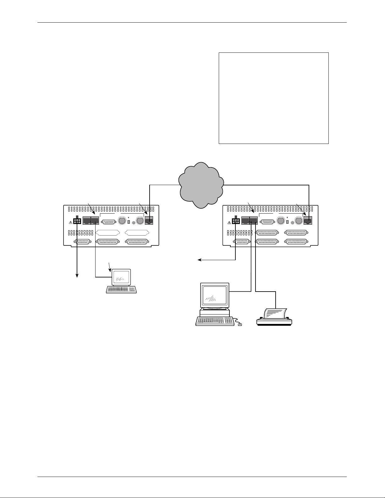
Cabling Examples
The E1 NTU is supplied with an ac power module.
Optional cables that you can order from the company
are described in Appendix D, Pin Assignments.
Figure 2-12 illustrates some cabling examples.
COM PORT
COM
AUX
POWER
CAUTION: AUX PORT OR COM PORT MUST
NOT BE CONNECTED TO HDSL NETWORK
PORT
PORT
120Ω
PORT 3 PORT 4
PORT 1 PORT 2CLOCK IN
HDSL
NETWORK
G.703
TX RX
RX SHIELD
OPEN
EARTH
75Ω
HDSL
NETWORK
120Ω
IN
OUT
75Ω
75Ω
The 120Ω/75Ω switch selects
either the 120 ohm balanced
G.703 interface or the 75 ohm
unbalanced G.703 interface. The
RX SHIELD switch selects either
an “open” or “earth” shield
connection for the 75 ohm RX
interface. (This switch must be set
to “open” when using the 120 ohm
interface.)
HDSL HDSL
NTU
NETWORK
NTU
COM PORT
COM
AUX
POWER
CAUTION: AUX PORT OR COM PORT MUST
NOT BE CONNECTED TO HDSL NETWORK
PORT
PORT
NOTE
HDSL
NETWORK
G.703
TX RX
RX SHIELD
120Ω
PORT 3 PORT 4
PORT 1 PORT 2CLOCK IN
120Ω
OPEN
IN
EARTH
OUT
75Ω
75Ω
HDSL
NETWORK
75Ω
TO AC
POWER
MODULE
SERIAL
PORT
3100-F1-550
NOTE:
3100 SERIES
FRONT PANEL
EMULATION
SOFTWARE,
3100-C1-010
TO DC
POWER
(OPTIONAL)
3100-F1-520
SNMP
MANAGER
Figure 2-12. Cabling Examples
3100-F1-540
OR
495-1474
2-8 December 1996 3360-A2-GB20-20
Page 21
Installation
7
8
7
9
Power-Up Self-Test
After you connect the E1 NTU to a power source, the
unit performs the power-up self-test to ensure that it is in
good working order. The E1 NTU performs this test on
itself upon power-up or after a device reset, unless it has
been disabled by the Self-T est configuration option (see
Appendix C, Configuration Options).
The self-test includes a basic processor test, a limited
memory test, a code checksum test, and basic verification
tests of the internal components. The front panel LCD
displays the progress and pass/fail status of these
power-up tests.
The power-up self-test consists of the following steps:
1. Once the E1 NTU is plugged in, the In Progress
screen appears and the Fail LED blinks ON and
Off continuously.
Self-Test:
In Progress
F1
F2
F3
If the self-test fails, the Failed screen appears for
five seconds. The Fail LED lights, and an
eight-digit failure code (xxxxxxxx) is displayed for
use by service personnel to determine the cause of
the self-test failure. The E1 NTU continues to try
to operate. If you are in doubt about the results of
the self-test, use the Self-T est Health command to
display the status of this test (see the Self-Test
Health section in Chapter 4, Maintenance).
Self-Test:
xxxxxxxx
F1
F2
ALRM SIG ALRM PDVOOF BPV
NETWORK RXD
F3
OK
FAIL
Failed
TEST SIG1 SIG2 OOF
4. The top-level menu screen appears.
E1 HDSL NTU
Stat Test Cnfig
CTS RTSTXDDTR
495-1474
OK
FAIL
TEST SIG1 SIG2 OOF
ALRM SIG ALRM PDVOOF BPV
NETWORK RXD
CTS RTSTXDDTR
495-1474
2. All the LEDs then start to flash simultaneously in
the pattern twice ON, then Off. Then, the LCD
begins to flash characters and numbers in the same
pattern, alternating with the flashing LEDs.
3. If the self-test is successful, the Passed screen
appears for one second, the Fail LED turns Off
and the OK LED lights.
Self-Test:
Passed
F3
DTR TXD CTS RTS
495-1474
OK
FAIL
F1
TEST SIG1 SIG2 OOF
NETWORK RXD
F2
ALRM SIG ALRM PDVOOF BPV
OK
FAIL
F1
TEST SIG1 SIG2 OOF
NETWORK RXD
F2
ALRM SIG ALRM PDVOOF BPV
F3
DTR TXD CTS RTS
495-1474
2-93360-A2-GB20-20 December 1996
Page 22

Operation
Overview 3-2. . . . . . . . . . . . . . . . . . . . . . . . . . . . . . . . . . . . . . . . . . . . . . . . . . . . . . . . . . . . . . . . . . . . . . . . . .
Using the Front Panel 3-2. . . . . . . . . . . . . . . . . . . . . . . . . . . . . . . . . . . . . . . . . . . . . . . . . . . . . . . . . . . . . . . .
LCD 3-3. . . . . . . . . . . . . . . . . . . . . . . . . . . . . . . . . . . . . . . . . . . . . . . . . . . . . . . . . . . . . . . . . . . . . . . . . . .
Keypad. 3-3. . . . . . . . . . . . . . . . . . . . . . . . . . . . . . . . . . . . . . . . . . . . . . . . . . . . . . . . . . . . . . . . . . . . . . . .
Test Jacks. 3-4. . . . . . . . . . . . . . . . . . . . . . . . . . . . . . . . . . . . . . . . . . . . . . . . . . . . . . . . . . . . . . . . . . . . . .
LEDs 3-4. . . . . . . . . . . . . . . . . . . . . . . . . . . . . . . . . . . . . . . . . . . . . . . . . . . . . . . . . . . . . . . . . . . . . . . . . .
Displaying Unit Identity 3-8. . . . . . . . . . . . . . . . . . . . . . . . . . . . . . . . . . . . . . . . . . . . . . . . . . . . . . . . . . . . . .
Displaying LED Conditions 3-10. . . . . . . . . . . . . . . . . . . . . . . . . . . . . . . . . . . . . . . . . . . . . . . . . . . . . . . . . . .
Selecting the G.703 DTE or Data Port for LED Display 3-11. . . . . . . . . . . . . . . . . . . . . . . . . . . . . . . . . . . . .
Changing Configuration Options 3-11. . . . . . . . . . . . . . . . . . . . . . . . . . . . . . . . . . . . . . . . . . . . . . . . . . . . . . .
Displaying/Editing Configuration Options 3-12. . . . . . . . . . . . . . . . . . . . . . . . . . . . . . . . . . . . . . . . . . . . .
Saving Edit Changes 3-13. . . . . . . . . . . . . . . . . . . . . . . . . . . . . . . . . . . . . . . . . . . . . . . . . . . . . . . . . . . . . .
Selecting/Copying to a Specific Port 3-13. . . . . . . . . . . . . . . . . . . . . . . . . . . . . . . . . . . . . . . . . . . . . . . . . .
Configuring the E1 NTU for SNMP Management 3-14. . . . . . . . . . . . . . . . . . . . . . . . . . . . . . . . . . . . . . . . . .
Selecting the Port 3-14. . . . . . . . . . . . . . . . . . . . . . . . . . . . . . . . . . . . . . . . . . . . . . . . . . . . . . . . . . . . . . . . .
Setting the IP Address 3-15. . . . . . . . . . . . . . . . . . . . . . . . . . . . . . . . . . . . . . . . . . . . . . . . . . . . . . . . . . . . .
Selecting the Link Layer Protocol 3-16. . . . . . . . . . . . . . . . . . . . . . . . . . . . . . . . . . . . . . . . . . . . . . . . . . . .
Specifying the Community Name(s) and Access Type(s) 3-17. . . . . . . . . . . . . . . . . . . . . . . . . . . . . . . . . .
Configuring SNMP Traps 3-18. . . . . . . . . . . . . . . . . . . . . . . . . . . . . . . . . . . . . . . . . . . . . . . . . . . . . . . . . . . . .
Enabling SNMP Trap Messages 3-18. . . . . . . . . . . . . . . . . . . . . . . . . . . . . . . . . . . . . . . . . . . . . . . . . . . . .
Selecting the Number of Trap Managers 3-19. . . . . . . . . . . . . . . . . . . . . . . . . . . . . . . . . . . . . . . . . . . . . . .
Configuring a Destination for SNMP Traps 3-19. . . . . . . . . . . . . . . . . . . . . . . . . . . . . . . . . . . . . . . . . . . .
Configuring DS0 Channels 3-20. . . . . . . . . . . . . . . . . . . . . . . . . . . . . . . . . . . . . . . . . . . . . . . . . . . . . . . . . . . .
Displaying DS0 Channel Assignments 3-27. . . . . . . . . . . . . . . . . . . . . . . . . . . . . . . . . . . . . . . . . . . . . . . .
Allocating Data Ports 3-28. . . . . . . . . . . . . . . . . . . . . . . . . . . . . . . . . . . . . . . . . . . . . . . . . . . . . . . . . . . . . .
Block Channel Assignment Method 3-29. . . . . . . . . . . . . . . . . . . . . . . . . . . . . . . . . . . . . . . . . . . . . . . . . .
Individual Channel Assignment Method 3-30. . . . . . . . . . . . . . . . . . . . . . . . . . . . . . . . . . . . . . . . . . . . . . .
Allocating DS0 Channels from the G.703 DTE Interface to the Network Interface 3-30. . . . . . . . . . . . . .
Clearing DS0 Channel Allocation 3-32. . . . . . . . . . . . . . . . . . . . . . . . . . . . . . . . . . . . . . . . . . . . . . . . . . . .
Selecting the Timing Source 3-33. . . . . . . . . . . . . . . . . . . . . . . . . . . . . . . . . . . . . . . . . . . . . . . . . . . . . . . . . . .
Configuring for Network Timing 3-34. . . . . . . . . . . . . . . . . . . . . . . . . . . . . . . . . . . . . . . . . . . . . . . . . . . .
Configuring for External Timing 3-34. . . . . . . . . . . . . . . . . . . . . . . . . . . . . . . . . . . . . . . . . . . . . . . . . . . . .
Acquiring/Releasing the User Interface 3-35. . . . . . . . . . . . . . . . . . . . . . . . . . . . . . . . . . . . . . . . . . . . . . . . . .
Acquiring the Active User Interface 3-35. . . . . . . . . . . . . . . . . . . . . . . . . . . . . . . . . . . . . . . . . . . . . . . . . .
Releasing the Active User Interface 3-35. . . . . . . . . . . . . . . . . . . . . . . . . . . . . . . . . . . . . . . . . . . . . . . . . .
Resetting the E1 NTU 3-36. . . . . . . . . . . . . . . . . . . . . . . . . . . . . . . . . . . . . . . . . . . . . . . . . . . . . . . . . . . . . . . .
Download Operations 3-36. . . . . . . . . . . . . . . . . . . . . . . . . . . . . . . . . . . . . . . . . . . . . . . . . . . . . . . . . . . . . . . .
3
3-13360-A2-GB20-20 December 1996
Page 23
ACCULINK 336x E1 NTU
1
Overview
This chapter contains information for operating your
E1 NTU. It includes a description of the front panel and
sample procedures for configuring the E1 NTU.
Using the Front Panel
The E1 NTU front panel (Figure 3-1) consists of an
LCD, a keypad, test jacks, and 12 LEDs.
NOTE
You can display a graphical
representation of the E1 NTU
front panel on an attached PC
(see Appendix G,
Emulation
LCD
F1 F2 F3
).
KEYPAD
Front Panel
E1
HDSL
LINEE1MON
LINE
Lp1
Lp2InOutInOut
TEST JACKS LEDs
OK
FAIL TEST SIG1 OOF ALRM
Figure 3-1. E1 NTU Front Panel
SIG2 SIG ALRM PDVOOF BPV
NETWORK RXD
DTR TXD CTS RTS
496-14728-0
3-2 December 1996 3360-A2-GB20-20
Page 24

Operation
LCD
The LCD (Figure 3-2) displays two types of data:
• Messages such as alarms, command/test
completion, and action in progress
• Front panel menu tree information (see
Appendix A, Front Panel Menu)
F1 F2
Figure 3-2. LCD
The LCD displays status messages as requested via the
Device Health and Status branch of the front panel menu
(see the Device Health and Status section in Chapter 4,
Maintenance). In addition, the highest level status
message appears on the front panel automatically if no
front panel action has occurred at the E1 NTU for the past
five minutes.
The LCD also lists commands, configuration options,
and test results. In most cases, the top line shows the
command or option name and default value, while the
second line displays options and responses. When a
response is required, select from the options displayed
directly above the Function keys (F1, F2, F3); make your
choice by pressing the corresponding Function key.
F3
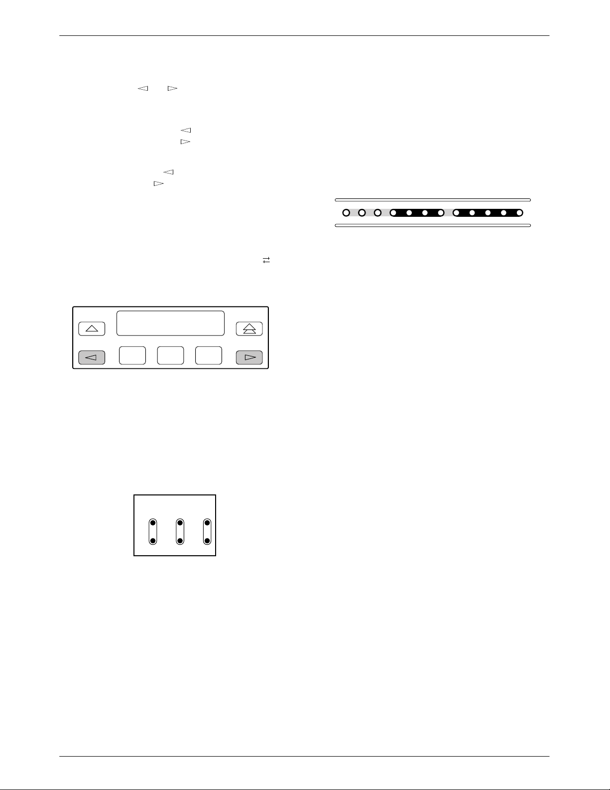
Keypad
The 7-button keypad (Figure 3-3) enables you to
navigate through the menu tree and select choices
presented on the second line of the LCD.
F1 F2
Figure 3-3. Keypad
Use the
key to move up the menu.
F1 F2
Use the key to exit any part of the menu in which
you may be operating. You immediately return to the
top-level menu screen shown on the front panel menu (see
Appendix A, Front Panel Menu).
F3
F3
F1 F2
F3
Use the Function (F1, F2, F3) keys to make selections
from the choices presented on the second line of the LCD.
When this line presents choices, it is generally divided
into three sections, each displayed directly above one of
the Function keys. When your choice appears above one
of the Function keys, press that key to select that choice.
F1 F2
F3
3-33360-A2-GB20-20 December 1996
Page 25
ACCULINK 336x E1 NTU
3
9
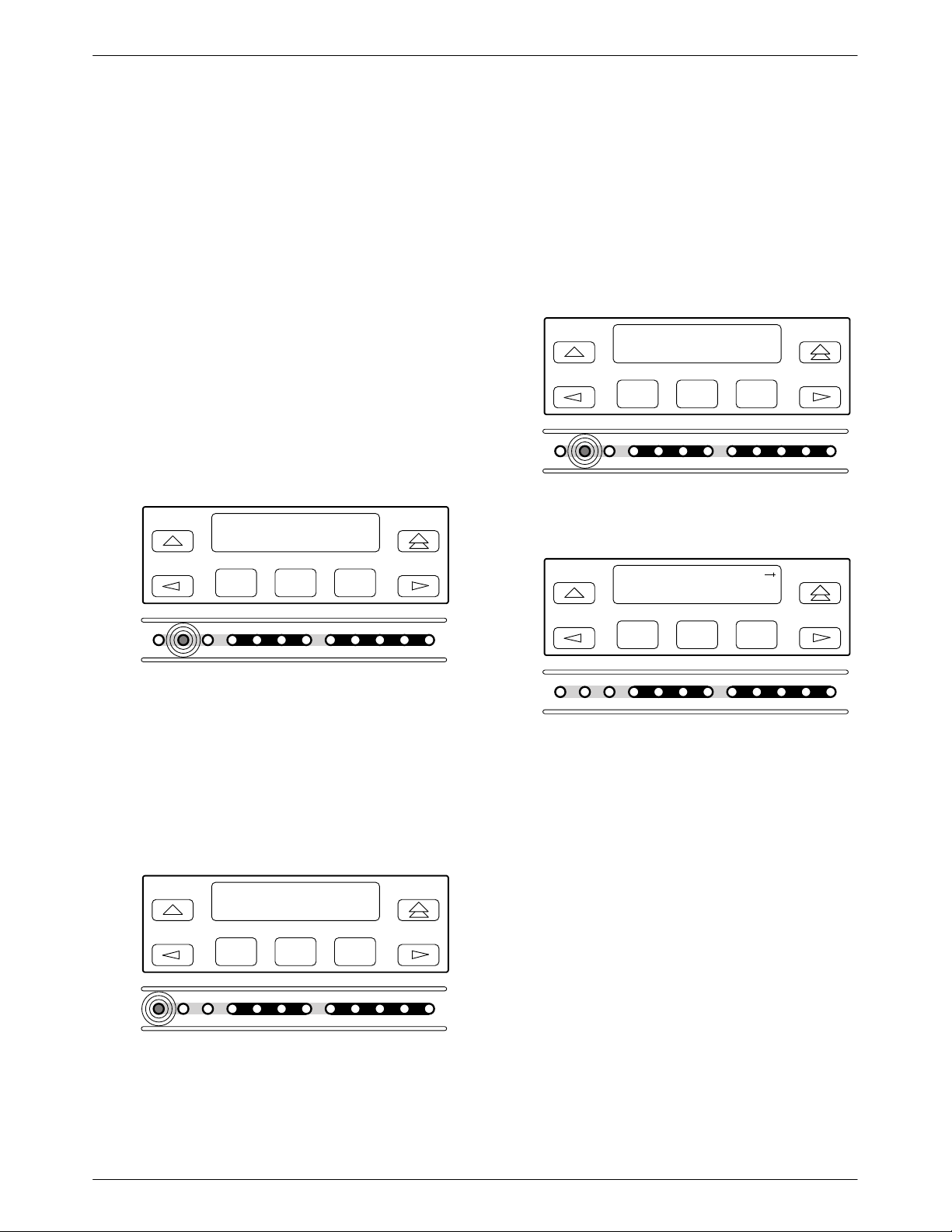
The scroll keys ( and ) serve one of two functions,
depending on whether a menu screen or a data entry
screen appears on the front panel.
For data entry screens, the
character to the left while the
key scrolls one
key scrolls one
character to the right.
For menu screens, the
menu choice while the
key scrolls to the previous
key scrolls to the next menu
choice.
If a choice is available to the left of the screen, the
character ← appears on the top line. If a choice is
available to the right of the screen, the → character
appears on the top line. If choices are available to both the
right and the left of the screen, two arrows appear (
).
The arrows indicate that you must use the scroll keys to
bring the additional options onto the screen.
F1 F2
F3
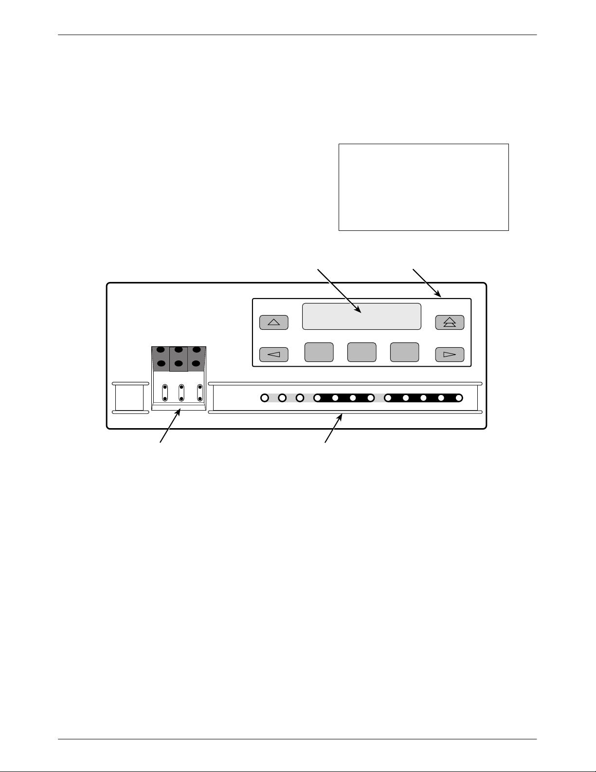
LEDs
There are twelve LEDs on the E1 NTU front panel.
The five LEDs on the right (Figure 3-5) are shared
between the G.703 DTE port and the data ports. Refer to
the Selecting the G.703 DTE or Data Port for LED
Display section later in this chapter to choose which port’s
status the LEDs display.
OK
FAIL
TEST SIG1 SIG2 OOF
Figure 3-5. E1 NTU LEDs
A green LED indicates normal operation. A yellow
LED indicates a warning (for the G.703 DTE port) or
activity (for the data ports). Conditions are sampled every
tenth of a second.
The twelve front panel LEDs are grouped into four
sections to indicate the status of the:
• System (T able 3-1 )
ALRM SIG ALRM PDVOOF BPV
NETWORK RXD
DTR TXD CTS RTS
495-1474
Test Jacks
Six test jacks are located on the front panel
(Figure 3-4). These are described in the Test Jacks section
in Chapter 4, Maintenance.
HDSL
NETE1LINEE1MON
Lp1
Lp2InOutInOut
495-1475
Figure 3-4. Test Jacks
• Network interface (T able 3-2 )
• G.703 DTE Port (Table 3-3)
• Data Ports (T able 3-4 )
3-4 December 1996 3360-A2-GB20-20
Page 26

Table 3-1
System LEDs
Operation
Name
OK Green Indicates the current operational state of the E1 NTU.
FAIL Yellow Indicates a system failure or a self-test.
TEST Yellow A system test is in progress.
Color Meaning
ON:
OFF:
BLINKING:
ON:
OFF:
BLINKING
ON:
OFF:
The E1 NTU is operational and has power.
The E1 NTU is performing a power-up self-test or a system failure
has occurred.
A software download is in progress.
A device error/fault is detected or a reset has just occurred.
No system failures are detected.
: A self-test is in progress.
A loopback or pattern test has been initiated either locally , by the
network, or externally.
No tests are active.
Table 3-2
Network Interface LEDs
Name
SIG1 Green Monitors the signal being received from the network.
SIG2 Green Monitors the signal being received from the network.
OOF Yellow Monitors Out Of Frame (OOF) conditions on the received network signal.
ALRM Yellow Indicates whether an alarm condition exists on the received network signal.
Color Meaning
ON:
OFF:
ON:
OFF:
ON
: At least one OOF was detected on the signal during the sampling
OFF:
ON:
OFF:
A recoverable signal is being received from the network on loop 1.
The signal cannot be recovered from the network on loop 1 (a Loss
of Signal condition exists).
A recoverable signal is being received from the network on loop 2.
The signal cannot be recovered from the network on loop 2 (a Loss
of Signal condition exists).
period.
No OOFs were detected on the signal during the sampling period.
An alarm condition (LOS, LOF, EER, RAI, AIS, RMA, MFA) exists on
the received network signal. Use the Device Health and Status
command to determine the alarm type.
No alarm condition exists on the network interface signal.
3-53360-A2-GB20-20 December 1996
Page 27

ACCULINK 336x E1 NTU
Table 3-3
G.703 DTE Port LEDs
Name
SIG Green Monitors the signal being received from the G.703 DTE port.
OOF Yellow Monitors Out Of Frame (OOF) conditions on the received G.703 DTE signal.
ALRM Yellow Indicates whether an alarm condition exists on the received G.703 DTE signal.
PDV Yellow Monitors Pulse Density Violations (PDV) on the received G.703 DTE signal.
BPV Yellow Monitors Bipolar Violations (BPV) on the received G.703 DTE signal.
Color Meaning
ON:
OFF:
ON:
OFF:
ON:
OFF:
ON
: At least one PDV was detected (and corrected) on the received
OFF:
ON:
OFF:
A recoverable signal is being received from the G.703 DTE port.
The signal cannot be recovered from the G.703 DTE port (a Loss of
Signal condition exists).
At least one OOF was detected on the signal during the sampling
period.
No OOFs were detected on the signal during the sampling period.
An alarm condition (LOS, LOF, EER, RAI, AIS, RMA, MFA) exists on
the received G.703 DTE signal. Use the Device Health and Status
command to determine the alarm type.
No alarm condition exists on the G.703 DTE Interface signal.
G.703 DTE signal during the sampling period.
No PDVs were detected on the received G.703 DTE signal during
the sampling period.
At least one BPV was detected (and corrected) on the received
G.703 DTE signal during the sampling period.
No BPVs were detected on the received G.703 DTE signal during
the sampling period.
3-6 December 1996 3360-A2-GB20-20
Page 28

Table 3-4
Data Port LEDs
Operation
Name
DTR Green Monitors the state of interchange circuit CD (CCITT 108/1, /2) – Data Terminal Ready
TXD Yellow Monitors activity on interchange circuit BA (CCITT 103) – Transmitted Data. This is the
RXD Yellow Monitors activity on interchange circuit BB (CCITT 104) – Received Data. This is data
CTS Yellow Monitors the state of interchange circuit CB (CCITT 106) – Clear-to-Send sent to the
Color Meaning
received from the synchronous data DTE.
ON:
OFF:
data sent from the synchronous data DTE to the data port on the E1 NTU.
ON:
OFF:
CYCLING:
sent to the synchronous data DTE from the data port on the E1 NTU.
ON:
OFF:
CYCLING:
synchronous data DTE.
ON:
OFF:
DTR is being asserted by the synchronous data DTE.
DTR is not being asserted.
Ones are being received from the synchronous data DTE.
Zeros are being received from the synchronous data DTE.
Both ones and zeros are being received from the synchronous
data DTE.
Ones are being sent to the synchronous data DTE.
Zeros are being sent to the synchronous data DTE.
Both ones and zeros are being sent to the synchronous data DTE.
CTS is being asserted by the E1 NTU.
CTS is not being asserted.
RTS Yellow Monitors the state of interchange circuit CA (CCITT 105) – Request-to-Send received
from the synchronous data DTE.
ON:
OFF:
RTS is being asserted by the synchronous data DTE.
RTS is not being asserted.
3-73360-A2-GB20-20 December 1996
Page 29

ACCULINK 336x E1 NTU
Displaying Unit Identity
The identity of the E1 NTU (serial number, model
number, software revision level, hardware revision level,
and customer identification) is available through the
Status branch of the front panel menu (see Appendix A,
Front Panel Menu).
The customer identification is the only identity number
you can change.
To display the E1 NTU’s identity (ID),
1. From the top-level menu screen, select Stat.
E1 HDSL NTU
Stat Test Cnfig
F1
F2
2. From the Status screen, press the key until the
ID selection appears on the screen.
F3
4. The following screens appear in the order listed
each time you press the
key.
Identity:
xxxxxxx
Ser=
F1
F2
F3
Identity:
xxxx-xx-xxx
Mod=
F1
F2
F3
Identity:
Cust ID=
F1
xxxxxxxx
F2
F3
3. Select ID.
Status:
HDSL DevHS STest
F1
F2
F3
Status:
TStat LED ID
F1
F2
F3
Identity:
SRev=
F1
Identity:
CCA1=
F1
Identity:
CCA2=
F1
Identity:
CCA3=
xx.xx.xx
F2
xxxx-xxx
F2
xxxx-xxx
F2
xxxx-xxx
F3
F3
F3
F1
3-8 December 1996 3360-A2-GB20-20
F2
F3
Page 30
Operation
To change the customer identification (CID),
1. From the top-level menu, press the
key until
the Ctrl selection appears on the screen.
E1 HDSL NTU
Stat Test Cnfig
F1
F2
F3
2. Select Ctrl.
E1 HDSL NTU
Test Cnfig Ctrl
F1
F2
F3
3. From the Control screen, press the key until
the CID selection appears on the screen.
Control:
Rel LED ClrReg
4. Select CID.
Control:
Reset CID DL
F1
F2
F3
5. Use the and keys to position the cursor
under the desired character. You must enter a
character before the
moves the cursor to the
next space to the right.
CustID:
xxxxxxxx
Up Down Save
F1
F2
F3
6. Enter the desired ID. Press F1 (Up) and F2
(Down) to scroll up and down through the valid
characters/numbers for the customer ID. Valid
characters are 0 through 9, #, -, ., /, A to Z, and
blank space. Press F3 (Save) to save the ID.
F1
F2
F3
CustID:
xxxxxxxx
Up Down Save
F1
F2
F3
3-93360-A2-GB20-20 December 1996
Page 31

ACCULINK 336x E1 NTU
Displaying LED Conditions
The same conditions monitored by the front panel
LEDs can also be monitored by the LED command. This
command is most useful when the E1 NTU is being
accessed remotely (see Appendix G, Front Panel
Emulation). When using Front Panel Emulation, no LEDs
are shown on the PC’s screen; you must use the Stat
command procedure described below to get LED
information.
NOTE
The following procedure is an
example only. Screen displays
may vary depending on the
model of the E1 NTU.
To display LED conditions on the front panel screen,
1. From the top-level menu screen, select Stat.
4. From the Select LEDs screen, press the Function
key that corresponds to E1 or the port for which
you want to display LEDs. Use the scroll keys, if
necessary.
Select LEDs:
E1 Prt1 Prt2
F1
F2
F3
If you chose E1, the LED Display screen lists the
LED signals, two at a time, on the second line. A
vertical bar at the left of the LED name indicates
the condition is ON, while an underscore indicates
the condition is Off.
LED Display:
_Test _NetSig1
F1
F2
F3
E1 HDSL NTU
Stat Test Cnfig
F1
F2
F3
2. From the Status screen, press the key until the
LED selection appears on the screen.
Status:
HDSL DevHS STest
F1
F2
F3
3. From the Status screen, select LED.
Status:
Perf TStat LED
F1
F2
F3
If you chose a port, the Port n LEDs screen lists
the LED signals, two at a time, on the second line.
A vertical bar at the left of the LED name
indicates the condition is ON, while an underscore
indicates the condition is Off.
Port n LEDs:
_DTR _TXD
F1
F2
F3
5. Use the and keys to scroll LED names
onto the screen.
3-10 December 1996 3360-A2-GB20-20
Page 32

Operation
Selecting the G.703 DTE or
Data Port for LED Display
Use the LED command on the Control branch to select
which port’s (G.703 DTE or data port) status appears on
the five shared LEDs on the front panel.
NOTE
The following procedure is an
example only. Screen displays
may vary depending on the
model and configuration of the
E1 NTU.
To select a port for LED display,
1. From the top-level menu screen, press the
until the Ctrl selection appears on the screen.
E1 HDSL NTU
Stat Test Cnfig
F1
F2
F3
key
The currently selected port name appears on the
top line of the LCD. DTE indicates the G.703
DTE port.
LED Dsply: DTE
DTE Prt1 Prt2
F1
F2
F3
4. From the LED Dsply screen, press the Function
key that corresponds to the G.703 DTE or data
port for which you want the LEDs to display. Use
the scroll keys, if necessary.
Select DTE to monitor the G.703 DTE port’s SIG,
OOF, ALRM, PDV, and BPV status signals on the
shared LEDs.
Select a particular data port to monitor the data
port’s DTR, TXD, RXD, CTS, and RTS control
signals on the shared LEDs.
Changing Configuration
Options
2. Select Ctrl.
E1 HDSL NTU
Test Cnfig Ctrl
F1
F2
F3
3. From the Control screen, select LED.
Control:
Rel LED ClrReg
F1
F2
F3
The E1 NTU is an intelligent device that displays only
valid options for the current configuration. Therefore, you
are only presented with menu choices that are consistent
with the current configuration and operational state of the
E1 NTU; invalid combinations of configuration options
do not appear. For example, menus displayed for the
Model 3360 (2 ports) and the Model 3364 (4 ports) differ
due to the number of ports available. Also, if the G.703
DTE interface selection is disabled, many of the menu
choices do not appear. Be aware that although all options
are shown in this guide, what you see on your E1 NTU
varies with your configuration.
The E1 NTU offers four sets of configuration options
located in the following memory areas:
• Active (Activ). The configuration option set active
for the E1 NTU is stored here. Before a
configuration option set becomes active for the E1
NTU, you must save the set to the Active area.
When the E1 NTU is shipped from the factory, the
Active configuration option set is identical to the
Factory set. This area can be written to and controls
the current operation of the device.
3-113360-A2-GB20-20 December 1996
Page 33

ACCULINK 336x E1 NTU
• Customer 1 (Cust1). The first of two sets of
customer-defined configuration options. This area
can be written to.
• Customer 2 (Cust2). The second of two sets of
customer-defined configuration options. This area
can be written to.
• Factory (Fact). This is a set of configuration
options preset at the company. This set is
determined by what is considered to be the most
common configuration used in the E1 NTU market.
Factory options are read-only.
The configuration options are divided into functional
groups. Appendix C contains a list of the configuration
options and defaults. These groups are:
• DTE (G.703) Interface
• Port
• Network Interface
• Channel
• General
• User Interface
2. Select the configuration option set to be copied
into the Edit area by using the appropriate
Function key. Use the scroll keys, if necessary.
Load from:
Activ Cust1
F1
F2
F3
3. Select Edit.
Choose Funct:
Edit Save
F1
F2
F3
4. From the Edit screen, select the functional group
you want to edit by pressing the appropriate
Function key. Use the scroll keys, if necessary.
(The NET selection is shown as an example only.)
• Alarm
• General SNMP
• SNMP Trap
Use the Configuration (Cnfig) branch of the front panel
menu tree to display or change E1 NTU configuration
options (see Appendix A, Front Panel Menu).
Displaying/Editing Configuration Options
To display/edit configuration options,
1. From the top-level menu screen, select Cnfig.
E1 HDSL NTU
Stat Test Cnfig
F1
F2
F3
Edit:
DTE Port NET
F1
F2
F3
The configuration options for the selected
functional group appear on the front panel one
option at a time. The option name appears on
Line 1 with the current value next to it. T o reach
other options, use the Next and Previous selections
to scroll forward and backward through the group
of options.
HDSL Mode:NTU
Next NTU LTU
F1
F2
F3
5. Press the appropriate Function key to choose
another value. Use the scroll keys, if necessary.
6. Use the Save procedure to save your changes to
the Active or Customer area.
3-12 December 1996 3360-A2-GB20-20
Page 34

Operation
Saving Edit Changes
Save edit changes to the Active area when you want
those changes to take effect immediately. Save edit
changes to the Customer area when you want to overwrite
the existing Customer configuration options and store
these changes for future use.
NOTE
If you attempt to exit the Edit
function after making changes
without performing a Save, the E1
NTU prompts you with Save
Options? Choose Yes or No.
To save edit changes,
1. From the Choose Function screen (one level above
the Edit screen, two levels below the top-level
menu screen), select Save.
Choose Funct:
Edit Save
F1
F2
F3
Selecting/Copying to a Specific Port
For the E1 NTU, you have the capability of selecting a
specific port to configure, and then (for 2-port and 4-port
E1 NTUs) copying the configuration options from that
port to another port (or to all ports).
NOTE
The following procedure is an
example only. Screen displays
may vary depending on the
model and configuration of the
E1 NTU.
To select a specific port to configure,
1. From the top-level menu screen, select Cnfig.
2. Select the configuration option set to be copied
into the Edit area by using the appropriate
Function key. Use the scroll keys, if necessary.
3. Select Edit.
4. From the Edit screen, select Port.
2. Choose whether you want to save to the Active,
Customer 1, or Customer 2 area. Use the scroll
keys, if necessary.
Save Edit to:
Activ Cust1
F1
F2
F3
Edit:
DTE Port NET
F1
F2
F3
5. From the Port Select screen, press the Function
key that corresponds to the port you want to
configure. Use the
key to scroll addition ports
onto the screen, if necessary. Configure the port
(see Appendix C, Configuration Options).
Port Select:
Copy Prt1 Prt2
F1
F2
F3
3-133360-A2-GB20-20 December 1996
Page 35

ACCULINK 336x E1 NTU
To copy the configuration options to one or all ports,
6. From the Port Select screen, select Copy.
Port Select:
Copy Prt1 Prt2
F1
F2
F3
7. Select the port from which you want to copy the
configuration options using the corresponding
Function key.
Copy From:
Prt1 Prt2 Prt3
F1
F2
F3
8. Select the port to which you want to copy the
configuration options using the corresponding
Function key . Or, press F1 (All) to choose to copy
to all ports.
• Specify the two community names that are allowed
to access the device’s Management Information
Base (MIB).
• Configure the device to send traps to the SNMP
manager, if desired.
Selecting the Port
The SNMP manager or network device (e.g., a router)
can be directly connected to the communications (COM)
port. An external LAN Adapter can be connected to either
the COM port or the auxiliary (AUX) port to provide
Ethernet or T oken Ring connectivity. Also, the E1 NTU
can be daisy chained together by connecting the COM
port of one device to the AUX port of the other, providing
SNMP connectivity.
The COM port can support either synchronous or
asynchronous PPP, or asynchronous SLIP at data rates of
up to 38,400 bps. The AUX port can support data rates up
to 38,400 bps.
The example shown below assumes that the COM port
is being used as the link to the SNMP manager.
To select the COM port as the management link,
1. From the top-level menu screen, select Cnfig.
Copy To:
All Prt1 Prt2
F1
F2
F3
Configuring the E1 NTU for
SNMP Management
To configure the E1 NTU for management by an
SNMP management system you must,
• Select and configure the port that provides the link
to the SNMP management system.
• Set the Internet Protocol (IP) address and subnet
mask needed to access the device (see Appendix F,
IP Network Addressing Scenario).
• Select the link layer protocol (PPP or SLIP) for the
port.
2. Select the configuration option set to be copied
into the Edit area by using the appropriate
Function key. Use the scroll keys, if necessary.
3. Select Edit.
4. From the Edit screen, press the
key until the
User selection appears on the screen.
5. Select User.
Edit:
Chan Gen User
F1
F2
F3
6. Press F1 (Next) until the Com Use configuration
option appears.
3-14 December 1996 3360-A2-GB20-20
Page 36

Operation
7. Select SNMP to configure the COM port as the
management link to an external SNMP manager.
Com Use:
Next SNMP ASCII
F1
F2
F3
Setting the IP Address
The IP address is the address used by the SNMP
manager to access the device. For devices using PPP, the
IP address can be negotiated if the network device (e.g.,
router or SNMP manager) supports such negotiation. The
IP address is composed of four fields with three digits per
field (xxx.xxx.xxx.xxx).
The IP address is set for the COM port or the AUX
port (with LAN Adapter or daisy chain), depending on
which one has been chosen as the SNMP communications
link. The example below assumes that an IP address of
010.155.111.222 is being set for the COM port. You can
use the same principles to assign any value (between 000
and 255 for each digit field) to either port.
To assign an IP address to the COM port,
6. From the SNMP Config screen, select Gen.
SNMP Config:
Gen Trap
F1
F2
F3
7. Press F1 (Next) until the Com IP Adr
configuration option appears.
NOTE
Steps 8 and 9 describe the
process for entering the Com IP
address. This process applies to
any IP address.
8. Press F2 (Edit) to edit the IP address. You have the
option of using F3 (Clear) to reset the IP address
to the factory default 000.000.000.000.
Com IP Adr:
Next Edit Clear
1. From the top-level menu screen, select Cnfig.
2. Select the configuration option set to be copied
into the Edit area by using the appropriate
Function key. Use the scroll keys, if necessary.
3. Select Edit.
4. From the Edit screen, press the
key until the
SNMP selection appears on the screen.
5. Select SNMP.
Edit:
User Alarm SNMP
F1
F2
F3
F1
F2
F3
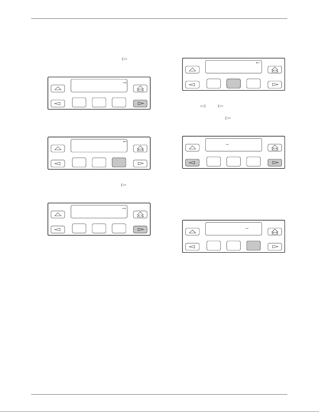
9. Use the and keys to position the cursor
under the digit you want to change. Press F1 (Up)
to increment the digit or F2 (Down) to decrement
the digit. In this example, you would press
once to place the cursor under the middle digit in
the first digit field, then press F1 (Up) once to
change the 0 to a 1. Continue in this manner to
change the other digits.
000.000.000.000
Up Down Save
F1
F2
F3
3-153360-A2-GB20-20 December 1996
Page 37

ACCULINK 336x E1 NTU
10. When you are through changing the IP address,
you must press F3 (Save) to save the value.
Otherwise, the original value will be retained.
010.155.111.222
Up Down Save
F1
F2
F3
Selecting the Link Layer Protocol
Two link layer protocols, Point-to-Point Protocol (PPP)
and Serial Line Internet Protocol (SLIP), are supported for
connection to an external SNMP manager or network
device (e.g., a router). PPP can be used for synchronous or
asynchronous operation. SLIP can be used for
asynchronous operation only.
The E1 NTU implementation of PPP supports the
following:
• Full negotiation of PPP’s Link Control Protocol
(LCP).
To select the link layer protocol,
1. From the top-level menu screen, select Cnfig.
2. Select the configuration option set to be copied
into the Edit area by using the appropriate
Function key. Use the scroll keys, if necessary.
3. Select Edit.
4. From the Edit screen, press the
key until the
SNMP selection appears on the screen.
5. Select SNMP.
Edit:
User Alarm SNMP
F1
F2
F3
6. From the SNMP Config screen, select Gen.
• Active negotiation of LCP when the connection is
established.
• Maximum Request Unit (MRU) sizes up to
1500 bytes, but the E1 NTU will attempt to
negotiate down to 500 bytes.
• The E1 NTU provides a unique LCP magic number
derived from the unit serial number and the elapsed
time.
• Full negotiation of escape characters.
The E1 NTU implementation of PPP does not support
Link Quality Reports (LQR), compression, encryption,
Password Authentication Protocol (PAP) or Challenge
Authentication Protocol (CHAP).
The E1 NTU implementation of SLIP supports a fixed
MRU size of 1006 bytes.
Before selecting the protocol, you must first select the
port to be used as the communications link. Refer to the
Selecting the Port section on page 3-14. This example
assumes that the COM port is being used as the
communications link.
SNMP Config:
Gen Trap
F1
F2
F3
7. Press F1 (Next) until the Com Link configuration
option appears.
8. Press F2 (PPP) or F3 (SLIP).
Com Link:
Next PPP SLIP
F1
F2
F3
3-16 December 1996 3360-A2-GB20-20
Page 38

Operation
Specifying the Community Name(s) and
Access Type(s)
You have the capability of specifying up to two
community names (community name 1 and community
name 2) to be used by external SNMP managers when
trying to access objects in the E1 NTU’s MIB. Once you
specify the community name(s), you must then specify the
type of access to the MIB that SNMP managers in the
community are permitted to have.
To specify the community name 1 and its access type,
1. From the top-level menu screen, select Cnfig.
2. Select the configuration option set to be copied
into the Edit area by using the appropriate
Function key. Use the scroll keys, if necessary.
3. Select Edit.
4. From the Edit screen, press the
SNMP selection appears on the screen.
5. Select SNMP.
key until the
8. Press F2 (Edit) to edit the community name. The
factory default community name is public.
CommunityName1:
Next Edit Clear
F1
F2
F3
NOTE
Steps 9 and 10 describe the
process for entering text strings
for SNMP configuration options.
This process applies to entering
any text strings into SNMP
configuration options.
9. Use the and keys to position the cursor
under the character you want to change. Press
F1 (Up) or F2 (Down) to scroll through the valid
numbers/characters for the text string.
Edit:
User Alarm SNMP
F1
F2
F3
6. From the SNMP Config screen, select Gen.
SNMP Config:
Gen Trap
F1
F2
F3
7. Press F1 (Next) until the CommunityName1
configuration option appears.
public
Up Down Save
F1
F2
F3
The F1 (Up) key scrolls through the ASCII
character set in the following order: numbers
(0–9), lowercase letters (a–z), uppercase letters
(A–Z), space character, ASCII symbols (ascending
order, based on ASCII code), and the End of Line
symbol (←). The ← erases all characters to the
right of the cursor.
10. When you are through changing the community
name, you must press F3 (Save) to save the value.
Otherwise, the original value will be retained.
3-173360-A2-GB20-20 December 1996
Page 39

ACCULINK 336x E1 NTU
11. Press F1 (Next) until the Access 1 configuration
option appears.
12. Press F2 (Read) or F3 (R/W).
Access 1:
Next Read R/W
F1
F2
F3
The Read selection allows read-only access
(SNMP “Get”) to the accessible objects in the
MIB when community name 1 is used. The R/W
selection allows Read/Write access (SNMP “Get”
and “Set”) to the objects in the MIB. Write access
is allowed for all objects specified as read/write in
the MIB. Read access is allowed for all objects
specified as read-only or read/write.
Configuring SNMP Traps
A trap is an unsolicited message that is sent from the
E1 NTU to an SNMP manager when the device detects
certain, pre-specified conditions. These traps enable the
SNMP manager to monitor the state of the network.
The SNMP Trap configuration option must be enabled
for trap messages to be sent over the communications
link. You must specify the number of SNMP managers
that are to receive traps from this device, an IP address for
each SNMP manager specified, and the type of traps to be
sent from this device. For more information, refer to
Appendix C, Configuration Options, and the SNMP Traps
section in Chapter 4, Maintenance.
Enabling SNMP Trap Messages
To enable SNMP trap messages from this device,
1. From the top-level menu screen, select Cnfig.
2. Select the configuration option set to be copied
into the Edit area by using the appropriate
Function key. Use the scroll keys, if necessary.
3. Select Edit.
4. From the Edit screen, press the
Alarm selection appears on the screen.
5. Select Alarm.
Edit:
User Alarm SNMP
F1
F2
6. Press F1 (Next) until the SNMP Trap
configuration option appears.
7. Press F2 (Enab) to enable trap messages over the
SNMP management link.
SNMP Trap:
Next Enab Disab
F1
F2
key until the
F3
F3
3-18 December 1996 3360-A2-GB20-20
Page 40

Operation
Selecting the Number of Trap Managers
If you intend to issue traps to an SNMP manager(s)
from this device, you must specify the number of SNMP
managers that are to receive the traps.
To specify the number of SNMP managers to receive
traps from this device,
1. From the top-level menu screen, select Cnfig.
2. Select the configuration option set to be copied
into the Edit area by using the appropriate
Function key. Use the scroll keys, if necessary.
3. Select Edit.
4. From the Edit screen, press the
SNMP selection appears on the screen.
5. Select SNMP.
Edit:
User Alarm SNMP
F1
F2
key until the
F3
Configuring a Destination for SNMP Traps
A destination must be configured for each SNMP trap
manager specified. This configuration option is displayed
for the number of trap managers specified by the Number
of Trap Managers configuration option.
To configure an IP address for the SNMP trap
manager,
1. From the top-level menu screen, select Cnfig.
2. Select the configuration option set to be copied
into the Edit area by using the appropriate
Function key. Use the scroll keys, if necessary.
3. Select Edit.
4. From the Edit screen, press the
SNMP selection appears on the screen.
5. Select SNMP.
Edit:
User Alarm SNMP
F1
F2
key until the
F3
6. From the SNMP Config screen, select Trap.
SNMP Config:
Gen Trap
F1
F2
F3
7. Select the number of SNMP managers to receive
traps (from 1 through 6) by using the appropriate
Function key. Use the scroll keys, if necessary.
Num Trap Mgrs:1
Next 1 2
F1
F2
F3
6. From the SNMP Config screen, select Trap.
SNMP Config:
Gen Trap
F1
F2
F3
7. Press F1 (Next) until the Trapn IP Address
configuration option appears.
8. Press F2 (Edit) to edit the IP address. You have the
option of using F3 (Clear) to reset the IP address
to the factory default 000.000.000.000. Refer to
the Setting the IP Address section on page 3-15 for
more information on setting an IP address.
3-193360-A2-GB20-20 December 1996
Page 41

ACCULINK 336x E1 NTU
9. Press F1 (Next) until the Trapn Destination
configuration appears, and select the destination
for the SNMP trap by using the appropriate
Function key. Use the scroll keys, if necessary.
Trapn Dst:
Next None Com
F1
F2
F3
Configuring DS0 Channels
The E1 NTU provides channel configuration options
that allow you to do the following:
• Display the DS0 assignments for the network,
G.703 DTE, and data port interfaces.
• Allocate DS0 channels on the G.703 DTE interface
to the network interface.
• Allocate DS0 channels on the network or G.703
DTE interface to particular data ports.
NOTE
If TS16 is reserved for CCS, D16
will automatically be assigned to
N16, and the G.703 DTE DS0
channels allocated to the network
must be directly connected to the
corresponding channel (e.g., D1
to N1, D2 to N2, etc.).
To allocate DS0 channels, begin by defining the logical
channel configuration for the network interface, and then
the G.703 DTE interface, and then any ports, if desired.
See Figures 3-6 and 3-8 for examples of conceptual
diagrams of channel configurations.
NOTE
With the exception of time-slot 16,
a CAS allocation example is the
same as the example in Figures
3-8 and 3-9. TS16, however, is
directly connected when using
CAS (D16 to N16).
• Specify whether time-slot 16 (TS16) is available for
data or reserved for signaling information using
Common-Channel Signaling (CSS) or
Channel-Associated Signaling (CAS).
NOTE
CCS is typically used in a 2-frame
multiframe system, whereas CAS
is used in a 16-frame system.
• Clear (deallocate) all DS0 channels from the
network, G.703 DTE, or data port interface.
• Map data from one port to another.
Blank configuration worksheets are provided at the
back of Appendix C, Configuration Options. To complete
the configuration worksheets for DS0 channel allocation:
1. Complete the Network Interface and the G.703
DTE Interface tables (unless the G.703 DTE
interface is disabled) as shown in the examples in
Figures 3-7 and 3-9.
2. Using the worksheets shown in Figures 3-10
and 3-11, circle the configuration options needed
to implement the logical channel configuration.
Once you have completed the worksheets, enter this
information using the procedures in the Allocating Data
Ports section on page 3-28. Configuration options are
listed in Appendix C.
3-20 December 1996 3360-A2-GB20-20
Page 42

NETWORK INTERFACE
N1
N2
N3
N4
N5
N6
N7
N8
N9
N10
N11
N12
N13
N14
N15
N16
N17
N18
N19
N20
N21
N22
N23
N24
N25
N26
N27
N28
N29
N30
N31
(N1-D1, N2-D2, ETC.)
AUTOMA TIC ALLOCA TION
Operation
G.703 DTE INTERFACE
D1
D2
D3
D4
D5
D6
D7
D8
D9
D10
D11
D12
D13
D14
D15
D16
D17
D18
D19
D20
D21
D22
D23
D24
D25
D26
D27
D28
D29
D30
D31
PORTS
PRT 1
PRT 2
PRT 3
PRT 4
496-14880
Figure 3-6. Example of Channel Allocation with TS16 Reserved for Common-Channel Signaling
3-213360-A2-GB20-20 December 1996
Page 43

ACCULINK 336x E1 NTU
Network Interface
Network Channel
N1
N2
N3
N4
N5
N6
N7
N8
N9
N10
N11
N12
N13
N14
N15
N16
N17
N18
N19
N20
N21
N22
N23
N24
N25
N26
N27
N28
N29
N30
N31
Allocations
D1 – D31 indicates allocation to DTE
(G.703) channels.
D1
D2
D3
D4
D5
D10
D1 1
D12
D13
D16
Prt1
Prt1
Prt3
Prt2
Prt2
Prt2
Prt2
Prt2
Prt2
Prt3
Allocation
G.703 DTE Interface
G.703 Channel
D1
D2
D3
D4
D5
D6
D7
D8
D9
D10
D11
D12
D13
D14
D15
D16
D17
D18
D19
D20
D21
D22
D23
D24
D25
D26
D27
D28
D29
D30
D31
Allocations
N1 – N31 indicates allocation to network
channels.
N1
N2
N3
N4
N5
N10
N11
N12
N13
N16
Allocation
Prt1 – Prt4 indicates allocation to
synchronous data ports.
Figure 3-7. Example of Interface Worksheet with TS16 Reserved for Common Channel Signaling
3-22 December 1996 3360-A2-GB20-20
Page 44

NETWORK INTERFACE
N1
N2
N3
N4
N5
N6
N7
N8
N9
N10
N11
N12
N13
N14
N15
N16
N17
N18
N19
N20
N21
N22
N23
N24
N25
N26
N27
N28
N29
N30
N31
Operation
G.703 DTE INTERFACE
D1
D2
D3
D4
D5
D6
D7
D8
D9
D10
D11
D12
D13
D14
D15
D16
D17
D18
D19
D20
D21
D22
D23
D24
D25
D26
D27
D28
D29
D30
D31
PORTS
PRT 1
PRT 2
PRT 3
PRT 4
496-14879
Figure 3-8. Example of Channel Allocation with TS16 Available for Data
3-233360-A2-GB20-20 December 1996
Page 45

ACCULINK 336x E1 NTU
Network Interface
Network Channel
N1
N2
N3
N4
N5
N6
N7
N8
N9
N10
N11
N12
N13
N14
N15
N16
N17
N18
N19
N20
N21
N22
N23
N24
N25
N26
N27
N28
N29
N30
N31
Allocations
D1 – D31 indicates allocation to DTE
(G.703) channels.
D1
D2
D3
D4
D5
D10
D1 1
D12
D13
D16
Prt1
Prt1
Prt1
Prt3
Prt2
Prt2
Prt2
Prt2
Prt2
Prt2
Prt3
Allocation
G.703 DTE Interface
G.703 Channel
D1
D2
D3
D4
D5
D6
D7
D8
D9
D10
D11
D12
D13
D14
D15
D16
D17
D18
D19
D20
D21
D22
D23
D24
D25
D26
D27
D28
D29
D30
D31
Allocations
N1 – N31 indicates allocation to network
channels.
N1
N2
N3
N4
N6
N10
N11
N12
N13
N14
Allocation
Prt1 – Prt4 indicates allocation to
synchronous data ports.
Figure 3-9. Example of Interface Worksheet with TS16 Available for Data
3-24 December 1996 3360-A2-GB20-20
Page 46

Operation
Port Chan
Conf
Port 1
Port 2
Options Value
Assign To NET, DTE, Prt2, Prt3, Prt4
Assign By Block, Chan
Port Rate Nx64: 64, 128, 192, 256, 320, 384, 448, 512, 576,
640, 704, 768, 832, 896, 960, 1024, 1088, 1 152,
1216, 1280, 1344, 1408, 1472, 1536, 1600, 1664,
1728, 1792, 1856, 1920, 1984
If Assign By Block
Start At Time Slot (Nn or Dn): 1, 2, 3, 4, 5, 6, 7, 8, 9, 10, 1 1,
If Assign By Chan Time Slot (Nn or Dn): 1, 2, 3, 4, 5, 6, 7, 8, 9, 10, 1 1,
Assign To NET, DTE, Prt1, Prt3, Prt4
Assign By Block, Chan
Port Rate Nx64: 64, 128, 192, 256, 320, 384, 448, 512, 576,
If Assign By Block
NOTE: If time-slot 16 is reserved for signaling, the
highest port rate (1984) does not appear.
12, 13, 14, 15, 16, 17, 18, 19, 20, 21, 22, 23, 24, 25,
26, 27, 28, 29, 30, 31 (Select One)
12, 13, 14, 15, 16, 17, 18, 19, 20, 21, 22, 23, 24, 25,
26, 27, 28, 29, 30, 31 (Select Multiple)
640, 704, 768, 832, 896, 960, 1024, 1088, 1 152,
1216, 1280, 1344, 1408, 1472, 1536, 1600, 1664,
1728, 1792, 1856, 1920, 1984
NOTE: If time-slot 16 is reserved for signaling, the
highest port rate (1984) does not appear.
Start At Time Slot (Nn or Dn): 1, 2, 3, 4, 5, 6, 7, 8, 9, 10, 1 1,
12, 13, 14, 15, 16, 17, 18, 19, 20, 21, 22, 23, 24, 25,
26, 27, 28, 29, 30, 31 (Select One)
If Assign By Chan Time Slot (Nn or Dn): 1, 2, 3, 4, 5, 6, 7, 8, 9, 10, 1 1,
12, 13, 14, 15, 16, 17, 18, 19, 20, 21, 22, 23, 24, 25,
26, 27, 28, 29, 30, 31 (Select Multiple)
Figure 3-10. Port Channel Configuration Worksheet (Ports 1 and 2)
3-253360-A2-GB20-20 December 1996
Page 47

ACCULINK 336x E1 NTU
Port Chan
Conf
Port 3
Port 4
Options Value
Assign To NET, DTE, Prt1, Prt2, Prt4
Assign By Block, Chan
Port Rate Nx64: 64, 128, 192, 256, 320, 384, 448, 512, 576,
640, 704, 768, 832, 896, 960, 1024, 1088, 1 152,
1216, 1280, 1344, 1408, 1472, 1536, 1600, 1664,
1728, 1792, 1856, 1920, 1984
If Assign By Block
Start At Time Slot (Nn or Dn): 1, 2, 3, 4, 5, 6, 7, 8, 9, 10, 1 1,
If Assign By Chan Time Slot (Nn or Dn): 1, 2, 3, 4, 5, 6, 7, 8, 9, 10, 1 1,
Assign To NET, DTE, Prt1, Prt2, Prt3
Assign By Block, Chan
Port Rate Nx64: 64, 128, 192, 256, 320, 384, 448, 512, 576,
If Assign By Block
NOTE: If time-slot 16 is reserved for signaling, the
highest port rate (1984) does not appear.
12, 13, 14, 15, 16, 17, 18, 19, 20, 21, 22, 23, 24, 25,
26, 27, 28, 29, 30, 31 (Select One)
12, 13, 14, 15, 16, 17, 18, 19, 20, 21, 22, 23, 24, 25,
26, 27, 28, 29, 30, 31 (Select Multiple)
640, 704, 768, 832, 896, 960, 1024, 1088, 1 152,
1216, 1280, 1344, 1408, 1472, 1536, 1600, 1664,
1728, 1792, 1856, 1920, 1984
NOTE: If time-slot 16 is reserved for signaling, the
highest port rate (1984) does not appear.
Start At Time Slot (Nn or Dn): 1, 2, 3, 4, 5, 6, 7, 8, 9, 10, 1 1,
12, 13, 14, 15, 16, 17, 18, 19, 20, 21, 22, 23, 24, 25,
26, 27, 28, 29, 30, 31 (Select One)
If Assign By Chan Time Slot (Nn or Dn): 1, 2, 3, 4, 5, 6, 7, 8, 9, 10, 1 1,
12, 13, 14, 15, 16, 17, 18, 19, 20, 21, 22, 23, 24, 25,
26, 27, 28, 29, 30, 31 (Select Multiple)
Figure 3-11. Port Channel Configuration Worksheet (Ports 3 and 4)
3-26 December 1996 3360-A2-GB20-20
Page 48

Operation
NOTE
The following procedures are
examples only. Screen displays
may vary depending on the
model and configuration of the
E1 NTU.
Displaying DS0 Channel Assignments
Use the Display command (in the Channel
Configuration branch) to view how the DS0 channels are
currently allocated.
Line 1 of the display shows the 31 channels of the
selected interface. Pressing the
channels onto the screen in groups of three. Line 2
displays what is allocated to the DS0 channel listed in
Line 1. Symbols used in the display are shown in
Table 3-5 .
Table 3-5
Display Channel Symbols
Symbol
– The DS0 channel is not allocated.
or key scrolls the
Meaning
3. Select Edit.
4. From the Edit screen, press the
key until the
Chan selection appears on the screen.
5. Select Chan.
Edit:
Port NET Chan
F1
F2
F3
6. From the Channel Config screen, select Dsply
(display).
Channel Config:
Dsply Clear DTE
F1
F2
F3
7. From the Display Chan screen, select NET to
display the channels allocated to the network
interface.
Prt
n
N
n
D
n
The DS0 channel is allocated to Port n,
where n is 1, 2, 3, or 4.
The DS0 channel is allocated to the
network interface DS0 channel
n
can be any number from 1 through 31.
The DS0 channel is allocated to the
G.703 DTE interface DS0 channel n,
where
n
can be any number from 1
through 31.
To display the DS0 channel allocation,
1. From the top-level menu screen, select Cnfig.
2. Select the configuration option set to be copied
into the Edit area by using the appropriate
Function key. Use the scroll keys, if necessary.
n
, where
Display Chan:
NET DTE Ports
F1
F2
F3
Or, select DTE to display the channels allocated to
the G.703 DTE interface.
Display Chan:
NET DTE Ports
F1
F2
F3
3-273360-A2-GB20-20 December 1996
Page 49

ACCULINK 336x E1 NTU
8. If you selected NET the channels allocated to the
network interface are displayed. Line 1 displays
the 31 channels for the network interface, while
Line 2 displays what is allocated to the DS0
channel shown in Line 1. Pressing the
or
key scrolls the channels onto the screen in groups
of three.
N1 N2 N3
D2 D3 Prt1
F1
F2
F3
If you selected DTE, the channels allocated to the
G.703 DTE interface are displayed. Line 1
displays the 31 channels for the G.703 DTE
interface, while Line 2 displays what is allocated
to the DS0 channel shown in Line 1.
D1 D2 D3
–N1N2
Once a port is selected, you have access to the
configuration options to complete the port allocation
procedure. These configuration options enable you to,
• Assign the selected port to the desired interface
• Select the desired method for channel allocation
• Select the port rate and starting channel (if the
allocation method is block)
• Select the specific channels (if the allocation
method is by individual channel)
These configuration options are explained in detail in
Appendix C.
To select the data port,
1. From the top-level menu screen, select Cnfig.
2. Select the configuration option set to be copied
into the Edit area by using the appropriate
Function key. Use the scroll keys, if necessary.
3. Select Edit.
F1
F2
F3
Allocating Data Ports
By using the configuration options, assign a specific
port to DS0 channels on either the network interface or
the G.703 DTE interface. The following methods are
available to assign DS0 channels to the port:
Block – Allows a block of contiguous channels to be
assigned by specifying a data port rate and an initial DS0
channel (the first DS0 channel in a block of DS0
channels). The number of channels assigned is determined
by the port rate. Only those initial DS0 channel numbers
that provide enough bandwidth (based on the port’s data
rate) are displayed on the screen. These channels are
automatically assigned to the destination E1 interface
(HDSL or G.703 DTE) when the initial DS0 channel is
selected.
Chan – Individually selects the DS0 channels to
allocate to the data port. The data port rate is
automatically determined based on the number of
channels selected.
4. From the Edit screen, press the
key until the
Chan selection appears on the screen.
5. Select Chan.
Edit:DTE
Port NET Chan
F1
F2
F3
6. From the Channel Config screen, press the
key to scroll the ports onto the screen.
Channel Config:
Dsply Clear DTE
F1
F2
F3
3-28 December 1996 3360-A2-GB20-20
Page 50

Operation
7. Select the desired port by pressing its
corresponding Function key.
Channel Config:
Prt1 Prt2 Prt3
F1
F2
F3
8. The configuration option for the data port channel
allocation destination appears on the screen. Select
NET to assign this port to the network interface,
select DTE to assign this port to the G.703 DTE
interface, or press the
key and the appropriate
Function key to assign this port to another port.
Assign To:NET
Next NET DTE
F1
F2
F3
9. Press F1 (Next) to display the appropriate
configuration options on the screen. Use one of
the following examples, depending on whether
you are assigning by block or individual channel.
Block Channel Assignment Method
The Assign By configuration option screen appears
after you select a port.
2. Press F1 (Next) to display the next configuration
option (Port Rate).
3. Use the
or key to scroll the desired port
rate onto the screen. Rates scroll in groups of
three. Available selections depend on the current
base rate selected for the port. Press the
corresponding Function key to select the port rate.
Then, select Next to display the Start At
configuration option on the screen.
Port Rate:384
Next 64 128
F1
F2
F3
4. The Start At screen displays the configuration
option used to select the starting DS0 channel. If
the destination selected is the network interface,
then the network channels appear on the screen. If
the destination selected is the G.703 DTE
interface, then these channels appear on the
screen.
The following screen shows an example for the
network interface. Use the
or key to
scroll the desired channel onto the screen. Use the
Function keys to select the starting channel. Only
those DS0 channel numbers that provide enough
bandwidth (based on the configured data rate) to
be used as a starting channel number are
displayed. Channel allocation for this port can
only be cleared by selecting Clear.
To assign by the block method,
1. Press F2 (Block).
Assign By:
Next Block Chan
F1
F2
F3
Start At:Clear
Next Clear N1
F1
F2
F3
3-293360-A2-GB20-20 December 1996
Page 51

ACCULINK 336x E1 NTU
Individual Channel Assignment Method
The Assign By configuration option screen appears
after you select a port.
To assign by the individual channel method,
1. Press F3 (Chan).
Assign By:
Next Block Chan
F1
F2
2. Press F1 (Next) to display the next configuration
option (channel allocation).
3. Line 1 displays the 31 channels for the network
interface or the G.703 DTE interface, depending
on which destination was chosen. This example
assumes that the network is the destination. Line 2
displays what is allocated to the DS0 channel
shown in Line 1. Pressing the
scrolls the channels onto the screen in groups of
three. Select the channel by pressing the Function
key under the desired number. Port n appears. The
port is assigned to that channel. T o deallocate a
port, press the Function key under that port
number. Pressing the Function key under channels
assigned to other ports has no effect.
F3
or key
Allocating DS0 Channels from the G.703
DTE Interface to the Network Interface
By using the configuration options, you can allocate
DS0 channels from the G.703 DTE interface to the
network interface and specify whether time-slot 16 (TS16)
is reserved for signaling information.
To allocate DS0 channels from the G.703 DTE
interface to the network interface,
1. From the top-level menu screen, select Cnfig.
2. Select the configuration option set to be copied
into the Edit area by using the appropriate
Function key. Use the scroll keys, if necessary.
3. Select Edit.
4. From the Edit screen, press the
Chan selection appears on the screen.
5. Select Chan.
Edit:
Port NET Chan
F1
F2
6. From the Channel Config screen, select DTE.
key until the
F3
N1 N2
Next Prt1 Prt2
F1
F2
F3
Channel Config:
Dsply Clear DTE
F1
F2
F3
NOTE
N16 will not appear if time-slot 16
(TS16) is reserved for signaling.
(The default is TS16 available for
data.)
3-30 December 1996 3360-A2-GB20-20
Page 52

Operation
7. From the DTE Channels screen, select TS16.
DTE Channels:
TS16 Assign
F1
F2
F3
8. Pressing F2 (Rsvd) reserves time-slot 16 for
Common-Channel Signaling (CSS). Pressing F3
(CAS) selects Channel-Associated Signaling. Data
is the default for TS16.
TS16:Data
Data Rsvd CAS
F1
F2
F3
NOTE
10. From the DTE Channels screen, select Assign.
DTE Channels:
TS16 Assign
F1
F2
F3
11. Press the Function key below the network channel
desired. Each time that you press the Function key,
the DTE channel number will scroll up one
number. If the network channel is currently
unassigned (‘‘–” is displayed on Line 2), the DTE
channel number initially displays the same number
as the corresponding network channel number.
However, if the network channel is currently
assigned, the DTE channel number is shown as
Dn. Pressing the Function key for D31 wraps the
display back to D1. Only those channels that are
not already assigned will appear on the LCD when
scrolling. The network channels assigned to ports
(Prt1...Prt4) are unavailable for assignment.
If TS16 is reserved for CSS by
selecting Rsvd, D16 will be
assigned to N16, and the G.703
DTE DS0 channels allocated to
the network must be directly
connected to the corresponding
channel (e.g., D1 to N1, D2 to N2,
etc.).
9. From the TS16 screen, press the key to return
to the DTE Channels screen.
TS16:Data
Data Rsvd CAS
F1
F2
F3
N1 N2 N3
D1 D2 –
F1
F2
F3
3-313360-A2-GB20-20 December 1996
Page 53

ACCULINK 336x E1 NTU
Clearing DS0 Channel Allocation
You can clear (deallocate) all the DS0 channels
currently allocated to either the network interface, the
G.703 DTE interface, or the synchronous data ports.
To clear DS0 channel allocation,
1. From the top-level menu screen, select Cnfig.
2. Select the configuration option set to be copied
into the Edit area by using the appropriate
Function key. Use the scroll keys, if necessary.
3. Select Edit.
4. From the Edit screen, press the
Chan selection appears on the screen.
5. Select Chan.
Edit:
Port NET Chan
key until the
6. From the Channel Config screen, select Clear.
Channel Config:
Dsply Clear DTE
F1
F2
F3
7. From the Clear Channel screen, select NET to
clear all DS0 channels assigned to the network
interface. Or, select DTE to clear all DS0 channels
assigned to the G.703 DTE interface. Or, select a
port to clear all assignments for that data port.
Clear Channel:
NET DTE Port1
F1
F2
F3
F1
F2
F3
3-32 December 1996 3360-A2-GB20-20
Page 54

Operation
Selecting the Timing Source
The E1 NTU provides the ability to select a primary
clock (timing) source that is used to synchronize all of the
E1 and data port interfaces on the E1 NTU. The clock for
each interface is at the appropriate rate for that interface
(e.g., 2.048 Mbps for the E1 interfaces, the configured
port rate for the data ports), and it is independent of the
primary clock rate. This means that the primary clock rate
and the E1 NTU interface rates may be different.
The E1 NTU automatically falls back to the secondary
clock when a failure of the selected primary clock is
detected. If a secondary clock failure is detected, the E1
NTU falls back to its internal clock.
The clock source configuration options enable you to
select either the network interface, a synchronous data
port, the internal clock, the G.703 DTE interface, or an
external clock. If external clocking is selected, you must
use the clock rate configuration option to specify the clock
rate. Figure 3-12 shows some common clocking
configurations. T wo sample procedures for configuring
timing are given in the following sections, Configuring for
Network Timing and Configuring for External Timing. For
more information on configuration options, refer to
Appendix C.
NOTE
External clock and secondary
clock sources are only available
for 2-port and 4-port E1 NTUs.
NETWORK
TERMINAL
EQUIPMENT
CLOCK: NETWORK CLOCK: NETWORK
CLOCK: NETWORKCLOCK: INTERNAL
CLOCK: EXTERNAL CLOCK: NETWORK
PBX
CLOCK: DTE (G.703) CONNECTOR
CLOCK: PORT 1, 2, 3, OR 4
CLOCK: NETWORK
CLOCK: NETWORK
496-14341-03
Figure 3-12. Common Clocking Configurations
3-333360-A2-GB20-20 December 1996
Page 55

ACCULINK 336x E1 NTU
Configuring for Network Timing
To configure for network timing,
1. From the top-level menu screen, select Cnfig.
2. Select the configuration option set to be copied
into the Edit area by using the appropriate
Function key. Use the scroll keys, if necessary.
3. Select Edit.
4. From the Edit screen, press the
Gen selection appears on the screen.
5. Select Gen.
Edit:
NET Chan Gen
F1
F2
key until the
F3
Configuring for External Timing
To configure 2-port and 4-port E1 NTUs for external
timing,
1. From the top-level menu screen, select Cnfig.
2. Select the configuration option set to be copied
into the Edit area by using the appropriate
Function key. Use the scroll keys, if necessary.
3. Select Edit.
4. From the Edit screen, press the
Gen selection appears on the screen.
5. Select Gen.
Edit:
NET Chan Gen
F1
F2
key until the
F3
6. Select the primary clock source. For network,
press F2 (note that network is also the default).
Pri Clk Src:NET
Next NET DTE
F1
F2
F3
NOTE
The procedure for configuring the
secondary clock source is similar
to the example shown above. For
more information on configuration
options, refer to Appendix C.
6. Select the primary clock source. For external,
press the
key until the Ext selection appears
on the screen.
Pri Clk Src:NET
Next NET DTE
F1
F2
F3
7. Select Ext (external timing).
Pri Clk Src:NET
Prt
n
Int Ext
F1
F2
F3
3-34 December 1996 3360-A2-GB20-20
Page 56

Operation
8. Select the appropriate external clock rate by
pressing the corresponding Function key. This step
is mandatory if you have chosen external clocking.
Clock Rate:2048
Next 2048 8
F1
F2
F3
Acquiring/Releasing
the User Interface
You can access the user interface from either the front
panel or the COM port. The E1 NTU allows only one user
interface to be active at a time. The front panel is the
default user interface at power-up or after a reset. It is also
the default during a software download or when a failure
occurs at either the local or remote PC interface.
You can switch an inactive user interface to active if,
The inactive interface displays the following message
when a Function key is pressed or a connection is made
on the inactive user interface and control cannot be
switched because the currently active interface is in use.
On the screen, either Ft. Panel (front panel) or COM Port
is displayed in the user interface (User I/F) field.
E1 HDSL NTU
User I/F
F1
active
F2
F3
The inactive interface displays the following message
after control has been released from the previously active
interface and another interface has not become active.
E1 HDSL NTU
User I/F
F1
idle
F2
F3
• The current active user interface has had no activity
(no key was pressed) for at least five minutes,
and/or
• The active user interface has been released with the
Release command.
Acquiring the Active User Interface
To acquire the active user interface, press any key. If
you are using the PC interface, use the mouse to click on
the desired Function key.
The top-level menu screen appears on the active user
interface, regardless of what screen was displayed at the
previous active user interface.
E1 HDSL NTU
Stat Test Cnfig
F1
F2
F3
Releasing the Active User Interface
To release the current active user interface, either allow
five minutes to elapse without pressing any key or use the
Release command.
To use the Release command,
1. From the top-level menu screen, press the
until the Ctrl selection appears on the screen.
E1 HDSL NTU
Stat Test Cnfig
F1
F2
F3
2. Select Ctrl.
E1 HDSL NTU
Test Cnfig Ctrl
key
F1
F2
F3
3-353360-A2-GB20-20 December 1996
Page 57

ACCULINK 336x E1 NTU
3. From the Control screen, select Rel (Release).
Control:
Rel LED ClrReg
F1
F2
F3
The active user interface is released. A screen with
this message appears. No user interface is active
until input is received from a user interface.
Ft. Panel:
Released
F1
F2
F3
Resetting the E1 NTU
Use the Reset command to perform a power-on reset of
the E1 NTU.
To reset the E1 NTU,
3. From the Control screen, press the key until
the Reset selection appears on the screen.
Control:
Rel LED ClrReg
F1
F2
F3
4. Select Reset.
Control:
ClrReg Reset
F1
F2
F3
5. From the Device Reset screen, press F1 to initiate
a reset of the E1 NTU (the power-up sequence
screen appears). Press F2 instead to return to the
Control screen without initiating a reset.
Device Reset:
Yes No
1. From the top-level menu screen, press the
until the Ctrl selection appears on the screen.
E1 HDSL NTU
Stat Test Cnfig
F1
F2
F3
2. Select Ctrl.
E1 HDSL NTU
Test Cnfig Ctrl
F1
F2
F3
key
F1
F2
Download Operations
NOTE
The Download command is for
use by service personnel only.
Loss of primary data could result
from improper use.
F3
3-36 December 1996 3360-A2-GB20-20
Page 58

E1 NTU User Interface
Access Security
The E1 NTU User Interface Access Security section of
this document is not available for viewing online due to
its security-sensitive contents.
To order this manual, please contact your sales or
service representative.
Operation
3-373360-A2-GB20-20 December 1996
Page 59

Maintenance
Overview 4-1. . . . . . . . . . . . . . . . . . . . . . . . . . . . . . . . . . . . . . . . . . . . . . . . . . . . . . . . . . . . . . . . . . . . . . . . . .
Self-Test Health 4-2. . . . . . . . . . . . . . . . . . . . . . . . . . . . . . . . . . . . . . . . . . . . . . . . . . . . . . . . . . . . . . . . . . . .
Device Health and Status 4-3. . . . . . . . . . . . . . . . . . . . . . . . . . . . . . . . . . . . . . . . . . . . . . . . . . . . . . . . . . . . .
HDSL Loop Performance 4-5. . . . . . . . . . . . . . . . . . . . . . . . . . . . . . . . . . . . . . . . . . . . . . . . . . . . . . . . . . . . .
Performance Reports 4-6. . . . . . . . . . . . . . . . . . . . . . . . . . . . . . . . . . . . . . . . . . . . . . . . . . . . . . . . . . . . . . . . .
Alarms 4-10. . . . . . . . . . . . . . . . . . . . . . . . . . . . . . . . . . . . . . . . . . . . . . . . . . . . . . . . . . . . . . . . . . . . . . . . . . . .
SNMP Traps 4-11. . . . . . . . . . . . . . . . . . . . . . . . . . . . . . . . . . . . . . . . . . . . . . . . . . . . . . . . . . . . . . . . . . . . . . .
Troubleshooting 4-12. . . . . . . . . . . . . . . . . . . . . . . . . . . . . . . . . . . . . . . . . . . . . . . . . . . . . . . . . . . . . . . . . . . .
Test Jacks 4-14. . . . . . . . . . . . . . . . . . . . . . . . . . . . . . . . . . . . . . . . . . . . . . . . . . . . . . . . . . . . . . . . . . . . . . . . .
Test Commands 4-15. . . . . . . . . . . . . . . . . . . . . . . . . . . . . . . . . . . . . . . . . . . . . . . . . . . . . . . . . . . . . . . . . . . . .
Remote Loopback Tests 4-15. . . . . . . . . . . . . . . . . . . . . . . . . . . . . . . . . . . . . . . . . . . . . . . . . . . . . . . . . . . . . .
Local Loopback Tests 4-16. . . . . . . . . . . . . . . . . . . . . . . . . . . . . . . . . . . . . . . . . . . . . . . . . . . . . . . . . . . . . . . .
Starting a Line Loopback 4-17. . . . . . . . . . . . . . . . . . . . . . . . . . . . . . . . . . . . . . . . . . . . . . . . . . . . . . . . . .
Starting a Payload Loopback 4-17. . . . . . . . . . . . . . . . . . . . . . . . . . . . . . . . . . . . . . . . . . . . . . . . . . . . . . . .
Starting a DTE Loopback 4-18. . . . . . . . . . . . . . . . . . . . . . . . . . . . . . . . . . . . . . . . . . . . . . . . . . . . . . . . . .
Starting a Repeater Loopback 4-18. . . . . . . . . . . . . . . . . . . . . . . . . . . . . . . . . . . . . . . . . . . . . . . . . . . . . . .
Starting a Data Channel Loopback 4-19. . . . . . . . . . . . . . . . . . . . . . . . . . . . . . . . . . . . . . . . . . . . . . . . . . .
Starting a Data Terminal Loopback 4-20. . . . . . . . . . . . . . . . . . . . . . . . . . . . . . . . . . . . . . . . . . . . . . . . . . .
Aborting Loopbacks 4-20. . . . . . . . . . . . . . . . . . . . . . . . . . . . . . . . . . . . . . . . . . . . . . . . . . . . . . . . . . . . . .
Test Patterns 4-21. . . . . . . . . . . . . . . . . . . . . . . . . . . . . . . . . . . . . . . . . . . . . . . . . . . . . . . . . . . . . . . . . . . . . . .
Sending Test Patterns 4-21. . . . . . . . . . . . . . . . . . . . . . . . . . . . . . . . . . . . . . . . . . . . . . . . . . . . . . . . . . . . . .
Monitoring Test Patterns 4-23. . . . . . . . . . . . . . . . . . . . . . . . . . . . . . . . . . . . . . . . . . . . . . . . . . . . . . . . . . .
Aborting Test Patterns 4-23. . . . . . . . . . . . . . . . . . . . . . . . . . . . . . . . . . . . . . . . . . . . . . . . . . . . . . . . . . . . .
Lamp Test 4-24. . . . . . . . . . . . . . . . . . . . . . . . . . . . . . . . . . . . . . . . . . . . . . . . . . . . . . . . . . . . . . . . . . . . . . . . .
Starting a Lamp Test 4-24. . . . . . . . . . . . . . . . . . . . . . . . . . . . . . . . . . . . . . . . . . . . . . . . . . . . . . . . . . . . . .
Aborting a Lamp Test 4-25. . . . . . . . . . . . . . . . . . . . . . . . . . . . . . . . . . . . . . . . . . . . . . . . . . . . . . . . . . . . .
Displaying E1 NTU Test Status 4-25. . . . . . . . . . . . . . . . . . . . . . . . . . . . . . . . . . . . . . . . . . . . . . . . . . . . . . . .
4
Overview
The E1 NTU can detect and report faults, and perform
diagnostic tests. These features ensure that your E1 NTU
is giving you optimum performance in your network.
NOTE
The following procedures are
examples only. Screen displays
may vary depending on the
configuration of the E1 NTU.
4-13360-A2-GB20-20 December 1996
Page 60

ACCULINK 336x E1 NTU
Self-Test Health
Use the Self-Test Health command to display the
results of the power-up self-test. Possible messages are
listed in T able 4-1 . See Chapter 2, Installation, for more
information about power-up self-test.
To display power-up self-test results,
1. From the top-level menu screen, select Stat.
E1 HDSL NTU
Stat Test Cnfig
F1
F2
F3
Self-Test Health Messages
Table 4-1
2. From the Status screen, select STest.
Status:
HDSL DevHS STest
F1
F2
F3
3. View the results of the last power-up self-test. If
no problems were found during power-up, the
following message appears.
SelfTst Health:
Passed
F1
F2
F3
Message
Passed No problems were found during power-up.
CPU fail The central processing unit failed internal testing.
Device fail One or more of the unit’s integrated circuit chips failed to pass internal device level testing.
HDSL fail The unit failed to successfully test an internal HDSL subassembly.
HDB3/LOS fail The unit failed to encode data properly or to detect Loss Of Signal.
Alarm fail The unit failed to transmit AIS or to detect an RAI alarm.
Memory fail The unit failed program checksum verification.
LCD fail The front panel liquid crystal display (LCD) failed.
NET Lp1 fail* The unit failed to internally loop data on the network loop 1 circuit.
NET Lp2 fail* The unit failed to internally loop data on the network loop 2 circuit.
NET E1 fail The unit failed to internally loop data on the network E1 circuit.
DTE E1 fail The unit failed to internally loop data on the DTE E1 circuit.
DSU fail The unit failed to internally loop data on the DSU.
DSU Portn fail Port’s integrated circuitry failed to pass device internal testing.
Unknown Exp Dev The unit is not able to recognize the expansion device connected to the main circuit card.
Description
Failure
xxxxxxxx
* Not available on all units.
4-2 December 1996 3360-A2-GB20-20
An 8-digit hexadecimal failure code is provided for service personnel.
Page 61

Maintenance
Device Health and Status
Use the Device Health and Status branch to view the
current health and status messages for the E1 NTU.
Table 4-2 lists these messages in priority order.
To display device health and status,
1. From the top-level menu screen, select Stat.
E1 HDSL NTU
Stat Test Cnfig
F1
F2
2. From the Status screen, select DevHS.
Status:
HDSL DevHS STest
F1
F2
F3
F3
Alarm/status messages appear on Line 2 of the
LCD in priority order (highest to lowest). The E1
NTU is polled for current status every ten seconds.
If the status has changed from the last poll, the
Health and Status screen is updated and the
highest priority message is displayed.
3. Use the scroll keys, if necessary, to scroll
additional device health and status messages onto
the LCD.
Device H/S:
LOS on Loop1
F1
F2
F3
The Auto Device Health and Status screen appears
when there is no activity (no keys pressed) on the
active physical interface for five minutes. Only the
highest priority message appears on Line 2 of the
LCD.
Table 4-2
(1 of 2)
Health and Status Messages
Message
LOS on Loop1 A Loss Of Signal condition (6 consecutive synchronization word mismatches) has been detected
on loop 1 of the network interface. The condition is cleared when a signal match occurs.
LOS on Loop2 A Loss Of Signal condition has been detected on loop 2 of the network interface. The condition is
cleared when a signal match occurs.
LOS at DTE A Loss Of Signal condition (175 consecutive zeros) has been detected on the G.703 DTE interface.
The condition is cleared when the density of ones to zeros received is 12.5%.
OOF at Net An Out Of Frame condition (3 consecutive errored frame alignment events or, in CRC4 mode, a
lack of multiframe alignment) has been detected on the network interface. The condition is cleared
when a reframe occurs.
OOF at DTE An Out Of Frame condition has been detected on the G.703 DTE interface. The condition is
cleared when a reframe occurs.
AIS at Net An Alarm Indication Signal (unframed all ones signal) is being received by the network interface.
AIS at DTE An Alarm Indication Signal is being received by the G.703 DTE interface.
EER at Net An Excessive Error Rate condition has been detected on the network interface (the bit error rate
is 10-3 or greater for 4 to 5 seconds). The condition is cleared when the error rate falls below the
threshold value (10
-4
) for 5 seconds.
Description
4-33360-A2-GB20-20 December 1996
Page 62

ACCULINK 336x E1 NTU
Table 4-2
(2 of 2)
Health and Status Messages
Message Description
EER at DTE An Excessive Error Rate condition has been detected on the G.703 DTE interface. The condition is
cleared when the error rate falls below the threshold value (10-4) for 5 seconds.
RAI at Net A Remote Alarm Indication is being received by the network interface.
RAI at DTE A Remote Alarm Indication is being received by the G.703 DTE interface.
MFA at Net A Multiframe Alarm condition (2 consecutive errored multiframe alignment signals, or two
consecutive multiframes with all zeros in time-slot 16) has been detected on the network interface.
The condition is cleared when realignment (or time-slot 16 correction) occurs.
MFA at DTE A Multiframe Alarm condition has been detected on the G.703 DTE interface. The condition is
cleared when realignment (or time-slot 16 correction) occurs.
RMA at Net A Remote Multiframe Alarm signal is being received by the network interface.
RMA at DTE A Remote Multiframe Alarm signal is being received by the G.703 DTE interface.
Primary Clk fail The primary clock has failed. Timing for the E1 NTU is provided by the secondary clock.
Second Clk fail The primary clock and the secondary clock have failed. Timing is provided by the internal clock.
OOF at Prt
EER at Prt
PORT
Selftest failed A failure was detected during the power-on self-test. Select STest (in the Stat branch) to display
DevFail
Download failed A download attempt was interrupted and failed to complete. The condition is cleared by resetting
Test in progress A test is currently active. Select Tstat (in the Stat branch) to display more test information.
Lp1/Lp2 Reversed The loop 1 and loop 2 connections on the HDSL network are reversed.
n
n
SNMP Down The SNMP management link is in a down state for
xxxxxxxx
An Out Of Frame has been detected on data port Prtn (where n is the port number). This condition
only occurs if the synchronous data port’s Embedded Data Link (EDL) is enabled (only available for
2-port and 4-port E1 NTUs).
The error rate of the received signal has exceeded the configured threshold for data port Prt
(where n is the port number). This condition only occurs if the synchronous data port’s Embedded
Data Link (EDL) is enabled (only available for 2-port and 4-port E1 NTUs). The condition is cleared
when the error rate falls below the synchronous data port’s configured threshold value.
condition occurs if the
management system and the E1 NTU is not currently possible for this port. For the AUX port, this
condition is detected only when a device reset or power-up occurs.
more information about the failure.
An internal error has been detected by the operating software. An 8-digit code appears for use by
service personnel. The condition is cleared by resetting the device.
the device.
PORT
is configured for SNMP, and communication between the
PORT
(where
PORT
is COM or AUX). This
n
NTU Operational This message only appears if the unit is configured as an NTU and there are no valid alarm or
status messages.
L TU Operational This message only appears if the unit is configured as an LTU and there are no valid alarm or
status messages.
4-4 December 1996 3360-A2-GB20-20
Page 63

Maintenance
HDSL Loop Performance
Use the HDSL Loop Performance branch to view the
signal quality and loop loss messages for each loop on the
local E1 NTU. Table 4-3 lists these messages.
To display HDSL loop performance,
1. From the top-level menu screen, select Stat.
E1 HDSL NTU
Stat Test Cnfig
F1
F2
2. From the Status screen, select HDSL.
Status:
HDSL DevHS STest
F1
F2
F3
F3
HDSL messages appear on Line 2 of the LCD.
The E1 NTU is polled for current status every ten
seconds. If the status has changed from the last
poll, the HDSL screen is updated.
3. Use the scroll keys, to scroll additional HDSL
messages onto the LCD.
HDSL:
F2
xx
F3
Lp1 SigQ=
F1
Message
Lp1 SigQ=
Lp2 SigQ=
Lp1 Loss=
Lp2 Loss=
xx
xx
xx
xx
Table 4-3
HDSL Loop Performance Messages
Description
The loop 1 signal quality value (xx) is 0 to 10. A value of 10 indicates the noise margin is 9 dB or
more above the margin needed to produce a bit error rate of approximately 10
9 indicate noise margins of 1 to 8 dB above this margin. A value of 1 indicates the noise margin is
less than or equal to the margin needed to produce a bit error rate of approximately 10
0 indicates the loop is out of synchronization or the noise margin is unavailable.
The loop 2 signal quality value (xx) is 0 to 10. (See the Lp1 SigQ description above.)
The loop 1 loss value (xx) is 0 to 40. The value indicates an approximation (+/– 2 dB) of the loss
that the E1 NTU detects at the interface to loop 1. Due to bridge taps on the loop, this value could
be different at each end of the loop. (Values above 40 are invalid.)
The loop 2 loss value (xx) is 0 to 40. (See the Lp1 Loss description above.)
-7
. The values of 2 to
-7
. A value of
4-53360-A2-GB20-20 December 1996
Page 64

ACCULINK 336x E1 NTU
Performance Reports
Network performance is continuously monitored and
maintained in network registers (NET), in G.703 DTE
registers (DTE) and, if configured to do so, in far-end and
near-end port registers (Prtn, where n is 1, 2, 3, or 4).
Registers shown on the front panel LCD are listed in
Table 4-4 .
NET and DTE registers are status registers that collect
performance data for the previous 24-hour period.
Performance data is updated in 15-minute intervals. After
15 minutes, the current interval is rolled over into a set of
accumulator registers that represent the previous 96
15-minute intervals for the register. An interval total of
how many of the 96 registers contain valid data is also
kept, as well as a 24-hour total for each accumulator
register.
For 2-port and 4-port E1 NTUs, port performance is
continuously monitored and maintained in memory
registers when the port is configured to use EDL. The
E1 NTU maintains two sets of port registers for each
synchronous data port: far-end port registers and near-end
port registers. These registers are status registers that
collect performance data for the previous 8-hour period.
Port data is updated in 15-minute intervals. After
15 minutes, the current interval is rolled over into a set of
accumulator registers that represent the previous 32
15-minute intervals for the register. An interval total of
how many of the 32 registers contain valid data is also
kept, as well as a 8-hour total for each accumulator
register.
2. From the Status screen, press the key until the
Perf selection appears on the screen.
3. From the Status screen, select Perf.
Status:
DevHS STest Perf
F1
F2
F3
4. Select NET registers.
Performance:
NET DTE Prt1
F1
F2
F3
5. From the NET Registers screen, select E1 to view
the registers that apply to the E1 (G.704) network
interface. Select Lp1 or Lp2 to view the HDSL
loop 1 or loop 2 network interface registers. (In
the following example, E1 is selected.)
NET Registers:
E1 Lp1 Lp2
NOTE
The following procedure is an
example only. Screen displays
may vary depending on the
model and configuration of the
E1 NTU. The procedure for
displaying DTE and port registers
is similar to this example.
To display network (NET) performance,
1. From the top-level menu screen, select Stat.
E1 HDSL NTU
Stat Test Cnfig
F1
F2
F3
F1
F2
F3
6. From the E1 Registers screen, press F1 to view
current registers (go to Step 7), press F2 to view
24-Hour T otals (go to Step 8), or press F3 to view
15-Minute Interval Registers (go to Step 9).
E1 Registers:
Cur 24Tot Intvl
F1
F2
F3
4-6 December 1996 3360-A2-GB20-20
Page 65

Maintenance
7. When you press F1 from the E1 Registers screen,
the E1 registers for the current 15-minute interval
appear.
E1 Current:
F1
xx,xxx
F2
F3
Event =
8. When you press F2 from the E1 Registers screen,
the E1 registers for the 24-hour total interval
appear.
E1 24 Hour:
VldIntvl =
F1
xx
F2
F3
9. When you press F3 from the E1 Registers screen,
the interval screen appears. Use this screen to
choose the specific 15-minute interval.
You can reset the performance registers via the ClrReg
command in the Control branch of the front panel menu.
To clear the performance registers,
1. From the top-level menu screen, press the
key
until the Ctrl selection appears on the screen.
2. Select Ctrl.
E1 HDSL NTU
Test Cnfig Ctrl
F1
F2
F3
3. From the Control screen, select ClrReg.
Control:
Rel LED ClrReg
F1
F2
F3
E1 Intvl: 01
Up Down Dsply
F1
F2
F3
10. Use the and keys to position the cursor
under the first or second digit in the interval
number displayed, then use the F1 (Up) and
F2 (Down) keys to increment/decrement the
number.
11. When you have selected the number of the interval
you want to display, press F3 (Dsply) to display
the registers for the interval selected. Use the
scroll keys to view additional register information.
E1 Intvl:
ES=
F1
xxx
xx
F2
F3
4. From the Clear Prf Regs screen, press F1 to clear
the E1 registers.
Clear Prf Regs:
E1 HDSL DTE
F1
F2
F3
If you selected E1, the E1 performance registers
are cleared. All accumulators are reset to zero and
all status registers are cleared, and the current
interval timer, the number of valid intervals count
and the total 24-hour counts are reset to zero. The
Command Complete message then appears.
4-73360-A2-GB20-20 December 1996
Page 66

ACCULINK 336x E1 NTU
Table 4-4
(1 of 2)
Performance Registers
Register Interval Description Totals Description
Event
(Not valid for
n
registers.)
Lp
CurTimer Current interval timer. This register records the
VldIntvl N/A Valid interval total. Records the number of valid
ES The number of errored seconds for the current
UAS The number of unavailable seconds for the
Error events counter. An error event is a frame
with either a Cyclic Redundancy Check (CRC)
error or an Out Of Frame (OOF) event. The
maximum count is 65,535. This register is only
reset as a result of a Clear Performance
Register command. This register is valid for the
current interval only .
number of seconds in the current 15-minute
interval. The maximum is 900 seconds. This
register is valid for the current interval only .
interval. An errored second is any second with
one or more of the following: errored frame
alignment, CRC error, Loss of Signal (LOS),
Alarm Indication Signal (AIS), or Loss of Frame
(LOF). The maximum is 900 seconds.
current interval. An unavailable second is any
one second interval when service is
unavailable. (Detection occurs with 10
consecutive unavailable seconds.) The
maximum is 900 seconds.
N/A
N/A
15-minute intervals in the previous
is 24 hours for aggregate performance and 8 hours
for port performance. This register is not valid for the
current interval.
The total number of errored seconds for the previous
x
hours, where x is 24 hours for aggregate
performance and 8 hours for port performance.
The total number of unavailable seconds for the
previous
performance and 8 hours for port performance.
x
hours, where x is 24 hours for aggregate
x
hours, where
x
SES The number of severely errored seconds for the
current interval. For E1 or DTE registers, a
severely errored second is any second with 805
or more CRC errors, 16 or more errored frame
alignment signal events, or one or more LOS,
AIS, or OOF event. For port registers, a
severely errored second is any second with 320
or more CRC errors, or one or more OOF
n
event. For Lp
second is any second with 50 or more CRC6
errors. The maximum is 900 seconds.
BES
(Not valid for
n
registers.)
Lp
4-8 December 1996 3360-A2-GB20-20
The number of bursty errored seconds for the
current interval. For E1 or DTE registers, a
bursty errored second is any second with more
than one, but less than 805, CRC errors when
in CRC4 mode, or more than one, but less than
16, errored frame alignment signals when in
non-CRC4 mode. For port registers, a bursty
errored second is any second with more than
one, but less that 320, CRC errors. The
maximum is 900 seconds.
registers, a severely errored
The total number of severely errored seconds for the
previous x hours, where x is 24 hours for aggregate
performance and 8 hours for port performance.
The total number of bursty errored seconds for the
previous
performance and 8 hours for port performance.
x
hours, where x is 24 hours for aggregate
Page 67

Performance Registers
Register Totals DescriptionInterval Description
Maintenance
Table 4-4
(2 of 2)
LOFC
(Not valid for
n
registers.)
Lp
StEvnt
(Not valid for
n
or port
Lp
registers.)
FEBE
(Only valid for
n
registers.)
Lp
The loss of frame count for the current interval.
This is a count of the number of times that an
LOF is declared. The maximum count is 255.
The status events register records whether one
or more of the following events have occurred
at least once during the interval. The event is
identified by a letter as follows:
R – A Remote Alarm Indication has been
received on the network interface or the
G.703 DTE interface.
L – Loss Of Signal has occurred on the
network interface or the G.703 DTE
interface.
E – The Excessive Error Rate threshold has
been exceeded.
F – A Frame Synchronization Bit Error has
been detected.
V – A Bipolar Violation has been detected.
If none of these events occurred during the
interval, StEvnt=none will be displayed.
The number of far-end block errors (reported by
remote equipment) for the current interval. The
maximum count is 900.
The total loss of frame count for the previous
hours, where x is 24 hours for aggregate
performance and 8 hours for port performance.
N/A
The total number of far-end block errors for the
previous
performance and 8 hours for port performance.
x
hours, where x is 24 hours for aggregate
x
Complete
(Only valid for
far-end port
registers.)
Bad line conditions or loopback tests may
prevent far-end port statistics from reaching the
E1 NTU. This field indicates whether the
15-minute interval contains 900 seconds of
statistics. If one or more seconds of far-end
statistics are missing, this field will display
Complete=No, otherwise it will display
Complete=Yes. This field is only displayed
n
when Far is selected from the Prt
screen.
N/A
4-93360-A2-GB20-20 December 1996
Page 68

ACCULINK 336x E1 NTU
Alarms
The E1 NTU can be attached, either locally or
remotely , to an ASCII terminal or printer to display or
print alarm messages. The Communications (COM) port
can be used as the destination for Alarm Set and Alarm
Clear messages. This enables an ASCII terminal or printer
to monitor the E1 NTU for alarm conditions. Alarms can
also be displayed on a PC that is using a terminal
emulation package.
Each alarm message contains a customer identification
to indicate which remote E1 NTU is reporting an alarm.
For information about customer identification, refer to the
Displaying Unit Identity section in Chapter 3, Operation.
Possible alarm messages are as follows:
• Continuous Loss Of Signal detected at the x
Interface (where x is either HDSL Network
Loop 1, HDSL Network Loop 2, or DTE).
• Alarm Cleared. Loss of Signal condition at the x
Interface (where x is either HDSL Network
Loop 1, HDSL Network Loop 2, or DTE).
• Continuous Out Of Frame condition detected at
the x Interface (where x is either Network or
DTE).
• Alarm Cleared. Out of Frame condition at the x
Interface (where x is either Network or DTE).
• Alarm Indication Signal received at the x
Interface (where x is either Network or DTE).
• Alarm Cleared. Alarm Indication Signal at the x
Interface (where x is either Network or DTE).
• Loss of Multiframe alignment condition detected
at the x Interface (where x is either Network or
DTE).
• Alarm Cleared. Loss of Multiframe alignment
condition at the x Interface (where x is either
Network or DTE).
• Remote Multiframe Alarm received at the x
Interface (where x is either Network or DTE).
• Alarm Cleared. Remote Multiframe Alarm at
the x Interface (where x is either Network or
DTE).
For 2-port and 4-port E1 NTUs,
• Continuous Out Of Frame condition detected at
synchronous data port n (where n is the port
number).
• Alarm Cleared. Out Of Frame condition at
synchronous data port n (where n is the port
number).
• An Excessive Error Rate has been detected at
synchronous data port n (where n is the port
number).
• Alarm Cleared. An Excessive Error Rate at
synchronous data port n (where n is the port
number).
If two alarm conditions are detected at once, the higher
priority alarm is reported. However, if an even higher
priority alarm is detected before the first alarm is cleared,
the later alarm is not reported. (The alarms listed above
are in priority order with the highest priority listed first.)
• An Excessive Error Rate has been detected at
the x Interface (where x is either Network or
DTE).
• Alarm Cleared. An Excessive Error Rate at the x
Interface (where x is either Network or DTE).
• Remote Alarm Indication signal received at the
x Interface (where x is either Network or DTE).
• Alarm Cleared. Remote Alarm Indication signal
at the x Interface (where x is either Network or
DTE).
4-10 December 1996 3360-A2-GB20-20
Alarms remain active until the alarm condition is
cleared. Also, an alarm clear message is only sent when
there are no other alarms active.
For information about alarm configuration options,
refer to the Alarm Configuration Options section in
Appendix C, Configuration Options.
For troubleshooting information, refer to the
Troubleshooting section on page 4-12.
Page 69

Maintenance
SNMP Traps
A trap is an unsolicited message that is sent from the
E1 NTU to an SNMP manager when the device detects
certain, pre-specified conditions. These traps enable the
SNMP manager to monitor the state of the network.
The SNMP Trap configuration option must be enabled
for trap messages to be sent over the communications
link. You must specify the number of SNMP managers
that are to receive traps from this device, an IP address for
each SNMP manager specified, and the type of traps to be
sent from this device. For more information, refer to
Appendix C, Configuration Options, and the Configuring
SNMP Traps section in Chapter 3, Operation.
Trap types consist of the following:
• General traps – include warmStart and
authenticationFailure. The device sends a
warmStart trap after it has been reset to indicate
that it has just reinitialized itself. The device sends
an authenticationFailure trap when it has received
an SNMP protocol message that has not been
properly authenticated. These traps are set by the
Gen Trap configuration option.
Table 4-5
Enterprise-Specific Trap Definitions
Trap Value
enterpriseClockFail(1) The currently configured
primary clock source has
failed.
enterpriseSelfTestFail(2) A device hardware failure
is detected at self-test.
This trap is generated after
device initialization.
enterpriseDeviceFail(3) An internal device failure is
detected by the operating
software.
enterpriseSecClockFail(4) The currently configured
secondary clock source
has failed.
enterpriseTestStart(5) A test is initiated.
enterpriseTestClear(105) A test is concluded.
Event
• Enterprise Specific traps – signify that the device
has recognized an enterprise-specific event. See
Table 4-5 for enterprise-specific traps. These traps
are set by the Entp Trap configuration option.
• Link T raps – identify the condition of the
communications interface, either linkDown (one of
the communications interfaces has failed) or linkUp
(one of the communications interfaces has just
come up). These traps are set by the Link Trap
configuration option. The communications
interfaces for which these traps can be generated
are specified by the Trap I/F configuration option.
Table 4-6 defines traps for each interface.
Table 4-6
SNMP Trap per Interface
Interface
HDSL Network Up = No alarm or test
G.703 DTE Up = No alarm or test
Synchronous Data Ports Up = No test conditions,
Trap Meaning
conditions.
Down = Alarm or test
conditions.
conditions, and the
interface is enabled.
Down = Alarm or test
conditions, or the interface
is disabled.
the port is assigned to a
network interface, and both
CTS and DSR are ON.
Down = Test conditions,
the port is unassigned, or
either CTS or DSR is off.
4-113360-A2-GB20-20 December 1996
Page 70

ACCULINK 336x E1 NTU
Troubleshooting
The E1 NTU is designed to provide you with many
years of trouble-free service. However, Table 4-7 gives
you some direction if a problem occurs.
Table 4-7
(1 of 2)
Troubleshooting
Symptom
No power 1. The power module is not securely attached.
2. The wall receptacle has no power.
Power-Up
Self-Test fails
Message LOS on
Loop1 or LOS on
Loop2 appears
The E1 NTU has detected an internal hardware
failure.
1. Network cable problem.
2. The far-end LTU/NTU is not transmitting.
3. Network problem.
Possible Cause Solutions
For problems other than those listed in the table, please
contact your service representative.
1. Check the power module attachment.
2. Check the wall receptacle power by plugging
in some equipment that is known to be
working.
Contact your field service representative.
1. Check that the network cable is securely
attached at both ends.
2. Check the far-end status.
3. Contact your facility provider.
Message LOS at
DTE appears
Message OOF at
Net appears
Message OOF at
DTE appears
Message
RAI at Net
appears
Message
RAI at DTE
appears
1. G.703 DTE cable problem.
2. No signal being transmitted from the DTE.
3. The 120 ohm interface is being used and the
RX SHIELD switch is in the EARTH position.
1. Incompatible framing format between the
network and the E1 NTU.
2. Network cabling problem.
3. Facility problem.
1. Incompatible framing format between the
G.703 port on the customer premises
equipment and the E1 NTU.
2. G.703 DTE cabling problem.
1. Network cable problem.
2. Far-end LTU/NTU has detected an LOS, LOF,
AIS, or EER condition on the line.
3. Facility problem.
DTE has detected an LOS, LOF, AIS, or EER
condition.
1. Check that the G.703 DTE cable is securely
attached at both ends.
2. Check the DTE status.
3. Change the RX SHIELD switch to the OPEN
position when using the 120 ohm interface.
1. Check that the framing format for the network
interface is correct.
2. Check that the network cable is securely
attached at both ends.
3. Contact your facility provider.
1. Check that the framing format for the G.703
DTE interface is correct.
2. Check that the G.703 DTE cable is securely
attached at both ends.
1. Check that your network cable is securely
attached at both ends.
2. Check the status of the far-end device.
3. Contact your facility provider.
1. Check the status of the DTE.
2. Check that the G.703 DTE cable is securely
attached at both ends.
Message
AIS at Net
appears
4-12 December 1996 3360-A2-GB20-20
1. Upstream LTU/NTU is transmitting an AIS.
2. The network is transmitting an AIS.
1. Check the status of the upstream device(s).
2. Contact your facility provider.
Page 71

Troubleshooting
Symptom SolutionsPossible Cause
Maintenance
Table 4-7
(2 of 2)
Message
AIS at DTE
appears
Message EER at
Net appears
BPV LED is ON 1. Incompatible line coding format between the
A failure message
appears followed
by an 8-digit code
x x x x x x x x
(
SNMP link is
down
No SNMP
communication
via the AUX port
DTE is sending an AIS. Check the DTE.
Facility problem. Contact your facility provider.
DTE and the E1 NTU.
2. G.703 DTE cable problem.
Internal E1 NTU problem. Record the 8-digit code, then contact your
)
1. The SNMP manager configuration is
mismatched with the device configuration.
2. The SNMP manager’s link layer protocol is not
running.
1. Cable problem.
2. The link layer protocol is not running.
1. Check that the line coding format for the
G.703 DTE interface is correct.
2. Check that the DTE cable is securely attached
at both ends.
field service representative.
1. Check that the configurations are matched.
2. Start the link layer protocol.
1. Check that the cable is securely attached at
both ends.
2. Change the Aux Use configuration option to
None, and then back to SNMP or Daisy (as
appropriate).
4-133360-A2-GB20-20 December 1996
Page 72

ACCULINK 336x E1 NTU
3
Test Jacks
Six test jacks are located on the front panel
(Figure 4-1). These test jacks allow for four break-in tests
and two monitor access points to the E1 NTU.
Test jack functions are shown in Figure 4-2 and
described in T able 4-8 .
E1
Out
E1
In
E1
MON
Out
E1
MON
In
LINE
INTERFACE
Port 1
LINE
TERMINAL
EQUIPMENT
(DTE)
LINE
NTU
CIRCUITRY
Port 3
Port 2
Port 4
HDSL
NETE1LINEE1MON
Lp1
Lp2InOutInOut
495-1475
Figure 4-1. E1 NTU Test Jacks
HDSL
NET
Lp1
LINE
INTERFACE
HDSL
NET
Lp2
HDSL
NETWORK
495-14754
Figure 4-2. Test Jack Block Diagram
Table 4-8
Test Jack Functions
Test Jack Name
HDSL NET Lp1
(HDSL Network Loop 1)
HDSL NET Lp2
(HDSL Network Loop 2)
E1 LINE In A break-in test jack that allows an E1 signal to be inserted toward the E1 NTU on
E1 LINE Out A break-in test jack that allows an E1 signal to be inserted toward the terminal
E1 MON In
(E1 Monitor In)
E1 MON Out
(E1 Monitor Out)
A break-in test jack that allows a signal to be inserted by external test equipment.
The signal is inserted and received on the HDSL (Loop 1) side of the E1 NTU.
A break-in test jack that allows a signal to be inserted by external test equipment.
The signal is inserted and received on the HDSL (Loop 2) side of the E1 NTU.
the G.703 DTE side of the E1 NTU.
equipment on the G.703 DTE side of the E1 NTU.
A monitor jack that nonintrusively monitors the signal coming out of the terminal
equipment on the G.703 DTE side of the E1 NTU.
A monitor jack that nonintrusively monitors the signal going into the terminal
equipment on the G.703 DTE side of the E1 NTU.
Function
4-14 December 1996 3360-A2-GB20-20
Page 73

Maintenance
Test Commands
The test commands enable you to run loopbacks and
test patterns on the E1 NTU, and to test the front panel
LEDs. These tests can help you isolate areas of trouble if
you are having problems with your E1 NTU.
To access all Test commands from the Test branch,
press F2 to select T est from the top-level menu screen.
E1 HDSL NTU
Stat Test Cnfig
F1
F2
NOTE
The following procedures are
examples only. Screen displays
may vary depending on the
model and configuration of the
E1 NTU.
F3
2. From the Test screen, select Rlpbk.
Test:
Rlpbk Lpbk Ptrns
F1
F2
F3
3. From the Rem Loopback screen, press the
Function key that corresponds to the specific
loopback test you want to perform.
Rem Loopback:
DCLBUP DCLBDN
F1
F2
F3
The Rem Loop screen appears, where Type is
either DCLBUP or DCLBDN.
Remote Loopback Tests
The Remote Loopback tests enable you to troubleshoot
your circuit by sending the following to a far-end device:
• Data channel loopback up (DCLBUP) activation
sequence to initiate a V.54 Loop 2
• Data channel loopback down (DCLBDN)
deactivation sequence to terminate a V.54 Loop 2
You cannot perform remote loopbacks if any of the
local loopbacks are active. If you attempt to do so, the
error message Invld Test Combo (Invalid Test
Combination) appears.
To send a Data Channel Activation or Deactivation
loopback sequence to the far-end device,
1. From the top-level menu screen, select Test.
Rem Loop:
Type
Prt1 Prt2 Prt3
F1
F2
F3
The DCLBUP and DCLBDN commands send the
requested sequence out the network interface on
the DS0 channels allocated to the port you select
here.
4. From the Rem Loop screen, press the desired
Function key to select the specific port. Use the
scroll keys, if necessary.
After you select a port, the sequence is sent to the
far-end device. During this time, Sending appears
on Line 2 of the LCD, followed by Command
Complete when the sequence is complete.
During the Sending message, you can press the
and keys without affecting transmission
of the loopback sequence.
4-153360-A2-GB20-20 December 1996
Page 74

ACCULINK 336x E1 NTU
Local Loopback Tests
The Local Loopback tests enable you to conduct circuit
testing and fault isolation for the digital line. The
supported local loopback tests are:
• Line Loopback (LLB)
• Payload Loopback (PLB)
• DTE Loopback (DLB)
• Repeater Loopback (RLB)
• Data Channel Loopback (DCLB)
• Data T erminal Loopback (DTLB)
NOTE
DLB does not appear when the
G.703 DTE interface is disabled.
Valid Loopback Combinations
The Line Loopback command can be activated and
deactivated in response to commands received over the
network interface. The Network Interface configuration
option NET LLB controls whether the E1 NTU responds
to the commands transmitted on the network interface to
initiate LLBs (see Appendix C, Configuration Options).
The data port configuration option NET DCLB
controls whether the E1 NTU responds to inband V.54
commands to initiate DCLB for that port (see
Appendix C, Configuration Options).
Local loopback tests can be aborted (Abort Command)
at any time.
No more than two local loopbacks can be active at any
one time. An additional restriction prohibits certain
loopbacks from running at the same time. Valid loopback
combinations listed in Table 4-9 are identified by YES.
Table 4-9
LLB PLB DLB RLB DCLB DTLB
LLB N/A NO YES YES NO YES
PLB NO N/A YES NO NO YES
DLB YES YES N/A NO YES YES
RLB YES NO NO N/A NO YES
DCLB NO NO YES NO YES
(on separate
ports)
DTLB YES YES YES YES YES
(on separate
ports)
YES
(on separate
ports)
YES
(on separate
ports)
4-16 December 1996 3360-A2-GB20-20
Page 75

Maintenance
8
9
Starting a Line Loopback
The Line Loopback command (LLB) loops the
received signal on the network interface back to the
network without change. All ones are transmitted on the
G.703 DTE port for the DS0 channels allocated to the
network interface. All ones are also transmitted to each
synchronous data port allocated to the network interface.
DTE
AIS
(G.703)
LINE LOOPBACK (LLB)
To perform a Line loopback,
1. From the top-level menu screen, select Test.
2. From the Test screen, select Lpbk.
NTU
LLB HDSL
495-1475
Starting a Payload Loopback
The Payload Loopback command (PLB) loops the
received signal on the network interface back to the
network. The signal is looped back as close to the G.703
DTE port as possible (after it has passed through the
framing circuitry of the E1 NTU). Therefore, framing
CRCs and BPVs are corrected. All ones are transmitted on
the G.703 DTE port for the DS0 channels allocated to the
network interface. All ones are also transmitted to each
synchronous data port allocated to the network interface.
DTE
(G.703)
AIS
PAYLOAD LOOPBACK (PLB)
To perform a Payload loopback,
1. From the top-level menu screen, select Test.
NTU
PLB HDSL
495-1475
Test:
Rlpbk Lpbk Ptrns
F1
F2
F3
3. From the Loopback screen, select LLB.
Loopback:
Abort LLB PLB
F1
F2
F3
Test Started appears on Line 2. If a line loopback
is already in progress, the Already Active
message appears. If an invalid combination of
loopbacks is in progress, the error message Invld
Test Combo appears (see Table 4-9 for valid
loopback test combinations).
2. From the Test screen, select Lpbk.
Test:
Rlpbk Lpbk Ptrns
F1
F2
F3
3. From the Loopback screen, select PLB.
Loopback:
Abort LLB PLB
F1
F2
F3
Test Started appears on Line 2. If a Payload
loopback is already in progress, the Already
Active message appears. If an invalid combination
of loopbacks is in progress, the error message
Invld Test Combo appears (see Table 4-9 for
valid loopback test combinations).
4-173360-A2-GB20-20 December 1996
Page 76

ACCULINK 336x E1 NTU
0
1
Starting a DTE Loopback
The DTE Loopback command (DLB) loops the
received signal on the G.703 DTE port back to the DTE
without change. All ones are inserted into the DS0
channels allocated to the G.703 DTE port.
A DTE loopback can be activated and deactivated
based on the state of an external contact on the G.703
DTE port. If this option is enabled with the DTE Interface
configuration option Extrn DLB, closing the contact
activates a DLB. The DLB remains active until the
contact is opened. Refer to the G.703 DTE Interface
section in Appendix D, Pin Assignments, for more
information.
NTU
DTE
(G.703)
DLB HDSL
DTE LOOPBACK (DLB)
To perform a DTE loopback,
AIS
495-1476
4. Select DLB.
Loopback:
LLB PLB DLB
F1
F2
F3
Test Started appears on Line 2. If a DTE
loopback is already in progress, the Already
Active message appears. If an invalid combination
of loopbacks is in progress, the error message
Invld Test Combo appears (see Table 4-9 for
valid loopback test combinations).
Starting a Repeater Loopback
The Repeater Loopback command (RLB) loops the
signal being sent to the network back to the G.703 DTE
and data ports. The signal is looped back as close to the
network interface as possible (after it has passed through
the framing circuitry of the E1 NTU). Therefore, framing
CRCs and BPVs are corrected. All ones are transmitted to
the network interface.
1. From the top-level menu screen, select Test.
2. From the Test screen, select Lpbk.
Test:
Rlpbk Lpbk Ptrns
F1
F2
F3
3. From the Loopback screen, press the key until
the DLB selection appears on the screen.
Loopback:
Abort LLB PLB
F1
F2
F3
DTE
(G.703)
NTU
RLB HDSL
REPEATER LOOPBACK (RLB)
AIS
To perform a Repeater loopback,
1. From the top-level menu screen, select Test.
2. From the Test screen, select Lpbk.
Test:
Rlpbk Lpbk Ptrns
F1
F2
F3
495-1476
4-18 December 1996 3360-A2-GB20-20
Page 77

Maintenance
5
3. From the Loopback screen, press the key until
the RLB selection appears on the screen.
Loopback:
Abort LLB PLB
F1
F2
F3
4. Select RLB.
Loopback:
PLB DLB RLB
F1
F2
F3
Test Started appears on Line 2. If a Repeater
loopback is already in progress, the Already
Active message appears. If an invalid combination
of loopbacks is in progress, the error message
Invld Test Combo appears (see Table4-9 for valid
loopback test combinations).
To perform a Data Channel loopback,
1. From the top-level menu screen, select Test.
2. From the Test screen, select Lpbk.
Test:
Rlpbk Lpbk Ptrns
F1
F2
F3
3. From the Loopback screen, press the key until
the DCLB selection appears on the screen.
Loopback:
Abort LLB PLB
F1
F2
F3
4. Select DCLB.
Starting a Data Channel Loopback
The Data Channel Loopback command (DCLB) loops
the data received from the network interface, for all DS0
channels allocated to the selected port, back to the
network. The loopback occurs after the data passes
through the port circuitry but before it is sent out the data
port. All ones are inserted into the DS0 channels allocated
to that port.
DATA
PORTS
(1 - 4)
AIS
DATA CHANNEL LOOPBACK (DCLB)
NTU
DCLB HDSL
495-1477
Loopback:
DLB RLB DCLB
F1
F2
F3
5. From the DCLB screen, press the Function key for
the port for which you want to perform the data
channel loopback. Use the scroll keys, if
necessary.
Loopback: DCLB
Prt1 Prt2 Prt3
F1
F2
F3
Test Started appears on Line 2. If a Data Channel
loopback is already in progress, the Already
Active message appears. If an invalid combination
of loopbacks is in progress, the error message
Invld Test Combo appears (see Table 4-9 for
valid loopback test combinations).
4-193360-A2-GB20-20 December 1996
Page 78

ACCULINK 336x E1 NTU
1
Starting a Data Terminal Loopback
The Data T erminal Loopback command (DTLB) loops
the data received from the selected port, for all DS0
channels allocated to the port, back out of the port. This
loopback occurs after the data passes through the port
circuitry but before it reaches the E1 framer. All ones are
transmitted to that port.
DATA
PORTS
(1 - 4)
DATA TERMINAL LOOPBACK (DTLB)
To perform a Data Terminal loopback,
1. From the top-level menu screen, select Test.
2. From the Test screen, select Lpbk.
NTU
DTLB HDSL
AIS
496-14774-0
5. From the DTLB screen, press the Function key for
the port for which you want to perform the data
terminal loopback. Use the scroll keys, if
necessary.
Loopback: DTLB
Prt1 Prt2 Prt3
F1
F2
F3
Test Started appears on Line 2. If a Data
Terminal loopback is already in progress, the
Already Active message appears. If an invalid
combination of loopbacks is in progress, the error
message Invld Test Combo appears (see
Table 4-9 for valid loopback test combinations).
Aborting Loopbacks
The Abort Loopback command stops all loopback tests
or any selected loopback test currently active on the E1
NTU.
Test:
Rlpbk Lpbk Ptrns
F1
F2
F3
3. From the Loopback screen, press the key until
the DTLB selection appears on the screen.
4. Select DTLB.
Loopback:
RLB DCLB DTLB
F1
F2
F3
To abort one or more loopback tests,
1. From the top-level menu screen, select Test.
2. From the Test screen, select Lpbk.
Test:
Rlpbk Lpbk Ptrns
F1
F2
F3
3. From the Loopback screen, select Abort.
Loopback:
Abort LLB PLB
F1
F2
F3
4-20 December 1996 3360-A2-GB20-20
Page 79

Maintenance
4. From the Loopback Abort screen, press the
desired Function key to abort All or one specific
loopback test. Use the scroll keys, if necessary.
Loopback: Abort
All LLB PLB
F1
F2
F3
If you select ALL, LLB, PLB, DLB, or RLB, skip
Step 5.
5. From the Abort screen, press the Function key that
corresponds to the port for which you want to
abort the test. Use the scroll keys, if necessary.
Abort:
Test Name
Prt1 Prt2 Prt3
F1
F2
F3
When abort is complete, the message Command
Complete appears on the Abort screen.
Test Patterns
Use the Test Pattern commands to send, monitor, and
abort test patterns. Available test patterns are:
• 32767 – A pseudo-random bit sequence (PRBS)
that is 32,767 bits long (on the network only). This
is a PRBS 2
• 511 – A pseudo-random bit sequence (PRBS) that is
511 bits long (on the data ports only). This is a
PRBS 2
• 1-in-8 – A test pattern consisting of a one (1)
followed by seven zeros (on the network only).
• QRSS – A quasi-random signal source
approximating live data that can be monitored for
logic errors (on the data ports only).
Sending Test Patterns
Use the Send command to start transmission of a test
pattern.
Only one test pattern can be active at a time on one
port. Table 4-10 lists the valid send test pattern
combinations. Valid combinations are identified by YES.
To send a test pattern,
9
–1 test.
15
–1 test.
NOTE
Be careful when selecting a
specific loopback test to abort. If
you mistakenly choose to abort a
loopback test that is not currently
running, a Command Complete
message will still display and the
loopback that is currently active
will still be running. You can use
the TStat branch of the menu to
view the test status to determine if
the abort was successful.
1. From the top-level menu screen, select Test.
2. From the Test screen, select Ptrns.
Test:
Rlpbk Lpbk Ptrns
F1
F2
F3
3. From the Patterns screen, select Send.
Patterns:
Abort Send Mon
F1
F2
F3
4-213360-A2-GB20-20 December 1996
Page 80

ACCULINK 336x E1 NTU
4. From the Patterns Send screen, press F1 to send a
32767 pattern, F2 to send a 511 pattern, F3 to send
a 1-in-8 pattern, or press the
key and the
appropriate Function key to send a QRSS pattern.
Patterns: Send
32767 511 1in8
F1
F2
F3
If you send a 32767 or 1-in-8 pattern, skip Step 5.
5. From the Send screen, press the Function key that
corresponds to the port for which you want to send
a test pattern. Use the scroll keys, if necessary.
Send:
Name
Prt1 Prt2 Prt3
F1
F2
F3
The Test Started screen appears.
Send:
Name and Dest
Test Started
F1
F2
F3
If the E1 NTU is already sending the test pattern
you selected, the message Already active appears.
If you selected an incompatible test pattern
combination, the message Invld Test Combo
appears. See T able 4-10 for valid combinations.
Table 4-10
Valid Send Test Pattern Combinations
32767 (Network) 511 (Port) 1-in-8 (Network) QRSS (Port)
32767 (Network) N/A NO NO NO
511 (Port) NO YES (on
separate ports)
1 in 8 (Network) NO NO N/A NO
QRSS (Port) NO YES (on
separate ports)
NO YES (on
separate ports)
NO YES (on
separate ports)
4-22 December 1996 3360-A2-GB20-20
Page 81

Maintenance
Monitoring Test Patterns
Use the Monitor command to monitor 32767, QRSS, or
511 test patterns.
This command provides the number of errors detected
in the test pattern (5 digits, maximum 99999).
To monitor a 32767, QRSS, or 511 test pattern,
1. From the top-level menu screen, select Test.
2. From the Test screen, select Ptrns.
Test:
Rlpbk Lpbk Ptrns
F1
F2
3. From the Patterns screen, select Mon.
Patterns:
Abort Send Mon
F3
5. From the Monitor screen, press the Function key
that corresponds to the port for which you want to
monitor a QRSS or 511 test pattern. Use the scroll
keys, if necessary.
Monitor:
Name
Prt1 Prt2 Prt3
F1
F2
F3
The Monitor screen appears with the error count.
If the maximum of 99999 is exceeded, OvrFlw
appears instead of the count. If the receiver loses
synchronization while the monitor is active, No
Sync appears.
Aborting Test Patterns
Use the Abort command to stop all test patterns or any
selected test pattern active on the E1 NTU.
To abort test patterns,
1. From the top-level menu screen, select Test.
F1
F2
F3
4. From the Patterns Mon screen, press F1 for 32767,
F2 for QRSS, or F3 for 511.
Patterns: Mon
32767 QRSS 511
F1
F2
F3
If you monitor a 32767 pattern, skip Step 5.
2. From the Test screen, select Ptrns.
Test:
Rlpbk Lpbk Ptrns
F1
F2
F3
3. From the Patterns screen, select Abort.
Patterns:
Abort Send Mon
F1
F2
F3
4-233360-A2-GB20-20 December 1996
Page 82

ACCULINK 336x E1 NTU
4. From the Patterns Abort screen, press the desired
Function key to abort either All active test
patterns, active Send test patterns, or the active
Monitor (Mon) test pattern.
Patterns: Abort
All Send Mon
F1
F2
F3
If you select All, the E1 NTU terminates all active
test patterns and displays the message Command
Complete. Skip Step 5.
NOTE
Be careful when selecting a specific
test pattern to abort. If you mistakenly
choose to abort a test pattern that is
not currently running, a Command
Complete message still displays and
the test pattern currently active still
runs. You can use the TStat branch of
the menu to view the test status to
determine if the abort was successful.
Lamp Test
Use the Lamp Test commands to start and stop a test of
the E1 NTU front panel LCD and LEDs.
Starting a Lamp Test
To start a Lamp test,
1. From the top-level menu screen, select Test.
2. From the Test screen, press the
Lamp selection appears on the screen.
Test:
Rlpbk Lpbk Ptrns
F1
F2
3. From the Test screen, select Lamp.
Test:
Lpbk Ptrns Lamp
key until the
F3
5. From the Abort screen, press the Function key that
corresponds to the network or port for which you
want to abort a test pattern. Use the scroll keys, if
necessary.
Abort:
Send or Mon
NET Prt1 Prt2
F1
F2
F3
The E1 NTU terminates the selected test pattern
and displays the message Command Complete.
F1
F2
F3
4. From the Lamp Test screen, select Start.
Lamp Test:
Abort Start
F1
F2
F3
4-24 December 1996 3360-A2-GB20-20
Page 83

Maintenance
5. The following screens alternately appear on the
LCD until you press a Function key to return to
the Lamp T est screen. In addition, all LEDs blink.
F1 F2
F3
0123456789 : ; < = > ?
@ABCDEFGHIJKLMNO
F1
F2
F3
6. When you are satisfied that all LEDs are lighting
and the LCD is functioning properly, abort the
Lamp test from the Lamp T est screen. If there is
no activity on the E1 NTU front panel for five
minutes, the Device Health and Status screen
appears automatically. However, the Lamp test
remains active until it is aborted.
Displaying E1 NTU Test Status
Use the Test Status command to display the active tests
for the E1 NTU. Status messages that can display on the
front panel LCD are listed in Table 4-11.
To display test status,
1. From the top-level menu screen, select Stat.
E1 HDSL NTU
Stat Test Cnfig
F1
F2
2. From the Status screen, press the key until the
TStat selection appears on the screen.
Status:
HDSL DevHS STest
F1
F2
F3
F3
Aborting a Lamp Test
To abort the Lamp test,
1. Display the Lamp Test screen. To do this when the
LCD is alternating the Lamp test screens, press
any Function key. Otherwise, follow Steps 1
through 3 for starting a Lamp test.
Lamp Test:
Abort Start
F1
F2
2. From the Lamp Test screen, select Abort.
Lamp Test:
Abort Start
F1
F2
F3
F3
3. Select TStat.
Status:
STest Perf TStat
F1
F2
F3
The Test Status screen appears showing you what
tests are active for the E1 NTU.
4-253360-A2-GB20-20 December 1996
Page 84

ACCULINK 336x E1 NTU
Table 4-11
Test Status Messages
Message
No Test Active No tests are currently active.
LLB Test Active The network interface is in Line loopback.
PLB Test Active The network interface is in Payload loopback.
DLB Test Active The G.703 DTE port is in DTE loopback.
RLB Test Active The G.703 DTE port is in Repeater loopback.
DCLB on Port
DTLB on Port
1–8 Test Active A 1-in-8 test pattern is being sent on the network interface.
32767 Tst Active A 32767 test pattern is being sent on the network interface.
QRSS on Port
511 on Port
Mon QRSS, Port
Mon 32767, Net A 32767 test pattern is being monitored on the network interface.
Mon 51 1, Port
DLB Test, Extrn The G.703 DTE port is being held in DTE loopback by the external contact.
n
n
n
n
n
Port n is in a Data Channel loopback.
Port n is in a Data Terminal loopback.
A QRSS test pattern is being sent to the network on the channels allocated to port n.
A 51 1 test pattern is being sent to the network on the channels allocated to port n.
n
A QRSS test pattern is being monitored on the channels allocated to port n.
A 51 1 test pattern is being monitored on the channels allocated to port n.
Description
Lamp Test Active The Lamp test is currently active.
4-26 December 1996 3360-A2-GB20-20
Page 85

NOTE
6
4
Some selections are not available
on 1-port and 2-port E1 NTUs.
Front Panel Menu
E1 HDSL NTU
A
DevHs STest Perf TStat LED IDHDSL
NET
E1 Lpn
Cur 24Tot Intvl
Cur 24Tot Intvl
Stat
Rlpbk Lpbk Ptrns Lamp
E1 Prtn
PrtnDTE
Cur 24Tot Intvl
Cur 8Tot Intvl
Copy Prt1 Prt2 Prt3 Prt4
ClearDsply
FarNear
DTE Prt1
DCLBUP DCLBDN
Abort
LLB
Prt2
PLB
Test
Abort
32767
511
32767
DTLB
RLB
DCLB
DLB
User AlarmNETDTE Port Chan Gen SNMP
Prt3
Prt4
Cnfig
Send
Edit
Mon
1in8
QRSS
QRSS
Activ Cust1 Cust2 Fact
511
Load Edit Area From:
Choose Function:
Gen Trap
Ctrl
Rel ClrReg Reset CIDLED DL
E1 HDSL
DTE
Prt1
Save
Cust1Activ Cust2
DTE Prt1 Prt2 Prt3 Prt
Prt2
Prt4
Prt3
FarNear
Port Select :
All Prt1 Prt2 Prt3 Prt4
495-1475
A-13360-A2-GB20-20 December 1996
Page 86

Technical Specifications
Overview B-1. . . . . . . . . . . . . . . . . . . . . . . . . . . . . . . . . . . . . . . . . . . . . . . . . . . . . . . . . . . . . . . . . . . . . . . . . .
Overview
The technical specifications for the Models 3360,
3364, and 3365 NTUs are listed in Table B-1.
Models 3360/3364/3365 NTUs Technical Specifications
B
Table B-1
(1 of 2)
Specifications
POWER REQUIREMENTS
Typical:
AC Power Module
Optional:
+24 Vdc
–48 Vdc
–48 Vdc Redundant
POWER CONSUMPTION AND
DISSIPATION
G.703 DTE INTERFACE
Physical Interface
Framing Format
Coding Format
HDSL Network INTERFACE
Physical Interface
Framing Format
Coding Format
PORT INTERFACE
Standards
Rates
Criteria
Refer to the labeling on the ac power module for input requirements
+20 Vdc to +32 Vdc, 0.75A
–38 Vdc to –60 Vdc, 0.375A
–38 Vdc to –60 Vdc, 0.375A
22.0 watts, 75.0 Btu per hour at 1 15 volts (ac power); 18.0 watts, 61.5 Btu per
hour at +24 and –48 Vdc (dc power)
BNC pair for 75 ohm coaxial cables (unbalanced) or
DB15 socket for 120 ohm twisted pair (balanced)
CRC-4, non-CRC-4
AMI, HDB3
RJ48C for HDSL
CRC-4, non-CRC-4
HDB3
EIA 530A, V.35, RS-449, X.21
Nx64 kbps
B-13360-A2-GB20-20 December 1996
Page 87

ACCULINK 336x E1 NTU
Table B-1
(2 of 2)
Models 3360/3364/3365 NTUs Technical Specifications
Specifications Criteria
APPROVALS CISPR 22 Class A compliant
CLOCKING SOURCES HDSL Network interface, synchronous data port, internal clock, G.703 DTE
interface, or (for 2-port and 4-port E1 NTUs) external clock
PHYSICAL DIMENSIONS
Height
Width
Depth
WEIGHT Models 3360 and 3364 NTUs = 3.6 pounds (1.7 kg)
ENVIRONMENT
Operating Temperature
Storage Temperature
Relative Humidity Shock and
Vibration
Models 3360 and 3364 NTUs = 3.90 inches (10.0 cm)
Model 3365 NTU = 2.13 inches (5.4 cm)
7.63 inches (19.4 cm)
12.13 inches (30.8 cm)
Model 3365 NTU = 2.4 pounds (1.1 kg)
32°F to 122°F (0°C to 50°C)
4°F to 158°F (20°C to 70°C)
5% – 95% (noncondensing)
Withstands normal shipping and handling
B-2 December 1996 3360-A2-GB20-20
Page 88

Configuration Options
Overview C-1. . . . . . . . . . . . . . . . . . . . . . . . . . . . . . . . . . . . . . . . . . . . . . . . . . . . . . . . . . . . . . . . . . . . . . . . . .
DTE Interface Configuration Options C-2. . . . . . . . . . . . . . . . . . . . . . . . . . . . . . . . . . . . . . . . . . . . . . . . . . .
Port Configuration Options C-3. . . . . . . . . . . . . . . . . . . . . . . . . . . . . . . . . . . . . . . . . . . . . . . . . . . . . . . . . . . .
Network Interface Configuration Options C-7. . . . . . . . . . . . . . . . . . . . . . . . . . . . . . . . . . . . . . . . . . . . . . . .
Channel Configuration Options C-8. . . . . . . . . . . . . . . . . . . . . . . . . . . . . . . . . . . . . . . . . . . . . . . . . . . . . . . .
General Configuration Options C-12. . . . . . . . . . . . . . . . . . . . . . . . . . . . . . . . . . . . . . . . . . . . . . . . . . . . . . . . .
User Interface Configuration Options C-13. . . . . . . . . . . . . . . . . . . . . . . . . . . . . . . . . . . . . . . . . . . . . . . . . . . .
Alarm Configuration Options C-16. . . . . . . . . . . . . . . . . . . . . . . . . . . . . . . . . . . . . . . . . . . . . . . . . . . . . . . . . .
SNMP Configuration Options C-17. . . . . . . . . . . . . . . . . . . . . . . . . . . . . . . . . . . . . . . . . . . . . . . . . . . . . . . . . .
Configuration Worksheets C-23. . . . . . . . . . . . . . . . . . . . . . . . . . . . . . . . . . . . . . . . . . . . . . . . . . . . . . . . . . . . .
C
Overview
The E1 NTU configuration option tables contain a list
of all configuration options and their selectable options.
The configuration options are arranged into functional
groups:
• DTE Interface Configuration Options
The DTE Interface configuration options configure
the G.703 DTE interface on the E1 NTU
(Table C-1 ).
• Port Configuration Options
The Port configuration options configure the
synchronous data ports on the E1 NTU (Table C-2).
• Network Interface Configuration Options
The Network Interface configuration options
configure the HDSL Network interface on the
E1 NTU (T able C-3).
• Channel Configuration Options
The Channel configuration options configure the
G.703 DTE and synchronous data port channel
allocations on the E1 NTU (Tables C-4 and C-5).
• General Configuration Options
The General configuration options configure clocks
on the E1 NTU (Table C-6).
• User Interface Configuration Options
The User Interface configuration options configure
and control the E1 NTU user interfaces (Table C-7).
• Alarm Configuration Options
The Alarm configuration options specify how alarm
conditions are handled by the E1 NTU (Table C-8).
• SNMP Configuration Options
The SNMP Configuration Options configure the
E1 NTU for SNMP management (T ables C-9
and C-10).
The configuration tables include a description of each
configuration function and its selectable options. In the
tables, the top line of each configuration option entry
indicates the factory default setting.
C-13360-A2-GB20-20 December 1996
Page 89

ACCULINK 336x E1 NTU
DTE Interface
Configuration Options
Table C-1
DTE Interface Configuration Options
DTE Port: Enab
Next Enab Disab Prev
G.703 DTE Port. Enables the use of the G.703 DTE port.
Enab – Allows the use of the G.703 DTE interface.
Disab – Prohibits the use of the G.703 DTE interface.
NOTE: When this configuration option is disabled, you cannot display or configure any other DTE Interface
DTE Frame: noCRC
Next CRC4 noCRC Prev
configuration options and TS16 is set to data. If a clock source configuration option is set to DTE, it is changed
to NET.
DTE Line Framing Format. Designates the framing format for the G.703 DTE interface.
CRC4 – Configures for the CRC4 framing format.
noCRC – Configures for the non-CRC4 framing format.
DTE Coding: HDB3
Next AMI HDB3 Prev
DTE Line Coding. Designates the line coding format to be used on the G.703 DTE interface.
AMI – Uses the Alternate Mark Inversion coding format.
HDB3 – Uses the High Density Bipolar 3 coding format.
Extrn DLB: Disab
Next Enab Disab Prev
DTE Loopback on External Contact. Allows the initiation and termination of a DTE Loopback (DLB) by an external
contact. For more information, see the
Enab – Allows the E1 NTU to begin a DLB when the external contact is closed (if the current E1 NTU state allows a DLB
to be performed). If the E1 NTU is already performing a DLB, closing the contact will have no effect. Opening the contact
takes the E1 NTU out of DLB. The E1 NTU remains in DLB as long as the contact remains closed.
Disab – Prevents the state of the external contact from affecting the operation of DLB.
Send Ones: Enab
Next Enab Disab Prev
Send All Ones on DTE Failure. Specifies the action to take on the signal transmitted to the network when a valid signal
cannot be recovered from the G.703 DTE interface (due to an LOS, OOF, or AIS condition).
Enab – Sends all ones on the DS0 channels allocated to the network interface when an LOS, AIS, or OOF condition
occurs on the G.703 DTE interface.
Disab – Passes the data unchanged to the network interface channels.
G.703 DTE Interface
section in Appendix D,
Pin Assignments
.
C-2 December 1996 3360-A2-GB20-20
Page 90

Configuration Options
Port Configuration Options
Table C-2
(1 of 4)
Port Configuration Options
Port Type: E530
Next E530 V.35 RS449 X.21 Prev
Data Port Type. Allows selection of the data port interface type.
E530 – Configures the port as an EIA 530A compatible interface. EIA 530A DTEs can be directly connected to a port
connector on the back of the E1 NTU.
V.35 – Configures the port as a V.35 compatible interface. V.35 DTEs can be connected to a port connector using an
EIA 530A-to-V.35 adapter cable.
RS449 – Configures the port as an RS449 compatible interface. RS449 DTEs can be connected to a port connector using
an EIA 530A-to-RS449 adapter cable.
X.21 – Configures the port as an X.21 compatible interface. X.21 DTEs can be connected to a port connector using an
EIA 530A-to-X.21 adapter cable.
NOTE: If this configuration option is set to X.21, you must set the All Ones configuration option to RTS or Disab.
Net DCLB: Disab
Next Enab Disab Prev
Network Initiated DCLB. Allows the initiation and termination of a Data Channel Loopback (V.54 loop 2) by the receipt of a
V.54 DCLB-actuate sequence or DCLB-release sequence from the network or far-end device.
Enab – Allows the E1 NTU to begin a DCLB for this port when it receives a DCLB-actuate sequence (if the current E1
NTU state allows a DCLB to be performed). Receiving a DCLB-release sequence terminates the DCLB.
Disab – Ignores the DCLB-actuate and DCLB-release sequences for this port.
Port LB: Disab
Next Disab DTLB DCLB Both Prev
Port (DTE) Initiated Loopbacks. Allows the initiation and termination of a local Data Terminal Loopback (DTLB) or remote
Data Channel Loopback (DCLB) by the DTE connected to this port. (DTLB is equivalent to a V.54 loop 3, and DCLB is
equivalent to a V.54 loop 2.) Control of these loopbacks is through the DTE interchange circuits as specified by the V.54
standard.
Disab – Disables control of local DTLBs and remote DCLBs by the DTE connected to this port.
DTLB – Gives control of the local DTLBs for this port to the DTE attached to this port. This loopback is controlled by the
Local Loopback interchange circuit LL (CCITT 141).
DCLB – Gives control of the remote DCLBs for the far-end port connected to this port to the DTE attached to this port.
This loopback is controlled by the Remote Loopback interchange circuit RL (CCITT 140). The far-end equipment must
support in-band V.54 loopbacks.
Both – Gives control of local DTLBs and remote DCLBs to the DTE connected to this port.
C-33360-A2-GB20-20 December 1996
Page 91

ACCULINK 336x E1 NTU
Table C-2
(2 of 4)
Port Configuration Options
All Ones: Both
Next Disab DTR RTS Both Prev
Send All Ones on Data Port Not Ready . Specifies the conditions on the data port that determine when valid data is not
being sent from the DTE. When this condition is detected, all ones are sent to the network on the DS0 channels allocated
to the port.
Disab – Disables the monitoring of interchange circuits from the DTE connected to this port.
DTR – Monitors the DTE Ready interchange circuit CD (CCITT 108/1/2). When DTR is interrupted, all ones are sent to
the network.
RTS – Monitors the Request-to-Send interchange circuit CA (CCITT 105). When RTS is interrupted, all ones are sent to
the network.
Both – Monitors both DTR and RTS. If either is interrupted, all ones are sent to the network.
NOTE: If the Port Type configuration option is set to X.21, set this configuration option to RTS or Disab.
Rcv RAI: Halt
Next None Halt Prev
Action on Network RAI Alarm. Specifies the action taken on this port when a Remote Alarm Indication (RAI) is received
on the network interface.
None – Makes the data port unaffected by RAIs received on the network interface.
Halt – Stops the transmission of data on the port and disables the data port when RAIs are received on the network
interface. When RAIs are received, all ones are sent on the Received Data interchange circuit BB (CCITT 104). The
Clear-to-Send interchange circuit CB (CCITT 106) is interrupted.
Tx Clock: Int
Next Int Ext Prev
Data Port Transmit Clock. Specifies whether the transmitted data for the port is clocked using an internal clock provided
by the E1 NTU (synchronized to the clock source specified by the clock source configuration options in the General
configuration option group) or an external clock provided by the DTE connected to the port. When an external clock is
used, it must be synchronized to the same clock source as the E1 NTU.
Int – Indicates the clock is provided internally by the E1 NTU on the TXC interchange circuit DB (CCITT 114).
Ext – Indicates the clock is provided externally by the DTE on the XTXC interchange circuit DA (CCITT 113). Use this
selection when either the primary or secondary clock source is set to this data port.
InvertTxC: Disab
Next Enab Disab Prev
Invert Transmit Clock. Specifies whether the clock supplied by the E1 NTU on the TXC interchange circuit DB
(CCITT 114) is phase inverted with respect to the Transmitted Data interchange circuit BA (CCITT 103). This
configuration option is useful when long cable lengths between the E1 NTU and the DTE are causing data errors.
Enab – Indicates TXC supplied by the E1 NTU on this port is phase inverted.
Disab – Indicates TXC supplied by the E1 NTU on this port is not phase inverted.
InvrtData: Disab
Next Enab Disab Prev
Invert Transmitted and Received Data. Specifies whether the port’s transmitted data and received data are logically
inverted before being transmitted or received. This configuration option is useful for applications where HDLC data is
being transported. Inverting the data ensures that the density requirements for the network interface are met.
Enab – Indicates the transmitted data and received data for this port are inverted.
Disab – Indicates the transmitted data and received data for this port are not inverted.
C-4 December 1996 3360-A2-GB20-20
Page 92

Configuration Options
Table C-2
(3 of 4)
Port Configuration Options
EDL: Disab
Next Enab Disab Prev
Embedded Data Link. Specifies whether Embedded Data Link (EDL) is enabled for a particular port. If EDL is enabled,
then 8 kbps of the total bandwidth allocated for this port is not available to the synchronous data port. For example, if the
port rate is 256 kbps (4 DS0 channels allocated) and EDL is enabled, then only 248 kbps is available to the port. EDL
provides the following: detection of frame synchronization, CRC of the data stream (excluding the 8 kbps EDL), and an
in-band data link (4 kbps) between the local and remote units. The 4 kbps in-band data link can be used for performance
report messages and as a management link for SNMP.
Enab – Indicates the port’s EDL is enabled.
Disab – Indicates the port’s EDL is disabled.
NOTE: This configuration option is only available on 2-port and 4-port E1 NTUs.
NOTE: If the local E1 NTU’s EDL is enabled, then the remote E1 NTU’s EDL must also be enabled.
NOTE: EDL is not recommended for networks in which data is examined for routing purposes (e.g., frame relay, x.25).
Err Rate: 10E-4
Next 10E-4 10E-5 10E-6 10E-7 10E-8 10E-9 Prev
Port Excessive Error Rate Threshold. Sets the error rate threshold that determines when an Excessive Error Rate (EER)
condition is declared for a particular port. The error rate selected by this configuration option is determined by the ratio of
the number of CRC5 errors to the total number of bits received over a set period of time.
10E-4 – 10E-4 Threshold. For example, at 1984 kbps, EER is declared if more than 1,983 CRC5 errors are detected in a
10-second period. It is cleared with less than 1,984 errors in ten seconds.
10E-5 – 10E-5 Threshold. For example, at 1984 kbps, EER is declared if more than 1,189 CRC5 errors are detected in a
60-second period. It is cleared with less than 1,190 errors in sixty seconds.
10E-6 – 10E-6 Threshold. For example, at 1984 kbps, EER is declared if more than 119 CRC5 errors are detected in a
60-second period.
It is cleared with less than 120 errors in sixty seconds.
10E-7 – 10E-7 Threshold. For example, at 1984 kbps, EER is declared if more than 11 CRC5 errors are detected in a
60-second period. It is cleared with less than 12 errors in sixty seconds.
10E-8 – 10E-8 Threshold. For example, at 1984 kbps, EER is declared if more than 53 CRC5 errors are detected in three
15-minute intervals. It is cleared with less than 54 errors in three 15-minute intervals.
10E-9 – 10E-9 Threshold. For example, at 1984 kbps, EER is declared if more than 5 CRC5 errors are detected in three
15-minute intervals. It is cleared with less than 6 errors in three 15-minute intervals.
NOTE: This configuration option is only available on 2-port and 4-port E1 NTUs.
NOTE: This configuration option is not available if EDL is disabled.
Near-end: Disab
Next Disab Maint Send Both Prev
Near-End Performance Statistics. Specifies whether the E1 NTU will maintain near-end performance statistics and send
performance report messages (PRMs) for a particular port.
Disab – Disables near-end performance statistics and does not send PRMs.
Maint – Maintains near-end performance statistics for this port.
Send – Sends PRMs over the port’s EDL every second. Each PRM contains the performance statistics for the previous
4 seconds.
Both – Maintains near-end performance statistics and sends PRMs over the port’s EDL.
NOTE: This configuration option is only available on 2-port and 4-port E1 NTUs.
NOTE: This configuration option is not available if EDL is disabled.
NOTE: If the local E1 NTU is configured to send near-end performance statistics, then the remote device must be
configured to maintain far-end performance statistics.
C-53360-A2-GB20-20 December 1996
Page 93

ACCULINK 336x E1 NTU
Table C-2
(4 of 4)
Port Configuration Options
Far-end: Disab
Next Disab Maint Prev
Far-End Performance Statistics. Specifies whether to monitor for far-end performance report messages (PRMs) and
maintain far-end performance registers for a particular port.
Disab – Disables far-end performance statistics.
Maint – Monitors the port’s EDL for PRMs and maintains far-end performance statistics.
NOTE: This configuration option is only available on 2-port and 4-port E1 NTUs.
NOTE: This configuration option is not available if EDL is disabled.
NOTE: If the local E1 NTU is configured to maintain far-end performance statistics, then the remote device must be
Mgmt Link: Disab
Next Disab SNMP Prev
EDL Management Link. Specifies whether the EDL management link is enabled for a particular port. Selecting SNMP
allows SNMP management traffic to flow over the 4 kbps in-band data link provided by EDL.
Disab – Disables the port’s EDL management link.
SNMP – Enables the port’s EDL management link.
NOTE: This configuration option is only available on 2-port and 4-port E1 NTUs.
NOTE: This configuration option is not available if EDL is disabled or FDL is enabled for SNMP.
NOTE: If the local E1 NTU’s EDL is enabled, then the remote device’s EDL must also be enabled.
configured to send near-end performance statistics.
C-6 December 1996 3360-A2-GB20-20
Page 94

Configuration Options
Network Interface
Configuration Options
Table C-3
Network Interface Configuration Options
HDSL Mode: NTU
Next NTU LTU Prev
HDSL Mode. Specifies whether the operating mode is Network Termination Unit (NTU) or Line Termination Unit (LTU). In
a poll/response environment, the LTU serves as the control unit that polls the NTU and controls such items as the
distribution of payload data, start-up procedures, and timing references.
NTU – Configures for the NTU mode.
LTU – Configures for the LTU mode.
NET Frame: noCRC
Next CRC4 noCRC Prev
Network Line Framing Format. Designates the framing format for the HDSL Network interface.
CRC4 – Configures for the CRC4 framing format.
noCRC – Configures for the non-CRC4 framing format.
Mgmt Link: Disab
Next Disab SNMP Prev
FDL Management Link. Specifies whether Facility Data Link (FDL) is enabled. Selecting SNMP allows SNMP
management traffic to flow over the 4 kbps data link provided by FDL. Running SNMP over FDL requires an end-to-end
FDL connection and cannot be terminated within the network.
Disab – Disables the FDL Management Link.
SNMP – Enables the FDL Management Link for SNMP.
NOTE: This configuration option is not available if EDL is enabled for SNMP.
NOTE: If the local E1 NTU’s FDL is enabled for SNMP, the remote E1 NTU’s FDL must also be enabled for SNMP.
HDSL: Disab
Next Disab Maint Prev
HDSL Performance Statistics. Specifies whether to monitor local HDSL performance statistics for each loop and maintain
Loop 1 (Lp1) and Loop 2 (Lp2) performance registers.
Disab – Disables Lp1 and Lp2 performance statistics.
Maint – Maintains Lp1 and Lp2 performance statistics.
Circuit Ident:
Next Edit Clear Prev
Network Circuit Identifier. Specifies the transmission vendor’s circuit identifier for the purpose of facilitating
troubleshooting. The network circuit identifier is an ASCII text string that may be up to 255 characters in length.
Edit – Allows you to edit and/or display the network circuit identifier using the generic text string entry screen.
Clear – Allows you to clear the network circuit identifier. The network circuit identifier will be set to a null string.
C-73360-A2-GB20-20 December 1996
Page 95

ACCULINK 336x E1 NTU
Channel Configuration
Options
The Channel configuration options are divided into two
tables as follows:
• DTE Channel Configuration Options (Table C-4)
• Data Port Channel Configuration Options
Tables C-4 and C-5 describe the
DTE and data port configuration
options. For information about the
operation of Display and Clear,
refer to the
Channels
Operation
NOTE
Configuring DS0
section in Chapter 3,
.
(Table C-5 )
Table C-4
DTE Channel Configuration Options
DTE Channels:
TS16 Assign
G.703 DTE Channel. Allows the selection of time-slot 16 (TS16) for signaling information or assigns DS0 channels from
the G.703 DTE interface to DS0 channels on the network interface.
TS16 – Allows the selection of TS16 for signaling information (see the TS16 configuration option below).
Assign – Allows the assignment of DS0 channels from the G.703 DTE interface to the network interface.
TS16: Data
Data Rsvd CAS
G.703 DTE TS16 Allocation. Specifies whether time-slot 16 (TS16) is reserved for signaling information or available for
data.
Data – Specifies that TS16 is available for data.
Rsvd – Specifies that TS16 is reserved for Common-Channel Signaling information. The time slots must be directly
connected so that the G.703 DS0 channels are connected to the corresponding network DS0 channels (e.g., D1 to N1,
D2 to N2, etc.).
CAS – Specifies that TS16 is reserved for Channel-Associated Signaling information. Except for time-slot 16, the other
time slots do not need to be directly connected as they are in Common-Channel Signaling.
NOTE: Changing this configuration option from one selection to the other (Data, Rsvd, or CAS), deallocates all DS0
N1 N2 N3 N4 N5 N6 N7 N8 N9 N10 N11 N12 N13 N14 N15 ... N31
– – – – – – – – – – – – – – – ... –
G.703 DTE Channel Allocation. Assigns DS0 channels from the G.703 DTE interface to the network interface.
Line 1 displays the 31 channels for the network interface. Line 2 displays what is allocated to the DS0 channel indicated
in Line 1. Possible values for Line 2 are:
Assign DTE channels to network channels by pressing the Function key below the network channel desired. The DTE
channel number scrolls up one number each time you press the Function key . Only unassigned DTE channels appear
during scrolling.
NOTE: If time-slot 16 is reserved for signaling (see the TS16 configuration option), D16 is automatically allocated to N16
channels assigned to either the network interface or the G.703 DTE interface.
Meaning
Value
– This DS0 channel is not allocated. You can modify this value on this screen.
PrtnThis DS0 channel is allocated to port n, where n is a number from 1 to 4. You cannot modify this value
on this screen.
D
n
This DS0 channel is allocated to the G.703 DTE interface DS0 channel n, where n is a number
from 1 to 31. You can modify this value on this screen.
and will not be available for allocation on this screen.
C-8 December 1996 3360-A2-GB20-20
Page 96

Data Port Channel Configuration Options
Channel Config:
Dsply Clear DTE Prt1 Prt2 Prt3 Prt4
_______________________
Configuration Options
Table C-5
(1 of 3)
NOTE: The configuration options described in this table are made available by selecting Prt1, Prt2, Prt3, or Prt4
Data Port Channel. Allows the assignment of a particular port to DS0 channels on either the network interface, the G.703
DTE interface, or another port (see the Assign To configuration option below).
NOTE: For 2-port E1 NTUs, only Ports 1 and 2 are available; for 1-port E1 NTUs, only Port 1 is available.
Assign To: NET
Next NET DTE Prtn Prtn Prtn Prev
Data Port Channel Allocation Destination. Allows you to assign this port to DS0 channels on either the network interface,
the G.703 DTE interface, or another port.
NET – Assigns this port to DS0 channels on the network interface.
DTE – Assigns this port to DS0 channels on the G.703 DTE interface. If the G.703 DTE interface is disabled, this
selection is not displayed.
Prt
Channel Config screen. For example, if you select Prt1 from the Channel Config screen, Prt2, Prt3, and Prt4 appear for
4-port E1 NTUs. Use this feature to designate a port as a backup port. You can attach an external backup device to Prt
and manually assign the selected port to the backup port (i.e., route data from the selected port to the backup port). When
a port is assigned to another port, DSR is turned on. Selecting Prt
configuration option, bypassing the Assign By configuration option. EDL (for 2-port and 4-port E1 NTUs) does not operate
when a synchronous data port is assigned to another synchronous data port. Therefore, if EDL is enabled, it is ignored.
NOTE: Changing this configuration option from one E1 interface to the other (NET or DTE) deallocates all DS0 channels
Assign By: Block
Next Block Chan Prev
Data Port Channel Allocation Method. If NET or DTE is selected using the Assign To configuration option, this
configuration option designates the method for assigning DS0 channels to the destination E1 interface.
Block – Allocates DS0 channels to this port by the block method.
Chan – Allocates DS0 channels to this port by the individual channel method.
NOTE: If time-slot 16 is reserved for signaling, the DS0 channels associated with time-slot 16 are not available for
NOTE: Changing this configuration option from one method to the other (Block or Chan) deallocates all DS0 channels
from this Channel Config screen. Table C-4 describes the DTE configuration options. For information
about the operation of Display and Clear, refer to the
Operation
n
– Assigns this port to another port, where n is the port number of all available ports except the port selected from the
allocated to the previous interface.
assignment using either method (Block or Chan).
assigned to either the network interface or the G.703 DTE interface.
.
Configuring DS0 Channels
n
and Next takes you directly to the Port Rate
section in Chapter 3,
n
C-93360-A2-GB20-20 December 1996
Page 97

ACCULINK 336x E1 NTU
Table C-5
(2 of 3)
Data Port Channel Configuration Options
Port Rate: 384
Next 64 128 192 256 320 384 448 512 576 640 704 768 832 896 960 1024 1088
1152 1216 1280 1344 1408 1472 1536 1600 1664 1728 1792 1856 1920 1984 Prev
Data Port Rate (appears when using the block channel allocation method, or when a synchronous data port is assigned
to another synchronous data port). Designates the data rate for the port. The base rate is Nx64.
NOTE: This configuration option does not appear if the individual channel allocation method (Chan) is selected using the
NOTE: If time-slot 16 is reserved for signaling, the highest port rate (1984) does not appear.
NOTE: Changing this configuration option from one rate to another deallocates all DS0 channels assigned to either the
NOTE: When you enable EDL (for 2-port and 4-port E1 NTUs), 8 kbps of the total bandwidth allocated for this port is not
NOTE: When you enable EDL (for 2-port and 4-port E1 NTUs) on a synchronous data port and the clock source (either
NOTE: For the 3364 NTU there is a hardware limitation that limits the combined bandwidth used by Port 1 and Port 3 to
Assign By configuration option.
network interface or the G.703 DTE interface.
available to the synchronous data port. For example, if you select 256 kbps and EDL is enabled, only 248 kbps
are available.
primary or secondary) is set to that synchronous data port, the external device must provide a clock of 8 kbps
less than the expected data port rate. For example, if you select 64 kbps, the external clock source must supply
a 56 kbps clock signal.
a total of 2048 kbps and the combined bandwidth used by Port 2 and Port 4 to 2048 kbps. Thus, when entering
this menu, the rate choices are limited due to this constraint. This limitation only occurs in configurations
mapping a port to a port or when mapping ports to the G.703 DTE interface and to the network.
Start At:
Next Clear N1 N2 N3 N4 N5 N6 N7 N8 N9 N10 N11 ... N31 Prev
OR
Start At:
Next Clear D1 D2 D3 D4 D5 D6 D7 D8 D9 D10 D11 ... D31 Prev
Data Port Channel Allocation (appears for the block method only). Designates the starting DS0 channel (N1–N31 for the
network interface and D1–D31 for the G.703 DTE interface).
Available selections are only those DS0 channels that provide enough bandwidth (based on the configured data rate) to
be used as a starting channel number.
Select the desired starting channel number by pressing the Function key under that number. When you make the
selection, the E1 NTU allocates the correct amount of DS0 channels to support the data rate currently configured for the
port.
Clear – Deallocates all DS0 channels for this port from either the network interface or the G.703 DTE interface.
NOTE: This configuration option does not appear if the individual channel allocation method (Chan) is selected using the
Assign By configuration option, or if Prt
n
is selected using the Assign To configuration option.
C-10 December 1996 3360-A2-GB20-20
Page 98

Configuration Options
Table C-5
(3 of 3)
Data Port Channel Configuration Options
N1 N2 N3 N4 N5 N6 N7 N8 N9 N10 N11 N12 ... N31
Next – – – – – – – – – – – – ... Prev
OR
D1 D2 D3 D4 D5 D6 D7 D8 D9 D10 D11 D12 ... D31
Next – – – – – – – – – – – -– ... Prev
Data Port Channel Allocation (appears for the individual channel method only). Designates the DS0 channel to allocate to
this port (N1–N31 for the network interface and D1–D31 for the G.703 DTE interface).
Line 1 displays the 31 channels for the network interface or the G.703 DTE interface. Line 2 displays what is allocated to
the DS0 channel indicated in Line 1. Possible values for Line 2 are:
Value Meaning
– This DS0 channel is not allocated. You can modify this value on this screen.
Prt
n
This DS0 channel is allocated to port n, where n is a number from 1 to 4. You can modify this value
on this screen for this port only.
n
N
D
Select the channel by pressing the Function key under that number. To deallocate a port, press the Function key under
that port number. Pressing the Function key under channels assigned to other ports has no effect.
NOTE: The E1 NTU automatically derives the data rate for the port from the number of DS0 channels allocated.
NOTE: If time-slot 16 is reserved for signaling , D16 automatically connects to N16 and cannot be changed from this
screen.
NOTE: For the 3364 NTU there is a hardware limitation that limits the combined bandwidth used by Port 1 and Port 3 to
a total of 2048 kbps and the combined bandwidth used by Port 2 and Port 4 to 2048 kbps. If a selection of Prt
causes this limit to be exceeded, the selection is ignored and the “–” will continue to be displayed for the
channel.
This DS0 channel is allocated to the network interface DS0 channel n, where n is a number from
1 to 31. You cannot modify this value on this screen.
n
This DS0 channel is allocated to the G.703 DTE interface DS0 channel n, where n is a number
from 1 to 31. You can modify this value on this screen.
n
C-113360-A2-GB20-20 December 1996
Page 99

ACCULINK 336x E1 NTU
General Configuration Options
Table C-6
General Configuration Options
Pri Clk Src: NET
Next NET DTE Prt1 Prt2 Prt3 Prt4 Int Ext Prev
Primary Clock Source. Specifies the primary clock source for the E1 NTU. This selection synchronizes all internal timing
and external interface clocks. Failure of the clock specified by this selection results in automatic fallback to the secondary
clock source.
NET – Configures the HDSL Network interface as the primary clock source.
DTE – Configures the G.703 DTE interface as the primary clock source. This selection is not available if the G.703 DTE
interface is disabled. If the G.703 DTE interface is disabled after making this selection, the primary clock source is
changed to NET.
Prt1, 2, 3, 4 – Configures data port 1, 2, 3, or 4 as the primary clock source. Set the same port’s Transmit Clock to
External. If you enable EDL for the same port, the external device must provide clocking of 8 kbps less than the expected
data port rate. For example, if you select 64 kbps, the external clock must supply a 56 kbps clock signal. This selection is
only available on 2-port and 4-port E1 NTUs.
Int – Configures the internal clock as the primary clock source.
Ext – Configures an external clock (provided through the Clock In connector) as the primary clock source. This selection
is only available on 2-port and 4-port E1 NTUs.
NOTE: For 2-port E1 NTUs, only Ports 1 and 2 are available.
Sec Clk Src: NET
Next NET DTE Prt1 Prt2 Prt3 Prt4 Ext Disab Prev
Secondary Clock Source. Specifies the secondary clock source for the E1 NTU. Failure of the clock specified by the
Primary Clock Source selection results in automatic fallback to the secondary clock source. When this occurs, this
selection synchronizes all internal timing and external interface clocks. Failure of the clock specified by the Secondary
Clock Source selection results in automatic fallback to internal clock.
NET – Configures the HDSL Network interface as the secondary clock source.
DTE – Configures the G.703 DTE interface as the secondary clock source. This selection is not available if the G.703
interface is disabled. If the G.703 DTE interface is disabled after making this selection, the secondary clock source is
DTE
changed to NET.
Prt1, 2, 3, 4 – Configures data port 1, 2, 3, or 4 as the secondary clock source. Set the same port’s Transmit Clock to
External. If you enable EDL for the same port, the external device must provide clocking of 8 kbps less than the expected
data port rate. For example, if you select 64 kbps, the external clock must supply a 56 kbps clock signal.
Ext – Configures an external clock (provided through the Clock In connector) as the secondary clock source.
Disab – Disables the secondary clock source. Failure of the primary clock source results in automatic fallback to the
internal clock.
NOTE: This configuration option is only available on 2-port and 4-port E1 NTUs.
NOTE: For 2-port E1 NTUs, only Ports 1 and 2 are available.
Clock Rate: 2048
Next 2048 8 Prev
External Clock Rate. Specifies the clock rate when the primary or secondary clock source is configured for external clock
(Ext). This configuration option does not appear when the clock source is not an external clock.
2048 – Sets the input rate of the external clock to 2,048 kHz.
8 – Sets the input rate of the external clock to 8 kHz.
NOTE: This configuration option is only available on 2-port and 4-port E1 NTUs.
C-12 December 1996 3360-A2-GB20-20
Page 100

Configuration Options
User Interface
Configuration Options
Table C-7
(1 of 3)
User Interface Configuration Options
Self-Test: Enab
Next Enab Disab Prev
Initial Self-Test. Specifies whether the E1 NTU performs a device self-test at power-up and after a device reset.
Enab – Enables a self-test.
Disab – Disables the self-test.
Com Use: ASCII
Next SNMP ASCII Daisy Prev
Communication Port Use. Specifies how the communication port is used. The communication port can be configured for
only one use (each use is mutually exclusive): it can be configured as the management link to an external SNMP
manager, it can be configured as a proprietary ASCII port, or it can be configured as an SNMP management link daisy
chained to another 33xx Series device.
SNMP – Specifies that the communication port is used as the management link to an external SNMP manager.
ASCII – Specifies that the communication port is used as a proprietary ASCII port supporting Front Panel Emulation
software and ASCII alarm messages.
Daisy – Specifies that the communication port is used as an SNMP management port that is daisy chained to the
auxiliary port of an another 33xx Series device.
NOTE: SNMP and ASCII selections can be made using the ifAdminStatus MIB object (up = SNMP, testing = ASCII).
NOTE: The Daisy selection requires the use of a customer-supplied, 8-pin-to-8-pin, straight-through cable. Whenever
the cable is connected or disconnected, change the Daisy selection to another selection, and then back to Daisy ,
to ensure that the correct parameters have been negotiated for the link layer.
Com Type: Async
Next Async Sync Prev
Communication Port Type. Specifies whether the communication port uses synchronous or asynchronous operation when
it is configured as the SNMP management link.
Async – Configures the communication port for asynchronous operation.
Sync – Configures the communication port for synchronous operation.
NOTE: This configuration option is not available if the Com Use configuration option is set to ASCII or Daisy. In these
Com Clk: Int
Next Int Ext Prev
Communication Port Synchronous Clock. Specifies whether the communication port uses internal or external clocking
when it is configured for synchronous operation.
Int – Configures the communication port for internal clocking.
Ext – Configures the communication port for external clocking.
NOTE: This configuration option is not available if the Com Type configuration option is set to Async.
cases, the communication port is always asynchronous.
C-133360-A2-GB20-20 December 1996
 Loading...