

Paradyne 317x E1 User Manual

ACCULINK
317x E1 DATA SERVICE UNIT/
CHANNEL SERVICE UNIT
OPERATOR’S GUIDE
Document No. 3170-A2-GB20-20
December 1996

ACCULINK 317x E1 DSU/CSU
ACCULINK
317x E1 Data Service Unit/Channel Service Unit
Operator’s Guide
3170-A2-GB20-20
3rd Edition (December 1996)
Changes and enhancements to the product and to the information herein will be documented and issued as a new release.
Warranty, Sales, and Service Information
Contact your sales or service representative directly for any help needed. For additional information concerning warranty ,
sales, service, repair, installation, documentation, or training, use one of the following methods:
• Via the Internet: Visit the Paradyne World Wide Web site at http://www.paradyne.com
• Via Telephone: Call our automated call system to receive current information via fax or to speak with a company
representative.
— Within the U.S.A., call 1-800-870-2221
— International, call 727-530-2340
Trademarks
All products and services mentioned herein are the trademarks, service marks, registered trademarks or registered service
marks of their respective owners.
Printed on recycled paper
COPYRIGHT 1996 Paradyne Corporation. All rights reserved.
This publication is protected by federal copyright law. No part of this publication may be copied or distributed, transmitted, transcribed, stored in a retrieval system,
or translated into any human or computer language in any form or by any means, electronic, mechanical, magnetic, manual or otherwise, or disclosed to third parties
without the express written permission of Paradyne Corporation, 8545 126th Avenue North, P.O. Box 2826, Largo, Florida 33779-2826.
Paradyne Corporation makes no representation or warranties with respect to the contents hereof and specifically disclaims any implied warranties of merchantability
or fitness for a particular purpose. Further, Paradyne Corporation reserves the right to revise this publication and to make changes from time to time in the contents
hereof without obligation of Paradyne Corporation to notify any person of such revision or changes.
A December 1996 3170-A2-GB20-20

Important Safety Instructions
1. Read and follow all warning notices and instructions marked on the product or included in the
manual.
When an ac power source is used, this product is intended to be used with a three-wire
2.
grounding type plug – a plug which has a grounding pin. This is a safety feature. Equipment
grounding is vital to ensure safe operation. Do not defeat the purpose of the grounding type
plug by modifying the plug or using an adapter.
Prior to installation, use an outlet tester or a voltmeter to check the ac receptacle for the
presence of earth ground. If the receptacle is not properly grounded, the installation must not
continue until a qualified electrician has corrected the problem.
If a three-wire grounding type power source is not available, consult a qualified electrician to
determine another method of grounding the equipment.
3. Slots and openings in the cabinet are provided for ventilation. To ensure reliable operation of
the product and to protect it from overheating, these slots and openings must not be blocked
or covered.
4. Do not allow anything to rest on the power cord and do not locate the product where persons
will walk on the power cord.
Important Instructions
5. Do not attempt to service this product yourself, as opening or removing covers may expose
you to dangerous high voltage points or other risks. Refer all servicing to qualified service
personnel.
General purpose cables may be provided with this product. Special cables, which may be
6.
required by the regulatory inspection authority for the installation site, are the responsibility
of the customer.
7. When installed in the final configuration, the product must comply with the applicable Safety
Standards and regulatory requirements of the country in which it is installed. If necessary,
consult with the appropriate regulatory agencies and inspection authorities to ensure
compliance.
8. A rare phenomenon can create a voltage potential between the earth grounds of two or more
buildings. If products installed in separate buildings are interconnected, the voltage potential
may cause a hazardous condition. Consult a qualified electrical consultant to determine
whether or not this phenomenon exists and, if necessary
interconnecting the products.
9. Input power to the ac voltage configuration of this product must be provided by one of the
following: (1) a UL Listed/CSA certified power source with a Class 2 or Limited Power
Source (LPS) output for use in North America, or (2) a certified power source with a Safety
Extra Low Voltage (SELV) output for use in the country of installation.
Input power to the dc voltage configurations of this product must be provided by one of the
following: (1) a National Electric Code (NEC)/Canadian Electric Code (CEC) Class 2 circuit
for use in North America, or (2) a certified Safety Extra Low Voltage (SELV) circuit input for
use in the country of installation.
, implement corrective action prior to
B3170-A2-GB20-20 December 1996

ACCULINK 317x E1 DSU/CSU
In addition, if the equipment is to be used with telecommunications circuits, take the following
precautions:
– Never install telephone wiring during a lightning storm.
–
–
– Use caution when installing or modifying telephone lines.
– Avoid using a telephone (other than a cordless type) during an electrical storm.
– Do not use the telephone to report a gas leak in the vicinity of the leak.
Notices
Never install telephone jacks in wet locations unless the jack is specifically designed
for wet locations.
Never touch uninsulated telephone wires or terminals unless the telephone line has
been disconnected at the network interface.
There may be a remote risk of electric shock from lightning.
WARNING
THIS
EQUIPMENT HAS BEEN TESTED
PURSUANT TO PART 15 OF THE FCC RULES. THESE LIMITS ARE DESIGNED TO PROVIDE REASONABLE
PROTECTION AGAINST HARMFUL INTERFERENCE WHEN THE EQUIPMENT IS OPERATED IN A COMMERCIAL
ENVIRONMENT. THIS EQUIPMENT GENERATES, USES, AND CAN RADIATE RADIO FREQUENCY ENERGY AND, IF
NOT INSTALLED AND USED IN ACCORDANCE WITH THE INSTRUCTION MANUAL, MAY CAUSE HARMFUL
INTERFERENCE TO RADIO COMMUNICATIONS. OPERATION OF THIS EQUIPMENT IN A RESIDENTIAL AREA IS
LIKELY TO CAUSE HARMFUL INTERFERENCE IN WHICH CASE THE USER WILL BE REQUIRED TO CORRECT THE
INTERFERENCE AT HIS OWN EXPENSE.
THE AUTHORITY TO OPERATE THIS EQUIPMENT IS CONDITIONED BY THE REQUIREMENTS THAT NO
MODIFICATIONS
APPROVED BY PARADYNE.
WILL BE MADE T
AND FOUND T
O THE EQUIPMENT UNLESS THE
O COMPL
Y WITH THE LIMITS FOR A CLASS A DIGIT
CHANGES OR MODIFICA
AL DEVICE,
TIONS ARE EXPRESSL
WARNING
TO USERS OF DIGITAL APPARATUS IN CANADA:
THIS CLASS A DIGITAL APPARATUS MEETS ALL REQUIREMENTS OF THE CANADIAN INTERFERENCE-CAUSING
EQUIPMENT REGULATIONS.
CET APPAREIL NUMÉRIQUE DE LA CLASSE A RESPECTE TOUTES LES EXIGENCES DU RÉGLEMENT SUR LE
MATÉRIEL BROUILLEUR DU CANADA.
Y
C December 1996 3170-A2-GB20-20

CE Marking
Models 3172-A1-410 and 3174-A1-410 Only
Models 3172-A1-410 and 3174-A1-410 of this product are marked with the CE mark. This mark
has been af
• Directive 73/23/EEC – Council Directive of 19 February 1973 on the harmonization of the
• Directive 89/336/EEC – Council Directive of 3 May 1989 on the approximation of the laws of
• Directive 91/263/EEC – Council Directive of 29 April 1991 on the approximation of the laws
fixed to demonstrate full compliance with the following European Directives:
laws of the member states relating to electrical equipment designed for use within certain
voltage limits, as amended by Directive 93/68/EEC.
the member states relating to Electro-Magnetic Compatibility (EMC), as amended by
Directive 93/68/EEC.
of the member states concerning telecommunication terminal equipment, including the mutual
recognition of their conformity, as amended by Directive 93/68/EEC. The application of this
directive is in relation only to network connection via the 120 ohm G.703 interface as
specified in CTR12.
Important Instructions
D3170-A2-GB20-20 December 1996

Table of Contents
Preface
Objectives
Related Documents
Reference Documents
1. Introduction
Overview 1-1. . . . . . . . . . . . . . . . . . . . . . . . . . . . . . . . . . . . . . . . . . . . . .
Features 1-1. . . . . . . . . . . . . . . . . . . . . . . . . . . . . . . . . . . . . . . . . . . . . . .
Physical Description
2. Installation
Overview 2-1. . . . . . . . . . . . . . . . . . . . . . . . . . . . . . . . . . . . . . . . . . . . . .
Application Examples 2-1. . . . . . . . . . . . . . . . . . . . . . . . . . . . . . . . . . . .
SNMP Connection Examples
Important Instructions 2-5. . . . . . . . . . . . . . . . . . . . . . . . . . . . . . . . . . . .
Optional Power Sources 2-5. . . . . . . . . . . . . . . . . . . . . . . . . . . . . . . . . . .
Cabling Examples
Power-Up Self-Test 2-9. . . . . . . . . . . . . . . . . . . . . . . . . . . . . . . . . . . . . .
3. Operation
Overview 3-2. . . . . . . . . . . . . . . . . . . . . . . . . . . . . . . . . . . . . . . . . . . . . .
Using the Front Panel 3-2. . . . . . . . . . . . . . . . . . . . . . . . . . . . . . . . . . . . .
Displaying Unit Identity 3-8. . . . . . . . . . . . . . . . . . . . . . . . . . . . . . . . . .
Displaying LED Conditions 3-10. . . . . . . . . . . . . . . . . . . . . . . . . . . . . . . .
Selecting the DTE Drop/Insert or Data Port for LED Display 3-11. . . . .
Changing Configuration Options 3-11. . . . . . . . . . . . . . . . . . . . . . . . . . . .
Configuring the E1 DSU/CSU for SNMP Management 3-14. . . . . . . . . .
Configuring SNMP Traps 3-18. . . . . . . . . . . . . . . . . . . . . . . . . . . . . . . . .
Configuring DS0 Channels 3-20. . . . . . . . . . . . . . . . . . . . . . . . . . . . . . . .
Providing Backup Capability 3-32. . . . . . . . . . . . . . . . . . . . . . . . . . . . . . .
Selecting the Timing Source 3-33. . . . . . . . . . . . . . . . . . . . . . . . . . . . . . .
Acquiring/Releasing the User Interface 3-35. . . . . . . . . . . . . . . . . . . . . . .
Resetting the E1 DSU/CSU
Download Operations
and Reader Assumptions
iii. . . . . . . . . . . . . . . . . . . . . . . . .
iii. . . . . . . . . . . . . . . . . . . . . . . . . . . . . . . . . . . . . .
iii. . . . . . . . . . . . . . . . . . . . . . . . . . . . . . . . . . . .
1-3. . . . . . . . . . . . . . . . . . . . . . . . . . . . . . . . . . . . .
2-3. . . . . . . . . . . . . . . . . . . . . . . . . . . . . .
2-8. . . . . . . . . . . . . . . . . . . . . . . . . . . . . . . . . . . . . . .
3-36. . . . . . . . . . . . . . . . . . . . . . . . . . . . . . . .
3-36. . . . . . . . . . . . . . . . . . . . . . . . . . . . . . . . . . . .
i3170-A2-GB20-20 December 1996

ACCULINK 317x E1 DSU/CSU
4. Maintenance
Appendices
Overview 4-2. . . . . . . . . . . . . . . . . . . . . . . . . . . . . . . . . . . . . . . . . . . . . .
est Health
Self-T
Device Health and Status
Network Performance Reports 4-5. . . . . . . . . . . . . . . . . . . . . . . . . . . . . .
Alarms 4-9. . . . . . . . . . . . . . . . . . . . . . . . . . . . . . . . . . . . . . . . . . . . . . . .
SNMP Traps 4-10. . . . . . . . . . . . . . . . . . . . . . . . . . . . . . . . . . . . . . . . . . . .
Troubleshooting 4-11. . . . . . . . . . . . . . . . . . . . . . . . . . . . . . . . . . . . . . . . .
est Jacks
T
est Commands
T
Remote Loopback Tests 4-14. . . . . . . . . . . . . . . . . . . . . . . . . . . . . . . . . . .
Local Loopback Tests 4-15. . . . . . . . . . . . . . . . . . . . . . . . . . . . . . . . . . . .
est Patterns
T
Lamp Test 4-23. . . . . . . . . . . . . . . . . . . . . . . . . . . . . . . . . . . . . . . . . . . . . .
Displaying E1 DSU/CSU T
A.
$! &
' )
"&! %
B.
! '$&! "&! %
C.
%% &%
D.
&%
E.
&(!$
F.
$! &
G.
#'" &%&
H.
$%% $!
'&!
est Status
4-2. . . . . . . . . . . . . . . . . . . . . . . . . . . . . . . . . . . . . . . . .
4-3. . . . . . . . . . . . . . . . . . . . . . . . . . . . . . . . . .
4-13. . . . . . . . . . . . . . . . . . . . . . . . . . . . . . . . . . . . . . . . . . . . . .
4-14. . . . . . . . . . . . . . . . . . . . . . . . . . . . . . . . . . . . . . . . .
4-20. . . . . . . . . . . . . . . . . . . . . . . . . . . . . . . . . . . . . . . . . . . .
4-24. . . . . . . . . . . . . . . . . . . . . . . .
)
)
)
)
)
)
)
Glossary
Index
ii December 1996 3170-A2-GB20-20

Preface
Objectives and Reader
Assumptions
This operator’
and maintenance information for the ACCULINK 317x
E1 Data Service Unit (DSU)/Channel Service Unit (CSU).
It is assumed that you are familiar with the operation of
digital data communication equipment and DSUs and
CSUs in particular
Simple Network Management Protocol (SNMP) if you
want your E1 DSU/CSU to be managed by an SNMP
manager.
s guide contains installation, operation,
. Y
ou should also be familiar with
Related Document
7800-A2-GB20 ACCULINK
Management Application for
HP OpenV
3100 Series Open
iew User’s Guide
Reference Documents
• CSA-22.2 No. 950-M89
CSA 108-M1983
•
• FCC Part 15
• UL 1950
Management Information Base for Network
•
Management of TCP/IP-Based Internets: MIBII.
RFC 1213, March 1991
• Definitions of Managed Objects for the DS1 and E1
Interface Types
• Definitions of Managed Objects for RS-232-like
Hardwar
• Extensions to the Generic-Interface MIB.
RFC 1229, May 1991
. RFC 1406, January 1993
e Devices
. RFC 1317, April 1992
iii3170-A2-GB20-20 December 1996

Introduction
Overview 1-1. . . . . . . . . . . . . . . . . . . . . . . . . . . . . . . . . . . . . . . . . . . . . . . . . . . . . . . . . . . . . . . . . . . . . . . . . .
Features 1-1. . . . . . . . . . . . . . . . . . . . . . . . . . . . . . . . . . . . . . . . . . . . . . . . . . . . . . . . . . . . . . . . . . . . . . . . . . .
DTE Drop/Insert Interface 1-2. . . . . . . . . . . . . . . . . . . . . . . . . . . . . . . . . . . . . . . . . . . . . . . . . . . . . . . . . .
Alarm Message Capability 1-2. . . . . . . . . . . . . . . . . . . . . . . . . . . . . . . . . . . . . . . . . . . . . . . . . . . . . . . . .
Front Panel Emulation 1-2. . . . . . . . . . . . . . . . . . . . . . . . . . . . . . . . . . . . . . . . . . . . . . . . . . . . . . . . . . . . .
SNMP Management Support 1-2. . . . . . . . . . . . . . . . . . . . . . . . . . . . . . . . . . . . . . . . . . . . . . . . . . . . . . . .
Physical Description 1-3. . . . . . . . . . . . . . . . . . . . . . . . . . . . . . . . . . . . . . . . . . . . . . . . . . . . . . . . . . . . . . . . .
Front Panel 1-3. . . . . . . . . . . . . . . . . . . . . . . . . . . . . . . . . . . . . . . . . . . . . . . . . . . . . . . . . . . . . . . . . . . . . .
Rear Panel 1-3. . . . . . . . . . . . . . . . . . . . . . . . . . . . . . . . . . . . . . . . . . . . . . . . . . . . . . . . . . . . . . . . . . . . . .
1
Overview
The E1 DSU/CSU acts as an interface between the E1
digital network (as specified in CCITT standards G.703
and G.704) and the customer premises equipment,
converting signals received from the DTE (Data Terminal
Equipment) to signals that can be transmitted over E1
lines. Typical applications include Local Area Network
(LAN)/Wide Area Network (WAN) interconnection,
shared access to network-based services, and fractional E1
network applications.
The E1 DSU/CSU series of products consists of a
Model 3172 DSU/CSU (2-port) and a Model 3174
DSU/CSU (4-port). Dif
discussed where applicable throughout this guide.
ferences between these models are
Features
The E1 DSU/CSU optimizes network performance
with a wide range of features such as the following:
• Software configuration menu displayed via a liquid
crystal display (LCD) to permit quick and easy
operation and elimination of complicated hardware
strapping.
• Local or remote configuration and operation
flexibility.
Several loopback capabilities and test pattern
•
generators.
• DTE drop/insert capability.
Alarm message display/print capability
•
• Front panel emulation via Windows-based Front
Panel Emulation software.
• Network management provided through
industry-standard Simple Network Management
Protocol (SNMP).
.
1-13170-A2-GB20-20 December 1996

ACCULINK 317x E1 DSU/CSU
DTE Drop/Insert Interface
The DTE Drop/Insert interface is compatible with the
signal format of CCITT Recommendation G.703 and the
frame structure of CCITT Recommendation G.704. This
interface allows DTEs/PBXs to share the E1 network with
other high-speed equipment.
Alarm Message Capability
The E1 DSU/CSU can be attached, either locally or
remotely, to an ASCII terminal or printer to display or
print alarm messages. The communications (COM) port
can be used as the destination for Alarm Set and Alarm
Clear messages. This enables an ASCII terminal or printer
to monitor the E1 DSU/CSU for alarm conditions. Alarms
can also be displayed on a PC that is using a terminal
emulation package.
Front Panel Emulation
The E1 DSU/CSU offers functionality through Front
Panel Emulation software that is similar to that provided
by the E1 DSU/CSU front panel. The E1 DSU/CSU can
either be locally or remotely attached to a 386 or higher
personal computer (PC) that has at least four megabytes
(MB) of random-access memory (RAM). (An external
modem is required for remote attachment.) A copy of the
E1 DSU/CSU front panel appears on the PC. The
functionality of the front panel is available by clicking on
the function keys with the mouse rather than by pressing
keys from the actual front panel. For more information,
refer to Appendix G, Front Panel Emulation.
SNMP Management Support
SNMP
is a network management protocol that is used
to monitor network performance and status, and to report
alarms (i.e., traps). To function, SNMP requires a manager
consisting of a software program housed within a
workstation or PC; an agent consisting of a software
program housed within a device (e.g., the E1 DSU/CSU);
and a Management Information Base (MIB) consisting of
a database of managed objects.
Users of the external SNMP manager can issue “Get”
and “Set” commands to an object in the SNMP database
maintained by the E1 DSU/CSU.
The E1 DSU/CSU can be managed by any industrystandard SNMP manager. The company provides an
SNMP application that runs on a Hewlett-Packard HP
OpenView network management platform. For more
information, refer to the
Management Application for HP OpenV
The E1 DSU/CSU supports the following MIBs:
• MIB II – Defines the general objects for use in
Transmission Control Protocol/Internet Protocol
(TCP/IP) internets and provides general
information about the E1 DSU/CSU. MIB II is
backward-compatible with MIB I.
• DS1/E1 MIB – Defines objects for managing E1
interfaces and supports the network and DTE
Drop/Insert interfaces on the E1 DSU/CSU.
• RS-232-like MIB – Defines objects for managing
RS-232-type interfaces (e.g., RS-422, RS-423, etc.)
and supports synchronous data ports (PORTs 1–
and management communication ports (AUX and
COM ports) on the E1 DSU/CSU.
• Generic-Interface Extension MIB – An extension to
MIB II that defines additional objects for control of
generic interfaces in MIB II. It supports control of
tests on the E1 and synchronous data interfaces that
are not supported by other MIBs.
• Enterprise MIB – Defines objects that are unique to
Paradyne devices.
Two link layer protocols, Point-to-Point Protocol (PPP)
and Serial Line Internet Protocol (SLIP), are supported for
connection to an external SNMP manager or network
device (e.g., a router).
The SNMP manager or network device can be directly
connected to the communications (COM) port. An
external LAN Adapter can be connected to either the
COM port or the auxiliary (AUX) port to provide Ethernet
connectivity
together by connecting the COM port of one device to the
AUX port of the other, providing SNMP connectivity.
The SNMP management system can communicate to
the E1 DSU/CSU remotely through the Facility Data Link
(FDL) or the synchronous data port’
Link (EDL). FDL provides an in-band channel for
performance and control signals on the network interface.
It uses the spare bit Sa4 in time-slot zero as defined in
CCITT standard G.704. EDL provides the ability to detect
and synchronize on a framing pattern, provides cyclic
redundancy checking (CRC), and maintains near
far-end performance statistics.
. Also, the E1 DSU/CSU can be daisy chained
ACCULINK 3100 Series Open
iew User’s Guide
4)
s Embedded Data
-end and
.
1-2 December 1996 3170-A2-GB20-20
3
Physical Description
The
E1 DSU/CSU series of products consists of a
Model 3172 DSU/CSU (2-port) and a Model 3174
DSU/CSU (4-port).
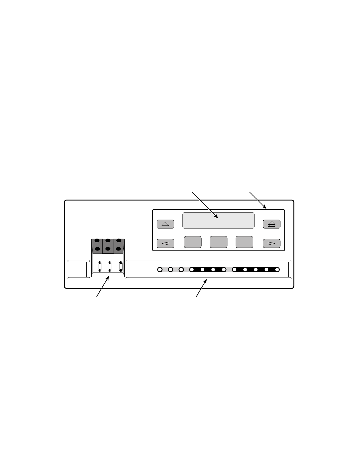
Front Panel
The E1 DSU/CSU front panel (Figure 1-1) contains,
• One 2-line, 16-alphanumeric-character-per-line
liquid crystal display (LCD)
• One 7-button keypad (three Function and four
directional keys)
• Twelve light-emitting diodes (LEDs)
Six test jacks
•
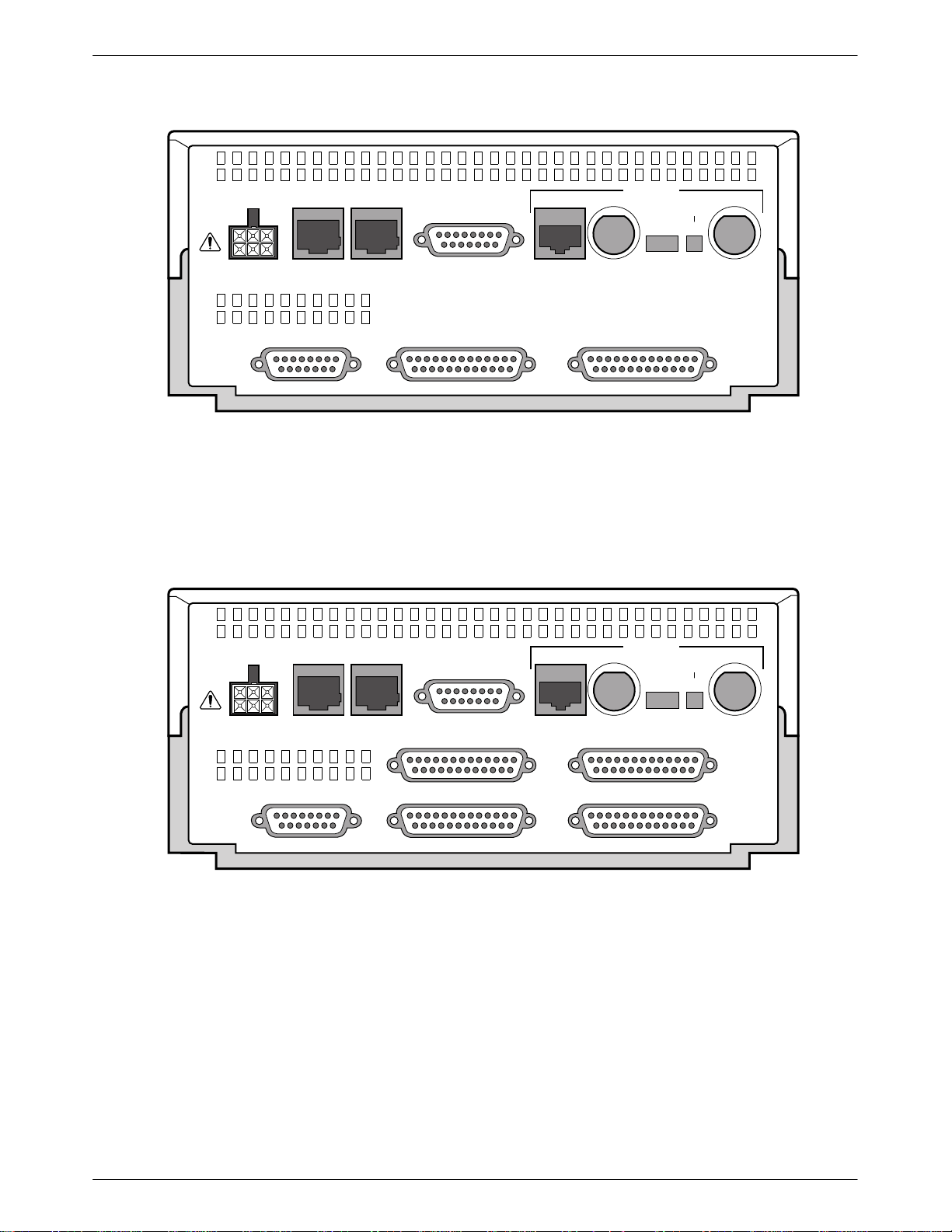
Rear Panel
The E1 DSU/CSU rear panel contains the connectors
and switches required for the operation of the E1
DSU/CSU (Figures 1-2 and 1-3). The connectors and
switches are described in T
LCD
able 1-1.
KEYPAD
ACCULINK
F1 F2 F3
NET
MON
EQPT
MON
OK
FAIL TEST SIG OOF ALRM
NET
In
OutInOutInOut
TEST JACKS LEDs
Figure 1-1. Front Panel
EER SIG ALRM PDVOOF BPV
NETWORK RXD
DTR TXD CTS RTS
496-14539-0
1-33170-A2-GB20-20 December 1996
ACCULINK 317x E1 DSU/CSU
2
2
POWER
CAUTION: AUX PORT OR COM PORT MUST NOT BE
CONNECTED TO PSTN OR E1 NETWORK
AUX
PORT
COM
PORT
Figure 1-2. Model 3172 Rear Panel
DTE
120Ω
NETWORK
TX
75Ω
RX SHIELD
120Ω
75Ω
OPEN
EARTH
RX
75Ω
PORT 1 PORT 2CLOCK IN
495-14295-0
POWER
CAUTION: AUX PORT OR COM PORT MUST NOT BE
CONNECTED TO PSTN OR E1 NETWORK
AUX
PORT
COM
PORT
Figure 1-3. Model 3174 Rear Panel
NETWORK
TX
DTE
120Ω
75Ω
PORT 3 PORT 4
PORT 1 PORT 2CLOCK IN
120Ω
75Ω
RX SHIELD
OPEN
EARTH
RX
75Ω
495-14294-0
1-4 December 1996 3170-A2-GB20-20

Table 1-1
Rear Panel Connectors and Switches
Introduction
Name
POWER Supplies power to the E1 DSU/CSU by providing an attachment for the ac power
module or the optional dc power cable (+24 or –48 Vdc).
AUX PORT Supports SNMP LAN Adapter or daisy-chain connections.
COM PORT Provides access to a locally connected PC, an ASCII terminal or printer, or an
SNMP management link.
DTE Provides access to the DTE Drop/Insert interface. This interface is compatible
with the signal format of CCITT Recommendation G.703 and the frame structure
of CCITT Recommendation G.704.
NETWORK—120Ω
NETWORK—75Ω TX/RX
NETWORK—120Ω/75Ω (switch)
NETWORK—RX SHIELD (switch) Selects either an “open” or “earth” shield connection for the 75 ohm RX interface.
CLOCK IN Used to attach an external clock to the E1 DSU/CSU.
PORTs 1– 4 Used to connect the customer’s synchronous data DTE to the E1 DSU/CSU.
Provides an unkeyed modular jack for a 120 ohm balanced network interface.
Provides two BNC connectors (Transmit and Receive) for a 75 ohm unbalanced
network interface.
Selects either a 120 ohm balanced network interface or a 75 ohm unbalanced
network interface.
(This switch must be set to “open” when using the 120 ohm interface.)
Function
1-53170-A2-GB20-20 December 1996
Installation
2
Overview 2-1. . . . . . . . . . . . . . . . . . . . . . . . . . . . . . . . . . . . . . . . . . . . . . . . . . . . . . . . . . . . . . . . . . . . . . . . . .
Application Examples 2-1. . . . . . . . . . . . . . . . . . . . . . . . . . . . . . . . . . . . . . . . . . . . . . . . . . . . . . . . . . . . . . . .
SNMP Connection Examples 2-3. . . . . . . . . . . . . . . . . . . . . . . . . . . . . . . . . . . . . . . . . . . . . . . . . . . . . . . . . .
Important Instructions 2-5. . . . . . . . . . . . . . . . . . . . . . . . . . . . . . . . . . . . . . . . . . . . . . . . . . . . . . . . . . . . . . . .
Optional Power Sources 2-5. . . . . . . . . . . . . . . . . . . . . . . . . . . . . . . . . . . . . . . . . . . . . . . . . . . . . . . . . . . . . .
Installing the +24 Vdc Power Supply 2-5. . . . . . . . . . . . . . . . . . . . . . . . . . . . . . . . . . . . . . . . . . . . . . . . .
Installing the Single –48 Vdc Power Supply 2-6. . . . . . . . . . . . . . . . . . . . . . . . . . . . . . . . . . . . . . . . . . . .
Installing the Redundant –48 Vdc Power Supply 2-7. . . . . . . . . . . . . . . . . . . . . . . . . . . . . . . . . . . . . . . .
Cabling Examples 2-8. . . . . . . . . . . . . . . . . . . . . . . . . . . . . . . . . . . . . . . . . . . . . . . . . . . . . . . . . . . . . . . . . . .
Power-Up Self-Test 2-9. . . . . . . . . . . . . . . . . . . . . . . . . . . . . . . . . . . . . . . . . . . . . . . . . . . . . . . . . . . . . . . . . .
2
Overview
This chapter contains information for installing your
E1 DSU/CSU. It includes application examples, cabling,
and power-up information.
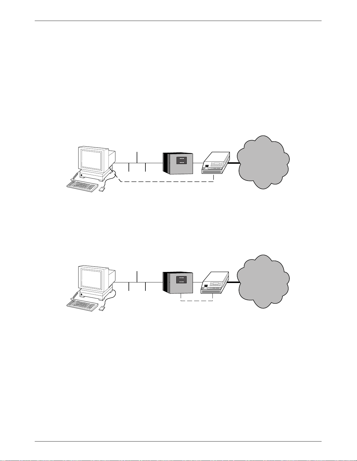
Application Examples
The E1 DSU/CSU is designed to provide an interface
between the E1 digital network and the customer premises
equipment. The E1 DSU/CSU is connected to the
customer premises equipment through one of the
synchronous data ports (PORTs 1–
LAN
ROUTER
4) or the DTE
NETWORK
DSU/CSU
Drop/Insert port (DTE). It is connected to the network
through the Network interface (NETWORK). The most
common applications for the E1 DSU/CSU are:
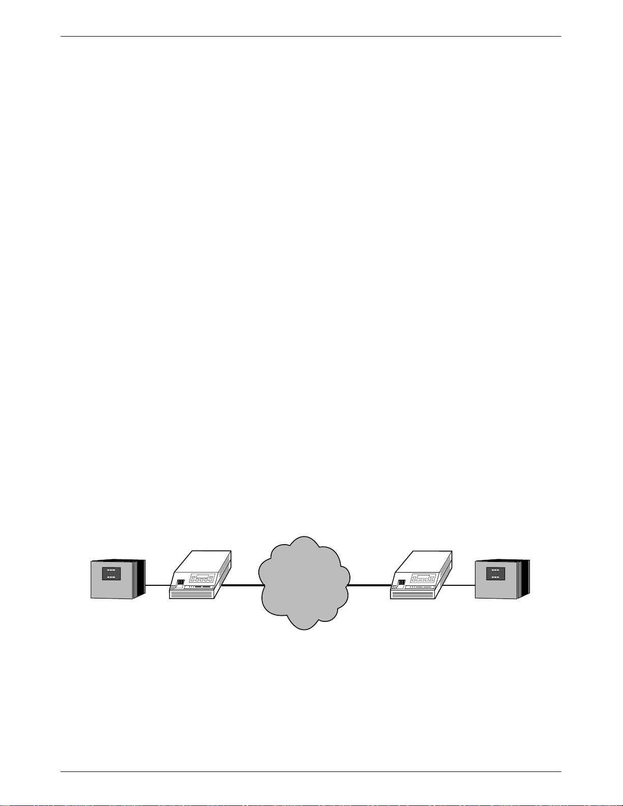
• Point-to-Point LAN interconnection (Figure 2-1).
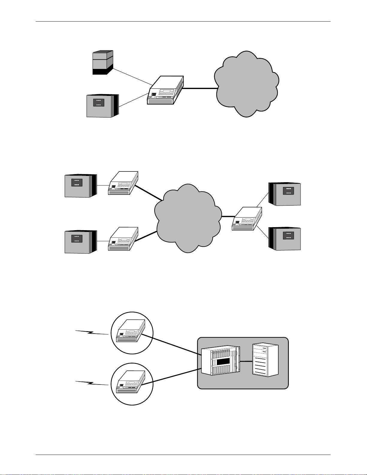
Shared access to network-based services
•
(Figure 2-2).
• Fractional E1 network applications (Figure 2-3).
ireless/DACS (Digital Access and Cross-connect
• W
System) applications (Figure 2-4).
Both voice and data applications are supported.
DSU/CSU
LAN
ROUTER
Figure 2-1. Point-to-Point Application Example
496-14296a-0
2-13170-A2-GB20-20 December 1996
ACCULINK 317x E1 DSU/CSU
3
3
1
LAN
ROUTER
PBX
LAN
ROUTER
NETWORK
SERVICES
DSU/CSU
Figure 2-2. Shared Access Application Example
DSU/CSU
FRACTIONAL
NETWORK
DSU/CSU
496-14312-0
LAN
ROUTER
LAN
ROUTER
WIRELESS
WIRELESS
DSU/CSU
Figure 2-3. Fractional E1 Application Example
DSU/CSU
CELL SITE
DACS
DSU/CSU
CELL SITE
MOBILE SWITCHING
LAN
ROUTER
496-14313-0
MOBILE SWITCH
CENTER
496-14700-0
Figure 2-4. Wireless/DACS Application Example
2-2 December 1996 3170-A2-GB20-20
Installation
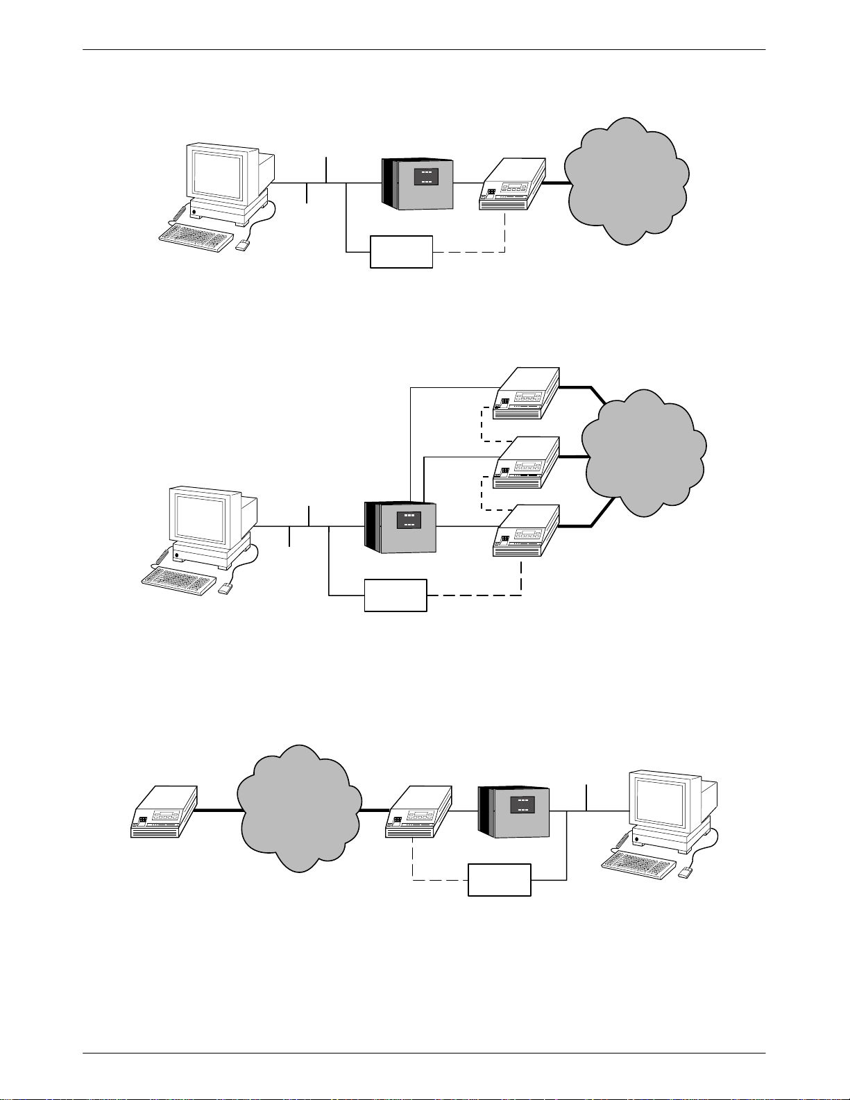
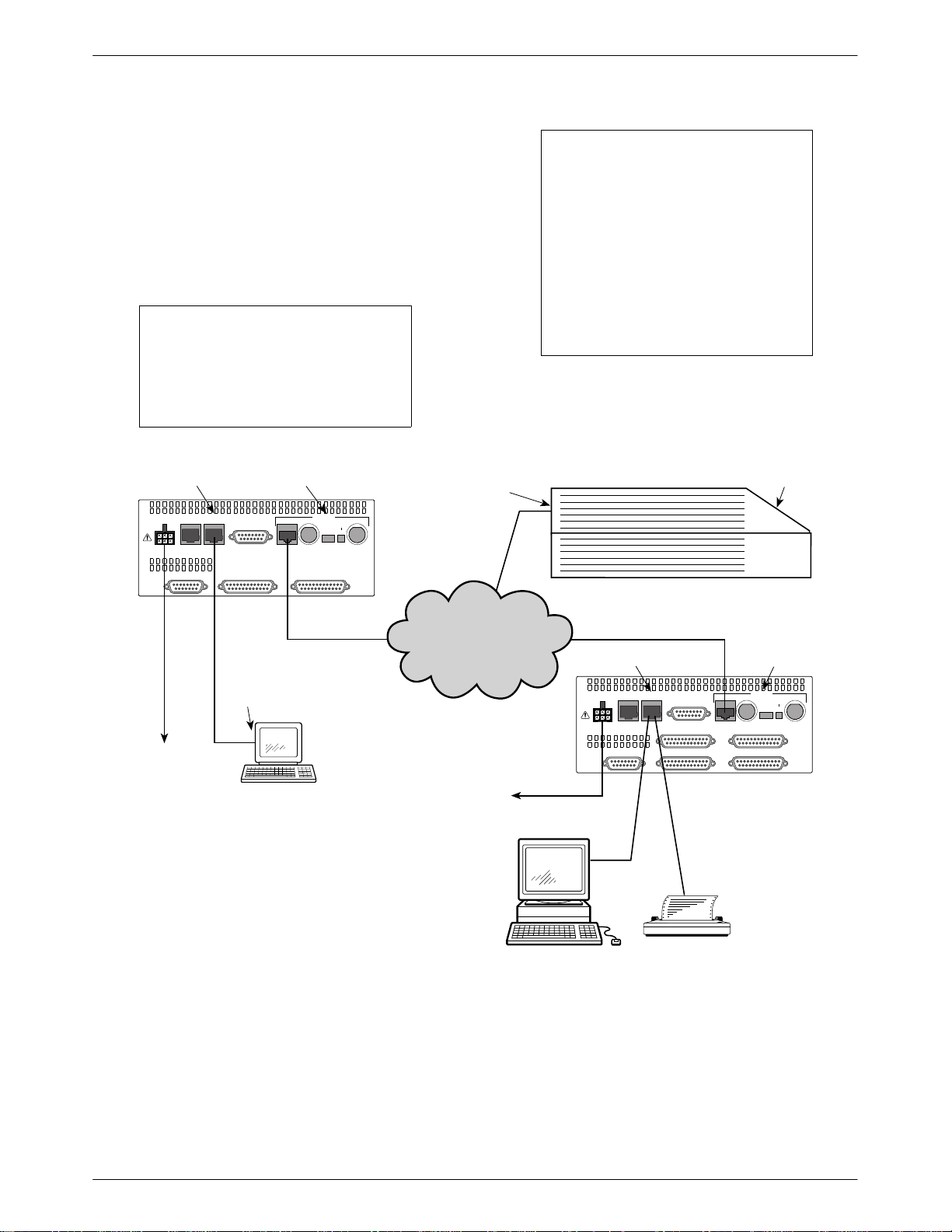
SNMP Connection Examples
The
E1 DSU/CSU can be connected to an SNMP
management system in a number of ways. Some examples
include:
• Directly connecting the COM port to the SNMP
manager (Figure 2-5).
• Connecting the COM port to a network device (e.g.,
a router) for SNMP management (Figure 2-6).
SNMP
ETHERNET
SNMP
PPP/SLIP
Figure 2-5. Direct Connection to an SNMP Manager
LAN
ROUTER
• Connecting the COM port or the AUX port to an
external LAN Adapter for Ethernet SNMP
connectivity (Figure 2-7).
Daisy chaining the COM port of one device to the
•
AUX port of the other to provide SNMP
connectivity (Figure 2-8).
• Remotely managing the E1 DSU/CSU through the
Facility Data Link (FDL) or the synchronous data
port’s Embedded Data Link (EDL) (Figure 2-9).
DSU/CSU
NETWORK
496-14672a
SNMP
ETHERNET
LAN
ROUTER
DSU/CSU
SNMP
PPP/SLIP
Figure 2-6. Connection through a Router to SNMP
NETWORK
496-14420b
2-33170-A2-GB20-20 December 1996
ACCULINK 317x E1 DSU/CSU
SNMP
NMS
ETHERNET
LAN
ROUTER
LAN
ADAPTER
DSU/CSU
SNMP
PPP
Figure 2-7. Connection through a LAN Adapter to SNMP
DSU/CSU
SNMP
NMS
ETHERNET
LAN
ROUTER
SNMP
PPP
SNMP
PPP
DSU/CSU
DSU/CSU
NETWORK
496-14548a
NETWORK
DSU/CSU
SNMP
LAN
ADAPTER
PPP
Figure 2-8. LAN Adapter and Daisy Chaining for SNMP Support
DSU/CSU
LAN
ROUTER
ETHERNET
NETWORK
SNMP
FDL/EDL
SNMP
PPP
LAN
ADAPTER
Figure 2-9. Remote SNMP Management through FDL/EDL
496-14549a
496-14550a
2-4 December 1996 3170-A2-GB20-20
Installation
Important Instructions
Read and follow all warning notices and instructions
marked on the E1 DSU/CSU or included in this guide.
CAUTION
Disconnect the power cable
before connecting or removing
any data cables at the rear of
the unit.
HANDLING PRECAUTIONS
FOR
STA
TIC-SENSITIVE DEVICES
This product is designed to protect
sensitive components from damage
due to electrostatic discharge (ESD)
during normal operation. When
performing installation procedures,
however, take proper static control
precautions to prevent damage to
equipment. If you are not sure of the
proper static control precautions,
contact your near
representative.
est sales or service
Optional Power Sources
The E1 DSU/CSU is typically powered by the ac
power module. Use the following procedures only if
you want to use an optional dc power source.
Using the optional dc power cable, the E1 DSU/CSU is
capable of operating on either a +24 Vdc power source,
48 Vdc single source battery
–
source batteries (for power backup). T
choose one of the following power supply types.
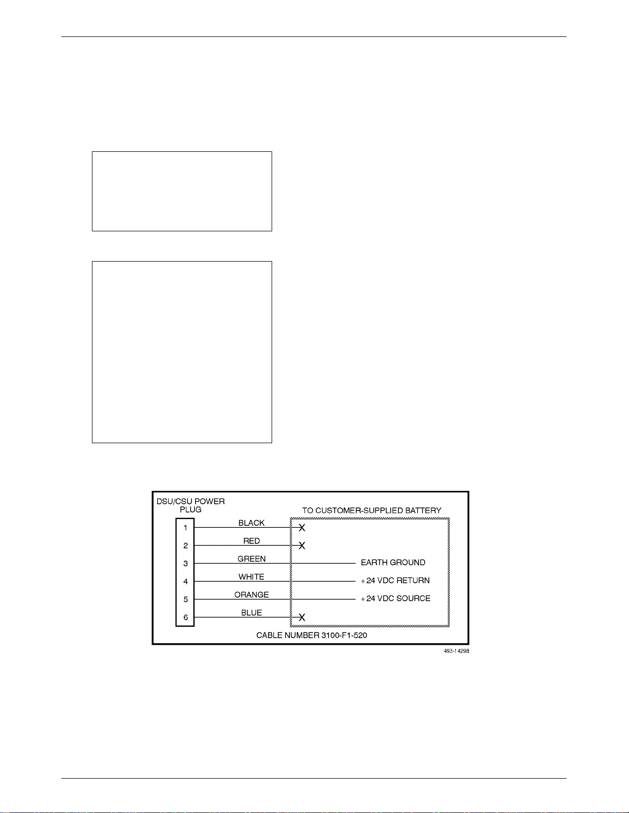
Installing the +24 Vdc Power Supply
To
install the E1 DSU/CSU using a +24
supply, refer to Figure 2-10 and use the following
procedure.
o install the +24 Vdc power supply
T
1. Connect the green wire to a suitable earth ground.
2. Connect the white wire to the +24 Vdc return.
3.
Connect the orange wire to the +24 Vdc source.
4. Cut the black, red and blue wires off at the outer
insulation.
5. Plug the power connector into the E1 DSU/CSU.
, or –48 Vdc redundant
o select the power
Vdc power
,
,
Figure 2-10. +24 Vdc Power Supply Pinouts
2-53170-A2-GB20-20 December 1996
ACCULINK 317x E1 DSU/CSU
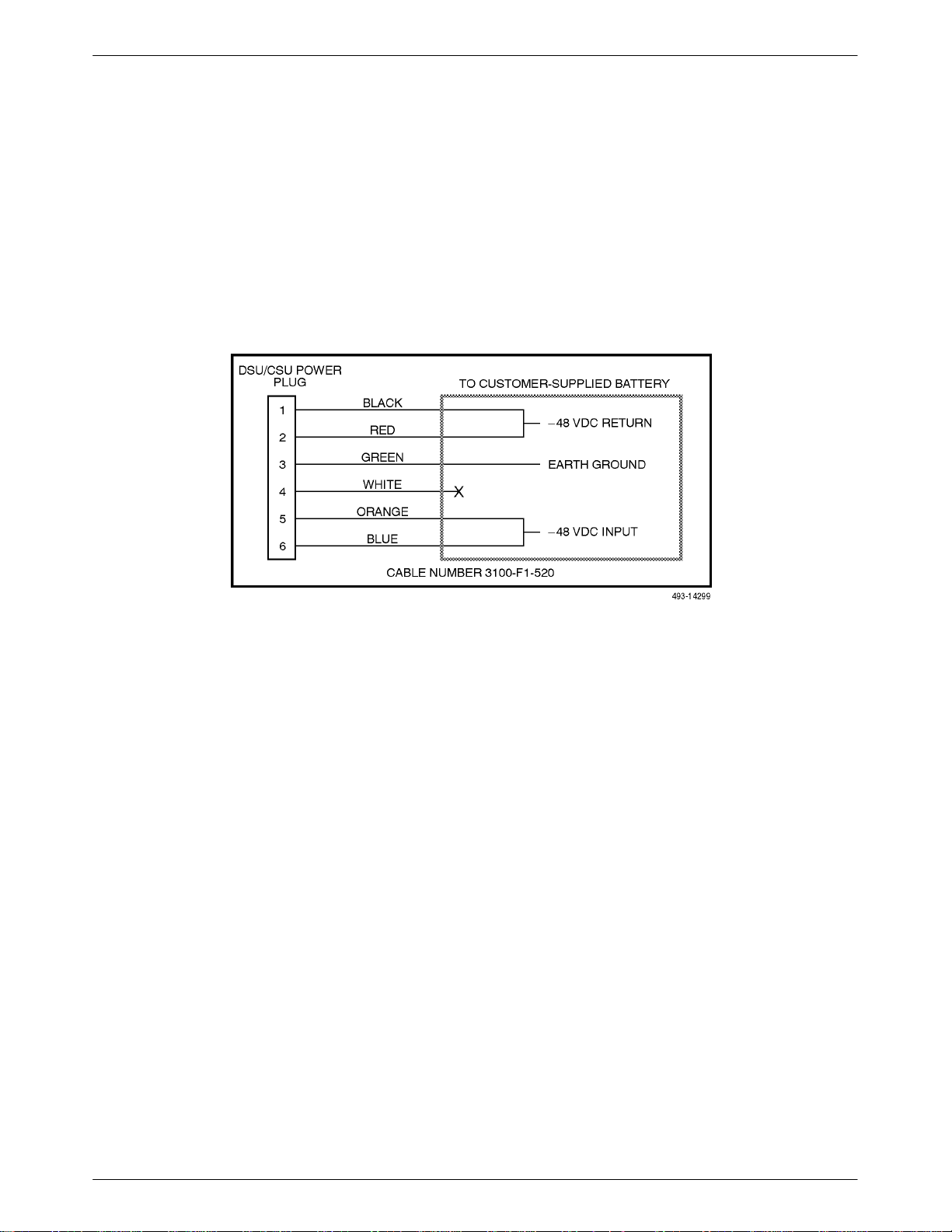
Installing the Single –ā48 Vdc Power Supply
To
install the E1 DSU/CSU using a single source
–48
Vdc power supply
following procedure.
o install the –
T
1.
Connect the black and red wires to the –48 Vdc
return source.
, refer to Figure 2-1
1 and use the
48 Vdc single source power supply
,
2. Connect the green wire to a suitable earth ground.
3.
Connect the orange and blue wires to the –48 Vdc
input source.
4. Cut the white wire off at the outer insulation.
5. Plug the power connector into the E1 DSU/CSU.
Figure 2-11. –ā48 Vdc Single Source Power Supply Pinouts
2-6 December 1996 3170-A2-GB20-20
Installation
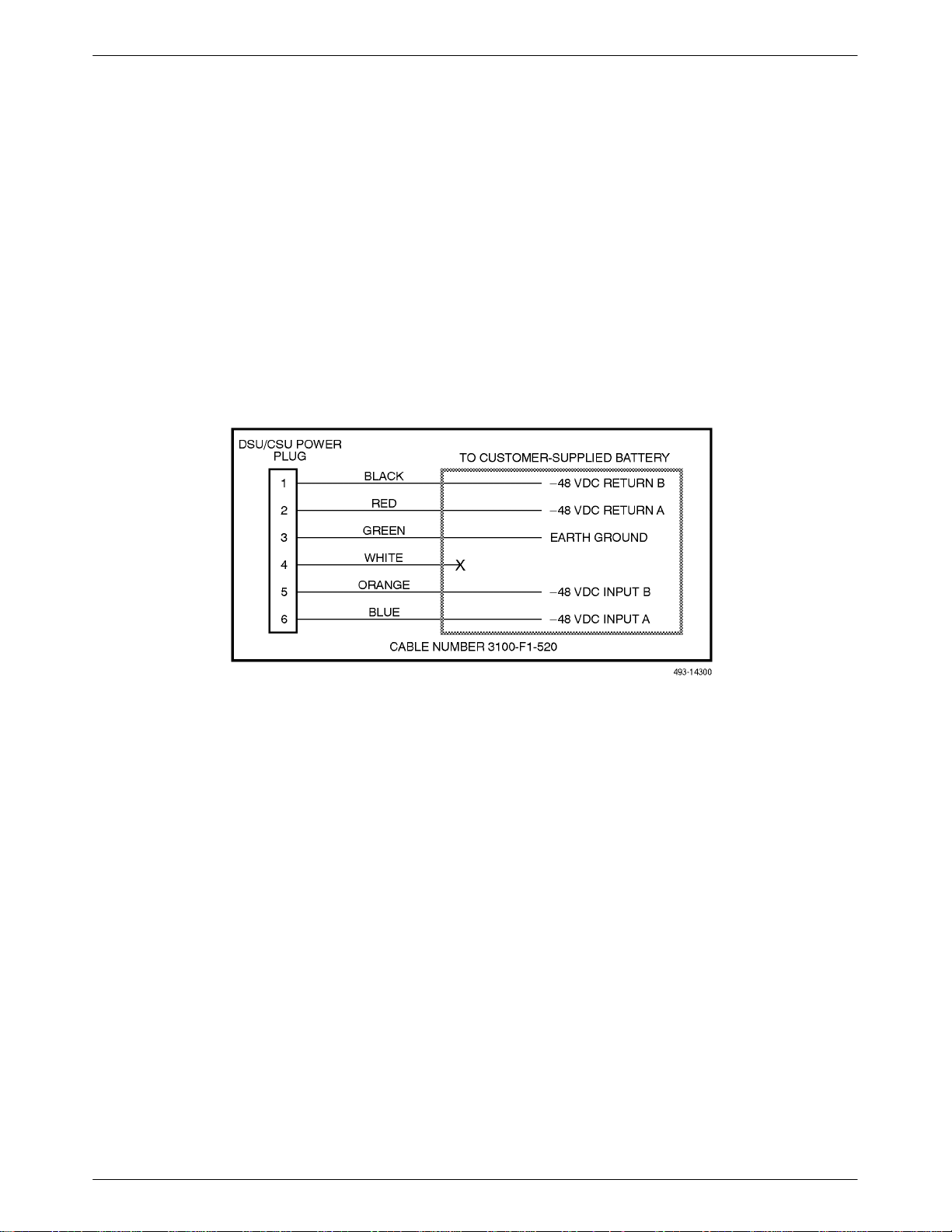
Installing the Redundant –ā48 Vdc Power
Supply
To install the E1 DSU/CSU using a redundant –
power supply, refer to Figure 2-12 and use the following
procedure.
To install the redundant –48 Vdc power supply,
1. Connect the black wire to the –48 Vdc return
source B.
2. Connect the red wire to the –48 Vdc return
source
A.
48 Vdc
3. Connect the green wire to a suitable earth ground.
4. Connect the orange wire to the –48 Vdc input
source B.
5. Connect the blue wire to the –48 Vdc input
source A.
6. Cut the white wire off at the outer insulation.
7. Plug the power connector into the E1 DSU/CSU.
Figure 2-12. –ā 48 Vdc Redundant Source Power Supply Pinouts
2-73170-A2-GB20-20 December 1996
ACCULINK 317x E1 DSU/CSU
1
Cabling Examples
The E1 DSU/CSU is supplied with an ac power
module. You must provide the DTE and network cables.
Optional cables that you can order from the company
are described in Appendix D,
Pin Assignments
Figure 2-13 illustrates some cabling examples.
CAUTION
Disconnect the power cable
before connecting or removing
any data cables at the rear of
the unit.
COM PORT
AUX
POWER
CAUTION: AUX PORT OR COM PORT MUST NOT BE
CONNECTED TO PSTN OR E1 NETWORK
COM
PORT
PORT
DTE
PORT 1 PORT 2CLOCK IN
NETWORK
NETWORK
TX
120Ω
75Ω
RX SHIELD
120Ω
OPEN
EARTH
75Ω
RX
75Ω
.
DSU/CSU
NETWORK
NOTE
The 120Ω/75Ω switch selects
either the 120 ohm balanced
network interface or the 75 ohm
unbalanced network interface.
The RX SHIELD switch selects
either an “open” or “earth” shield
connection for the 75 ohm RX
interface. (This switch must be set
to “open” when using the 120 ohm
interface.)
DSU/CSU
FRONT
PANEL
TO AC
POWER
MODULE
SERIAL
PORT
3100-F1-550
NOTE:
3100 SERIES
FRONT PANEL
EMULATION
SOFTWARE,
3100-C1-010
NETWORK
DSU/CSU
TO DC
POWER
(OPTIONAL)
3100-F1-520
SNMP
MANAGER
Figure 2-13. Cabling Examples
COM PORT
AUX
POWER
CAUTION: AUX PORT OR COM PORT MUST NOT BE
CONNECTED TO PSTN OR E1 NETWORK
COM
PORT
PORT
OR
NETWORK
DTE
120Ω
PORT 3 PORT 4
PORT 1 PORT 2CLOCK IN
3100-F1-540
75Ω
TX
NETWORK
RX
RX SHIELD
120Ω
OPEN
EARTH
75Ω
75Ω
495-14673-0
2-8 December 1996 3170-A2-GB20-20
Installation
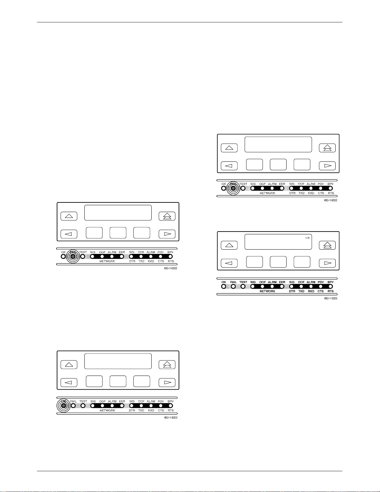
Power-Up Self-Test
After you connect the E1 DSU/CSU to a power source,
the unit performs the power-up self-test to ensure that it is
in good working order. The E1 DSU/CSU performs this
test on itself upon power-up or after a device reset unless
it has been disabled by the Self-Test configuration option
(see Appendix C,
The self-test includes a basic processor test, a limited
memory test, a code checksum test, and basic verification
tests of the internal components. The front panel LCD
displays the progress and pass/fail status of these
power
-up tests.
The power
1. Once the E1 DSU/CSU is plugged in, the In
Progress screen appears and the Fail LED blinks
ON and Off continuously.
Configuration Options
).
-up self-test consists of the following steps:
Self-Test:
P
rogress
In
F1
F2
F3
If the self-test fails, the Failed screen appears for
five seconds. The Fail LED lights, and an
eight-digit failure code (nnnnnnnn
) is displayed
for use by service personnel to determine the
cause of the self-test failure. The E1 DSU/CSU
continues to try to operate. If you are in doubt
about the results of the self-test, use the Self-Test
Health command to display the status of this test
(see the
Self-T
est Health
section in Chapter 4,
Maintenance).
Self-Test:
F1
nnnnnnnn
F2
U E
1 CEPT
F3
Failed
4. The
top-level menu screen appears.
DS
Stat Test Cnfig
2. All the LEDs then start to flash simultaneously in
the pattern twice ON, then Off. Then, the LCD
begins to flash characters and numbers in the same
pattern, alternating with the flashing LEDs.
3.
If the self-test is successful, the Passed screen
appears for one second, the Fail LED turns Off
and the OK LED lights.
Self-Test:
Passed
F1
F2
F3
F1
F2
F3
2-93170-A2-GB20-20 December 1996

Operation
Overview 3-2. . . . . . . . . . . . . . . . . . . . . . . . . . . . . . . . . . . . . . . . . . . . . . . . . . . . . . . . . . . . . . . . . . . . . . . . . .
Using the Front Panel 3-2. . . . . . . . . . . . . . . . . . . . . . . . . . . . . . . . . . . . . . . . . . . . . . . . . . . . . . . . . . . . . . . .
LCD 3-3. . . . . . . . . . . . . . . . . . . . . . . . . . . . . . . . . . . . . . . . . . . . . . . . . . . . . . . . . . . . . . . . . . . . . . . . . . .
Keypad 3-3. . . . . . . . . . . . . . . . . . . . . . . . . . . . . . . . . . . . . . . . . . . . . . . . . . . . . . . . . . . . . . . . . . . . . . . . .
Test Jacks 3-4. . . . . . . . . . . . . . . . . . . . . . . . . . . . . . . . . . . . . . . . . . . . . . . . . . . . . . . . . . . . . . . . . . . . . . .
LEDs 3-4. . . . . . . . . . . . . . . . . . . . . . . . . . . . . . . . . . . . . . . . . . . . . . . . . . . . . . . . . . . . . . . . . . . . . . . . . .
Displaying Unit Identity 3-8. . . . . . . . . . . . . . . . . . . . . . . . . . . . . . . . . . . . . . . . . . . . . . . . . . . . . . . . . . . . . .
Displaying LED Conditions 3-10. . . . . . . . . . . . . . . . . . . . . . . . . . . . . . . . . . . . . . . . . . . . . . . . . . . . . . . . . . .
Selecting the DTE Drop/Insert or Data Port for LED Display 3-11. . . . . . . . . . . . . . . . . . . . . . . . . . . . . . . . .
Changing Configuration Options 3-11. . . . . . . . . . . . . . . . . . . . . . . . . . . . . . . . . . . . . . . . . . . . . . . . . . . . . . .
Displaying/Editing Configuration Options 3-12. . . . . . . . . . . . . . . . . . . . . . . . . . . . . . . . . . . . . . . . . . . . .
Saving Edit Changes 3-13. . . . . . . . . . . . . . . . . . . . . . . . . . . . . . . . . . . . . . . . . . . . . . . . . . . . . . . . . . . . . .
Selecting/Copying to a Specific Port 3-13. . . . . . . . . . . . . . . . . . . . . . . . . . . . . . . . . . . . . . . . . . . . . . . . . .
Configuring the E1 DSU/CSU for SNMP Management 3-14. . . . . . . . . . . . . . . . . . . . . . . . . . . . . . . . . . . . . .
Selecting the Port 3-14. . . . . . . . . . . . . . . . . . . . . . . . . . . . . . . . . . . . . . . . . . . . . . . . . . . . . . . . . . . . . . . . .
Setting the IP Address 3-15. . . . . . . . . . . . . . . . . . . . . . . . . . . . . . . . . . . . . . . . . . . . . . . . . . . . . . . . . . . . .
Selecting the Link Layer Protocol 3-16. . . . . . . . . . . . . . . . . . . . . . . . . . . . . . . . . . . . . . . . . . . . . . . . . . . .
Specifying the Community Name(s) and Access Type(s) 3-17. . . . . . . . . . . . . . . . . . . . . . . . . . . . . . . . . .
Configuring SNMP Traps 3-18. . . . . . . . . . . . . . . . . . . . . . . . . . . . . . . . . . . . . . . . . . . . . . . . . . . . . . . . . . . . .
Enabling SNMP Trap Messages 3-18. . . . . . . . . . . . . . . . . . . . . . . . . . . . . . . . . . . . . . . . . . . . . . . . . . . . .
Selecting the Number of Trap Managers 3-19. . . . . . . . . . . . . . . . . . . . . . . . . . . . . . . . . . . . . . . . . . . . . . .
Configuring a Destination for SNMP Traps 3-19. . . . . . . . . . . . . . . . . . . . . . . . . . . . . . . . . . . . . . . . . . . .
Configuring DS0 Channels 3-20. . . . . . . . . . . . . . . . . . . . . . . . . . . . . . . . . . . . . . . . . . . . . . . . . . . . . . . . . . . .
Displaying DS0 Channel Assignments 3-27. . . . . . . . . . . . . . . . . . . . . . . . . . . . . . . . . . . . . . . . . . . . . . . .
Allocating Data Ports 3-28. . . . . . . . . . . . . . . . . . . . . . . . . . . . . . . . . . . . . . . . . . . . . . . . . . . . . . . . . . . . . .
Block Channel Assignment Method 3-29. . . . . . . . . . . . . . . . . . . . . . . . . . . . . . . . . . . . . . . . . . . . . . . . . .
Individual Channel Assignment Method 3-30. . . . . . . . . . . . . . . . . . . . . . . . . . . . . . . . . . . . . . . . . . . . . . .
Allocating DS0 Channels from the Drop/Insert Interface to the Network Interface 3-30. . . . . . . . . . . . . .
Clearing DS0 Channel Allocation 3-32. . . . . . . . . . . . . . . . . . . . . . . . . . . . . . . . . . . . . . . . . . . . . . . . . . . .
Providing Backup Capability 3-32. . . . . . . . . . . . . . . . . . . . . . . . . . . . . . . . . . . . . . . . . . . . . . . . . . . . . . . . . .
Selecting the Timing Source 3-33. . . . . . . . . . . . . . . . . . . . . . . . . . . . . . . . . . . . . . . . . . . . . . . . . . . . . . . . . . .
Configuring for Network Timing 3-34. . . . . . . . . . . . . . . . . . . . . . . . . . . . . . . . . . . . . . . . . . . . . . . . . . . .
Configuring for External Timing 3-34. . . . . . . . . . . . . . . . . . . . . . . . . . . . . . . . . . . . . . . . . . . . . . . . . . . . .
Acquiring/Releasing the User Interface 3-35. . . . . . . . . . . . . . . . . . . . . . . . . . . . . . . . . . . . . . . . . . . . . . . . . .
Acquiring the Active User Interface 3-35. . . . . . . . . . . . . . . . . . . . . . . . . . . . . . . . . . . . . . . . . . . . . . . . . .
Releasing the Active User Interface 3-35. . . . . . . . . . . . . . . . . . . . . . . . . . . . . . . . . . . . . . . . . . . . . . . . . .
Resetting the E1 DSU/CSU 3-36. . . . . . . . . . . . . . . . . . . . . . . . . . . . . . . . . . . . . . . . . . . . . . . . . . . . . . . . . . .
Download Operations 3-36. . . . . . . . . . . . . . . . . . . . . . . . . . . . . . . . . . . . . . . . . . . . . . . . . . . . . . . . . . . . . . . .
3
3-13170-A2-GB20-20 December 1996
ACCULINK 317x E1 DSU/CSU
3
Overview
This chapter contains information for operating your
E1 DSU/CSU. It includes a description of the front panel
and sample procedures for configuring the E1 DSU/CSU.
ACCULINK
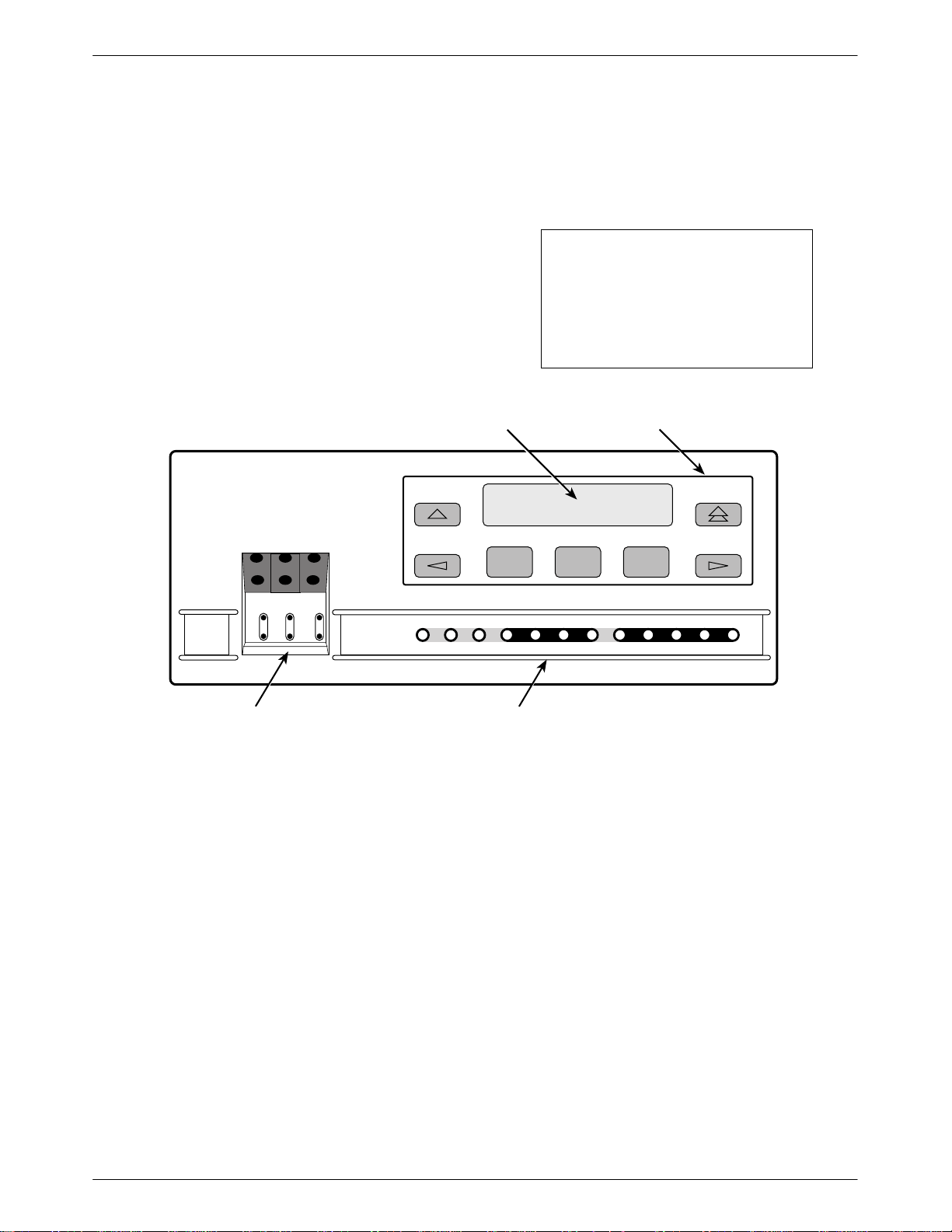
Using the Front Panel
The E1 DSU/CSU front panel (Figure 3-1) consists of
an LCD, a keypad, test jacks, and 12 LEDs.
NOTE
You can display a graphical
representation of the E1
DSU/CSU front panel on an
attached PC (see Appendix G,
Front Panel Emulation
LCD
F1 F2 F3
KEYPAD
).
NET
MON
EQPT
MON
OK
FAIL TEST SIG OOF ALRM
NET
In
OutInOutInOut
TEST JACKS LEDs
Figure 3-1. E1 DSU/CSU Front Panel
EER SIG ALRM PDVOOF BPV
NETWORK RXD
DTR TXD CTS RTS
496-14539-0
3-2 December 1996 3170-A2-GB20-20
Operation
LCD
The LCD (Figure 3-2) displays two types of data:
Messages such as alarms, command/test
•
completion, and action in progress
• Front panel menu tree information (see
A,
Appendix
The LCD displays status messages as requested via the
Device Health and Status branch of the front panel menu
(see the
Device Health and Status section in Chapter 4,
Maintenance). In addition, the highest level status
message appears on the front panel automatically if no
front panel action has occurred at the E1 DSU/CSU for
the past five minutes.
The LCD also lists commands, configuration options,
and test results. In most cases, the top line shows the
command or option name and default value, while the
second line displays options and responses. When a
response is required, select from the options displayed
directly above the Function keys (F1, F2, F3); make your
choice by pressing the corresponding Function key.
Front Panel Menu)
F1 F2
Figure 3-2. LCD
F3
Keypad
The 7-button keypad (Figure 3-3) enables you to
navigate through the menu tree and select choices
presented on the second line of the LCD.
F1 F2
Figure 3-3. Keypad
Use the
Use the
key to move up the menu.
F1 F2
key to exit any part of the menu in which
you may be operating. You immediately return to the
top-level menu screen shown on the front panel menu (see
Appendix A, Front Panel Menu).
F3
F3
F1 F2
F3
Use the Function (F1, F2, F3) keys to make selections
from the choices presented on the second line of the LCD.
When this line presents choices, it is generally divided
into three sections, each displayed directly above one of
the Function keys. When your choice appears above one
of the Function keys, press that key to select that choice.
F1 F2
F3
3-33170-A2-GB20-20 December 1996
ACCULINK 317x E1 DSU/CSU
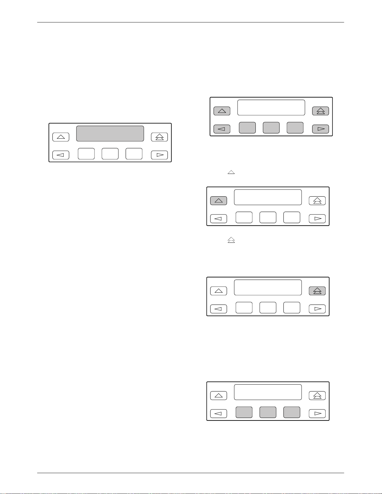
The scroll keys (
and
) serve one of two functions,
depending on whether a menu screen or a data entry
screen appears on the front panel.
For data entry screens, the
character to the left while the
key scrolls one
key scrolls one
character to the right.
For menu screens, the key scrolls to the previous
menu choice while the
key scrolls to the next menu
choice.
If a choice is available to the left of the screen, the
character ← appears on the top line. If a choice is
available to the right of the screen, the → character
appears on the top line. If choices are available to both the
right and the left of the screen, two arrows appear (
).
The arrows indicate that you must use the scroll keys to
bring the additional options onto the screen.
F1 F2
F3
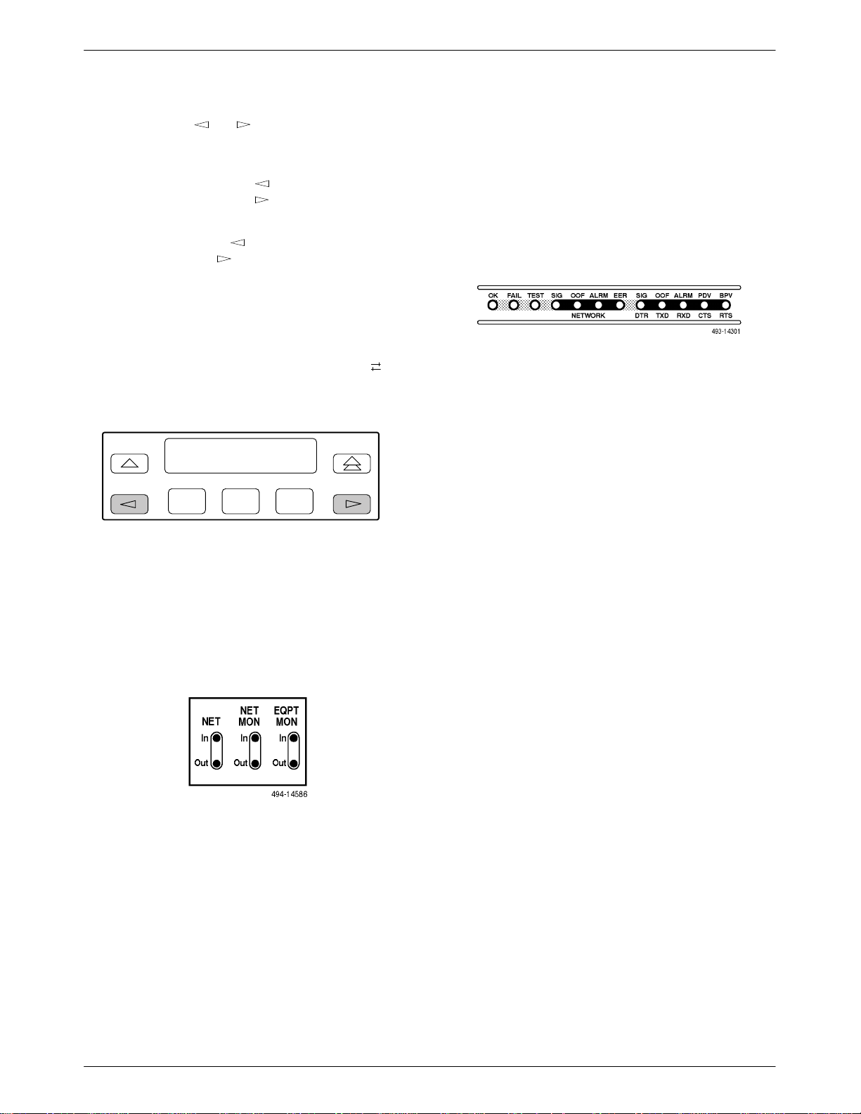
LEDs
There are twelve LEDs on the E1 DSU/CSU front
panel. The five LEDs on the right (Figure 3-5) are shared
between the DTE Drop/Insert port and the data ports.
Refer to the Selecting the DTE Dr
for LED Display
which port’
section later in this chapter to choose
s status the LEDs display
Figure 3-5. E1
A green LED indicates normal operation. A yellow
LED indicates a warning (for the DTE Drop/Insert port)
or activity (for the data ports). Conditions are sampled
every tenth of a second.
The twelve front panel LEDs are grouped into four
sections to indicate the status of the:
op/Insert or Data Port
.
DSU/CSU LEDs
Test Jacks
Six test jacks are located on the front panel
(Figure 3-4). These are described in the T
in Chapter 4, Maintenance.
Figure 3-4. Test Jacks
est Jacks
section
• System (Table 3-1)
• NETWORK interface (Table 3-2)
• DTE Drop/Insert Port (Table 3-3)
• Data Ports (Table 3-4)
3-4 December 1996 3170-A2-GB20-20

Table 3-1
System LEDs
Operation
Name
OK Green Indicates the current operational state of the E1 DSU/CSU.
FAIL Yellow Indicates a system failure or a self-test.
TEST Yellow A system test is in progress.
Color Meaning
ON:
OFF:
BLINKING:
ON:
OFF:
BLINKING
ON:
OFF:
The E1 DSU/CSU is operational and has power.
The E1 DSU/CSU is performing a power-up self-test or a system
failure has occurred.
A software download is in progress.
A device error/fault is detected or a reset has just occurred.
No system failures are detected.
: A self-test is in progress.
A loopback or pattern test has been initiated either locally, by the
network, or externally.
No tests are active.
Table 3-2
NETWORK Interface LEDs
Name
SIG Green Monitors the signal being received from the network.
OOF Yellow Monitors Out Of Frame (OOF) conditions on the received network signal.
ALRM Yellow Indicates whether an alarm condition exists on the received network signal.
EER Yellow Indicates when the excessive error rate has been exceeded on the network
Color Meaning
ON:
OFF:
ON
OFF:
ON:
OFF:
interface.
ON:
OFF:
: At least one OOF was detected on the signal during the sampling
A recoverable signal is being received from the network.
The signal cannot be recovered from the network (a Loss of Signal
condition exists).
period.
No OOFs were detected on the signal during the sampling period.
An alarm condition (LOS, LOF, EER, RAI, AIS) exists on the
received network signal. Use the Device Health and Status
command to determine the alarm type.
No alarm condition exists on the network interface signal.
The excessive error rate has been exceeded on the network
interface.
The excessive error rate has not been exceeded on the network
interface.
3-53170-A2-GB20-20 December 1996

ACCULINK 317x E1 DSU/CSU
Table 3-3
DTE Drop/Insert Port LEDs
Name
SIG Green Monitors the signal being received from the DTE Drop/Insert port.
OOF Yellow Monitors Out Of Frame (OOF) conditions on the received DTE Drop/Insert signal.
ALRM Yellow Indicates whether an alarm condition exists on the received DTE Drop/Insert signal.
PDV Yellow Monitors Pulse Density Violations (PDV) on the received DTE Drop/Insert signal.
Color Meaning
ON:
OFF:
ON:
OFF:
ON:
OFF:
ON
: At least one PDV was detected (and corrected) on the received
OFF:
A recoverable signal is being received from the DTE Drop/Insert
port.
The signal cannot be recovered from the DTE Drop/Insert port
(a Loss of Signal condition exists).
At least one OOF was detected on the signal during the sampling
period.
No OOFs were detected on the signal during the sampling period.
An alarm condition (LOS, LOF, EER, RAI, AIS) exists on the
received DTE Drop/Insert signal. Use the Device Health and Status
command to determine the alarm type.
No alarm condition exists on the DTE Drop/Insert Interface signal.
DTE Drop/Insert signal during the sampling period.
No PDVs were detected on the received DTE Drop/Insert signal
during the sampling period.
BPV Yellow Monitors Bipolar Violations (BPV) on the received DTE Drop/Insert signal.
ON:
OFF:
At least one BPV was detected (and corrected) on the received
DTE Drop/Insert signal during the sampling period.
No BPVs were detected on the received DTE Drop/Insert signal
during the sampling period.
3-6 December 1996 3170-A2-GB20-20

Table 3-4
Data Port LEDs
Operation
Name
DTR Green Monitors the state of interchange circuit CD (CCITT 108/1, /2) – Data Terminal Ready
TXD Yellow Monitors activity on interchange circuit BA (CCITT 103) – Transmitted Data. This is the
RXD Yellow Monitors activity on interchange circuit BB (CCITT 104) – Received Data. This is data
CTS Yellow Monitors the state of interchange circuit CB (CCITT 106) – Clear-to-Send sent to the
Color Meaning
received from the synchronous data DTE.
ON:
OFF:
data sent from the synchronous data DTE to the data port on the E1 DSU/CSU.
ON:
OFF:
CYCLING:
sent to the synchronous data DTE from the data port on the E1 DSU/CSU.
ON:
OFF:
CYCLING:
synchronous data DTE.
ON:
OFF:
DTR is being asserted by the synchronous data DTE.
DTR is not being asserted.
Ones are being received from the synchronous data DTE.
Zeros are being received from the synchronous data DTE.
Both ones and zeros are being received from the synchronous
data DTE.
Ones are being sent to the synchronous data DTE.
Zeros are being sent to the synchronous data DTE.
Both ones and zeros are being sent to the synchronous data DTE.
CTS is being asserted by the E1 DSU/CSU.
CTS is not being asserted.
RTS Yellow Monitors the state of interchange circuit CA (CCITT 105) – Request-to-Send received
from the synchronous data DTE.
ON:
OFF:
RTS is being asserted by the synchronous data DTE.
RTS is not being asserted.
3-73170-A2-GB20-20 December 1996
ACCULINK 317x E1 DSU/CSU
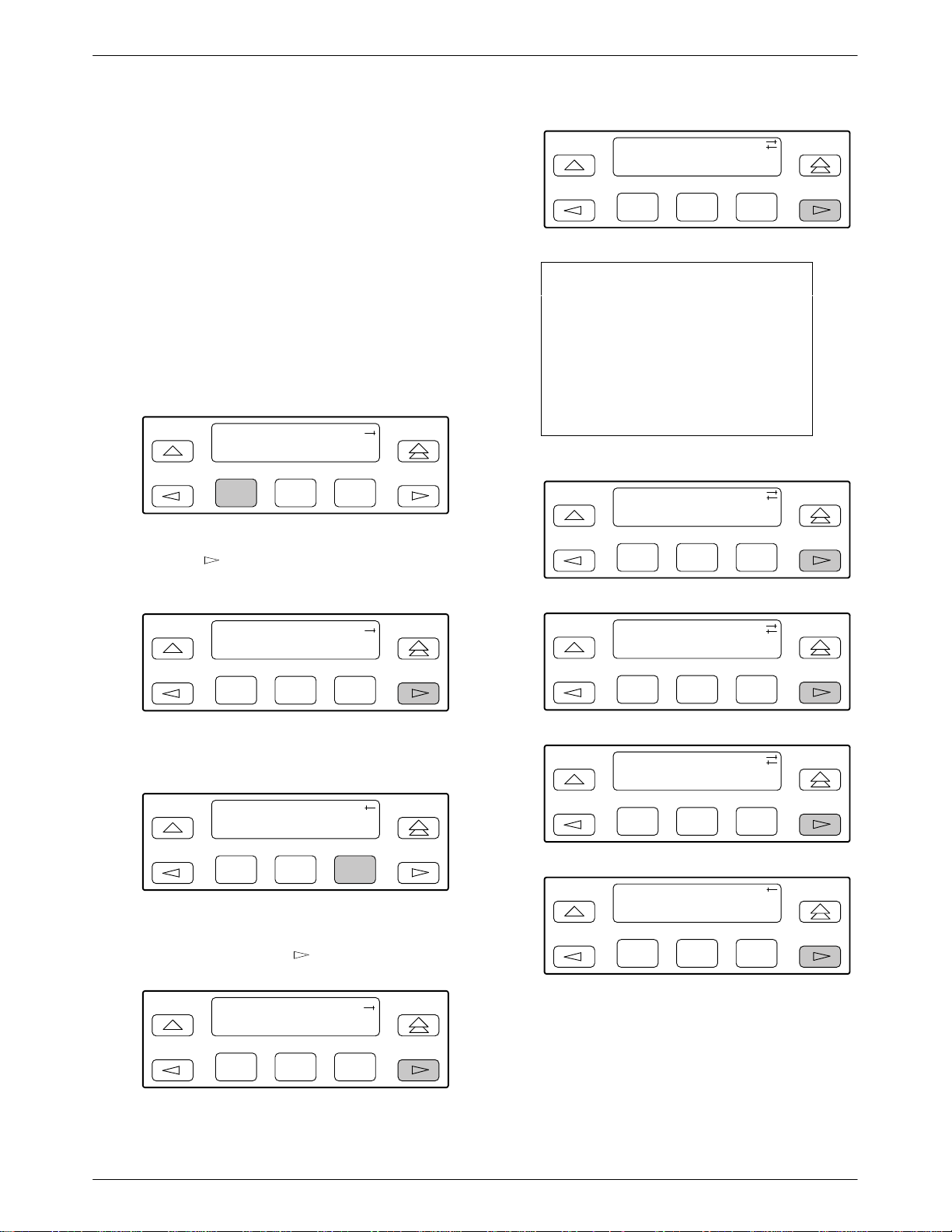
Displaying Unit Identity
The identity of the E1 DSU/CSU (serial number, model
number, software revision level, hardware revision level,
and customer identification) is available through the
Status branch of the front panel menu (see Appendix A,
Front Panel Menu).
The customer identification is the only identity number
you can change.
To display the E1 DSU/CSU’s identity (ID),
1. Press F1 to select Status from the top-level menu
screen.
DS
Stat Test Cnfig
2. Press the
to bring the ID selection onto the front panel LCD.
U E
1 CEPT
F1
F2
F3
key three times on the Status screen
Identity:
Mod=xxxx-xx-xxx
F1
F2
F3
NOTE
The third-from-last digit in the
model number may vary due to
the type of power supply shipped
with the E1 DSU/CSU. Refer to
the label on the bottom of the E1
DSU/CSU for the correct model
number.
Identity:
Cust ID=xxxxxxxx
F1
F2
F3
Status:
DevHS STest Perf
F1
F2
F3
3. Press F3 to select ID from the Status screen.
Status:
TStat LED ID
F1
F2
F3
4. The following screens appear in the order listed
each time you press the
key
.
Identity:
Ser=xxxxxxx
F1
F2
F3
Identity:
SRev=xx.xx.xx
F1
F2
Identity:
CCA1=xxxx-xxx
F1
F2
Identity:
CCA2=xxxx-xxx
F1
F2
F3
F3
F3
3-8 December 1996 3170-A2-GB20-20
 Loading...