

Paradyne 3170 Quick Reference

ACCULINK 3170 E1
DSU/CSU
QUICK REFERENCE
Document No. 3170-A2-GL10-00

Copyright 1999 Paradyne Corporation.
All rights reserved.
Printed in U.S.A.
Notice
This publication is protected by federal copyright law. No part of this publication may be
copied or distributed, transmitted, transcribed, stored in a retrieval system, or translated
into any human or computer language in any form or by any means, electronic,
mechanical, magnetic, manual or otherwise, or disclosed to third parties without the
express written permission of Paradyne Corporation, 8545 126th Ave. N., Largo,
FL 33773.
Paradyne Corporation makes no representation or warranties with respect to the
contents hereof and specifically disclaims any implied warranties of merchantability or
fitness for a particular purpose. Further, Paradyne Corporation reserves the right to
revise this publication and to make changes from time to time in the contents hereof
without obligation of Paradyne Corporation to notify any person of such revision or
changes.
Changes and enhancements to the product and to the information herein will be
documented and issued as a new release to this manual.
Warranty, Sales, and Service Information
Contact your local sales representative, service representative, or distributor directly for
any help needed. For additional information concerning warranty, sales, service, repair,
installation, documentation, training, distributor locations, or Paradyne worldwide office
locations, use one of the following methods:
Via the Internet: Visit the Paradyne World Wide Web site at
http://www.paradyne.com
Via Telephone: Call our automated call system to receive current information via
fax or to speak with a company representative.
— Within the U.S.A., call 1-800-870-2221
— Outside the U.S.A, call 1-727-530-2340
Document Feedback
We welcome your comments and suggestions about this document. Please mail them
to Technical Publications, Paradyne Corporation, 8545 126th Ave. N., Largo, FL 33773,
or send e-mail to userdoc@eng.paradyne.com. Include the number and title of this
document in your correspondence. Please include your name and phone number if you
are willing to provide additional clarification.
Trademarks
All products and services mentioned herein are the trademarks, service marks,
registered trademarks or registered service marks of their respective owners.

TM
1
ACCULINK 3170 E1 DSU/CSU
Quick Reference
Document Number 3170-A2-GL10-00
January 1999
Product Documentation on the World Wide Web
We provide complete product documentation online. This lets you search the
documentation for specific topics and print only what you need, reducing the waste of
surplus printing. It also helps us maintain competitive prices for our products.
Complete documentation for this product is available at www.paradyne.com.
Select
Service & Support → Technical Manuals → T1/E1 Digital Access Devices.
Select the following document:
3170-A2-GB20
ACCULINK 317x E1 Data Service Unit/Channel Service Unit Operator’s Guide
To request a paper copy of a Paradyne document:
Within the U.S.A., call 1-800-PARADYNE (1-800-727-2396)
Outside the U.S.A., call 1-727-530-8623
Before installing the DSU/CSU, read the
Important Safety Instructions
beginning on
page 14.

2
Quick Start Procedure
The following procedure is for experienced DSU/CSU users who are familiar with the
317x DSU/CSU installation process and have no special requirements for their
application. See the
ACCULINK 317x E1 Data Service Unit/Channel Service Unit
Operator’s Guide
for more information.
1. 317x DSU/CSUs are shipped with a power cable appropriate to the country of
installation. Attach the power module cord to the rear of the DSU/CSU and the
other end to a grounded ac power outlet. If you intend instead to use a 24 or
–48 vdc power supply, see the Operator’s Guide.
2. Attach the 317x DSU/CSU network connection to the E1 network using the
appropriate cable. Attach the 317x DSU/CSU to the customer premises equipment
via the DTE and port connectors.
3. If you intend to use front panel emulation, connect the cable from the PC to the
COM port on the rear panel of the DSU/CSU.
4. Power on the DSU/CSU to perform the power-up self-test.
5. During the power-up self-test, the FAIL LED flashes, then all LEDs blink twice.
When the test is complete, verify that the DSU/CSU is functional by observing that
the OK, NETWORK SIG, and DTE SIG LEDs are lit.
6. If you intend to manage the 317x DSU/CSU with SNMP, cable either the COM or
AUX port (as appropriate for your configuration). Then, configure the SNMP
management link.
7. If you do not intend to use the DTE Drop/Insert E1 port, disable it using the
configuration procedures in Chapter 3,
Operation
, and Appendix C,
Configuration
Options
, of the Operator’s Guide. (The default setting for this port is Enabled.)
8. Configure the ports and channels you intend to use and assign channels to the
network interface.
3
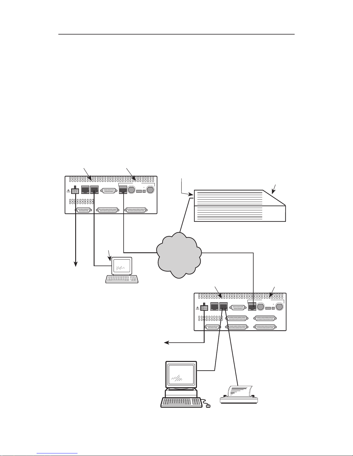
Cabling Examples
The E1 DSU/CSU is supplied with an ac power module. You must provide the DTE and
network cables.
Optional cables that you can order from the company are described in Appendix D,
Pin
Assignments
.
NOTE:
The 120Ω/75Ω switch selects either the 120-ohm balanced network interface or
the 75-ohm unbalanced network interface. The RX SHIELD switch selects either an
“open” or “earth” shield connection for the 75-ohm RX interface. (This switch must
be set to “open” when using the 120-ohm interface.)
POWER
AUX
PORT
COM
PORT
DTE
PORT 3 PORT 4
PORT 1 PORT 2CLOCK IN
120ý
75ý
75ý
120ý
RX SHIELD
OPEN
EARTH
RX
75ý
TX
NETWORK
CAUTION: AUX PORT OR COM PORT MUST NOT BE
CONNECTED TO PSTN OR E1 NETWORK
POWER
AUX
PORT
COM
PORT
DTE
PORT 1 PORT 2CLOCK IN
120ý
75ý
75ý
120ý
RX SHIELD
OPEN
EARTH
RX
75ý
TX
NETWORK
CAUTION: AUX PORT OR COM PORT MUST NOT BE
CONNECTED TO PSTN OR E1 NETWORK
98-14673a
NETWORK
TO AC
POWER
MODULE
TO DC
POWER
(OPTIONAL)
3100-F1-550
3100-F1-540
FRONT
PANEL
DSU/CSU
DSU/CSU
DSU/CSU
SERIAL
PORT
COM PORT
NETWORK
COM PORT
NETWORK
3100 SERIES
FRONT PANEL
EMULATION
SOFTWARE,
3100-C1-010
NOTE:
3100-F1-520
NETWORK
SNMP
MANAGER
OR
4
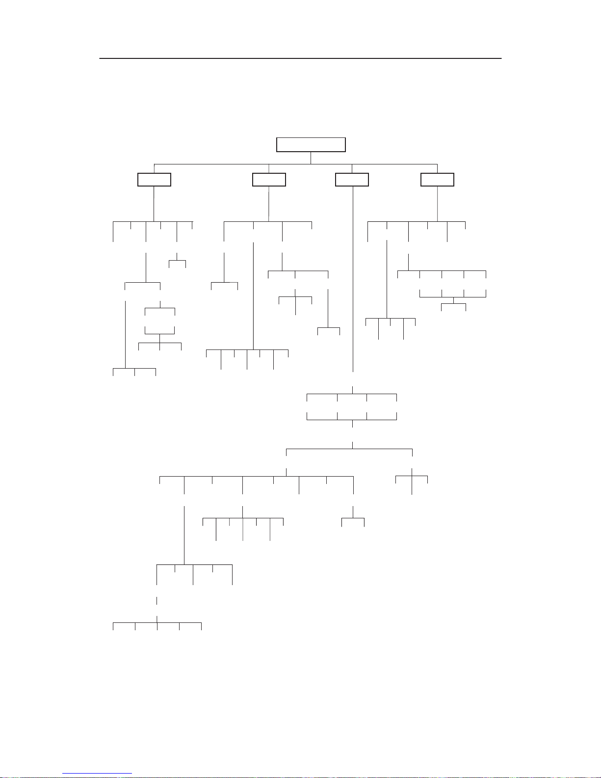
Configuration Options
Configuration options are accessed from the Cnfig branch of the front panel menu.
DSU E1 CEPT
Stat
Test
98-14606a
DevHs
STest
Perf
TStat
LED
ID
E1 Prtn
Rlpbk
Lpbk
Ptrns
Lamp
Cnfig
Ctrl
Rel ClrReg
Reset
CID
LED
DL
DTE
Prt1
Prt2
Prt3
Prt4
PLB
DLB
RLB
LLB
Abort
DCLB
DTLB
Abort
Send
Mon
QRSS
1in8
511
QRSS 511
NET Prt1 Prt2 Prt3 Prt4
FarNear
PrtnNET
FarNear
Cur 8Tot Intvl
Cur 24Tot Intvl
DCLBUPDCLB
DN
Edit
Save
Load Edit Area From:
Choose Function:
Cust1
Activ Cust2
Activ Cust1 Cust2 Fact
User
Alarm
NETDTE
Port Chan
Gen
SNMP
Gen Trap
DTE
Prt1
Prt2
Prt3
Prt4
Clear
Dsply
Copy
Prt1
Prt2
Prt3
Prt4
Port Select :
All Prt1 Prt2 Prt3 Prt4
 Loading...