

Page 1

ACCULINK
316x DATA SERVICE UNIT/
CHANNEL SERVICE UNIT
(INCLUDES TERMINAL USER
INTERFACE)
OPERATOR’S GUIDE
Document No. 3160-A2-GB22-10
December 1996
Page 2

ACCULINK 316x DSU/CSU
ACCULINK
316x Data Service Unit/Channel Service Unit
(includes Terminal User Interface)
Operator’s Guide
3160-A2-GB22-10
2nd
Edition (December 1996)
Changes
and enhancements to the product and to the information herein will be documented and issued as a new release to
this manual.
Standalone
FCC Registration number:
See label on unit
Ringer Equivalence number (REN): See label on unit
Canadian Certification number: See label on unit
Canadian DOC Load number: See label on unit
Carrier Card
FCC Registration number:
See label on unit
Ringer Equivalence number (REN): See label on unit
Canadian Certification number: See label on unit
Canadian DOC Load number: See label on unit
Warranty, Sales, and Service Information
Contact your sales or service representative directly for any help needed. For additional information concerning warranty,
sales, service, repair
• Via the Internet:
ia T
• V
elephone: Call our automated call system to receive current information via fax or to speak with a company
representative.
— Within the U.S.A., call 1-800-870-2221
— International, call 813-530-2340
, installation, documentation, or training, use one of the following methods:
V
isit the Paradyne World W
ide W
eb site at http://www
.paradyne.com
Trademarks
All products and services mentioned herein are the trademarks, service marks, registered trademarks or registered service
marks of their respective owners.
Printed on recycled paper
COPYRIGHT E 1996 Paradyne Corporation. All rights reserved.
This
publication is protected by federal copyright law
or
translated into any human or computer language in any form or by any means, electronic, mechanical, magnetic, manual or otherwise, or disclosed to third parties
without
the express written permission of Paradyne Corporation, 8545 126th A
Paradyne
Corporation makes no representation or warranties with respect to the contents hereof and specifically disclaims any implied warranties of
or
fitness for a particular purpose. Further
hereof
without obligation of Paradyne Corporation to notify any person of such revision or changes.
A December 1996 3160-A2-GB22-10
, Paradyne Corporation reserves the right to revise this publication and to make changes from time to time in the contents
. No part of this publication may
venue North, P
be copied or distributed, transmitted, transcribed, stored in a retrieval system,
.O. Box 2826, Largo, Florida 33779-2826.
merchantability
Page 3

Important Safety Instructions
1. Read and follow all warning notices and instructions marked on the product or
included in the manual.
2. This product is intended to be used with a three-wire grounding type plug - a plug
which has a grounding pin. This is a safety feature. Equipment grounding is vital to
ensure safe operation. Do not defeat the purpose of the grounding type plug by
modifying the plug or using an adaptor.
Prior to installation, use an outlet tester or a voltmeter to check the ac receptacle for
the presence of earth ground. If the receptacle is not properly grounded, the
installation must not continue until a qualified electrician has corrected the problem.
If a three-wire grounding type power source is not available, consult a qualified
electrician to determine another method of grounding the equipment.
3. Slots and openings in the cabinet are provided for ventilation. To ensure reliable
operation of the product and to protect it from overheating, these slots and openings
must not be blocked or covered.
4. Do not allow anything to rest on the power cord and do not locate the product where
persons will walk on the power cord.
Safety Instructions
5. Do not attempt to service this product yourself, as opening or removing covers may
expose you to dangerous high voltage points or other risks. Refer all servicing to
qualified service personnel.
6. General purpose cables are provided with this product. Special cables, which may be
required by the regulatory inspection authority for the installation site, are the
responsibility of the customer.
7. When installed in the final configuration, the product must comply with the applicable
Safety Standards and regulatory requirements of the country in which it is installed. If
necessary, consult with the appropriate regulatory agencies and inspection
authorities to ensure compliance.
8. A rare phenomenon can create a voltage potential between the earth grounds of two
or more buildings. If products installed in separate buildings are interconnected, the
voltage potential may cause a hazardous condition. Consult a qualified electrical
consultant to determine whether or not this phenomenon exists and, if necessary,
implement corrective action prior to interconnecting the products.
9. Models 3160/3164/3165 Input Power to the AC voltage configuration of this product
must be provided by a UL Listed or CSA Certified, Class 2 transformer. Input power
to the DC voltage configurations of this product must be provided by a National
Electric Code (NEC) or a Canadian Electric Code (CEC), Part 1, Class 2 circuit.
In addition, if the equipment is to be used with telecommunications circuits, take the
following precautions:
– Never install telephone wiring during a lightning storm.
– Never install telephone jacks in wet locations unless the jack is specifically designed
for wet locations.
– Never touch uninsulated telephone wires or terminals unless the telephone line has
been disconnected at the network interface.
– Use caution when installing or modifying telephone lines.
– Avoid using a telephone (other than a cordless type) during an electrical storm.
There may be a remote risk of electric shock from lightning.
– Do not use the telephone to report a gas leak in the vicinity of the leak.
B3160-A2-GB22-10 December 1996
Page 4

ACCULINK 316x DSU/CSU
Notices
C December 1996 3160-A2-GB22-10
Page 5

Government Requirements and Equipment Return
Certain governments require that instructions pertaining to DSU/CSU and modem connection to
the telephone network be included in the installation and operation manual. Specific instructions
are listed in the following sections.
United States
Government Requirements
NOTICE TO USERS OF THE UNITED STA
1. This equipment complies with Part 68 of the FCC rules. On the equipment is a label that
contains, among other information, the FCC registration number and ringer equivalence
number (REN) for this equipment. The label is located on the bottom of the 3160/3164
DSU/CSU, and on the 3161 DSU/CSU circuit card. If requested, this information must be
provided to the telephone company.
2. There are two types of telephone lines associated with the standalone equipment. The T1
network connection should be made using a Universal Service Order Code (USOC) type
RJ48C jack. The Service Order Code 6.0F should be specified to the telephone company
when ordering the T1 line. In addition, the proper Facility Interface Code must be specified
to the T
elephone Company
following framing format and line signaling techniques. The DSU/CSU configuration must
correspond to the T1 line’s parameters. The 3160/3164 DSU/CSU internal modem
connects to the Public Switched Telephone Network using a USOC T
Facility Interface Code 02LS2 along with the RJ1
telephone company when ordering a dial line for the modem. The 3161 DSU/CSU
connects to the T1 network using the multi-line USOC-type RJ48H jack and does not have
a PSTN interface.
Code
04DU9-BN 1.544 Mbps superframe format (SF) without line power
TES TELEPHONE NETWORK
. The DSU/CSU can be configured to support any of the
1C jack should be specified to the
316x DSU/CSU Facility Interface Codes
Description
ype RJ1
1C jack. The
04DU9-DN 1.544 Mbps SF and B8ZS without line power
04DU9-1KN 1.544 Mbps ANSI ESF without line power
04DU-1SN 1.544 Mbps ANSI ESF and B8ZS without line power
3. The ringer equivalence number (REN) is used to determine the quantity of devices which
may be connected to the telephone line. Excessive RENs on the telephone line may result
in the devices not ringing in response to an incoming call. In most, but not all areas, the
sum of the RENs should not exceed five (5.0). To be certain of the number of devices that
may be connected to the line, as determined by the total RENs, contact the telephone
company to determine the maximum RENs for the calling area.
4. If the 316x DSU/CSU causes harm to the telephone network, the telephone company will
notify you in advance that temporary discontinuance of service may be required. But if
advance notice is not practical, the telephone company will notify the customer as soon as
possible. Also, you will be advised of your right to file a complaint with the FCC if you
believe it is necessary
.
D3160-A2-GB22-10 December 1996
Page 6

ACCULINK 316x DSU/CSU
5. The telephone company may make changes in its facilities, equipment, operations, or
procedures that could affect the operation of the equipment. If this happens, the telephone
company will provide advance notice in order for you to make the necessary modifications
in order to maintain uninterrupted service.
6. If you experience trouble with this equipment, please contact your sales or service
representative (as appropriate) for repair or warranty information. If the product needs to
be returned to the company service center for repair, contact them directly for return
instructions using one of the following methods:
• Via the Internet:
ia T
• V
elephone: Call our automated call system to receive current information via fax or
isit the Paradyne World W
ide W
eb site at http://www
.paradyne.com
V
to speak with a company representative.
— Within the U.S.A., call 1-800-870-2221
— International, call 813-530-2340
If the trouble is causing harm to the telephone network, the telephone company may
request that you remove the equipment from the network until the problem is resolved.
Canada
NOTICE T
7. The equipment’
s modem cannot be used on public coin service provided by the telephone
company. Connection to Party Line Service is subject to state tarif
public utility commission, public service commission or corporation commission for
information).
8. FCC compliant telephone line cords with modular plugs are provided with this equipment.
This equipment is designed to be connected to the telephone network or premises wiring
using a compatible modular jack which is Part 68 compliant.
O USERS OF THE CANADIAN TELEPHONE NETWORK
The Canadian Department of Communications label identifies certified equipment. This
certification means that the equipment meets certain telecommunications network protective,
operational and safety requirements. The Department does not guarantee the equipment will
operate to the user’
s satisfaction.
Before installing this equipment, users should ensure that it is permissible to be connected to the
facilities of the local telecommunications company
acceptable method of connection. In some cases, the company’
single line individual service may be extended by means of a certified connector assembly
(telephone extension cord). The customer should be aware that compliance with the above
conditions may not prevent degradation of service in some situations.
fs. (Contact the state
. The equipment must also be installed using an
s inside wiring associated with a
Repairs to certified equipment should be made by an authorized Canadian maintenance facility
designated by the supplier
. Any repairs or alterations made by the user to this equipment, or
equipment malfunctions, may give the telecommunications company cause to request to disconnect
the equipment.
Users should ensure for their own protection that the electrical ground connection of the power
utility, telephone line and internal metallic water pipe system, if present, are connected together.
This precaution may be particularly important in rural areas.
E December 1996 3160-A2-GB22-10
Page 7

Government Requirements
CAUTION
Users should not attempt to make such connections
themselves, but should contact the appropriate electric
inspection authority, or electrician, as appropriate.
The load number is labeled on the equipment. The load number (LN) assigned to each terminal
device denotes the percentage of the total load to be connected to a telephone loop which is used
by the device to prevent overloading. The termination on a loop may consist of any combination of
devices subject only to the requirement that the total of the Load Numbers of all devices does not
exceed 100.
If your equipment is in need of repair, refer to the procedure in the
Equipment Return
section.
Government Requir
ements and
F3160-A2-GB22-10 December 1996
Page 8

Table of Contents
Preface
Objectives
Related Documents
Reference Documents
1. Introduction
Overview 1-1. . . . . . . . . . . . . . . . . . . . . . . . . . . . . . . . . . . . . . . . . . . . . . . .
Features 1-2. . . . . . . . . . . . . . . . . . . . . . . . . . . . . . . . . . . . . . . . . . . . . . . . .
ACCULINK 316x DSU/CSU Physical Description
2. Installation
Overview 2-1. . . . . . . . . . . . . . . . . . . . . . . . . . . . . . . . . . . . . . . . . . . . . . . .
Planning 2-1. . . . . . . . . . . . . . . . . . . . . . . . . . . . . . . . . . . . . . . . . . . . . . . . .
Box Contents
Important Safety Instructions 2-5. . . . . . . . . . . . . . . . . . . . . . . . . . . . . . . . .
Quick Start Procedure 2-5. . . . . . . . . . . . . . . . . . . . . . . . . . . . . . . . . . . . . .
Optional Power Selection 2-6. . . . . . . . . . . . . . . . . . . . . . . . . . . . . . . . . . .
Power-Up Self-Test 2-9. . . . . . . . . . . . . . . . . . . . . . . . . . . . . . . . . . . . . . . .
Selecting a Model 3161 DSU/CSU
DSU/CSU Identity 2-10. . . . . . . . . . . . . . . . . . . . . . . . . . . . . . . . . . . . . . . . .
Establishing Access Security on a Port
Setting/Changing a Password
3160/3164 DSU/CSU Cabling 2-14. . . . . . . . . . . . . . . . . . . . . . . . . . . . . . . .
Factory Default Configuration Options 2-16. . . . . . . . . . . . . . . . . . . . . . . . .
Installing Front Panel Emulation Software 2-16. . . . . . . . . . . . . . . . . . . . . .
Enabling/Disabling the Front Panel 2-17. . . . . . . . . . . . . . . . . . . . . . . . . . . .
and Reader Assumptions
vii. . . . . . . . . . . . . . . . . . . . . . . . . . .
vii. . . . . . . . . . . . . . . . . . . . . . . . . . . . . . . . . . . . . . . .
vii. . . . . . . . . . . . . . . . . . . . . . . . . . . . . . . . . . . . . .
1-4. . . . . . . . . . . . . . .
2-5. . . . . . . . . . . . . . . . . . . . . . . . . . . . . . . . . . . . . . . . . . . . .
2-10. . . . . . . . . . . . . . . . . . . . . . . . . . . .
2-12. . . . . . . . . . . . . . . . . . . . . . . . .
2-12. . . . . . . . . . . . . . . . . . . . . . . . . . . . . . . .
i3160-A2-GB22-10 December 1996
Page 9

ACCULINK 316x DSU/CSU
3. Operation
Operating the Front Panel 3-3. . . . . . . . . . . . . . . . . . . . . . . . . . . . . . . . . . .
Configuring the DSU/CSU 3-16. . . . . . . . . . . . . . . . . . . . . . . . . . . . . . . . . .
Configuring DS0 Channels 3-34. . . . . . . . . . . . . . . . . . . . . . . . . . . . . . . . . .
Timing 3-49. . . . . . . . . . . . . . . . . . . . . . . . . . . . . . . . . . . . . . . . . . . . . . . . . .
Selecting the Shared Communication Port 3-52. . . . . . . . . . . . . . . . . . . . . .
Checking the Status of the DSU/CSU
Controlling the DSU/CSU 3-61. . . . . . . . . . . . . . . . . . . . . . . . . . . . . . . . . . .
Starting Front Panel Emulation 3-69. . . . . . . . . . . . . . . . . . . . . . . . . . . . . . .
Using the Async T
4. Maintenance
Overview 4-1. . . . . . . . . . . . . . . . . . . . . . . . . . . . . . . . . . . . . . . . . . . . . . . .
Troubleshooting 4-1. . . . . . . . . . . . . . . . . . . . . . . . . . . . . . . . . . . . . . . . . . .
est Commands
T
Downloading Software 4-17. . . . . . . . . . . . . . . . . . . . . . . . . . . . . . . . . . . . .
Resetting the DSU/CSU
3-53. . . . . . . . . . . . . . . . . . . . . . . . . .
erminal Feature 3-70. . . . . . . . . . . . . . . . . . . . . . . . . . . . .
4-3. . . . . . . . . . . . . . . . . . . . . . . . . . . . . . . . . . . . . . . . . . .
4-17. . . . . . . . . . . . . . . . . . . . . . . . . . . . . . . . . . . . .
Appendices
Glossary
Index
A. Front Panel Menu A-1. . . . . . . . . . . . . . . . . . . . . . . . . . . . . . . . . . . . . .
echnical Specifications
B. T
C. Configuration Options C-1. . . . . . . . . . . . . . . . . . . . . . . . . . . . . . . . . .
Pin Assignments
D.
SNMP MIB Objects
E.
F. Troubleshooting Table F-1. . . . . . . . . . . . . . . . . . . . . . . . . . . . . . . . . .
G. Configuration Worksheets G-1. . . . . . . . . . . . . . . . . . . . . . . . . . . . . . .
H. Equipment List H-1. . . . . . . . . . . . . . . . . . . . . . . . . . . . . . . . . . . . . . . .
B-1. . . . . . . . . . . . . . . . . . . . . . . . . . . . . . . .
D-1. . . . . . . . . . . . . . . . . . . . . . . . . . . . . . . . . . . . . . .
E-1. . . . . . . . . . . . . . . . . . . . . . . . . . . . . . . . . . . .
ii December 1996 3160-A2-GB22-10
Page 10

Table of Contents
List of Figures
Figure Page
1-1 3160 DSU/CSU Front Panel 1-5. . . . . . . . . . . . . . . . . . . . . . . . . . . . . . . . . . . . . . . . . . .
1-2 3164 DSU/CSU Front Panel 1-5. . . . . . . . . . . . . . . . . . . . . . . . . . . . . . . . . . . . . . . . . . .
3160 DSU/CSU Rear Panel
1-3
3164 DSU/CSU Rear Panel
1-4
3161 DSU/CSU Faceplate
1-5
Auxiliary Backplane
1-6
2-1 Example Point-to-Point Configuration 2-2. . . . . . . . . . . . . . . . . . . . . . . . . . . . . . . . . . .
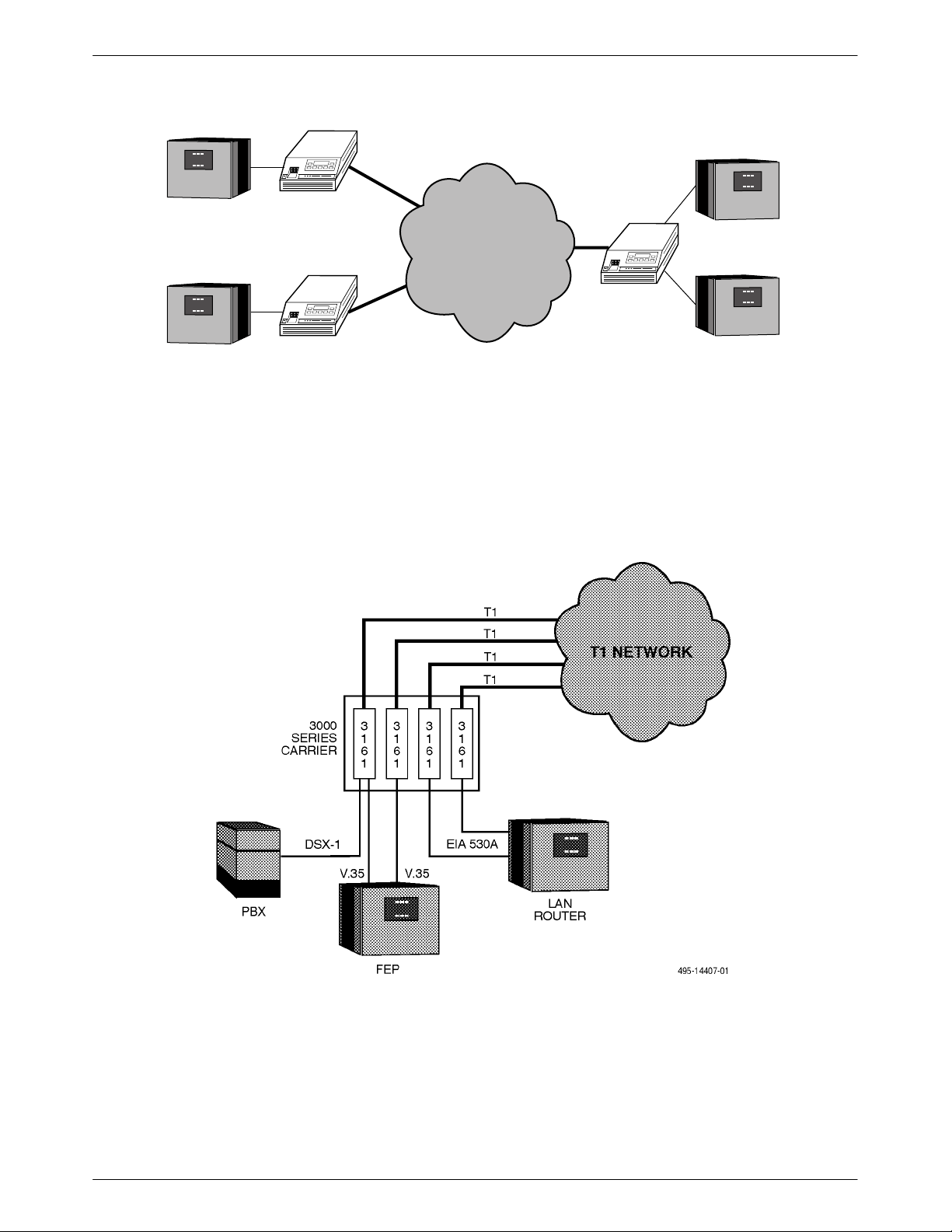
2-2 Example Shared Access to Network-Based Services Configuration 2-2. . . . . . . . . . . . .
2-3 Multiport T1 DSU/CSU in a Fractional T1 Network Configuration 2-3. . . . . . . . . . . . .
2-4 Central-Site T1 Termination Configuration 2-3. . . . . . . . . . . . . . . . . . . . . . . . . . . . . . . .
2-5 Serial Connection to SNMP 2-4. . . . . . . . . . . . . . . . . . . . . . . . . . . . . . . . . . . . . . . . . . . .
2-6 Serial Connection Through a Router to SNMP 2-4. . . . . . . . . . . . . . . . . . . . . . . . . . . . .
2-7 +24 Vdc Power Supply Pinouts 2-6. . . . . . . . . . . . . . . . . . . . . . . . . . . . . . . . . . . . . . . . .
2-8 – 48 Vdc Single Source Power Supply Pinouts 2-7. . . . . . . . . . . . . . . . . . . . . . . . . . . . .
2-9 –48 Vdc Redundant Source Power Supply Pinouts 2-8. . . . . . . . . . . . . . . . . . . . . . . . . .
Health and Status Results Screen
2-10
2-11 Setting the Password Option 2-12. . . . . . . . . . . . . . . . . . . . . . . . . . . . . . . . . . . . . . . . . . .
2-12 Password Configuration Screen 2-13. . . . . . . . . . . . . . . . . . . . . . . . . . . . . . . . . . . . . . . . .
2-13 3160/3164 DSU/CSU Cabling Configurations 2-15. . . . . . . . . . . . . . . . . . . . . . . . . . . . .
3-1 3160 DSU/CSU Front Panel 3-3. . . . . . . . . . . . . . . . . . . . . . . . . . . . . . . . . . . . . . . . . . .
Model 3161 DSU/CSU Faceplate
3-2
3-3 Shared Diagnostic Control Panel (SDCP) 3-4. . . . . . . . . . . . . . . . . . . . . . . . . . . . . . . . .
3-4 LCD 3-5. . . . . . . . . . . . . . . . . . . . . . . . . . . . . . . . . . . . . . . . . . . . . . . . . . . . . . . . . . . . . .
3-5 Keypad 3-5. . . . . . . . . . . . . . . . . . . . . . . . . . . . . . . . . . . . . . . . . . . . . . . . . . . . . . . . . . . .
3-6 LEDs 3-6. . . . . . . . . . . . . . . . . . . . . . . . . . . . . . . . . . . . . . . . . . . . . . . . . . . . . . . . . . . . .
3-7 LED Status Screen 3-12. . . . . . . . . . . . . . . . . . . . . . . . . . . . . . . . . . . . . . . . . . . . . . . . . . .
3-8 LED Display Selection Screen 3-13. . . . . . . . . . . . . . . . . . . . . . . . . . . . . . . . . . . . . . . . . .
3-9 Front Panel Emulation Screen Models 3160/3164 DSU/CSUs 3-13. . . . . . . . . . . . . . . . .
3-10 Front Panel Emulation Screen Model 3161 DSU/CSU 3-13. . . . . . . . . . . . . . . . . . . . . . .
3-11 3160/3164 DSU/CSU T
3-12 3161 DSU/CSU T
3-13 T
3-14 Configuration Branch for the Front Panel 3-17. . . . . . . . . . . . . . . . . . . . . . . . . . . . . . . . .
3-15 Configuration Branch for the Async Terminal 3-18. . . . . . . . . . . . . . . . . . . . . . . . . . . . .
3-16 Load From Screen 3-19. . . . . . . . . . . . . . . . . . . . . . . . . . . . . . . . . . . . . . . . . . . . . . . . . . .
3-17 Save To Screen 3-19. . . . . . . . . . . . . . . . . . . . . . . . . . . . . . . . . . . . . . . . . . . . . . . . . . . . . .
3-18 Save Edit Screen 3-21. . . . . . . . . . . . . . . . . . . . . . . . . . . . . . . . . . . . . . . . . . . . . . . . . . . .
3-19 Port Options Configuration Worksheets 3-22. . . . . . . . . . . . . . . . . . . . . . . . . . . . . . . . . .
3-20
est Jack Block Diagram
SNMP System Options Screen
est Jacks
est Jacks
1-6. . . . . . . . . . . . . . . . . . . . . . . . . . . . . . . . . . . . . . . . . . . .
1-6. . . . . . . . . . . . . . . . . . . . . . . . . . . . . . . . . . . . . . . . . . . .
1-8. . . . . . . . . . . . . . . . . . . . . . . . . . . . . . . . . . . . . . . . . . . . .
1-9. . . . . . . . . . . . . . . . . . . . . . . . . . . . . . . . . . . . . . . . . . . . . . . . .
2-10. . . . . . . . . . . . . . . . . . . . . . . . . . . . . . . . . . . . . . . .
3-4. . . . . . . . . . . . . . . . . . . . . . . . . . . . . . . . . . . . . . .
3-14. . . . . . . . . . . . . . . . . . . . . . . . . . . . . . . . . . . . . . . .
3-15. . . . . . . . . . . . . . . . . . . . . . . . . . . . . . . . . . . . . . . . . . . .
3-15. . . . . . . . . . . . . . . . . . . . . . . . . . . . . . . . . . . . . . . . . . . . . .
3-24. . . . . . . . . . . . . . . . . . . . . . . . . . . . . . . . . . . . . . . . .
iii3160-A2-GB22-10 December 1996
Page 11

ACCULINK 316x DSU/CSU
Figure Page
3-21 Edit User Screen 3-26. . . . . . . . . . . . . . . . . . . . . . . . . . . . . . . . . . . . . . . . . . . . . . . . . . . .
3-22 Communication Port Options Screen 3-28. . . . . . . . . . . . . . . . . . . . . . . . . . . . . . . . . . . . .
3-23 Trap Options Screen 3-33. . . . . . . . . . . . . . . . . . . . . . . . . . . . . . . . . . . . . . . . . . . . . . . . . .
3-24 Example Channel Allocation 3-35. . . . . . . . . . . . . . . . . . . . . . . . . . . . . . . . . . . . . . . . . . .
3-25 Example Interface Tables 3-36. . . . . . . . . . . . . . . . . . . . . . . . . . . . . . . . . . . . . . . . . . . . . .
3-26 DS0 Channels Containing RBS Information Worksheet 3-37. . . . . . . . . . . . . . . . . . . . . .
3-27 Example Port Channel Configuration Tables (Ports 1 and 2) Worksheet 3-38. . . . . . . . .
3-28 Example Port Channel Configuration Tables (Ports 3 and 4) Worksheet 3-39. . . . . . . . .
Display Channels Screen
3-29
3-41. . . . . . . . . . . . . . . . . . . . . . . . . . . . . . . . . . . . . . . . . . . . . .
3-30 DTE Assignment Screen 3-47. . . . . . . . . . . . . . . . . . . . . . . . . . . . . . . . . . . . . . . . . . . . . .
3-31 DTE V
oice Assignment Screen
3-47. . . . . . . . . . . . . . . . . . . . . . . . . . . . . . . . . . . . . . . . .
3-32 Common Clocking Configurations 3-49. . . . . . . . . . . . . . . . . . . . . . . . . . . . . . . . . . . . . .
3-33
3-34
Status Branch
Async T
erminal Status Branch 3-53. . . . . . . . . . . . . . . . . . . . . . . . . . . . . . . . . . . . . . . . . .
3-53. . . . . . . . . . . . . . . . . . . . . . . . . . . . . . . . . . . . . . . . . . . . . . . . . . . . . . .
3-35 Carrier (Telco) and User Register Organization 3-58. . . . . . . . . . . . . . . . . . . . . . . . . . . .
3-36 Telco Performance Report Screen 3-60. . . . . . . . . . . . . . . . . . . . . . . . . . . . . . . . . . . . . . .
3-37 User Performance Report Screen 3-60. . . . . . . . . . . . . . . . . . . . . . . . . . . . . . . . . . . . . . . .
3-38 Control Branch 3-61. . . . . . . . . . . . . . . . . . . . . . . . . . . . . . . . . . . . . . . . . . . . . . . . . . . . . .
3-39 Control Branch for the Async Terminal 3-61. . . . . . . . . . . . . . . . . . . . . . . . . . . . . . . . . . .
3-40 Call Setup Screen 3-65. . . . . . . . . . . . . . . . . . . . . . . . . . . . . . . . . . . . . . . . . . . . . . . . . . . .
Disconnect Screen
3-41
Password Access Screen
3-42
Async T
3-43
4-1 T
est Branch
erminal Top-Level Menu Screen 3-72. . . . . . . . . . . . . . . . . . . . . . . . . . . . . . . . .
3-67. . . . . . . . . . . . . . . . . . . . . . . . . . . . . . . . . . . . . . . . . . . . . . . . . . .
3-71. . . . . . . . . . . . . . . . . . . . . . . . . . . . . . . . . . . . . . . . . . . . . .
4-3. . . . . . . . . . . . . . . . . . . . . . . . . . . . . . . . . . . . . . . . . . . . . . . . . . . . . . . .
4-2 Test Branch for Async Terminal 4-3. . . . . . . . . . . . . . . . . . . . . . . . . . . . . . . . . . . . . . . .
D-1 T1 Line Interface Cable with RJ48C Connector (Feature Number 3100-F1-500) D-2. .
D-2 T1 Line Interface Cable with DA15P Connector (Feature Number 3100-F1-510) D-3. .
D-3 DSX-1 Cable D-4. . . . . . . . . . . . . . . . . . . . . . . . . . . . . . . . . . . . . . . . . . . . . . . . . . . . . . .
D-4 Integral Modem Cable (Feature Number 3150-A1-210) D-5. . . . . . . . . . . . . . . . . . . . . .
D-5 COM Port-to-PC Cable (Feature Number 3100-F1-550) D-7. . . . . . . . . . . . . . . . . . . . .
D-6 COM Port-to-Terminal/Printer Cable (Feature Number 3100-F1-540) D-8. . . . . . . . . .
D-7 EIA-530A to RS449 Adapter Cable (Feature Number 3100-F1-580) D-11. . . . . . . . . . . .
D-8 EIA-530A to V.35 Adapter Cable (Feature Number 3100-F1-570) D-13. . . . . . . . . . . . .
D-9 DC Power Cable (Feature Number 3100-F1-520) D-14. . . . . . . . . . . . . . . . . . . . . . . . . . .
D-10 External Clock Connector D-15. . . . . . . . . . . . . . . . . . . . . . . . . . . . . . . . . . . . . . . . . . . . .
D-11 Slide Latch Adapter Cable (Feature Number 3100-F1-560) D-16. . . . . . . . . . . . . . . . . . .
iv December 1996 3160-A2-GB22-10
Page 12

Table of Contents
List of Tables
Table Page
1-1 Models
1-2
3-1 System LEDs 3-7. . . . . . . . . . . . . . . . . . . . . . . . . . . . . . . . . . . . . . . . . . . . . . . . . . . . . . .
3-2 NETWORK Interface LEDs 3-8. . . . . . . . . . . . . . . . . . . . . . . . . . . . . . . . . . . . . . . . . . .
3-3 DSX-1 Drop/Insert Port LEDs 3-
3-4 Data Port LEDs 3-10. . . . . . . . . . . . . . . . . . . . . . . . . . . . . . . . . . . . . . . . . . . . . . . . . . . . .
3-5 Front Panel Emulation Screen Icons 3-14. . . . . . . . . . . . . . . . . . . . . . . . . . . . . . . . . . . . .
3-6 T
3-7 Enterprise-Specific Trap Definitions 3-31. . . . . . . . . . . . . . . . . . . . . . . . . . . . . . . . . . . . .
3-8
3-9
3-10 Self-
3-11 Performance Registers 3-57. . . . . . . . . . . . . . . . . . . . . . . . . . . . . . . . . . . . . . . . . . . . . . . .
3-12 Valid Phone Number Characters 3-68. . . . . . . . . . . . . . . . . . . . . . . . . . . . . . . . . . . . . . . .
3-13
3-14 Hard-Key Representations for Edit Screens 3-73. . . . . . . . . . . . . . . . . . . . . . . . . . . . . . .
3-15 Function Representations for Edit Screens 3-73. . . . . . . . . . . . . . . . . . . . . . . . . . . . . . . .
3-16
4-1 SNMP Trap per Interface 4-2. . . . . . . . . . . . . . . . . . . . . . . . . . . . . . . . . . . . . . . . . . . . . .
4-2 Valid Loopback Combinations 4-6. . . . . . . . . . . . . . . . . . . . . . . . . . . . . . . . . . . . . . . . . .
4-3 Valid Send T
4-4 T
B-1
B-2 ACCULINK Model 3161 DSU/CSU T
C-1 DTE Interface Configuration Options C-2. . . . . . . . . . . . . . . . . . . . . . . . . . . . . . . . . . . .
C-2 Port Configuration Options C-4. . . . . . . . . . . . . . . . . . . . . . . . . . . . . . . . . . . . . . . . . . . .
C-3 Network Interface Configuration Options C-7. . . . . . . . . . . . . . . . . . . . . . . . . . . . . . . . .
C-4 Channel Configuration Options C-9. . . . . . . . . . . . . . . . . . . . . . . . . . . . . . . . . . . . . . . . .
C-5 Data Port Channel Configuration Options C-10. . . . . . . . . . . . . . . . . . . . . . . . . . . . . . . . .
C-6 General Configuration Options C-12. . . . . . . . . . . . . . . . . . . . . . . . . . . . . . . . . . . . . . . . .
C-7 User Interface Configuration Options C-13. . . . . . . . . . . . . . . . . . . . . . . . . . . . . . . . . . . .
C-8 Alarm Configuration Options C-17. . . . . . . . . . . . . . . . . . . . . . . . . . . . . . . . . . . . . . . . . .
C-9 General SNMP Configuration Options C-20. . . . . . . . . . . . . . . . . . . . . . . . . . . . . . . . . . .
C-10 SNMP Trap Configuration Options C-22. . . . . . . . . . . . . . . . . . . . . . . . . . . . . . . . . . . . . .
3160/3614 DSU/CSUs Rear Panel Connectors
Auxiliary Backplane Connectors
est Jack Functions
Display Channel Symbols
Health and Status Messages
Test Health Messages 3-56. . . . . . . . . . . . . . . . . . . . . . . . . . . . . . . . . . . . . . . . . . .
Async T
Function Representations for Display Screens
ACCULINK Models 3160/3164 DSU/CSUs Technical Specifications
erminal Interface Configuration Options 3-70. . . . . . . . . . . . . . . . . . . . . . . . . . .
est Pattern Combinations
est Status Messages
echnical Specifications
1-7. . . . . . . . . . . . . . . . . . . . . .
1-8. . . . . . . . . . . . . . . . . . . . . . . . . . . . . . . . . . . . . . . .
3-16. . . . . . . . . . . . . . . . . . . . . . . . . . . . . . . . . . . . . . . . . . . . . . . . . .
3-40. . . . . . . . . . . . . . . . . . . . . . . . . . . . . . . . . . . . . . . . . . . . .
3-54. . . . . . . . . . . . . . . . . . . . . . . . . . . . . . . . . . . . . . . . . . . .
3-74. . . . . . . . . . . . . . . . . . . . . . . . . . . . .
4-13. . . . . . . . . . . . . . . . . . . . . . . . . . . . . . . . . . . .
4-16. . . . . . . . . . . . . . . . . . . . . . . . . . . . . . . . . . . . . . . . . . . . . . . . .
B-1. . . . . . . . . .
B-3. . . . . . . . . . . . . . . .
9. . . . . . . . . . . . . . . . . . . . . . . . . . . . . . . . . . . . . . . . . .
v3160-A2-GB22-10 December 1996
Page 13

ACCULINK 316x DSU/CSU
Table Page
D-1 T1 Network Interface Connector (J4) D-2. . . . . . . . . . . . . . . . . . . . . . . . . . . . . . . . . . . .
D-2 T1 Network Interface Connector (DA15P) D-3. . . . . . . . . . . . . . . . . . . . . . . . . . . . . . . .
D-3 (DSX-1) DTE Interface Connector (J3) D-4. . . . . . . . . . . . . . . . . . . . . . . . . . . . . . . . . . .
D-4 Integral Modem Service Port Connector (J5) D-5. . . . . . . . . . . . . . . . . . . . . . . . . . . . . .
D-5 Extended Management Port Connector (J7) D-6. . . . . . . . . . . . . . . . . . . . . . . . . . . . . . .
D-6 COM Port Connector (J6) D-8. . . . . . . . . . . . . . . . . . . . . . . . . . . . . . . . . . . . . . . . . . . . .
D-7 EIA-530A Port Interface Connector D-9. . . . . . . . . . . . . . . . . . . . . . . . . . . . . . . . . . . . .
D-8 RS449 Port Interface Connector D-10. . . . . . . . . . . . . . . . . . . . . . . . . . . . . . . . . . . . . . . .
D-9 V.35 Port Interface Connectors D-12. . . . . . . . . . . . . . . . . . . . . . . . . . . . . . . . . . . . . . . . .
D-10 DC Power Connector D-14. . . . . . . . . . . . . . . . . . . . . . . . . . . . . . . . . . . . . . . . . . . . . . . . .
D-11 External Clock Connector D-15. . . . . . . . . . . . . . . . . . . . . . . . . . . . . . . . . . . . . . . . . . . . .
D-12 Slide Latch Connector D-16. . . . . . . . . . . . . . . . . . . . . . . . . . . . . . . . . . . . . . . . . . . . . . . .
F-1 Troubleshooting F-1. . . . . . . . . . . . . . . . . . . . . . . . . . . . . . . . . . . . . . . . . . . . . . . . . . . . .
vi December 1996 3160-A2-GB22-10
Page 14

Preface
Objectives and Reader
Assumptions
This operator’
operation information for the ACCULINKr
Service Unit (DSU)/Channel Service Unit (CSU).
s guide contains installation and
316x Data
Related Documents
Contact your sales representative for additional
product documentation.
3000-A2-GA31 COMSPHERE 3000 Series
Carrier Installation Manual
3000-A2-GB41 COMSPHERE –48 VDC
Central Office Power Unit
Installation Guide
3100-A2-GK40
3160-A2-GL12
3161-A2-GL11
ACCULINK 3151 CSU and
3161 DSU/CSU General
Information Guide
ACCULINK 3160/3164
DSU/CSU Refer
ACCULINK 3161 DSU/CSU
Refer
ence Car
ence Car
d
Reference Documents
• AT&T T
• AT&T T
• ANSI T1.403-1989
• DOC Certification Standard CS-03
• CSA-22.2 No. 950-M89
CSA 108-M1983
•
• FCC Part 15
• FCC Part 68
• UL 1950
Management Information Base for Network
•
Management of TCP/IP-Based Internets: MIBII.
RFC 1213, March 1991
•
Definitions of Managed Objects for the DS1 and
E1 Interface Types
• Definitions of Managed Objects for RS-232-like
d
Hardwar
• Extensions to the Generic-Interface MIB.
RFC 1229, May 1991
echnical Reference 54016
echnical Reference 6241
. RFC 1406, January 1993
e Devices
. RFC 1317, April 1992
1
7800-A2-GB20
It is assumed that you are familiar with the operation
of digital data communications equipment and DSUs and
CSUs in particular
Simple Network Management Protocol (SNMP) if you
want your DSU/CSU to be managed by an SNMP
manager.
. Y
ACCULINK 3100 Series Open
Management Application for
HP OpenV
ou should also be familiar with
iew User’s Guide
vii3160-A2-GB22-10 December 1996
Page 15

Introduction
Overview 1-1. . . . . . . . . . . . . . . . . . . . . . . . . . . . . . . . . . . . . . . . . . . . . . . . . . . . . . . . . . . . . . . . . . . . . . . . . .
Features 1-2. . . . . . . . . . . . . . . . . . . . . . . . . . . . . . . . . . . . . . . . . . . . . . . . . . . . . . . . . . . . . . . . . . . . . . . . . . .
Integral Modem 1-2. . . . . . . . . . . . . . . . . . . . . . . . . . . . . . . . . . . . . . . . . . . . . . . . . . . . . . . . . . . . . . . . . .
User Interface 1-2. . . . . . . . . . . . . . . . . . . . . . . . . . . . . . . . . . . . . . . . . . . . . . . . . . . . . . . . . . . . . . . . . . .
Alarm Interface 1-2. . . . . . . . . . . . . . . . . . . . . . . . . . . . . . . . . . . . . . . . . . . . . . . . . . . . . . . . . . . . . . . . . .
Front Panel Emulation 1-3. . . . . . . . . . . . . . . . . . . . . . . . . . . . . . . . . . . . . . . . . . . . . . . . . . . . . . . . . . . . .
Front Panel Pass-Through 1-3. . . . . . . . . . . . . . . . . . . . . . . . . . . . . . . . . . . . . . . . . . . . . . . . . . . . . . . . . .
Async Terminal Interface Support 1-3. . . . . . . . . . . . . . . . . . . . . . . . . . . . . . . . . . . . . . . . . . . . . . . . . . . .
DSX-1 Drop/Insert Port 1-3. . . . . . . . . . . . . . . . . . . . . . . . . . . . . . . . . . . . . . . . . . . . . . . . . . . . . . . . . . . .
Front Panel Access Control Feature 1-3. . . . . . . . . . . . . . . . . . . . . . . . . . . . . . . . . . . . . . . . . . . . . . . . . .
SNMP Management Capabilities 1-3. . . . . . . . . . . . . . . . . . . . . . . . . . . . . . . . . . . . . . . . . . . . . . . . . . . .
ACCULINK 316x DSU/CSU Physical Description 1-4. . . . . . . . . . . . . . . . . . . . . . . . . . . . . . . . . . . . . . . . .
Standalone Model 3160/3164 DSU/CSUs 1-4. . . . . . . . . . . . . . . . . . . . . . . . . . . . . . . . . . . . . . . . . . . . . .
3160/3164 DSU/CSU Front Panel 1-4. . . . . . . . . . . . . . . . . . . . . . . . . . . . . . . . . . . . . . . . . . . . . . . . .
3160/3164 DSU/CSU Rear Panel 1-4. . . . . . . . . . . . . . . . . . . . . . . . . . . . . . . . . . . . . . . . . . . . . . . . . .
Carrier-Mounted Model 3161 DSU/CSU 1-8. . . . . . . . . . . . . . . . . . . . . . . . . . . . . . . . . . . . . . . . . . . . . .
Model 3161 Front Panel Functions 1-8. . . . . . . . . . . . . . . . . . . . . . . . . . . . . . . . . . . . . . . . . . . . . . . .
Model 3161 DSU/CSU Rear Panel 1-8. . . . . . . . . . . . . . . . . . . . . . . . . . . . . . . . . . . . . . . . . . . . . . . .
1
Overview
The ACCULINKr 316x Series ESF T1 Data Service
Unit (DSU)/Channel Service Unit (CSU) acts as an
interface between the T1 digital network and the
Customer Premise Equipment (CPE), converting signals
received from the DTE (Data Terminal Equipment) to
bipolar signals that can be transmitted over T1 and
Fractional T1 lines. Typical applications include Local
Area Network (LAN)/Wide Area Network (WAN)
interconnection, channel extension, and video
teleconferencing.
In addition to the T1 Drop/Insert port, the ACCULINK
Model 3160 provides two DTE ports while the
ACCULINK Model 3164 provides four DTE ports.
The ACCULINK Model 3161 provides two ports in
addition to the T1 Drop/Insert port and is designed to fit
into the COMSPHEREr 3000 Series Carrier.
ferences between these models are discussed where
Dif
applicable throughout this manual.
The 316x DSU/CSU optimizes network performance
with a wide range of benefits such as the following:
• Software configuration menu displayed via an LCD
to permit quick and easy operation and elimination
of complicated hardware strapping.
• Flash memory software download capability to
ensure investment protection.
• Trouble-free installation facilitated by two factory
installed settings which anticipate the most
common applications: either D4 or ESF framing
standards, and B8ZS or AMI line coding standards.
• Security features to ensure network integrity.
• Network management for 3160/3164 DSU/CSUs
provided through industry-standard SNMP.
Multipower source acceptance.
•
• Local or remote configuration and operation
flexibility.
Several loopback capabilities, test pattern
•
generators and external contact closure for DTE
loopback support.
1-13160-A2-GB22-10 December 1996
Page 16

ACCULINK 316x DSU/CSU
• Independently selectable DTE interfaces (V.35,
EIA-530A, V.11, and/or RS449/422).
• Flexible timing source, available from the
T1 network interface, the DSX-1 T1 interface, at
least one of the synchronous DCE data ports, an
internal clock, or an external clock.
• Flexible, user-friendly channel allocation.
The 3160/3164 DSU/CSUs are available in a compact
standalone case (Figure 1-1) that can be mounted on a
desktop, shelf, or wall. The 3161 DSU/CSU is available
as a circuit card that is installed into a COMSPHERE
3000 Series Carrier.
Features
The 316x DSU/CSU offers a wide variety of features:
• Integral modem for 3160/3164 DSU/CSUs only
which enables remote operation to enhance
serviceability and increases uptime.
• User interfaces for access to configuration and
alarm information.
• Front Panel Emulation via Windowst-based front
panel emulation software.
Front panel pass-through to access a remote
•
3160/3164 DSU/CSU.
• Async terminal interface support.
• DSX-1 Drop/Insert port.
• Front Panel Access Control feature.
• SNMP Management Support.
User Interface
There
are three ways of accessing the user interface:
• Front panel
which enable you to display information about and
interact with the DSU/CSU. A menu tree is
available which enables control of the DSU/CSU in
the network (see Appendix A, Front Panel Menu).
• COM Port – used for 3100 Series Front Panel
Emulation software which displays the DSU/CSU
front panel on a PC and provides the same
functions as the actual front panel. It is also used
for the async terminal connection (3160/3164 only).
For Model 3161 DSU/CSUs, only one slot in the
carrier can be configured as the COM port; all slots
share the PC.
• MODEM Port – provides 3160/3164 DSU/CSU
functionality from a PC attached either remotely or
by using pass-through via another DSU/CSU
(3160/3164 only). It is also used for the async
terminal connection. This port is located only on
3160/3164 DSU/CSUs.
– provides an LCD and a keypad
Alarm Interface
The 3160/3164 DSU/CSU can be attached, either
locally or remotely, to an ASCII terminal or printer to
display/print alarm messages. The COM and MODEM
ports can be used as destinations for Alarm Set and Alarm
Clear messages. This enables an ASCII terminal/printer or
async terminal to be used to monitor the DSU/CSU for
alarm conditions, but provides a potential conflict if the
COM or MODEM port is also the current active physical
interface. If this occurs, the user interface functions have
priority over any alarm messages that are sent to the
currently active physical interface.
Integral Modem
The 3160/3164 DSU/CSUs contain an integral modem
that enables communication with remote devices such as
another 316x DSU/CSU, or an ASCII terminal or printer.
This is a low-speed (2400 bps), V.22bis dial modem that
provides remote dial-up capability to support
downloading, pass-through, alarm reporting, and remote
configuration and diagnostics. The integral modem can
also communicate with a PC running the 3100 Series
Front Panel Emulation software accompanying the 316x
DSU/CSU.
1-2 December 1996 3160-A2-GB22-10
Alarms can also be displayed on a PC that is using a
terminal emulation package.
Model 3160/3164 DSU/CSUs can be configured to
generate traps on alarms which can be sent to an SNMP
manager via either the MODEM or COM port.
Page 17

Introduction
Front Panel Emulation
The 3160/3164 DSU/CSU offers the same functionality
through Front Panel Emulation software as that provided
by the DSU/CSU front panel. The DSU/CSU can either be
locally attached to a 286 or higher PC, or remotely
through a local 3160/3164 DSU/CSU’s integral modem. A
copy of the DSU/CSU front panel appears on the PC; full
functionality of the front panel is available by clicking on
the Function keys with the mouse rather than by pressing
keys from the actual front panel.
For 3161 DSU/CSUs, a single PC is used to access all
of the slots in the carrier
single slot containing either a 3151 CSU or 3161
DSU/CSU that has been configured as the Master
Communication Unit. The Master Communication Unit
provides the shared COM port on the Auxiliary
Backplane, so that an attached PC can access any
3151/3161 device attached to the Auxiliary Backplane.
The 3161 DSU/CSU is capable of activating the shared
alarm relay on the 3000 Series Carrier, if so configured.
The alarm relay is deactivated when the condition causing
the alarm is corrected, or an Alarm Cut-Off (ACO)
command is issued from the SDCP or the optional Front
Panel Emulation software.
. The PC is connected locally to a
Front Panel Pass-Through
Pass-through (passthrough
the local DSU/CSU to access the front panel of a remote
316x DSU/CSU using the integral modem. In addition,
front panel pass-through can be used from a PC connected
to the COM port of the local
Model 3160/3164 DSU/CSU. By using Pass-through
mode, the user can operate the remote 316x DSU/CSU
through the front panel of the local DSU/CSU or via the
PC using the Front Panel Emulation software.
) mode enables the user at
Async Terminal Interface Support
A Model 3160/3164 DSU/CSU can be configured and
managed from an async (asynchronous) terminal. When
the Async T
managed from the async terminal’
using a menu hierarchy similar to, and the same option
selections available from, the DSU/CSU front panel. The
async terminal can be connected locally via the COM port
for direct access or connected via the modem port for
dial-in access.
erminal feature is enabled, the DSU/CSU is
s full screen display
Procedures throughout this manual are described
specifically for a front panel user. Look for the subhead
ences Using the Async T
Differ
procedure section for the user interface information on the
Async T
erminal feature.
erminal
within each
DSX-1 Drop/Insert Port
The DSX-1 Drop/Insert port allows DTEs/PBXs that
support the DS1 signal format to share the
T1 network with other high-speed equipment.
Front Panel Access Control Feature
Using the Front Panel Access Control feature, you can
disable the front panel so that users cannot manipulate
device configuration options from the front panel. This
feature is especially useful in conjunction with the async
terminal interface or front panel emulation on the PC.
SNMP Management Capabilities
The Model 3160/3164 DSU/CSU supports the Simple
Network Management Protocol (SNMP), V
therefore has the capability of being managed by any
industry-standard SNMP manager. The company provides
an SNMP application tailored for 3100 Series devices that
runs on a Hewlett-Packardr HP OpenView network
management platform. This application enhances your
ability to manage the 3100 Series devices by presenting
the Management Information Base (MIB) information
relevant to these devices in an easy-to-read format. The
functionality provided by the SNMP application is a
subset of the functionality available through the
DSU/CSU’s front panel. The 3100 Series SNMP
application is used to manage and control general device
functions, the Network T1 interface, the DSX-1 (DTE)
interface, the Communications (COM) interface, the
MODEM interface, and the individual DCE ports. For
more information about SNMP management of
3100 Series devices, refer to the
Open Management Application for HP OpenV
Guide.
ACCULINK 3100 Series
ersion 1, and
iew User
’s
1-33160-A2-GB22-10 December 1996
Page 18

ACCULINK 316x DSU/CSU
SNMP is an industry-standard network management
system that is used to monitor network performance and
status, and to report alarms (i.e., traps). To function,
SNMP requires a manager consisting of a software
program housed within a workstation; an agent consisting
of a software program housed within a device (e.g.,
3160/3164 DSU/CSU); and a MIB consisting of a
database of managed objects, accessible to agents and
controlled via SNMP, to provide network management
information.
The 3160/3164 DSU/CSU supports a MIB that can be
accessed using SNMP protocol by external SNMP
managers. The following MIBs are supported:
• MIB II – Defines the general objects for use with a
network management protocol in TCP/IP internets
and provides general information about the
DSU/CSU. MIB II is backward-compatible with
MIB I.
• DS1/E1 MIB – Defines objects for managing DS1
interfaces and supports the network and DTE
drop/insert T1 interfaces.
• RS-232-like MIB – Defines objects for managing
RS-232 type interfaces (e.g., RS-422, RS-423, etc.)
and supports synchronous data ports and
management communication ports on the
DSU/CSU.
• Generic-Interface MIB Extensions – An extension
to MIB II that defines additional objects for control
of generic interfaces in MIB II. It supports control
of tests on the DSU/CSU’
data interfaces that are not supported by other
MIBs.
s T1 and synchronous
ACCULINK 316x DSU/CSU
Physical Description
The ACCULINK 316x DSU/CSU series of products
consists of a standalone 2-port Model 3160 DSU/CSU, a
standalone 4-port Model 3164 DSU/CSU and a 2-port
carrier-mounted Model 3161 DSU/CSU.
Standalone Model 3160/3164 DSU/CSUs
The
3160/3164 DSU/CSUs are housed in a compact,
standalone unit containing a front panel for control and
monitoring of the DSU/CSU and a rear panel for
connections. This standalone unit can be mounted on a
wall, an equipment shelf, or an RS-310-C equipment
cabinet with the optional wall-mount kit.
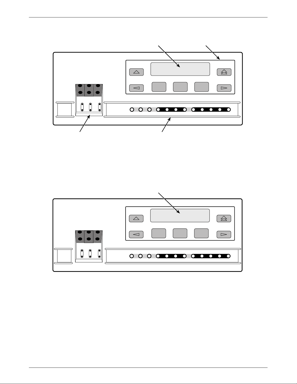
3160/3164 DSU/CSU Front Panel
The 3160/3164 DSU/CSU front panel contains,
• One 2-line, 16-alphanumeric character per line
liquid crystal display (LCD)
• One 7-button keypad (three Function and four
directional keys)
• Twelve light-emitting diodes (LEDs), five of which
are shared between the DSX-1 (DTE) Drop/Insert
T1 interface and the data ports.
Six test jacks
•
The front panel is shown in Figure 1-1.
Two link layer protocols are supported for connection
to an external SNMP manager or network device,
Point-to-Point Protocol (PPP) and Serial Line Internet
Protocol (SLIP). The protocol type is configurable using
the configuration options (see Appendix C, Configuration
Options).
Communication with the external SNMP management
system can be through a serial connection on either the
COM port or the MODEM port. Only one port can be
configured as the management link at one time. However,
the 3160/3164 DSU/CSU can be accessed simultaneously
by either the front panel or front panel emulation software
on one port, and an SNMP management system on the
other port. Users on the external SNMP manager can issue
“Get” and “Set” SNMP commands to an object in the
SNMP database maintained by the DSU/CSU. The
DSU/CSU can be configured to issue SNMP traps to the
SNMP manager under various alarm conditions.
1-4 December 1996 3160-A2-GB22-10
3160/3164 DSU/CSU Rear Panel
The 3160/3164 DSU/CSU rear panel contains the
connectors required for the operation of the DSU/CSU
(Figures 1-3 and 1-4). The connectors and their functions
are listed in Table 1-1.
Page 19
Introduction
3
1
LCD
ACCULINK
F1 F2 F3
NET
MON
EQPT
MON
OK
FAIL TEST SIG OOF ALRM
NET
In
OutInOutInOut
TEST JACKS LEDs
Figure 1-1. 3160 DSU/CSU Front Panel
KEYPAD
EER SIG ALRM PDVOOF BPV
NETWORK RXD
DTR TXD CTS RTS
496-14539-0
ACCULINK
3164
NET
NET
MON
In
OutInOutInOut
LCD
F1 F2 F3
EQPT
MON
OK
FAIL TEST SIG OOF ALRM
NETWORK RXD
Figure 1-2. 3164 DSU/CSU Front Panel
EER SIG ALRM PDVOOF BPV
DTR TXD CTS RTS
496-14566-0
1-53160-A2-GB22-10 December 1996
Page 20

ACCULINK 316x DSU/CSU
Figure 1-3. 3160 DSU/CSU Rear Panel
Figure 1-4. 3164 DSU/CSU Rear Panel
1-6 December 1996 3160-A2-GB22-10
Page 21

Table 1-1
Models 3160/3164 DSU/CSUs Rear Panel Connectors
Introduction
Connector Name
POWER A modular connector that supplies power to the DSU/CSU.
AUX PORT An auxiliary communications port for future use.
COM PORT A communications port that provides access to the front panel from a locally
connected PC. The port can also be used to connect a terminal for an async
terminal interface, an ASCII terminal or printer for reporting alarm messages, or to
support an SNMP management link. The connector is an 8-pin, keyed modular jack.
MODEM An RJ11 connector for a 2-wire VF line used to connect the integral modem.
Provides access to the front panel from a remotely connected PC. The port can also
be used to connect a remote terminal for an async terminal interface or an ASCII
terminal or printer for reporting alarm messages, or to support an SNMP
management link.
DTE (DSX-1) A DB15 socket, screw-type connector for DTE equipment.
NETWORK An RJ48C, unkeyed modular jack that provides connection to the T1 network.
CLOCK IN A connector used to attach an external clock to the DSU/CSU.
PORT 1—4 A DB25 (EIA 530A) connector used to connect the customer’s synchronous data
DTE.
Function
1-73160-A2-GB22-10 December 1996
Page 22
ACCULINK 316x DSU/CSU
Carrier-Mounted Model 3161 DSU/CSU
The
3161 DSU/CSU is a circuit card that is installed
into the 3000 Series Carrier. A single carrier can house up
to 16 DSU/CSUs; the DSU/CSUs are controlled by the
carrier’s Shared Diagnostic Control Panel (SDCP), which
can control up to eight carriers. Rear panel connections
are provided by the Auxiliary Backplane, which is
installed on the rear of the carrier.
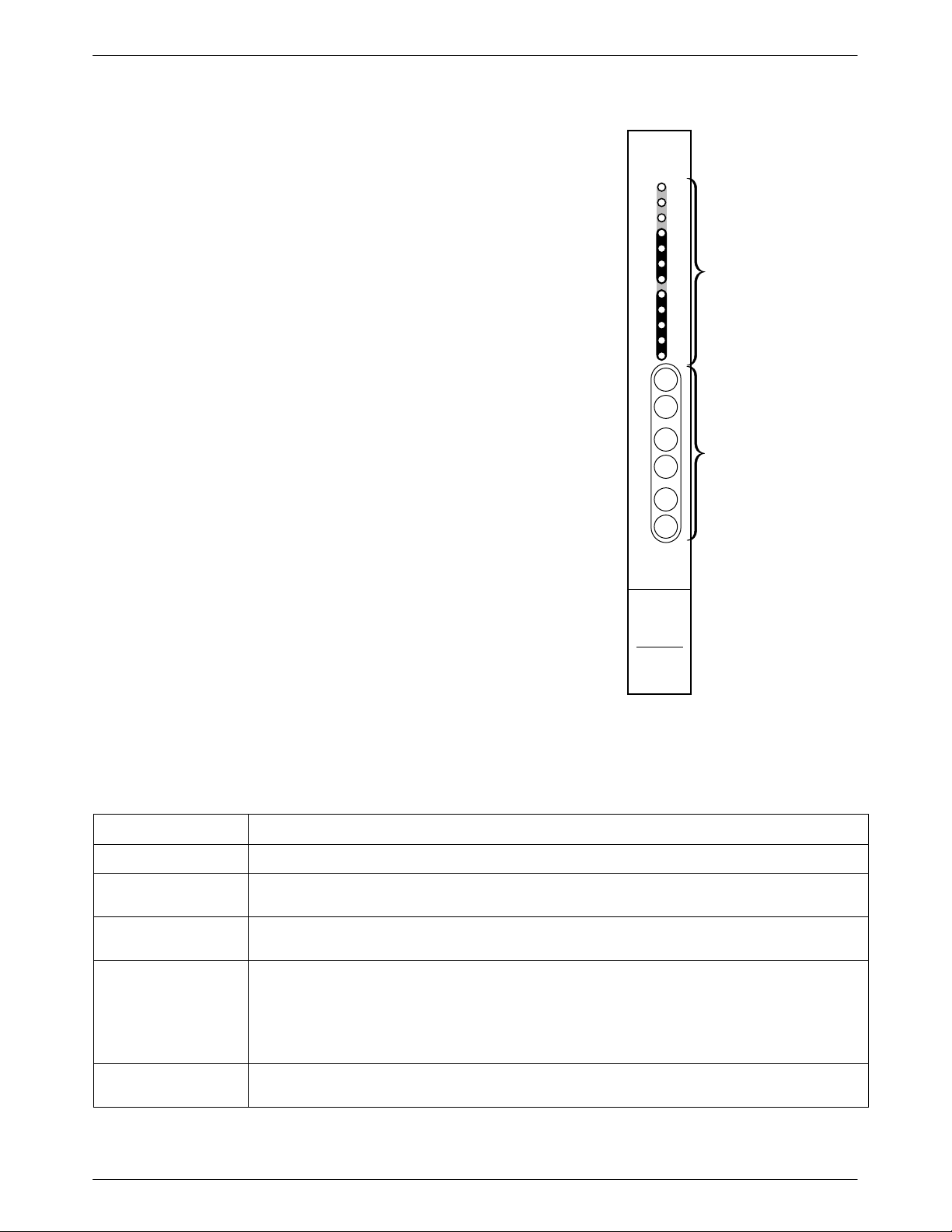
Model 3161 Front Panel Functions
The
twelve LEDs and six test jacks provided on the
faceplate of the Model 3161 DSU/CSU are the same in
function as those provided on the front panel of the
3160/3164 DSU/CSU (see Figure 1-5). Other front panel
functions, including a keypad and LCD, are provided by
the SDCP of the 3000 Series Carrier
. These SDCP
functions are described in the COMSPHERE 3000 Series
Carrier Installation Manual
.
Model 3161 DSU/CSU Rear Panel
Select
Net
DTR
TXD
RXD
CTS
RTS
In
Net
Out
In
Net
Mon
Out
In
Eqp
Mon
Out
OK
Fail
Test
Sig
OOF
Alrm
EER
Sig
OOF
Alrm
PDV
BPV
12
LEDS
6
TEST
JACKS
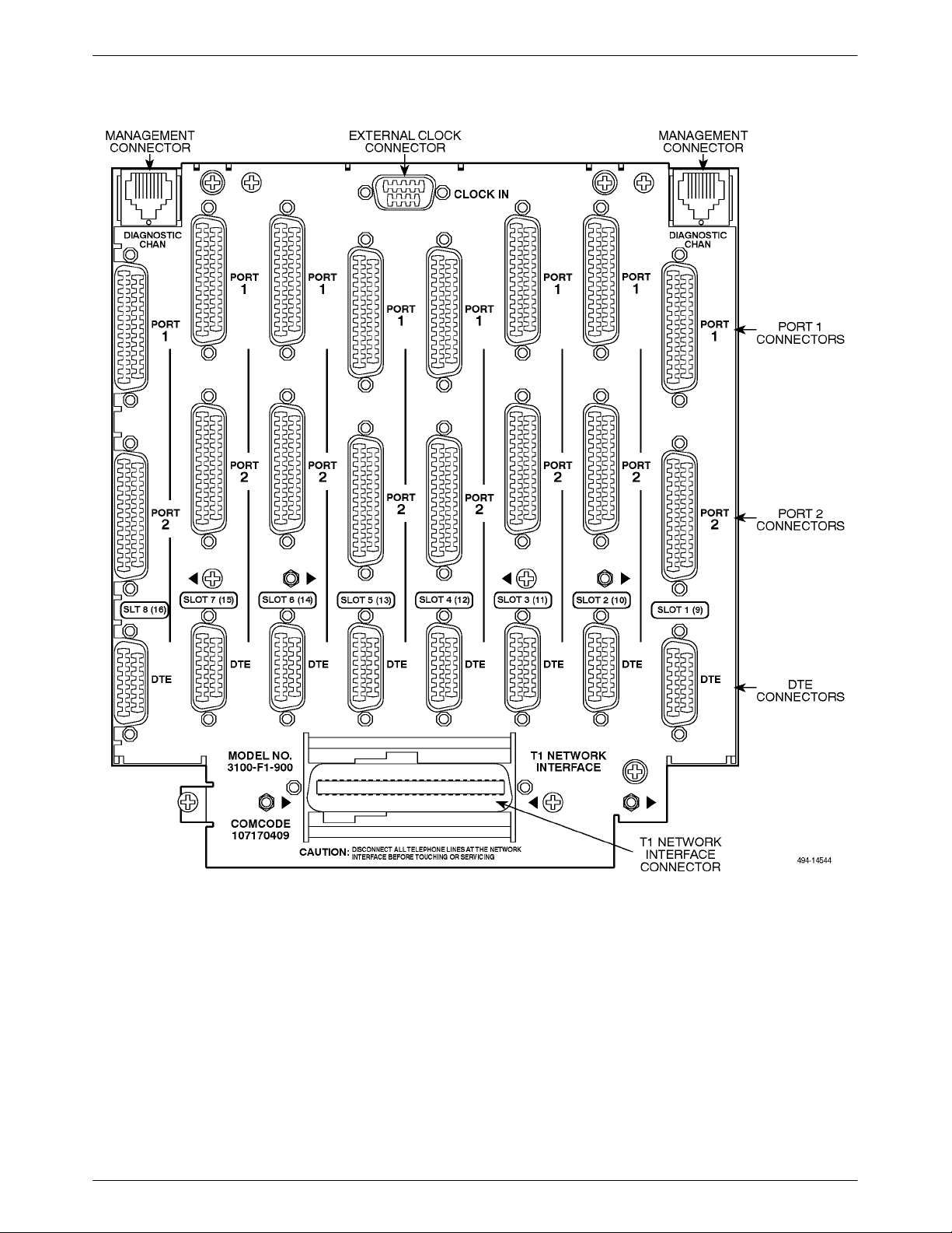
The
Auxiliary Backplane, which is installed on the rear
of the 3000 Series Carrier
, contains the connectors needed
for operation of the 3161 DSU/CSU (see Figure 1-6). This
Auxiliary Backplane can be used by both 3151 CSUs and
3161 DSU/CSUs; some of the connectors shown (i.e., data
port and external clock connectors) apply only to 3161
DSU/CSU applications. The 3161 DSU/CSU connectors
and their functions are listed in Table 1-2.
DSU/CSU
3161
496-14543-01
Figure 1-5. 3161 DSU/CSU Faceplate
Table 1-2
Auxiliary Backplane Connectors
Connector Name
DTE A DB15 socket, screw-type connector for T1 DSX-1 (DTE) equipment.
NETWORK A 50-pin, RJ48H plug that provides connection to the T1 network for all eight slots supported by
the Auxiliary Backplane.
CLOCK IN A DB9 socket that attaches an external clock to the DSU/CSU. The external clock provides timing
for up to eight slots. Each Auxiliary Backplane must have its own external clock input.
PORTS 1 and 2 A DB25 socket (EIA-530A) that connects to the synchronous data DTE.
The Port 2 DB25 socket connector allows one slot in the carrier to be configured as the COM port,
which replaces the functionality of the second data port. The COM port is a communications port
that provides access to Front Panel Emulation software running on a locally connected PC or
async terminal connection for DSU/CSU devices on an Async Terminal Interface.
Function
MANAGEMENT An 8-pin modular jack that provides management connectivity between Auxiliary Backplanes in a
carrier.
1-8 December 1996 3160-A2-GB22-10
Page 23
Introduction
Figure 1-6. Auxiliary Backplane
1-93160-A2-GB22-10 December 1996
Page 24

Installation
Overview 2-1. . . . . . . . . . . . . . . . . . . . . . . . . . . . . . . . . . . . . . . . . . . . . . . . . . . . . . . . . . . . . . . . . . . . . . . . . .
Planning 2-1. . . . . . . . . . . . . . . . . . . . . . . . . . . . . . . . . . . . . . . . . . . . . . . . . . . . . . . . . . . . . . . . . . . . . . . . . .
Box Contents 2-5. . . . . . . . . . . . . . . . . . . . . . . . . . . . . . . . . . . . . . . . . . . . . . . . . . . . . . . . . . . . . . . . . . . . . . .
Important Safety Instructions 2-5. . . . . . . . . . . . . . . . . . . . . . . . . . . . . . . . . . . . . . . . . . . . . . . . . . . . . . . . . .
Quick Start Procedure 2-5. . . . . . . . . . . . . . . . . . . . . . . . . . . . . . . . . . . . . . . . . . . . . . . . . . . . . . . . . . . . . . . .
Optional Power Selection 2-6. . . . . . . . . . . . . . . . . . . . . . . . . . . . . . . . . . . . . . . . . . . . . . . . . . . . . . . . . . . . .
Installing the +24 Vdc Power Supply 2-6. . . . . . . . . . . . . . . . . . . . . . . . . . . . . . . . . . . . . . . . . . . . . . . . .
Installing the Single –48 Vdc Power Supply 2-7. . . . . . . . . . . . . . . . . . . . . . . . . . . . . . . . . . . . . . . . . . . .
Installing the Redundant –48 Vdc Power Supply 2-8. . . . . . . . . . . . . . . . . . . . . . . . . . . . . . . . . . . . . . . .
Power-Up Self-Test 2-9. . . . . . . . . . . . . . . . . . . . . . . . . . . . . . . . . . . . . . . . . . . . . . . . . . . . . . . . . . . . . . . . . .
Selecting a Model 3161 DSU/CSU 2-10. . . . . . . . . . . . . . . . . . . . . . . . . . . . . . . . . . . . . . . . . . . . . . . . . . . . . .
DSU/CSU Identity 2-10. . . . . . . . . . . . . . . . . . . . . . . . . . . . . . . . . . . . . . . . . . . . . . . . . . . . . . . . . . . . . . . . . .
Establishing Access Security on a Port 2-12. . . . . . . . . . . . . . . . . . . . . . . . . . . . . . . . . . . . . . . . . . . . . . . . . . .
Setting/Changing a Password 2-12. . . . . . . . . . . . . . . . . . . . . . . . . . . . . . . . . . . . . . . . . . . . . . . . . . . . . . . . . .
3160/3164 DSU/CSU Cabling 2-14. . . . . . . . . . . . . . . . . . . . . . . . . . . . . . . . . . . . . . . . . . . . . . . . . . . . . . . . .
Factory Default Configuration Options 2-16. . . . . . . . . . . . . . . . . . . . . . . . . . . . . . . . . . . . . . . . . . . . . . . . . .
Installing Front Panel Emulation Software 2-16. . . . . . . . . . . . . . . . . . . . . . . . . . . . . . . . . . . . . . . . . . . . . . . .
Enabling/Disabling the Front Panel 2-17. . . . . . . . . . . . . . . . . . . . . . . . . . . . . . . . . . . . . . . . . . . . . . . . . . . . .
2
Overview
This chapter contains information for installing your
3160/3164 DSU/CSU: planning considerations, a list of
what you should receive in the DSU/CSU box, and a
Quick Start section for experienced DSU/CSU users who
have no special installation or operation requirements.
More detailed installation instructions are also provided,
including cabling and software configuration option
information.
Installation instructions for the 3161 DSU/CSU are
located in the
General Information Guide.
ACCULINK 3151 CSU and 3161 DSU/CSU
Planning
The ACCULINK 316x DSU/CSU is designed to
provide an interface between the T1 digital network and
the Customer Premise Equipment (CPE). The DSU/CSU
must be connected to the CPE through its DSX-1 (DTE)
Drop/Insert port or one of the data ports, and then to the
network through the DSU/CSU Network Interface (NET)
port. The most common configurations for the 316x
DSU/CSU are:
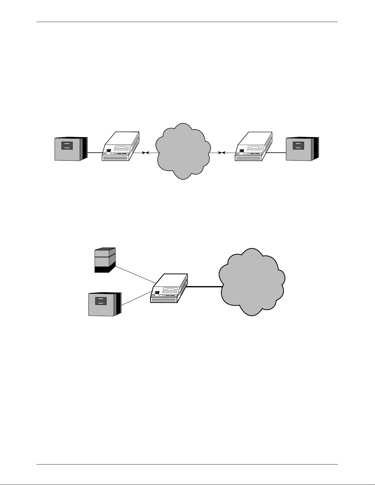
• Point-to-point LAN interconnection (Figure 2-1).
Shared access to network-based services
•
(Figure 2-2 ).
• Multiport T1 DSU/CSU in a fractional
T1 network (Figure 2-3).
• Central-site T1 termination for Model 3161
DSU/CSUs (Figure 2-4).
Both voice and data applications are supported.
2-13160-A2-GB22-10 December 1996
Page 25
ACCULINK 316x DSU/CSU
3
3
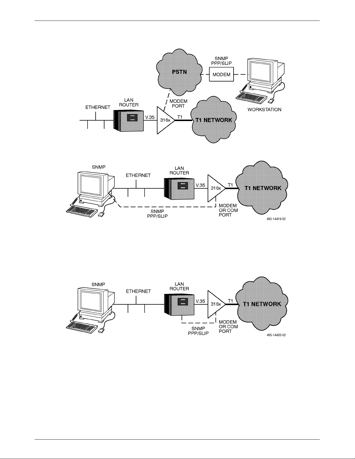
In addition, a 3160 DSU/CSU, acting as an SNMP
agent, can be connected to and managed from an SNMP
management system in one of two ways:
• Serial connection via the COM or MODEM port to
an SNMP management system using either
Point-to-Point Protocol (PPP) or Serial Line
Internet Protocol (SLIP) (Figure 2-5).
T1
NETWORK
LAN
ROUTER
ACCULINK
3160/3164 DSU/CSU
Figure 2-1. Example Point-to-Point Configuration
• Serial connection via the COM or MODEM port
(using PPP or SLIP) through a network device (e.g.,
router) that supports IP routing to the network
management system (Figure 2-6).
T1
ACCULINK
3160/3164 DSU/CSU
LAN
ROUTER
496-14296-0
PBX
NETWORK
SERVICES
DSU/CSU
LAN
ROUTER
496-14312-0
Figure 2-2. Example Shared Access to Network-Based Services Configuration
2-2 December 1996 3160-A2-GB22-10
Page 26
T1
1
Installation
LAN
ROUTER
ACCULINK
3160/3164 DSU/CSU
T1
FRACTIONAL T1
NETWORK
LAN
ROUTER
T1
ACCULINK
3160/3164 DSU/CSU
ACCULINK
3160/3164 DSU/CSU
ROUTERS
Figure 2-3. Multiport T1 DSU/CSU in a Fractional T1 Network Configuration
LAN
496-14313a-0
Figure 2-4. Central-Site T1 Termination Configuration
2-33160-A2-GB22-10 December 1996
Page 27
ACCULINK 316x DSU/CSU
Figure 2-5. Serial Connection to SNMP
Figure 2-6. Serial Connection through a Router to SNMP
2-4 December 1996 3160-A2-GB22-10
Page 28

Installation
Box Contents
The 3160/3164 DSU/CSU product arrives in a single
box and should contain the following:
•
One 3160/3164 DSU/CSU standalone unit
• One 14.5 foot VF cable
• One power transformer
• One
• One
Please refer all servicing to qualified personnel. The
Download front panel branch is dedicated to DSU/CSU
service and maintenance and is not intended for use by the
customer.
The 3100 Series Front Panel Emulation software is
available separately and is described in the
Emulation Software Installation
chapter.
ACCULINK 3160/3164 DSU/CSU Refer
Card
ACCULINK 316x Data Service Unit/Channel
Service Unit Operator’s Guide
Front Panel
section later in this
ence
Important Safety Instructions
HANDLING PRECAUTIONS
FOR
STA
TIC-SENSITIVE DEVICES
This product is designed to protect
sensitive components from damage
due to electrostatic discharge (ESD)
during normal operation. When
performing installation procedures,
however, take proper static control
precautions to prevent damage to
equipment. If you are not sure of the
proper static control precautions,
contact your near
representative.
For a complete listing of the safety instructions, see the
Important Safety Instructions
est sales or service
section earlier in this guide.
Quick Start Procedure
The following procedure is for experienced DSU/CSU
users who are familiar with the 3160/3164 DSU/CSU
installation process and have no special requirements for
their application.
Read and follow all warning notices and instructions
marked on the 316x DSU/CSU or included in this guide.
NOTE
The Download command is for
use by service personnel only.
Loss of primary data could result
from improper use.
1. Attach the power cord to the rear of the DSU/CSU
and the other end to a grounded 115 Vac power
outlet.
2. Attach the 3160/3164 DSU/CSU network
connection to the T1 network using the
appropriate cable. Attach the 3160/3164
DSU/CSU to the CPE via the DTE (DSX-1)
and/or ports connectors. Adapter cables are
available which allow RS449 or V
be supported from the EIA 530A connector on the
rear panel. Refer to Appendix H, Equipment List.
See the
in this chapter for more cabling information.
3. Power on the DSU/CSU to perform the power-up
self-test. See the
in this chapter for more information.
4. To perform front panel emulation, connect the
cable from the PC to the COM port on the rear
panel of the DSU/CSU. To perform device
management from an async terminal, connect the
terminal to the COM port (or for dial-in access,
the modem port) on the rear panel of the
DSU/CSU. See the 3160/3164 DSU/CSU
section later in this chapter for more cabling
information.
3160/3164 DSU/CSU Cabling
Power-Up Self-Test
.35 devices to
section later
section later
Cabling
2-53160-A2-GB22-10 December 1996
Page 29
ACCULINK 316x DSU/CSU
5. If you intend to manage the 3160/3164 DSU/CSU
with SNMP
port (as appropriate for your configuration). Then,
configure the SNMP management link. See
Chapter 3, Operation,
Configuration Options,
6. If you do not intend to use the DTE Drop/Insert
T1 port, disable it using the configuration
procedures in Chapter 3,
Appendix C, Configuration Options
setting for this port is Enabled.)
7. The Factory 1 configuration for ESF framing
format and B8ZS line coding format is the default
configuration and is appropriate for most
networks. If this configuration does not work for
you, try the Factory 2 configuration for D4
framing format and AMI line coding format. To
further customize configuration options, refer to
Configuring the DSU/CSU section in
the
Chapter 3, Operation
Configuration Options
8. Verify that the DSU/CSU is functional by
observing that the OK
LEDs are lit.
9.
Configure the ports and channels you intend to use
and assign channels to the network interface. To
do so, refer to
, cable either the COM or MODEM
and Appendix C,
for more information.
Operation
, and to Appendix C,
.
and
NETWORK SIG
Configuring the DSU/CSU
, and
. (The default
section
in Chapter 3, Operation
Configuration Options
, and to Appendix C,
.
Optional Power Selection
Using the optional dc power cable, the 3160/3164
DSU/CSU is capable of operating on either a +24 Vdc
power source, –
redundant source batteries (for power backup). T
the power, choose one of the following power supply
types.
48 Vdc single source battery
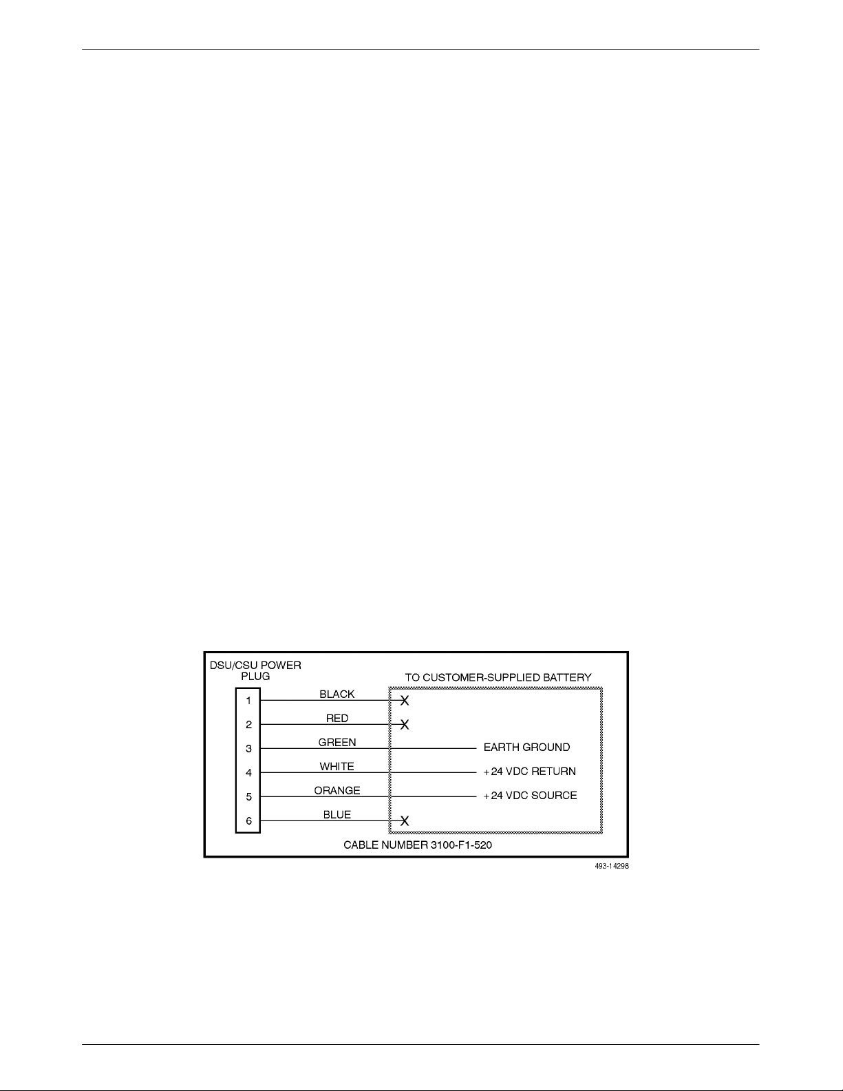
Installing the +24 Vdc Power Supply
To
install the 3160/3164 DSU/CSU using a +24 Vdc
power supply, refer to Figure 2-7 and use the following
procedure.
o install the +24 Vdc power supply
T
1. Connect the green wire to a suitable earth ground.
2. Connect the white wire to the +24 Vdc return.
Connect the orange wire to the +24 Vdc source.
3.
4. Cut the black, red and blue wires off at the outer
insulation.
5. Plug the power connector into the 3160/3164
DSU/CSU.
, or –
48 Vdc
o select
,
Figure 2-7. +24 Vdc Power Supply Pinouts
2-6 December 1996 3160-A2-GB22-10
Page 30
Installation
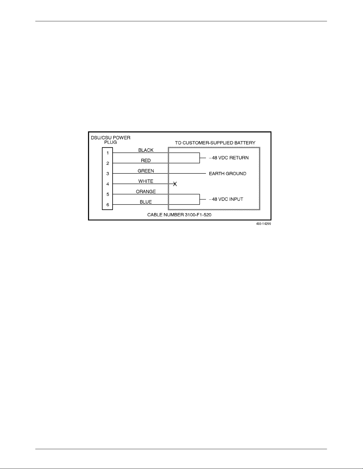
Installing the Single –ā48 Vdc Power Supply
To
install the 3160/3164 DSU/CSU using a single
source –
the following procedure.
48 Vdc power supply, refer to Figure 2-8 and use
o install the –
T
1.
Connect the black and red wires to the –48 Vdc
48 Vdc single source power supply
return source.
,
2. Connect the green wire to a suitable earth ground.
3.
Connect the orange and blue wires to the –ā48 Vdc
input source.
4. Cut the white wire off at the outer insulation.
5. Plug the power connector into the 3160/3164
DSU/CSU.
Figure 2-8. –ā48 Vdc Single Source Power Supply Pinouts
2-73160-A2-GB22-10 December 1996
Page 31

ACCULINK 316x DSU/CSU
Installing the Redundant –ā48 Vdc Power
Supply
To install the 3160/3164 DSU/CSU using a redundant
– 48 Vdc power supply, refer to Figure 2-9 and use the
following procedure.
To install the redundant –48 Vdc power supply,
1. Connect the black wire to the –48 Vdc return
source B.
2. Connect the red wire to the –48 Vdc return
source
A.
3. Connect the green wire to a suitable earth ground.
4. Connect the orange wire to the –48 Vdc input
source B.
5. Connect the blue wire to the –48 Vdc input
source A.
6. Cut the white wire off at the outer insulation.
7. Plug the power connector into the 3160/3164
DSU/CSU.
Figure 2-9. –ā48 Vdc Redundant Source Power Supply Pinouts
2-8 December 1996 3160-A2-GB22-10
Page 32

Power-Up Self-Test
After you connect the 3160/3164 DSU/CSU to a power
outlet, the power-up self-test is performed to ensure that
the unit is in good working order. The DSU/CSU
performs this test on itself upon power-up or after a device
reset unless it has been disabled by the Self-T
configuration option (see Appendix C,
Options).
The 3161 DSU/CSU performs the same power-up
self-test except that progress is not reported on the SDCP
during the test. However, you can use the Self-T
command to display the status of the test (see
section in Chapter 3,
Health
Operation
est
Configuration
est Health
Self-Test
).
Installation
3.
If the self-test is successful, the Passed screen
appears for one second, the Fail LED is turned Off
and the OK LED lights.
Self-Test:
Passed
F1
F2
F3
The self-test includes a basic CPU test, a limited RAM
test, a code checksum test, and basic verification tests of
its internal components. The front panel LCD displays the
progress and pass/fail status of these power
The power
-up self-test consists of the following steps:
-up tests.
1. Once the DSU/CSU is plugged in, the In Progress
screen appears and the Fail LED blinks ON and
Off continuously.
Self-Test:
P
rogress
In
F1
F2
F3
2. All the LEDs then start to flash simultaneously in
the pattern twice ON, then Off. Then, the LCD
begins to flash characters and numbers in the same
pattern, alternating with the flashing LEDs.
If the self-test fails, the Failed screen appears for
five seconds. The Fail LED lights. The DSU/CSU
continues to try to operate. If you are in doubt
about the results of the self-test, use the Self-Test
Health command to display the status of this test
(see
Self-T
est Health
section in Chapter 3,
Operation).
Self-Test:
Failed nnnnnnnn
F1
4. The
top-level menu screen appears.
DS
F2
U E
F3
SF
Stat Test Cnfig
F1
F2
F3
2-93160-A2-GB22-10 December 1996
Page 33

ACCULINK 316x DSU/CSU
Differences
Using the Async T
erminal: To monitor the
self-test from the async terminal, select Health, Test
, and
Self T
Status
est Results
from the main/status menu.
The full screen display capacity provides a complete test
results screen that includes the self-test results.
Figure 2-10 shows an example of this screen.
Customer ID: New Cust
Health and Status
DSU Operational
LOS at Net
LOS at DTE
OOF at Net
OOF at DTE
AIS at Net
AIS at DTE
EER at Net
Yellow at Net
Yellow at DTE
Master Clock Fail
SNMP Link Down
Selftest failed
DevFail yyyyyyyy
Download failed
Alm Retry Disab
Test in progress
Modem Connected
Refresh Down UP Main Previous Cntrl–x to Disconnect
main/status/health_and_status
Model: ACCULINK XXXX
Self Test Results
CPU fail
Device fail
B8ZS/LOS fail
Modem fail
DTE T1 fail
Alarm fail
LCD fail
NET T1 fail
Memory fail
DSU fail
DSU Port 1 fail
DSU Port 2 fail
DSU Port 3 fail
DSU Port 4 fail
Unknown Exp Dev
Failure xxxxxxxx
Passed
Test Status
No Test Active
LLB Test Active
PLB Test Active
DLB Test Active
RLB Test Active
DCLB on Port n
DTLB on Port n
QRSS Test Active
1–8 Test Active
QRSS on Port n
511 on Port n
Monitoring QRSS
Monitoring QRSS, Port n
Monitoring 511, Port n
DLB Test, Extrn
Lamp Test Active
DSU/CSU Identity
The identity of the 316x DSU/CSU (serial number,
model number, software revision level, hardware revision
level, and customer ID) is available through the Status
branch of the front panel menu (see Appendix A, Front
Panel Menu).
The customer ID is the only identity number you can
change.
To display the DSU/CSU’
s identity
1. Press F1 to select Status from the top-level menu
screen.
DS
Stat Test Cnfig
F1
2. Press the
key three times on the Status screen
to bring the ID selection onto the front panel LCD.
U E
F2
,
SF
F3
Figure 2-10. Health and Status Results Screen
If
a test fails,
fail
appears next to the component
reporting the failure.
To perform a power or reset of the device, see
Resetting the CSU/DSU
in Chapter 4.
Selecting a Model 3161
DSU/CSU
Use
the SDCP when accessing a specific circuit card
installed in the 3000 Series Carrier.
T
o access a 3161 DSU/CSU,
1.
Press
Select on the SDCP.
2. Enter a valid carrier and slot address. The green
indicator on the selected 3161 DSU/CSU
OK
should flash. (It should be the only OK indicator
flashing in the cabinet.)
Press
3.
Select again. The display on the SDCP
should show the last menu item displayed, or in
the case of a new installation, the top-level menu
on the selected circuit card.
Status:
DevHS STest Perf
F1
F2
F3
3. Press F3 to select ID from the Status screen.
Status:
TStat LED ID
F1
F2
F3
2-10 December 1996 3160-A2-GB22-10
Page 34

Installation
4. The following screens appear in the order listed
each time you press the
key
.
Identity:
Ser=xxxxxxx
F1
F2
F3
Identity:
Mod=xxxx-xx-xxx
F1
F2
F3
Identity:
Cust ID=xxxxxxxx
F1
F2
F3
To change the customer ID,
Press the
1.
key on the top-level menu to bring
the Ctrl branch onto the front panel LCD.
DS
U E
SF
Stat Test Cnfig
F1
F2
F3
2. Press F3 to select Ctrl from the top-level menu
screen.
DS
U E
SF
Test Cnfig Ctrl
F1
F2
F3
3. Press the key on the Ctrl screen until the CID
selection appears on the front panel LCD.
Identity:
SRev=xx.xx.xx
F1
F2
Identity:
CCA1=xxx
F1
F2
Identity:
CCA2=xxx
F1
F2
F3
F3
F3
Control:
Call Rel LED
F1
4.
Press F2 to select CID.
Control:
Reset CID
F1
5. Use the
and
under the desired character
character before the
next space to the right. The
destructive.
CustID=xxxxxxxx
Up Down Save
F2
P
F2
F3
assword
F3
keys to position the cursor
. Y
ou must enter a
moves the cursor to the
key is not
F1
F2
F3
2-113160-A2-GB22-10 December 1996
Page 35

ACCULINK 316x DSU/CSU
6. Enter the desired ID. Press F1 (Up) and F2
(Down) to scroll up and down through the valid
characters/numbers for the customer ID. Valid
characters are 0 through 9, #, -, ., /, A to Z
, and
blank space. Press F3 (Save) to save the ID.
CustID=xxxxxxxx
Up Down Save
F1
Differ
ences Using the Async T
F2
F3
erminal: The customer
ID selection is found in the main/control/miscellaneous
control options menu. Select Customer Identification
Name/Number from that menu.
Establishing Access Security
on a Port
Although
required as a factory default. If used, it ensures access
security before device control is passed to a PC or
terminal connected to a port. The password configuration
option can be individually set for the COM or MODEM
port, or both if security is needed on both port types. The
default is none. From the front panel, set this
configuration option using the Control branch. Select
cnfig→edit→user→password
separately
Password.
Differ
set in the main/configuration/edit/user screen. Figure 2-11
shows an example of this screen.
the password feature is available, it is not
. The password itself is set
. Refer to the section
ences Using the Async T
Setting/Changing a
erminal
: The password is
Customer ID: New Cust
Front Panel Access: _____
Front Panel Pass-Through: _____
Password Mode: _____
Communications Port Modem Port
Use: _____
Type: _____
Character Length: _____
Rate: _____
Parity: _____
Stop Bits: _____
Save Edit Main Previous Cntrl–x to Disconnect
main/configuration/edit/user
Model: ACCULINK XXXX
User
Self Test: _____
Dial-In Access: _____
Character Length: _____
Long Space Disconnect: _____
Use: _____
Type: _____
Rate: _____
Parity: _____
Stop Bits: _____
Figure 2-11. Setting the Password Option
On
this screen, set the
Password Mode
field as
appropriate.
Setting/Changing a Password
For 3160/3164 DSU/CSUs, you have the option of
setting a password for security when receiving a call or
the COM port connection is established. Unless you
specify otherwise, the password is null.
NOTE
To cancel a password operation,
press either the or key
before saving.
2-12 December 1996 3160-A2-GB22-10
Page 36

To
set a password,
1.
Press the
key on the top-level menu screen to
bring the Ctrl branch onto the front panel LCD.
6. Enter
the desired password. Press F1 (Up) and
F2 (Down) to scroll up and down through the
valid characters/numbers for the password. Valid
password characters are
and
/.
0–9, a–z, A–Z, #, –, .,
Installation
DS
U E
SF
Stat Test Cnfig
F1
F2
F3
2. Press F3 to select Ctrl from the top-level menu
screen.
DS
U E
SF
Test Cnfig Ctrl
F1
F2
F3
3. Press the key on the Ctrl screen until the
Passwd selection appears on the front panel LCD.
Control:
Call Rel LED
F1
F2
F3
Passwd: xxxxxxxx
Up Down Save
F3
7. Press
F1
F2
F3 (Save) to save the password.
Passwd: xxxxxxxx
Up Down Save
F3
o set the
Differences
Using the Async T
password, select
F1
F2
erminal: T
miscellaneous/control/options in the
main/control screen. This screen displays the prompt
Change Password?
the Password
If you enter yes
and
Re-enter Password
, the screen displays
fields as shown in
Figure 2-12.
4.
Press F3 to select Passwd.
Control:
Reset CID
F1
5. Use the
and
under the desired character
character before the
next space to the right. The
destructive.
Passwd: _
Up Down Save
F1
P
asswd
F2
F3
keys to position the cursor
. Y
ou must enter a
moves the cursor to the
key is not
F2
F3
Customer ID: New Cust
Miscellaneous Control Options
Front Panel LED Display:_____
Customer Identification Name/Number:_____
Save Main Previous Cntrl–x to Disconnect
main/control/miscellaneous
Model: ACCULINK XXXX
Change Password?_____
Password:_____
Re-enter Password:_____
Yes
Figure 2-12. Password Configuration Screen
2-133160-A2-GB22-10 December 1996
Page 37

ACCULINK 316x DSU/CSU
3160/3164 DSU/CSU Cabling
The
3160/3164 DSU/CSU is supplied with an ac power
transformer and a VF cable for the integral modem. You
must provide the DTE cable to connect the DTE to the
DSU/CSU.
Optional cables you can order from the company are
the following:
• T1 line interface cable.
Data port cables (DB25 to V
•
RS449).
• COM port cable to locally connect an ASCII
terminal/printer or async terminal.
.35 and DB25 to
COM port cable to locally connect a PC.
•
• A dc voltage power cable for the –
redundant source, –
+24 Vdc power source.
Figure 2-13 illustrates possible cabling configurations.
In Canada, an RJ48C-to-CA81A Adapter Cable (Feature
Number 3100-F1-510) must be used to connect the
T1 network. See Appendix D,
cable information. See Appendix H, Equipment List, for
part number information. See the COMSPHERE
3000 Series Carrier Installation Manual
DSU/CSU cabling information.
48 Vdc single source, and
Pin Assignments
48 Vdc
, for more
for Model 3161
2-14 December 1996 3160-A2-GB22-10
Page 38

Installation
Figure 2-13. 3160/3164 DSU/CSU Cabling Configurations
2-153160-A2-GB22-10 December 1996
Page 39

ACCULINK 316x DSU/CSU
Factory Default Configuration
Options
The 316x DSU/CSU arrives with two preset factory
default configuration settings. These settings are based on
the following:
• Factory 1 – ESF framing format with B8ZS line
coding format for both the network and the DSX-1
Drop/Insert T1 interfaces. Data ports are
unassigned.
• Factory 2 – D4 framing format with AMI line
coding format for both the network and the DSX-1
Drop/Insert T1 interfaces. Data ports are
unassigned.
If neither of the factory default settings support your
network’s configuration, you can customize the
configuration options to better suit your application. Refer
Configuring the DSU/CSU
to the
Operation,
more information.
and Appendix C,
section in Chapter 3,
Configuration Options
, for
Installing Front Panel
Emulation Software
To install Front Panel Emulation software,
1. Insert the diskette into the appropriate drive.
2. Select File from Program Manager.
Choose Run...
3.
4. Type the letter of the drive being used by the
diskette, followed by a colon.
5. TYPE: INSTALL
6. PRESS: ENTER
An Information screen appears. Choose Continue
7.
to continue the installation.
8. Type the letter of the destination drive, followed
by a colon (default is C:), then the appropriate
directory name (default is C:\FRONTPAN).
The Front Panel Emulation software is supplied on a
3.5-inch diskette formatted as 1.44 Mb, double-sided,
high-density, write-protected, with 15 sectors per track,
80 tracks per side, 96 tracks per inch.
This software must be installed on either a 286 or
W
higher PC with Microsoftr
higher already installed, and MS-DOSr 3.3 or higher
VGA color monitor with VGA adapter (or higher
resolution) is required. A mouse is also required. The
following procedures must be performed in the Windows
environment.
indowst
Release 3.1 or
. A
If the selected directory already exists, the
message
Do you want to overwrite the directory?
appears.
If the selected directory is new
specified directory does not exist. Do you want
to create the directory?
9.
Select Yes. A confirmation screen appears. Select
Install to continue the installation.
A Setup Completed screen appears. Select
10.
Continue. The Program Manager screen appears
with the Front Panel icon.
See the
Chapter 3, Operation, for information about the Front
Panel Emulation operation.
The specified dir
Starting Up a Front Panel Emulation
ectory alr
, the message
appears.
eady exists.
section in
The
2-16 December 1996 3160-A2-GB22-10
Page 40

Installation
Enabling/Disabling the Front
Panel
You can enable or disable the display of data through
the front panel. This feature is useful for ensuring that
other users do not inadvertently change the device’s
configuration options while you are using the PC or async
terminal interface. The factory default is enable.
NOTE
If you disable the front panel, be
sure not to alter the options for
using the PC or Async terminal
interface. If this happens, you lose
the ability to communicate with
the device. You will need to
contact your service
representative.
To enable or disable the front panel:
1. Press F3 to select Cnfig from the top-level menu
screen.
3. Press F1 to select Edit.
Choose Funct:
Edit Save
F1
F2
F3
4. Press the key from the Edit screen to display
the User selection.
Edit:
DTE Port NET
F3
5.
Press F3 to select User
F1
F2
.
Edit:
Chan Gen User
F1
F2
F3
DS
U E
SF
Stat Test Cnfig
F1
F2
F3
2. Select the configuration option set to be copied
into the Edit area by using the appropriate
function key
. Use the scroll keys, if necessary
Load from:
Activ Cust Fact1
F1
F2
F3
6. Press the F1 (Next) key until the front panel
access configuration option appears.
Self-Test:Enab
Next Enab Disab
.
F1
F2
F3
7. Press F2 to enable the front panel or F3 to disable
the front panel.
FP Access:
Next Enab Disab
F1
F2
F3
2-173160-A2-GB22-10 December 1996
Page 41

ACCULINK 316x DSU/CSU
3160/3164 DSU/CSU User
Interface Access Security
The
user interface access security option allows you to
limit access to the 3160/3164 DSU/CSU to display-only
and non-intrusive functions. The user access security
option is not available for 3161 DSU/CSUs.
Level 1 (Lvl1) access security allows access to all
functions available through the menu tree. This is the
default setting.
Level 2 (Lvl2) access security restricts access to only
those functions that cannot affect the operation of the
DSU/CSU in any way
. At this level,
Y
ou can only reach the screen that controls security
access using the front panel; you cannot access this option
using front panel emulation, async terminal, or the modem
interface.
The procedure for changing user interface access
security levels appears on the following tear-out page.
• None of the functions in the T
are available.
• All functions on the Stat branch are available.
• All functions on the Cnfg branch are available for
, but they cannot be used to save to a
display
configuration (Active, Cust, Fact1, or Fact2).
est or Ctrl branches
2-18 December 1996 3160-A2-GB22-10
Page 42

Installation
NOTE
This page of the manual is selfsupporting and can be removed to
prevent unwanted knowledge of the
security access levels and their
selection.
Changing User Interface Access Security
To
change user interface access security
Press the
1.
key two times from the top-level
screen.
DS
U E
SF
Stat Test Cnfig
2. Press the
F1
key three times.
F2
,
F3
3. Press the
key once.
DS
U E
SF
Stat Test Cnfig
F1
The
Security screen appears.
F2
F3
Security:
Lvl1 Lvl2
F1
F2
F3
4. Press F1 to select Lvl1, or press F2 to select Lvl2.
After you make a selection, the top-level screen
appears.
If you do not make a selection within 5 minutes,
the Automatic Device Health/Status screen
appears.
DS
U E
SF
Stat Test Cnfig
F1
F2
F3
2-193160-A2-GB22-10 December 1996
Page 43

Operation
Operating the Front Panel 3-3. . . . . . . . . . . . . . . . . . . . . . . . . . . . . . . . . . . . . . . . . . . . . . . . . . . . . . . . . . . . .
LCD 3-5. . . . . . . . . . . . . . . . . . . . . . . . . . . . . . . . . . . . . . . . . . . . . . . . . . . . . . . . . . . . . . . . . . . . . . . . . . .
Device Health and Status Messages 3-5. . . . . . . . . . . . . . . . . . . . . . . . . . . . . . . . . . . . . . . . . . . . . . . .
Other Displays 3-5. . . . . . . . . . . . . . . . . . . . . . . . . . . . . . . . . . . . . . . . . . . . . . . . . . . . . . . . . . . . . . . .
Context-Sensitive Menu 3-5. . . . . . . . . . . . . . . . . . . . . . . . . . . . . . . . . . . . . . . . . . . . . . . . . . . . . . . . . . .
Keypad. 3-5. . . . . . . . . . . . . . . . . . . . . . . . . . . . . . . . . . . . . . . . . . . . . . . . . . . . . . . . . . . . . . . . . . . . . . . .
LEDs 3-6. . . . . . . . . . . . . . . . . . . . . . . . . . . . . . . . . . . . . . . . . . . . . . . . . . . . . . . . . . . . . . . . . . . . . . . . . .
Displaying LED Conditions on the Front Panel 3-11. . . . . . . . . . . . . . . . . . . . . . . . . . . . . . . . . . . . . . .
Selecting the DSX-1 or a Port for LED Display 3-12. . . . . . . . . . . . . . . . . . . . . . . . . . . . . . . . . . . . . .
Front Panel Emulation on a PC 3-13. . . . . . . . . . . . . . . . . . . . . . . . . . . . . . . . . . . . . . . . . . . . . . . . . . . . . .
Test Jacks 3-14. . . . . . . . . . . . . . . . . . . . . . . . . . . . . . . . . . . . . . . . . . . . . . . . . . . . . . . . . . . . . . . . . . . . . . .
Configuring the DSU/CSU 3-16. . . . . . . . . . . . . . . . . . . . . . . . . . . . . . . . . . . . . . . . . . . . . . . . . . . . . . . . . . . .
Configuration Option Areas 3-16. . . . . . . . . . . . . . . . . . . . . . . . . . . . . . . . . . . . . . . . . . . . . . . . . . . . . . . .
Configuration Options 3-16. . . . . . . . . . . . . . . . . . . . . . . . . . . . . . . . . . . . . . . . . . . . . . . . . . . . . . . . . . . . .
Configuration Procedures 3-17. . . . . . . . . . . . . . . . . . . . . . . . . . . . . . . . . . . . . . . . . . . . . . . . . . . . . . . . . .
Displaying/Editing Configuration Options 3-18. . . . . . . . . . . . . . . . . . . . . . . . . . . . . . . . . . . . . . . . . .
Saving Edit Changes 3-20. . . . . . . . . . . . . . . . . . . . . . . . . . . . . . . . . . . . . . . . . . . . . . . . . . . . . . . . . . .
Selecting/Copying to a Specific Port 3-21. . . . . . . . . . . . . . . . . . . . . . . . . . . . . . . . . . . . . . . . . . . . . . . . . .
Selecting a Specific Port 3-21. . . . . . . . . . . . . . . . . . . . . . . . . . . . . . . . . . . . . . . . . . . . . . . . . . . . . . . . .
To Copy to One or All Ports 3-23. . . . . . . . . . . . . . . . . . . . . . . . . . . . . . . . . . . . . . . . . . . . . . . . . . . . . .
Configuring the 3160/3164 DSU/CSU for SNMP Management 3-24. . . . . . . . . . . . . . . . . . . . . . . . . . . . .
Selecting the Port 3-24. . . . . . . . . . . . . . . . . . . . . . . . . . . . . . . . . . . . . . . . . . . . . . . . . . . . . . . . . . . . . .
Setting the IP Address 3-26. . . . . . . . . . . . . . . . . . . . . . . . . . . . . . . . . . . . . . . . . . . . . . . . . . . . . . . . . .
Selecting the Link Layer Protocol 3-28. . . . . . . . . . . . . . . . . . . . . . . . . . . . . . . . . . . . . . . . . . . . . . . . .
Specifying the Community Name(s) and Access Type(s) 3-29. . . . . . . . . . . . . . . . . . . . . . . . . . . . . . .
SNMP Traps 3-31. . . . . . . . . . . . . . . . . . . . . . . . . . . . . . . . . . . . . . . . . . . . . . . . . . . . . . . . . . . . . . . . . .
Selecting the Number of Trap Managers 3-32. . . . . . . . . . . . . . . . . . . . . . . . . . . . . . . . . . . . . . . . . . . .
Configuring an IP Address for SNMP Trap Manager 3-33. . . . . . . . . . . . . . . . . . . . . . . . . . . . . . . . . .
Configuring DS0 Channels 3-34. . . . . . . . . . . . . . . . . . . . . . . . . . . . . . . . . . . . . . . . . . . . . . . . . . . . . . . . . . . .
Displaying DS0 Channel Assignments 3-40. . . . . . . . . . . . . . . . . . . . . . . . . . . . . . . . . . . . . . . . . . . . . . . .
Allocating Data Ports 3-42. . . . . . . . . . . . . . . . . . . . . . . . . . . . . . . . . . . . . . . . . . . . . . . . . . . . . . . . . . . . . .
Block Channel Assignment Method Example 3-43. . . . . . . . . . . . . . . . . . . . . . . . . . . . . . . . . . . . . . . .
ACAMI Channel Assignment Method Example 3-44. . . . . . . . . . . . . . . . . . . . . . . . . . . . . . . . . . . . . .
Individual Channel Assignment Method Example 3-45. . . . . . . . . . . . . . . . . . . . . . . . . . . . . . . . . . . .
Allocating DS0 Channels from the DSX-1 Drop/Insert T1 Interface to the Network T1
Interface 3-45. . . . . . . . . . . . . . . . . . . . . . . . . . . . . . . . . . . . . . . . . . . . . . . . . . . . . . . . . . . . . . . . . . . . . .
Clearing DS0 Channel Allocation 3-48. . . . . . . . . . . . . . . . . . . . . . . . . . . . . . . . . . . . . . . . . . . . . . . . . . . .
Timing 3-49. . . . . . . . . . . . . . . . . . . . . . . . . . . . . . . . . . . . . . . . . . . . . . . . . . . . . . . . . . . . . . . . . . . . . . . . . . . .
Configuring for Network Timing Example 3-50. . . . . . . . . . . . . . . . . . . . . . . . . . . . . . . . . . . . . . . . . . . . .
Configuring for External Timing Example 3-51. . . . . . . . . . . . . . . . . . . . . . . . . . . . . . . . . . . . . . . . . . . . .
Selecting the Shared Communication Port 3-52. . . . . . . . . . . . . . . . . . . . . . . . . . . . . . . . . . . . . . . . . . . . . . . .
Checking the Status of the DSU/CSU 3-53. . . . . . . . . . . . . . . . . . . . . . . . . . . . . . . . . . . . . . . . . . . . . . . . . . . .
Device Health and Status 3-53. . . . . . . . . . . . . . . . . . . . . . . . . . . . . . . . . . . . . . . . . . . . . . . . . . . . . . . . . . .
Displaying Device Health and Status 3-55. . . . . . . . . . . . . . . . . . . . . . . . . . . . . . . . . . . . . . . . . . . . . . .
Self-Test Health 3-55. . . . . . . . . . . . . . . . . . . . . . . . . . . . . . . . . . . . . . . . . . . . . . . . . . . . . . . . . . . . . . . . . .
Displaying Self-Test Results 3-56. . . . . . . . . . . . . . . . . . . . . . . . . . . . . . . . . . . . . . . . . . . . . . . . . . . . .
Performance Report 3-57. . . . . . . . . . . . . . . . . . . . . . . . . . . . . . . . . . . . . . . . . . . . . . . . . . . . . . . . . . . . . . .
Displaying User Performance Registers 3-59. . . . . . . . . . . . . . . . . . . . . . . . . . . . . . . . . . . . . . . . . . . . .
Clearing User Performance Registers 3-60. . . . . . . . . . . . . . . . . . . . . . . . . . . . . . . . . . . . . . . . . . . . . .
3
3-13160-A2-GB22-10 December 1996
Page 44

ACCULINK 316x DSU/CSU
Controlling the DSU/CSU 3-61. . . . . . . . . . . . . . . . . . . . . . . . . . . . . . . . . . . . . . . . . . . . . . . . . . . . . . . . . . . .
Acquiring/Releasing the User Interface 3-62. . . . . . . . . . . . . . . . . . . . . . . . . . . . . . . . . . . . . . . . . . . . . . . .
Acquiring the Active Physical Interface 3-62. . . . . . . . . . . . . . . . . . . . . . . . . . . . . . . . . . . . . . . . . . . .
Releasing the Active Physical Interface 3-62. . . . . . . . . . . . . . . . . . . . . . . . . . . . . . . . . . . . . . . . . . . .
Using the Integral Modem 3-63. . . . . . . . . . . . . . . . . . . . . . . . . . . . . . . . . . . . . . . . . . . . . . . . . . . . . . . . . .
Initiating a Call for Front Panel Pass-Through Operation 3-63. . . . . . . . . . . . . . . . . . . . . . . . . . . . . . .
Initiating a Call for PC, ASCII Terminal/Printer, Async Terminal, or SNMP Operation 3-64. . . . . . .
Entering a Password to Gain Access 3-65. . . . . . . . . . . . . . . . . . . . . . . . . . . . . . . . . . . . . . . . . . . . . . . . . .
Disconnecting the Modem Connection 3-66. . . . . . . . . . . . . . . . . . . . . . . . . . . . . . . . . . . . . . . . . . . . . . . .
Disconnecting Using the Disconnect Command 3-66. . . . . . . . . . . . . . . . . . . . . . . . . . . . . . . . . . . . . .
Disconnecting Using Front Panel Keys 3-66. . . . . . . . . . . . . . . . . . . . . . . . . . . . . . . . . . . . . . . . . . . . .
Entering Numbers in the Phone Directories 3-67. . . . . . . . . . . . . . . . . . . . . . . . . . . . . . . . . . . . . . . . . . . .
Deactivating the Alarm Relay 3-69. . . . . . . . . . . . . . . . . . . . . . . . . . . . . . . . . . . . . . . . . . . . . . . . . . . . . . .
Starting Front Panel Emulation 3-69. . . . . . . . . . . . . . . . . . . . . . . . . . . . . . . . . . . . . . . . . . . . . . . . . . . . . . . . .
Using the Async Terminal Feature 3-70. . . . . . . . . . . . . . . . . . . . . . . . . . . . . . . . . . . . . . . . . . . . . . . . . . . . . .
Setting Interface Options 3-70. . . . . . . . . . . . . . . . . . . . . . . . . . . . . . . . . . . . . . . . . . . . . . . . . . . . . . . . . . .
Activating Interface Option Changes 3-71. . . . . . . . . . . . . . . . . . . . . . . . . . . . . . . . . . . . . . . . . . . . . . . . .
Initiating an Async Terminal Session 3-71. . . . . . . . . . . . . . . . . . . . . . . . . . . . . . . . . . . . . . . . . . . . . . . . .
Entering a Password 3-71. . . . . . . . . . . . . . . . . . . . . . . . . . . . . . . . . . . . . . . . . . . . . . . . . . . . . . . . . . . . . .
Async Terminal Menus and Screens 3-71. . . . . . . . . . . . . . . . . . . . . . . . . . . . . . . . . . . . . . . . . . . . . . . . . .
Menu Screen Selections 3-72. . . . . . . . . . . . . . . . . . . . . . . . . . . . . . . . . . . . . . . . . . . . . . . . . . . . . . . . .
Edit and Display Screens 3-72. . . . . . . . . . . . . . . . . . . . . . . . . . . . . . . . . . . . . . . . . . . . . . . . . . . . . . . .
Terminating a Session 3-74. . . . . . . . . . . . . . . . . . . . . . . . . . . . . . . . . . . . . . . . . . . . . . . . . . . . . . . . . . . . .
3-2 December 1996 3160-A2-GB22-10
Page 45

Operation
3
Operating the Front Panel
The 3160 DSU/CSU front panel (Figure 3-1) consists
of an LCD that displays messages, a keypad, 12 LEDs,
and six test jacks. The Model 3161 CSU faceplate
contains these same 12 LEDs and six test jacks (see
Figure 3-2), however, the LCD and keypad are located on
the SDCP of the 3000 Series Carrier (see Figure 3-3). A
description of the front panel is contained in Chapter 1,
Introduction. Instructions for operating the front panel for
the 3160/3164 DSU/CSU are listed below. The 3161
DSU/CSU faceplate and the carrier’
same manner
, except where noted.
s SDCP operate in the
LCD
NOTE
You can display a graphical
representation of the 316x
DSU/CSU front panel on an
attached PC. You can also use
the Async Terminal feature which
provides full screen displays for
managing and configuring 316x
DSU/CSUs from an attached
async terminal. Differences in
operation between the front panel
and async terminal are noted
where applicable. Front Panel
Emulation is further described in
the
Front Panel Emulation on a
PC
section later in this chapter.
The Async Terminal feature is
described in the section,
the Async Terminal Feature
Using
, also
later in this chapter.
KEYPAD
ACCULINK
F1 F2 F3
NET
MON
EQPT
MON
OK
FAIL TEST SIG OOF ALRM
NET
In
OutInOutInOut
TEST JACKS LEDs
Figure 3-1. 3160 DSU/CSU Front Panel
EER SIG ALRM PDVOOF BPV
NETWORK RXD
DTR TXD CTS RTS
496-14539-0
3-33160-A2-GB22-10 December 1996
Page 46

ACCULINK 316x DSU/CSU
1
Select
Net
DTR
TXD
RXD
CTS
RTS
In
Net
Out
OK
Fail
Test
Sig
OOF
Alrm
EER
Sig
OOF
Alrm
PDV
BPV
12
LEDS
Net
Mon
Out
Eqp
Mon
Out
In
In
6
TEST
JACKS
DSU/CSU
3161
496-14543-01
Figure 3-2. Model 3161 DSU/CSU Faceplate
CARRIER SLOTS 1–16
SDU12345678910111213141516
Select
SELECT
KEY
OK Alarm BckUp Test EC
STATUS
INDICATORS
F1 F2 F3
LCD DISPLAYKEYPAD
COMSPHERE 3000
496-14392-0
Figure 3-3. Shared Diagnostic Control Panel (SDCP)
3-4 December 1996 3160-A2-GB22-10
Page 47

Operation
LCD
The
LCD displays messages and the front panel menu
in an easy-to-read English format, including easily
recognizable abbreviations and symbols (Figure 3-4).
LCD
F1
F2
Figure 3-4. LCD
The
LCD displays two types of data:
•
Messages such as alarms, command/test
completion, and action in progress
• Front panel menu tree information (see
A,
Appendix
Front Panel Menu)
For 3161 DSU/CSUs, the carrier and slot address is
displayed on Line 1 when the CSU is selected via the
SDCP.
F3
Context-Sensitive Menu
This
DSU/CSU is an intelligent device that displays
only valid options for the current configuration.
Therefore, you are only presented with menu choices that
are consistent with the current configuration and
operational state of the DSU/CSU; invalid combinations
of configuration options do not appear. For example,
menus displayed for the Model 3160 (2 ports) and the
Model 3164 (4 ports) differ due to the number of ports
available. Also, if the DSX-1 Drop/Insert T1 interface
selection is disabled, many of the menu choices do not
appear
. Be aware that although all options are shown in
this manual, what you see on your DSU/CSU varies with
your configuration.
Keypad
The 7-button keypad enables you to navigate through
the menu tree and select choices presented on the second
line of the LCD (Figure 3-5).
LCD
Device Health and Status Messages
The
316x DSU/CSU features status messages that
appear on the front panel LCD. Y
ou can request device
health and status via the Device Health and Status branch
of the front panel menu (see the
Device Health and Status
section later in this chapter). In addition, the highest level
status message appears on the front panel automatically if
no front panel action has occurred at the DSU/CSU for the
past five minutes.
Other Displays
The
LCD also lists commands, configuration options,
and test results. In most cases, the top line shows the
command or option name and default value, while the
second line displays options and responses. When a
response is required, select from the options displayed
directly above the Function keys (F1, F2, F3); make your
choice by pressing the corresponding Function key.
F1
F2
F3
Figure 3-5. Keypad
Use the
key to move up the menu.
LCD
F3
Use the
F1
F2
key to exit any part of the menu in which
you may be operating. You immediately return to the
top-level menu screen shown on the front panel menu (see
Appendix A, Front Panel Menu).
LCD
F1
F2
F3
3-53160-A2-GB22-10 December 1996
Page 48

ACCULINK 316x DSU/CSU
Use the Function (F1, F2, F3) keys to make selections
from the choices presented on the second line of the LCD.
When this line presents choices, it is generally divided
into three sections, each displayed directly above one of
the Function keys. When your choice appears above one
of the Function keys, press that key to select that choice.
The Function keys are repeating.
LCD
F1
The scroll keys (
F2
and
F3
) serve one of two functions,
depending on whether a menu screen or a data entry
screen appears on the front panel.
For data entry screens, the
character to the left while the
key scrolls one
key scrolls one
character to the right. This operation is repeating.
For menu screens, the key scrolls to the previous
menu choice while the
key scrolls to the next menu
choice.
If a choice is available to the left of the screen, the
character ← appears on the top line. If a choice is
available to the right of the screen, the → character
appears on the top line. If choices are available to both the
right and the left of the screen, two arrows appear (
).
The arrows indicate you must use the scroll keys to bring
the additional options onto the screen.
LEDs
There are twelve LEDs on the 3160/3164 DSU/CSU
front panel (Figure 3-6) as well as on the 3161 DSU/CSU
faceplate. The five LEDs on the right are shared between
the DSX-1 Drop/Insert port and the data ports. Refer to
the Selecting the DSX-1 or a Port for LED Display
later in this chapter to choose which port’
s status the
LEDs display.
A green LED indicates normal operation. A yellow
LED indicates a warning (for the DSX-1 Drop/Insert port)
or activity (for the data ports). Conditions are sampled
every tenth of a second.
Figure 3-6. LEDs
The twelve front panel LEDs are grouped into four
sections to indicate the status of the:
• System (see Table 3-1)
• NETWORK interface (see Table 3-2)
• DSX-1 Drop/Insert Port (see Table 3-3)
• Data Ports (see Table 3-4)
section
LCD
F1
3-6 December 1996 3160-A2-GB22-10
F2
F3
Page 49

Table 3-1
System LEDs
Operation
Name
OK Green Indicates the current operational state of the DSU/CSU.
FAIL Yellow Indicates a system failure or a self-test.
TEST Yellow A system test is in progress.
Color Meaning
ON:
OFF:
BLINKING:
FAST BLINKING:
ON:
OFF:
BLINKING
ON:
OFF:
The DSU/CSU is operational and has power.
The DSU/CSU is performing a power-up self-test or a system
failure has occurred.
A software download is in progress.
The 3161 CSU is currently selected by the SDCP.
A device error/fault is detected or a reset has just occurred.
No system failures are detected.
: A self-test is in progress.
A loopback or pattern test has been initiated either locally, by the
network, or externally.
No tests are active.
3-73160-A2-GB22-10 December 1996
Page 50

ACCULINK 316x DSU/CSU
Table 3-2
NETWORK Interface LEDs
Name
SIG Green Monitors the signal being received from the network.
OOF Yellow Monitors Out Of Frame (OOF) conditions on the received network signal.
ALRM Yellow Indicates whether an alarm condition exists on the received network signal.
EER Yellow Indicates when the excessive error rate has been exceeded on the network
Color Meaning
ON:
OFF:
ON
OFF:
ON:
OFF:
interface.
NOTE: This LED is only valid when ESF framing is being used.
ON:
A recoverable signal is being received from the network.
The signal cannot be recovered from the network (a Loss of Signal
condition exists).
: At least one OOF was detected on the signal during the sampling
period.
No OOFs were detected on the signal during the sampling period.
An alarm condition (LOS, LOF, EER, Yellow, AIS) exists on the received
network signal. Use the Device Health and Status command to
determine the alarm type.
No alarm condition exists on the network interface signal.
The excessive error rate has been exceeded on the network interface.
OFF:
The excessive error rate has not been exceeded on the network
interface.
3-8 December 1996 3160-A2-GB22-10
Page 51

Table 3-3
DSX-1 Drop/Insert Port LEDs
Operation
Name
SIG Green Monitors the signal being received from the DSX-1.
OOF Yellow Monitors Out Of Frame (OOF) conditions on the received DSX-1 signal.
ALRM Yellow Indicates whether an alarm condition exists on the received DSX-1 signal.
PDV Yellow Monitors Pulse Density Violations (PDV) on the received DSX-1 signal.
Color Meaning
ON:
OFF:
ON:
OFF:
ON:
OFF:
ON
OFF:
A recoverable signal is being received from the DSX-1.
The signal cannot be recovered from the DSX-1 (a Loss of Signal
condition exists).
At least one OOF was detected on the signal during the sampling
period.
No OOFs were detected on the signal during the sampling period.
An alarm condition (LOS, LOF, EER, Yellow, AIS) exists on the received
DSX-1 signal. Use the Device Health and Status command to determine
the alarm type.
No alarm condition exists on the DSX-1 Interface signal.
: At least one PDV was detected (and corrected) on the received DSX-1
signal during the sampling period.
No PDVs were detected on the received DSX-1 signal during the
sampling period.
BPV Yellow Monitors DSX-1 Bipolar Violations (BPV) on the received DSX-1 signal.
ON:
OFF:
At least one BPV was detected (and corrected) on the received DSX-1
signal during the sampling period.
No BPVs were detected on the received DSX-1 signal during the
sampling period.
3-93160-A2-GB22-10 December 1996
Page 52

ACCULINK 316x DSU/CSU
Table 3-4
Data Port LEDs
Name
DTR Green Monitors the state of interchange circuit CD (CCITT 108/1, /2) – DTE Ready received
TXD Yellow Monitors activity on interchange circuit BA (CCITT 103) – Transmitted Data. This is the
RXD Yellow Monitors activity on interchange circuit BB (CCITT 104) – Received Data. This is data
CTS Yellow Monitors the state of interchange circuit CB (CCITT 106) – Clear to Send sent to the
Color Meaning
from the DTE.
ON:
OFF:
data sent from the DTE to the DCE on the DSU/CSU.
ON:
OFF:
CYCLING:
sent to the DTE from the DCE on the DSU/CSU.
ON:
OFF:
CYCLING:
DTE.
ON:
DTR is being asserted by the DTE.
DTR is not being asserted.
Ones are being received from the DTE.
Zeros are being received from the DTE.
Both ones and zeros are being received from the DTE.
Ones are being sent to the DTE.
Zeros are being sent to the DTE.
Both ones and zeros are being received from the DTE.
CTS is being asserted by the DSU/CSU.
OFF:
RTS Yellow Monitors the state of interchange circuit CA (CCITT 105) – Request to Send received
from the DTE.
ON:
OFF:
CTS is not being asserted.
RTS is being asserted by the DTE.
RTS is not being asserted.
3-10 December 1996 3160-A2-GB22-10
Page 53

Operation
Displaying LED Conditions on the Front Panel
The same conditions monitored by the front panel
LEDs can also be monitored by the LED command. This
command is most useful when the DSU/CSU is being
accessed remotely
No LEDs are shown on the PC’s
front panel emulation screen. You
must use the Stat command
procedure described below to get
LED information.
To display LED conditions on the front panel screen,
1. Press F1 to select Stat from the top-level menu
screen.
.
NOTE
DS
U E
SF
Stat Test Cnfig
4. From the Select LEDs screen, press the function
key that corresponds to the T1 or port for which
you want to display LEDs. Use the scroll keys, if
necessary.
Select LEDs:
T1 Prt1 Prt2
F1
If
you chose T1, the LED Display screen lists the
F2
F3
LED signals, two at a time, on the second line. A
vertical bar at the left of the LED name indicates
the condition is ON, while no bar indicates the
condition is Off.
LED Display:
Test NetSig
F1
F2
F3
F3
key twice to
2. From
F1
F2
the Status screen, press the
display the LED selection.
Status:
DevHS STest Perf
F1
F2
F3
3. Press F3 to select LED from the Status screen.
Status:
Perf TStat LED
F1
F2
F3
If you chose a port, the Port n
LEDs screen lists
the LED signals, two at a time, on the second line.
A vertical bar at the left of the LED name
indicates the condition is ON, while no bar
indicates the condition is Of
f.
Port n LEDs:
DTR TXD
F3
5. Use the
F1
and
F2
keys to scroll LED names
onto the screen.
Differ
ences Using Async T
LED status using the
Display LEDs
erminal: You can monitor
selection under the
main/status menu.
Figure 3-7 shows an example of the LED Status screen
on the async terminal when all four ports are configured.
Unlike the front panel display, you can view all the LED
conditions at one time for the ports, the network, and T1
interface. There are no shared LEDs so you do not need to
select which port status should appear on this screen.
3-113160-A2-GB22-10 December 1996
Page 54

ACCULINK 316x DSU/CSU
Customer ID: New Cust
NET T1
Test
Sig
OOF
Alrm
EER
Port1
DTE T1
DTR
Sig
TXD
OOF
RXD
Alrm
CTS
PDV
RTS
BPV
Refresh Main Previous Cntrl–x to Disconnect
main/status/leds
Model: ACCULINK XXXX
LEDs
Port2
DTR
TXD
RXD
CTS
RTS
Port3
DTR
TXD
RXD
CTS
RTS
Port4
DTR
TXD
RXD
CTS
RTS
Figure 3-7. LED Status Screen
The LEDs are sampled every 5 seconds from selection
time. Use
Refresh
to update the screen.
Selecting the DSX-1 or a Port for LED Display
2. Press
F3 to select Ctrl.
DS
U E
SF
Test Cnfig Ctrl
F1
F2
F3
3. From the Ctrl screen, press F3 to select LED.
Control:
Call Rel LED
F1
F2
F3
The currently selected port name appears on the
top line of the LCD.
LED Dsply: DTE
DTE Prt1 Prt2
Use the LED command on the Control branch to select
which port’s (DSX-1 Drop/Insert or data port) status
appears on the five shared LEDs on the front panel.
To select a port for LED display,
1. From the top level menu screen, press
once to
scroll the Ctrl name onto the screen.
DS
U E
SF
Stat Test Cnfig
F1
F2
F3
F1
F2
F3
4. From the LED Dsply screen, press the function
key that corresponds to the DSX-1 or port for
which you want the LEDs to display
scroll keys, if necessary
.
. Use the
Select DTE to monitor the DSX-1’s SIG, OOF,
ALRM, PDV
, and BPV status signals on the
shared LEDs.
Select a particular port to monitor the port’
TXD, RXD, CTS, and R
TS control signals on the
shared LEDs.
ences Using the Async T
Differ
Panel LED Display
in the main/control/miscellaneous
erminal: Select Front
screen to select a port for LED display.
s DTR,
3-12 December 1996 3160-A2-GB22-10
Page 55

Operation
Figure 3-8 shows an example of this selection screen.
You can set the front panel LED display to be DTE or a
port.
Customer ID: New Cust
Miscellaneous Control Options
Front Panel LED Display: _____
Customer Identification Name/Number: _____
Save Main Previous Cntrl–x to Disconnect
main/control/miscellaneous
Model: ACCULINK XXXX
Change Password?: _____
Figure 3-8. LED Display Selection Screen
The 3161 front panel emulation screen (Figure 3-10)
looks the same as the 3160/3164 DSU/CSU screen, except
for the additional function icons defined in Table 3-5.
Figure 3-9. Front Panel Emulation Screen
Models 3160/3164 DSU/CSUs
Front Panel Emulation on a PC
The 316x DSU/CSU front panel can be mimicked on
an attached PC. This front panel emulation capability
allows you to access the 3160/3164 DSU/CSU (local or
remote) through a PC connected to the COM or MODEM
port. For 3161 DSU/CSUs, only one slot in the carrier can
be configured as the COM port to provide access for a PC.
This slot provides access to all of the circuit cards in the
carrier.
Use the front panel display (Figure 3-9) to control the
DSU/CSU from a PC just as though you are operating
from the DSU/CSU’s own front panel. The PC window is
updated every five seconds to show the current state of the
DSU/CSU.
Figure 3-10. Front Panel Emulation Screen
Model 3161 DSU/CSU
3-133160-A2-GB22-10 December 1996
Page 56

ACCULINK 316x DSU/CSU
Table 3-5
Front Panel Emulation Screen Icons
Icon
Help Help Click on this pull-down menu to display online
Options Options Click on this pull-down menu to access the
Stop/Go Light This icon indicates when the front panel display
Front Panel Status Area This area displays ‘‘In Progress” to indicate the
Slot Slot This area enables you to select the slot with
Name Meaning
HELP.
following options:
is communicating with the associated
DSU/CSU (green = communication, red = no
communication).
Click on this icon once the PC is connected to
the selected DSU/CSU to stop or start
communication.
The Stop Light indicates there is no device
selected, there is a breakdown in
communication, or there is a response error.
front panel display has sent a command to the
DSU/CSU and is waiting for a response.
which to communicate for 3161 DSU/CSUs.
Choose a value from 1 through 16 from the
drop down list box.
Phone Numbers F1
Open COM Window F2
Change MDM Cmds F3
Exit F10
Test Jacks
There
are six Bantam 310 test jacks for signal
monitoring on the DSU/CSU front panel (Figures 3-11
and 3-12). These test jacks allow for four break-in tests
(Network In, Network Out, Equipment In, and Equipment
Out) and two monitor access points (Monitor Net and
Monitor Eqpt).
Test jack functions are shown in Figure 3-13 and
described in T
able 3-6. Note that all tests are located on
the DSX-1 side of the DSU. For other types of DSU/CSU
tests, refer to Chapter 4, Maintenance.
3-14 December 1996 3160-A2-GB22-10
Figure 3-11. 3160/3164 DSU/CSU Test Jacks
Page 57

Figure 3-12. 3161 DSU/CSU Test Jacks
Operation
Figure 3-13. Test Jack Block Diagram
3-153160-A2-GB22-10 December 1996
Page 58

ACCULINK 316x DSU/CSU
Table 3-6
Test Jack Functions
Test Jack Name
Net In
(Network In)
Net Out
(Network Out)
Net Mon In
(Monitor Network)
Net Mon Out
(Monitor DSX-1)
Eqp Mon Net
(Equipment In)
Eqp Mon Eq
(Equipment Out)
A break-in and test jack that allows a signal to be inserted toward the network by
external test equipment. The signal is inserted on the DSX-1 side of the
DSU/CSU.
A break-in and test jack that interrupts the signal coming from the network and
allows it to be terminated by the external test equipment.
A monitor jack that nonintrusively monitors the incoming signal from the network.
A monitor jack that nonintrusively monitors the incoming signal from the DSX-1.
A break-in and test jack that allows a signal to be inserted toward the DSX-1 by
external test equipment.
A break-in and test jack that interrupts the signal coming from the DSX-1 and
allows it to be terminated by the external test equipment.
Configuring the DSU/CSU
You have the option of customizing your 316x
DSU/CSU for optimum performance in your network. To
do so, use the DSU/CSU configuration options.
Appendix G contains a set of blank worksheets to use
when configuring your 316x DSU/CSU in the network.
Configuration Option Areas
The 316x DSU/CSU offers four sets of configuration
options located in the following areas:
• Active (Activ). The configuration option set active
for the DSU/CSU is stored here. Before a set of
configuration options become active for the
DSU/CSU, you must save the set to the Active area.
When the DSU/CSU is shipped from the factory,
the Active configuration option set is identical to
both the Customer and the Factory 1 sets. This area
can be written to and controls the current operation
of the device.
• Customer (Cust)
customer-defined configuration options. Customer
set is identical to the Factory 1 set when the
DSU/CSU is shipped from the factory. This area
can be written to.
. This is the set of
Function
• Factory 1 (Fact1). This is a set of configuration
options preset at the company
. This set is
determined by what is considered to be the most
common configuration used in the DSU/CSU
market. Factory 1 options are read-only.
• Factory 2 (Fact2). This is a set of configuration
options preset at the company
. This set is
determined by what is considered to be the second
most common configuration used in the DSU/CSU
market. Factory 2 options are read-only.
Configuration Options
The configuration options are divided into seven
functional groups. Appendix C contains a list of the
configuration options and defaults. These groups are:
• DTE (DSX-1) Interface (see Table C-1)
• Port (see Table C-2)
• Network Interface (see Table C-3)
Channel (see T
•
• General (see Table C-6)
• User Interface (see Table C-7)
• Alarm (see Table C-8)
ables C-4 and C-5)
• General SNMP (see Table C-9)
• SNMP Trap (see Table C-10)
3-16 December 1996 3160-A2-GB22-10
Page 59

Configuration Procedures
Use the Configuration (Cnfig) branch of the front panel
menu tree to display or change DSU/CSU configuration
options (see Figure 3-14).
Operation
Figure 3-14. Configuration Branch for the Front Panel
3-173160-A2-GB22-10 December 1996
Page 60

ACCULINK 316x DSU/CSU
Differences
using the Async T
erminal: Figure 3-15
shows the Configuration branch for the async terminal
interface.
Displaying/Editing Configuration Options
To display/edit configuration options,
1. Press F3 to select Cnfig from the top-level menu
screen.
DS
Stat Test Cnfig
F1
2. Select the configuration option set to be copied
into the Edit area by using the appropriate
function key
. Use the scroll keys, if necessary
Load from:
Activ Cust Fact1
F1
U E
F2
F2
SF
F3
F3
.
Figure 3-15. Configuration Branch for
the Async Terminal
3. Press F1 to select Edit.
Choose Funct:
Edit Save
F1
F2
F3
3-18 December 1996 3160-A2-GB22-10
Page 61

Operation
4. From the Edit screen, select the functional group
you want to edit by pressing the appropriate
function key
. Use the scroll keys, if necessary
.
Edit:
DTE Port NET
F1
F2
F3
The configuration options for the selected
functional group appear on the front panel one
option at a time. The option name appears on Line
1 with the current value next to it. To reach other
options, use the Next and Previous selections to
scroll forward and backward through the group of
options.
NET Framing
: E
SF
Next D4 ESF
F1
F2
F3
Customer ID: New Cust
Load From: ______
Load Main Previous Cntrl–x to Disconnect
main/configuration
Model: ACCULINK XXXX
Figure 3-16. Load From Screen
Populate this field with a valid configuration option set
value and select
Load at the bottom of the screen. The
configuration option set is loaded and the main/
Save T
configuration/load screen appears with the
o field
as shown in Figure 3-17.
5. Press the appropriate Function key to choose
another value. Use the scroll keys, if necessary
6.
Use the Save procedure to save your changes to
the Active or Customer area.
Differ
ences Using the Async T
erminal: When
displaying/editing a configuration option set from the
async terminal, select
Configuration from the main
menu. The main/configuration screen appears with the
Load From
field in the display area as shown in
Figure 3-16.
.
Customer ID: New Cust
Load From: ______
Edit Save Main Previous Cntrl–x to Disconnect
Save To: ______
main/configuration/load
Model: ACCULINK XXXX
Cust
Figure 3-17. Save To Screen
3-193160-A2-GB22-10 December 1996
Page 62

ACCULINK 316x DSU/CSU
The bottom of the screen shows the addition of the Edit
and Save functions.
Save T
The
o: field can be populated with Active or
Cust to enable a 1-step copy of one configuration option
set into another when the Save function is subsequently
selected. The default configuration option set is Active
except if Load From:
is set to
Cust; then Cust
is the
default.
To edit the configuration options, select Edit. This
displays the configuration menu shown in Figure 3-15.
The async terminal supports character matching for
entering valid values in fields when editing configuration
options. For example, the valid values for the
main/configuration screen is Activ, Cust, Fact1
, and
Fact2. If you enter the character ‘C’, the field
automatically populates with the value that matches the
character criteria. In this case, it would be Cust.
Appendix C provides all the valid values available for
each configuration option. Also refer to the section Using
the Async T
erminal Featur
e for a discussion of the edit
screens.
Saving Edit Changes
Save
edit changes to the Active area when you want
those changes to take ef
changes to the Customer area when you want to overwrite
the existing Customer configuration options and store
these changes for future use.
fect immediately. Save edit
1. From
the Choose Function screen (one level above
the Edit screen, two levels below the top-level
menu screen), press F2 to select Save.
Choose Funct:
Edit Save
F1
F2
F3
2. Press F1 or F2 to choose whether you want to save
to the Active or Customer area.
Save Edit to:
Activ Cust
F1
Differences
edit screens of
Using the Async T
f the main/configuration menu on the async
terminal provide the Save
F2
and
Edit functions. When all
edit changes are completed, select
erminal:
F3
All subsequent
Save from the last
screen. It returns you to the main/configuration/load
screen as shown in Figure 3-17. Populate the
Save T
field on the main/configuration/load screen and select
Save.
o
T
o save edit changes,
NOTE
If you attempt to exit the Edit
function after making changes
without performing a Save, the
DSU/CSU prompts you with Save
Options? Choose Yes or No.
3-20 December 1996 3160-A2-GB22-10
Page 63

Operation
To protect you from accidentally exiting an edit session
before saving your changes, the system prompts
Save
Options? if you select either Main or Cntrl-x from an
edit screen (see Figure 3-18). If you respond No, the
system exits without saving the changes. If you respond
Yes, you are prompted to specify where the changes
should be saved.
Customer ID: New Cust
Miscellaneous Control Options
Customer Identification Name/Number: _____
Save Main Previous Cntrl–x to Disconnect
main/control/miscellaneous
Model: ACCULINK XXXX
Change Password: _____
Password: _____
Re–enter Password: _____
Yes
Selecting a Specific Port
To select a specific port to configure,
1. Press F3 to select Cnfig from the top-level menu
screen.
DS
Stat Test Cnfig
F1
2. Select the configuration option set to be copied
into the Edit area by using the appropriate
function key
. Use the scroll keys, if necessary
Load from:
Activ Cust Fact1
F1
U E
F2
F2
SF
F3
F3
.
Figure 3-18. Save Edit screen
NOTE
If you terminate async terminal
control by changing the
configuration interface options,
the async terminal must be
reconfigured on the port.
Selecting/Copying to a Specific Port
You have the capability of selecting a specific port to
configure and to copy the configuration options for one
port to another port or to all ports. Y
configuration worksheets provided to note the
configuration options you have chosen (see Figure 3-19).
ou can use the
3. Press F1 to select Edit.
Choose Funct:
Edit Save
F1
F2
F3
4. Press F2 to select Port.
Edit:
DTE Port NET
F1
F2
F3
5. From the Port Select screen, press the Function
key that corresponds to the desired port. Use the
key to scroll addition ports onto the screen, if
necessary.
Port Select:
Copy Prt1 Prt2
F1
F2
F3
3-213160-A2-GB22-10 December 1996
Page 64

ACCULINK 316x DSU/CSU
Differences
use the
Using the Async T
erminal: T
o select a port,
Ports selection from the main/configuration/edit
menu. The subsequent ports menu provides a list of the
configured ports (see Figure 3-19).
Prt1
Options
Port Type E530, V.35, RS449
Base Rate Nx64, Nx56
NetDCLB Disab, V.54, FT1, Both
Port LB Disab, DTLB, DCLB, Both
All Ones Disab, DTR, RTS, Both
Rcv Yellow None, Halt
Tx Clock Int, Ext
Invert TxC Enab, Disab
Invert Data Enab, Disab
Value
Prt3
Options
Port Type E530, V.35, RS449
Base Rate Nx64, Nx56
NetDCLB Disab, V.54, FT1, Both
Port LB Disab, DTLB, DCLB, Both
All Ones Disab, DTR, RTS, Both
Rcv Yellow None, Halt
Tx Clock Int, Ext
Invert TxC Enab, Disab
Invert Data Enab, Disab
Value
Prt2
Options
Port Type E530, V.35, RS449
Base Rate Nx64, Nx56
NetDCLB Disab, V.54, FT1, Both
Port LB Disab, DTLB, DCLB, Both
All Ones Disab, DTR, RTS, Both
Rcv Yellow None, Halt
Tx Clock Int, Ext
Invert TxC Enab, Disab
Invert Data Enab, Disab
Value
Figure 3-19. Port Options Configuration Worksheets
Prt4
Options
Port Type E530, V.35, RS449
Base Rate Nx64, Nx56
NetDCLB Disab, V.54, FT1, Both
Port LB Disab, DTLB, DCLB, Both
All Ones Disab, DTR, RTS, Both
Rcv Yellow None, Halt
Tx Clock Int, Ext
Invert TxC Enab, Disab
Invert Data Enab, Disab
Value
3-22 December 1996 3160-A2-GB22-10
Page 65

Operation
To Copy to One or All Ports
To copy the configuration options to one or all ports,
1. Press F3 to select Cnfig from the top-level menu
screen.
DS
Stat Test Cnfig
F1
2. Select the configuration option set to be copied
into the Edit area by using the appropriate
function key
. Use the scroll keys, if necessary
Load from:
Activ Cust Fact1
F1
3. Press F1 to select Edit.
U E
F2
F2
SF
F3
F3
5. From the Port Select screen, press F1 (Copy).
Port Select:
Copy Prt1 Prt2
F1
F2
F3
6. Select the port from which you want to copy the
configuration options using the corresponding
Function key.
Copy From:
.
Prt1 Prt2 Prt3
F1
F2
F3
7. Select the port to which you want to copy the
configuration options using the corresponding
Function key. Or, press F1 (All) to choose to copy
to all ports.
Choose Funct:
Edit Save
F1
4. Press F2 to select Port.
Edit:
DTE Port NET
F1
F2
F2
F3
F3
Copy To:
All Prt1 Prt2
F3
Differences
F1
Using the Async T
F2
erminal: From the
main/configuration/edit/ports menu, select a port. The
subsequent screen appears with the
Copy From field
populated with the port selected on the ports menu. The
port description fields are populated with the port
information. Specify the port to be copied to in the Copy
To field or ALL for all ports. T
ab to and select
Copy on
the right of the screen.
3-233160-A2-GB22-10 December 1996
Page 66

ACCULINK 316x DSU/CSU
Configuring the 3160/3164 DSU/CSU for
SNMP Management
To configure a 3160/3164 DSU/CSU for management
by an SNMP management system you must,
• Select and configure the port (COM or MODEM)
providing the link to the SNMP management
system.
• Set the Internet Protocol (IP) address needed to
access the device (either for the COM port or the
MODEM port).
• Select the link layer protocol (PPP or SLIP) for the
port.
• Specify the two community names that are allowed
to access the device’
Base (MIB).
•
Configure the device to send traps to the SNMP
manager, if desired.
ences Using the Async T
Differ
selected from the main/configuration/edit menu, the menu
selection structure changes slightly from the front panel.
Specifically, the Gen selection (from the front panel) is
split into two logical groups: System Options
Modem and Communication Port Options. Trap (from
the front panel) appears as Trap Options
terminal interface. (See Figures 3-14 and 3-15)
In the SNMP System Options screen as shown in
Figure 3-20, a maximum of 40 characters can be entered
per field. If more than 40 characters are required, then
scrolling on the line is supported. To scroll, move the
cursor to the end of the line. T
This action sets the field to a null string, A message
appears requiring you to verify that a clear is intended.
After executing Clear
beginning of the cleared field.
s Management Information
erminal: When SNMP
and
on the async
o clear a field, select
, the cursor is located at the
is
Clear.
Customer ID: New Cust
System Name:
System Location:
System Contact:
Community Name 1:
Community Name 2:
Are you sure you want to clear?
Comm.1 Access Type: _____
Save Edit Main Previous Cntrl–x to Disconnect
main/configuration/edit/snmp/system
Model: ACCULINK XXXX
SNMP
Clear
Clear
Clear
Clear
Clear
Comm.2 Access Type: _____
Figure 3-20. SNMP System Options Screen
Selecting the Port
The
3160/3164 DSU/CSU supports a communications
link between the DSU/CSU and an external SNMP
management system or network device (e.g., router) on
either the COM port or the MODEM port. Use the
MODEM port when configuring devices through a dial-up
modem. Use the COM port for direct connections. Either
the COM or the MODEM port can be configured as the
communications link, but only one port at a time can be
configured as the link. The MODEM port can support
either synchronous or asynchronous PPP
SLIP at data rates of up to 2400 bps. The COM port can
support either synchronous or asynchronous PPP, or
asynchronous SLIP at data rates of up to 19,200 bps.
, or asynchronous
3-24 December 1996 3160-A2-GB22-10
Page 67

T
o select the MODEM port as the link to the SNMP
manager from the front panel,
1. Press F3 to select Cnfig from the top-level menu
screen.
6.
Press the F1 (Next) key until the Modem Use
configuration option appears.
Self-Test:Enab
Next Enab Disab
Operation
DS
U E
SF
Stat Test Cnfig
F1
F2
F3
2. Select the configuration option set to be copied
into the Edit area by using the appropriate
function key
. Use the scroll keys, if necessary
Load from:
Activ Cust Fact1
F1
F2
F3
3. Press F1 to select Edit.
Choose Funct:
Edit Save
F1
F2
F3
F1
F2
F3
7. Press F2 to configure the MODEM port as the
management link to an external SNMP manager.
.
To
select the COM port as the link to the SNMP
Modem Use:
Next SNMP ASCII
F1
F2
F3
manager,
1. Press F3 to select Cnfig from the top-level menu
screen.
DS
U E
SF
Stat Test Cnfig
F1
F2
F3
4. Press the key from the Edit screen to display
the User selection.
Edit:
DTE Port NET
F3
5.
Press F3 to select User
F1
F2
.
Edit:
Chan Gen User
F1
F2
F3
2. Select the configuration option set to be copied
into the Edit area by using the appropriate
function key
. Use the scroll keys, if necessary
Load from:
Activ Cust Fact1
F1
F2
F3
.
3-253160-A2-GB22-10 December 1996
Page 68

ACCULINK 316x DSU/CSU
3. Press F1 to select Edit.
Choose Funct:
Edit Save
F1
F2
F3
4. Press the key from the Edit screen to display
the User selection.
Edit:
DTE Port NET
F3
5.
Press F3 to select User
F1
F2
.
Edit:
Chan Gen User
Differences
Using the Async T
erminal: T
o select the
port to be used for SNMP communications, use the
main/configuration/edit/user screen to set the Use field to
SNMP for the appropriate port type. Figure 3-21 shows
an example of this screen.
Customer ID: New Cust
Front Panel Access: _____
Front Panel Pass-Through: _____
Communications Port Modem Port
Character Length: _____
Stop Bits: _____
Dial-In Access: _____
Password Mode: _____
Use: _____
Type: _____
Rate: _____
Parity: _____
Save Edit Main Previous Cntrl–x to Disconnect
main/configuration/edit/user
Model: ACCULINK XXXX
User
Self Test: _____
Use: _____
Type: _____
Character Length: _____
Long Space Disconnect: _____
Rate: _____
Parity: _____
Stop Bits: _____
Figure 3-21. Edit User Screen
F1
F2
F3
6. Press the F1 (Next) key until the Com Use
configuration option appears.
Self-Test:Enab
Next Enab Disab
F1
7.
Press F2 to configure the COM port as the
F2
F3
management link to an external SNMP manager.
Com Use:
Next SNMP ASCII
F1
F2
F3
Setting the IP Address
The
IP address is the address used by the SNMP
manager to access the device. For devices using PPP
IP address can be negotiated, if the network device, e.g.,
router or SNMP manager
, supports such negotiation. The
IP address is composed of four fields with three digits per
field (xxx.xxx.xxx.xxx).
The IP address is set for either the COM port or the
MODEM port, depending on which one has been chosen
as the SNMP communications link. The example below
assumes that an IP address of 010.155.111.222 is being set
for the MODEM port. Y
ou can use the same principles to
assign any value (between 000 and 255 for each digit
field) to either port.
, the
3-26 December 1996 3160-A2-GB22-10
Page 69

T
o assign an IP address to the MODEM port,
1. Press F3 to select Cnfig from the top-level menu
screen.
DS
U E
SF
Stat Test Cnfig
Operation
6. Press F1 to select Gen from the SNMP Config
screen.
SNMP Config:
Gen Trap
F1
F2
F3
F1
F2
F3
2. Select the configuration option set to be copied
into the Edit area by using the appropriate
function key
. Use the scroll keys, if necessary
.
Load from:
Activ Cust Fact1
F1
F2
F3
3. Press F1 to select Edit.
Choose Funct:
Edit Save
F1
F2
F3
4. Press the key from the Edit screen to display
the SNMP selection.
Edit:
DTE Port NET
7. Press the F1 (Next) key until the Modem IP Adr
configuration option appears.
System Name:
Next Edit Clear
F1
F2
F3
NOTE
Steps 8 and 9 describe the
process for entering an IP
address. This process applies to
any IP address.
8. Press F2 (Edit) to edit the IP address. Y
ou have the
option of using F3 (Clear) to reset the IP address
to the factory default 000.000.000.000.
Modem I
P A
dr:
Next Edit Clear
F1
F2
F3
F1
5.
Press F3 to select SNMP
Edit:
User Alarm SNMP
F1
F2
F2
F3
.
F3
3-273160-A2-GB22-10 December 1996
Page 70

ACCULINK 316x DSU/CSU
9.
Use the
and
keys to position the cursor
under the digit you want to change. Press F1 (Up)
to increment the digit or F2 (Down) to decrement
the digit. In this example, you would press
once to place the cursor under the middle digit in
the first digit field, then press F1 (Up) once to
change the
0 to a 1. Continue in this manner to
change the other digits.
000.000.000.000
Up Down Save
F1
F2
F3
10. When you are through changing the IP address,
you must
press F3 (Save) to save the value.
Otherwise, the original value will be retained.
Selecting the Link Layer Protocol
You have the option of selecting either PPP or SLIP as
the link layer protocol. PPP can be used for synchronous
or asynchronous operation. SLIP can be used for
asynchronous operation only.
The 3160/3164 implementation of PPP supports the
following:
• Full negotiation of PPP’s Link Control Protocol
(LCP).
• Active negotiation of LCP when the connection is
established.
Maximum Request Unit (MRU) sizes up to
•
1500 bytes, but the 3160/3164 DSU/CSU will
attempt to negotiate down to 500 bytes.
• The 3160/3164 DSU/CSU provides a unique LCP
magic number derived from the unit serial number
and the elapsed time.
010.155.111.222
Up Down Save
F3
Differ
ences Using the Async T
address, select
F1
F2
erminal: To set the IP
Modem & Communication Port Options
from the main/configuration/edit/snmp menu. Figure 3-22
shows an example of the screen that appears.
Customer ID: New Cust
Communication Port IP Address: 000
Communication Port Link Protocol: PPP
Modem Port IP Address: 000 .000 .000 . 000
Alternate Modem Port IP Address: 000 000 .000 . 000
Modem Port Link Protocol: PPP
main/configuration/edit/snmp/traps
Model: ACCULINK XXXX
Modem & Communication Port Options
. 000 .000 .000
Clear
Clear
Clear
• Full negotiation of escape characters.
Model 3160/3164 implementation of PPP does not
support Link Quality Reports (LQR), compression,
encryption, Password Authentication Protocol (PAP) or
Challenge Authentication Protocol (CHAP).
Model 3160/3164 implementation of SLIP supports a
fixed MRU size of 1006 bytes.
Before selecting the protocol, you must first select the
port to be used as the communications link. Refer to the
Selecting the Port section earlier in this chapter. This
example assumes that the MODEM port is being used as
the communications link.
To select the link layer protocol,
1. Press F3 to select Cnfig from the top-level menu
screen.
DS
U E
SF
Stat Test Cnfig
F1
F2
F3
Save Edit Main Previous Cntrl–x to Disconnect
Figure 3-22. Communication Port
Options Screen
3-28 December 1996 3160-A2-GB22-10
Page 71

Operation
2. Select the configuration option set to be copied
into the Edit area by using the appropriate
function key
. Use the scroll keys, if necessary
.
Load from:
Activ Cust Fact1
F1
F2
F3
3. Press F1 to select Edit.
Choose Funct:
Edit Save
F1
F2
F3
4. Press the key from the Edit screen to display
the SNMP selection.
Edit:
DTE Port NET
F1
F2
F3
7. Press the F1 (Next) key until the Modem Link
configuration option appears.
System Name:
Next Edit Clear
F1
F2
F3
8. Press F2 (PPP) or F3 (SLIP).
Modem Link:
Next PPP SLIP
F3
Differences
F1
Using the Async T
F2
erminal: To set the Link
Layer Protocol, select Modem & Communication Port
Options from the main/configuration/edit/snmp menu.
(See Figure 3-22 for an example of the screen that
appears.)
Specifying the Community Name(s) and
Access Type(s)
5.
Press F3 to select SNMP
.
Edit:
User Alarm SNMP
F1
F2
F3
6. Press F1 to select Gen from the SNMP Config
screen.
SNMP Config:
Gen Trap
F1
F2
F3
You have the capability of specifying up to two
community names (community name 1 and community
name 2) to be used by external SNMP managers when
trying to access objects in the DSU/CSU’
s MIB. Once you
specify the community name(s), you must then specify the
type of access to the MIB that SNMP managers in the
community are permitted to have.
T
o specify the community name 1 and its access type,
1. Press F3 to select Cnfig from the top-level menu
screen.
DS
U E
SF
Stat Test Cnfig
F1
F2
F3
3-293160-A2-GB22-10 December 1996
Page 72

ACCULINK 316x DSU/CSU
2. Select the configuration option set to be copied
into the Edit area by using the appropriate
function key
. Use the scroll keys, if necessary
.
Load from:
Activ Cust Fact1
F1
F2
F3
3. Press F1 to select Edit.
Choose Funct:
Edit Save
F1
F2
F3
4. Press the key from the Edit screen to display
the SNMP selection.
Edit:
DTE Port NET
F1
F2
F3
7. Press the F1 (Next) key until the
CommunityName1 configuration option appears.
System Name:
Next Edit Clear
F1
F2
F3
8. Press F2 (Edit) to edit the community name. The
factory default community name is public.
CommunityName1:
Next Edit Clear
F1
F2
F3
NOTE
Steps 9 and 10 describe the
process for entering text strings
for SNMP configuration options.
This process applies to entering
any text strings into SNMP
configuration options.
5.
Press F3 to select SNMP
.
Edit:
User Alarm SNMP
F1
F2
F3
6. Press F1 to select Gen from the SNMP Config
screen.
SNMP Config:
Gen Trap
F1
F2
F3
9. Use the
and
keys to position the cursor
under the character you want to change. Press F1
(Up) or F2 (Down) to scroll through the valid
numbers/characters for the text string. The valid
characters consist of the set of printable ASCII
characters. The F1 (Up) key scrolls through the
ASCII character set in the following order:
numbers (0–9), lowercase letters (a–z), uppercase
letters (A–Z), space character, ASCII symbols
(ascending order, based on ASCII code), and the
End of Line symbol (←). The ←
erases all
characters to the right of the cursor.
public
Up Down Save
F1
F2
F3
3-30 December 1996 3160-A2-GB22-10
Page 73

Operation
10. When you are through changing the community
name, you must
press F3 (Save) to save the value.
Otherwise, the original value will be retained.
newname
Up Down Save
F1
11.
Press the F1 (Next) key until the Access 1
F2
F3
configuration option appears.
CommunityName1:
Next Edit Clear
F1
F2
F3
12. Press F2 (Read) or F3 (R/W). The Read selection
allows read-only access (SNMP “Get”) to the
accessible objects in the MIB when community
name 1 is used. The R/W selection allows
Read/W
objects in the MIB. W
rite access (SNMP “Get” and “Set”) to the
rite access is allowed for all
objects specified as read/write in the MIB. Read
access is allowed for all objects specified as
read-only or read/write.
Access 1:
Next Read R/W
F3
o set the
System
Differences
F1
Using the Async T
F2
erminal: T
Community Names and Access types, select
Options from the main/configuration/edit/snmp menu.
(See Figure 3-20 for an example of the screen that
appears.)
SNMP Traps
A
trap is an unsolicited message that is sent from the
DSU/CSU to an SNMP manager when the device detects
certain, prespecified conditions. These traps enable the
SNMP manager to gauge the state of the network. The
SNMP Trap Enable configuration option must be enabled
for trap messages to be sent over the communications
link. You must specify the number of SNMP managers
that are to receive traps from this device, an IP address for
each SNMP manager specified, and the type of traps to be
sent from this device. See Appendix C,
Options
for more information about how to set these traps.
Trap types consist of the following:
• General traps – include “warmStart” and
“authenticationFailure”. The device sends a
warmStart trap after it has been reset to indicate
that it has just reinitialized itself. The device sends
an authenticationFailure trap when it has received
an SNMP protocol message that has not been
properly authenticated. These traps are set by the
Gen Trap configuration option.
• Enterprise Specific traps – signify that the device
has recognized an enterprise-specific event. See
Table 3-7 for enterprise-specific traps. These traps
are set by the Entp Trap configuration option.
Link T
raps
•
– identify the condition of the
communications interface, either linkDown (one of
the communications interfaces has failed) or linkUp
(one of the communications interfaces has just
come up). These traps are set by the Link Trap
configuration option. The communications
interfaces for which these traps can be generated
are specified by the Trap I/F configuration option.
Table 3-7
Enterprise-Specific Trap Definitions
rap V
T
enterpriseClockFail(1) Currently configured
alue Event
master clock source has
failed.
Configuration
enterpriseSelfTestFail(2) Device hardware failure
detected at self-test.
Generated after device
initialization.
enterpriseDeviceFail(3) Internal device failure
detected by the operating
software.
3-313160-A2-GB22-10 December 1996
Page 74

ACCULINK 316x DSU/CSU
Selecting the Number of Trap Managers
If
you intend to issue traps to an SNMP manager(s)
from this device, you must specify the number of SNMP
managers that are to receive the traps.
To specify the number of SNMP managers to receive
traps from this device,
1. Press F3 to select Cnfig from the top-level menu
screen.
DS
Stat Test Cnfig
F1
2. Select the configuration option set to be copied
into the Edit area by using the appropriate
function key
. Use the scroll keys, if necessary
Load from:
Activ Cust Fact1
U E
F2
SF
F3
.
4. Press the key from the Edit screen to display
the SNMP selection.
Edit:
DTE Port NET
F1
5.
Press F3 to select SNMP
F2
.
F3
Edit:
User Alarm SNMP
F3
6.
Press F2 to select T
F1
F2
rap from the SNMP Config
screen.
SNMP Config:
Gen Trap
F1
3. Press F1 to select Edit.
Choose Funct:
Edit Save
F1
F2
F2
F3
F3
F1
F2
F3
7. Select the number of SNMP managers to receive
traps (from 1 through 6) by using the appropriate
function key
. Use the scroll keys, if necessary
.
Num Trap Mgrs:1
Next 1 2
F3
o set the
Differences
F1
Using the Async T
F2
erminal: T
number of trap managers, select Trap Options from the
main/configuration/edit/snmp menu. Figure 3-23 shows
an example of the screen that appears.
3-32 December 1996 3160-A2-GB22-10
Page 75

Operation
Customer ID: New Cust
Number of Trap Managers: 6
Trap Manager 1 IP Address:
Trap Manager 2 IP Address: . . .
Trap Manager 3 IP Address: . . .
Trap Manager 4 IP Address:
Trap Manager 5 IP Address: . . .
Trap Manager 6 IP Address: . . .
Enterprise Specific Traps: _____
General Traps: _____
Link Trap Interfaces: _____
Save Edit Main Previous Cntrl–x to Disconnect
main/configuration/edit/snmp/traps
Model: ACCULINK XXXX
Trap Options
. . .
000 000 000 000
. . .
Both
Enable
Link Traps: _____
Both
Both
Clear
Clear
Clear
Clear
Clear
Clear
Figure 3-23. Trap Options Screen
Configuring an IP Address for SNMP Trap
Manager
An IP address must be configured for each SNMP trap
manager specified. This configuration option is displayed
for the number of trap managers specified by the Number
of Trap Managers configuration option.
3. Press F1 to select Edit.
Choose Funct:
Edit Save
F1
F2
F3
4. Press the key from the Edit screen to display
the SNMP selection.
Edit:
DTE Port NET
F1
5.
Press F3 to select SNMP
F2
.
F3
Edit:
User Alarm SNMP
F1
F2
F3
To configure an IP address for the SNMP trap
manager:
1. Press F3 to select Cnfig from the top-level menu
screen.
DS
U E
SF
Stat Test Cnfig
F1
F2
F3
2. Select the configuration option set to be copied
into the Edit area by using the appropriate
function key
. Use the scroll keys, if necessary
Load from:
Activ Cust Fact1
F1
F2
F3
6.
Press F2 to select T
rap from the SNMP Config
screen.
SNMP Config:
Gen Trap
F1
F2
F3
7. Press the F1 (Next) key until the Trap n IP
Address configuration option appears.
.
Num Trap Mgrs:1
Next 1 2
F1
F2
F3
3-333160-A2-GB22-10 December 1996
Page 76

ACCULINK 316x DSU/CSU
8. Press F2 (Edit) to edit the IP address. Y
ou have the
option of using F3 (Clear) to reset the IP address
to the factory default 000.000.000.000. Refer to
the Setting the IP Address section earlier in this
chapter for more information on setting an IP
address.
Trap n I
P A
dr:
Next Edit Clear
F3
, select
Trap
Differences
F1
Using the Async T
F2
erminal: To set the IP
address for the SNMP Trap Manager
Options from the main/configuration/edit/snmp menu.
(See Figure 3-23 for an example of the screen that
appears.)
Configuring DS0 Channels
The 316x DSU/CSU provides channel configuration
options that allow you to do the following:
Display the DS0 assignments for the Network and
•
DSX-1 Drop/Insert T1 interfaces.
• Allocate DS0 channels on the DSX-1 Drop/Insert
T1 interface to the Network interface.
• Allocate DS0 channels on the Network or DSX-1
Drop/Insert T1 interfaces to particular data ports.
• Clear (deallocate) all DS0 channels from the
Network or DSX-1 Drop/Insert T1 interfaces.
To allocate DS0 channels, begin by defining logical
channel configuration for Network interface, and then the
DTE Drop/Insert interface, and then any ports, if desired.
See Figure 3-24 for an example of a conceptual diagram
of channel configuration.
To complete the configuration worksheets for DS0
channel allocation:
1. Complete the Network T1 Interface and the
DSX-1 Drop/Insert Interface tables (unless the
DSX-1 Drop/Insert interface is disabled) as shown
in Figure 3-25. Figure 3-26 contains a worksheet
for specifying which DS0 channels carry Robbed
Bit Signaling (RBS) information for voice
channels. Figures 3-27 and 3-28 contain a
worksheet for allocating data ports.
Using the worksheets provided in Appendix G,
2.
circle the configuration options needed to
implement the logical channel configuration.
Once you have completed the worksheets, enter this
information using the front panel of the DSU/CSU or the
Async terminal interface. Procedures are listed later in this
section; configuration options are listed in Appendix C.
For additional worksheets, see Appendix G.
Differ
ences Using the Async T
or
ganization for the async terminal makes the selections
erminal:
Menu
for configuring and displaying channels slightly different
from the front panel. To edit or display channel
configurations, select
Channel from the
main/configuration/edit menu.
The channel menu provides the selection Display
Channels
found under the
which combines the
Clear NET,
NET
and
Dsply
selection on the front panel.
Clear DTE, DTE Assign,
DTE
and
selections
DTE V
oice
are all individual selections at the channel menu level.
The front panel has these selections subleveled with
and
NET under Clear
and
Assign
and
Voice under DTE.
DTE
The channel menu also provides individual port
selections. (See Figures 3-14 and 3-15 for menu hierarchy
differences between interfaces.)
3-34 December 1996 3160-A2-GB22-10
Page 77

Operation
Figure 3-24. Example Channel Allocation
3-353160-A2-GB22-10 December 1996
Page 78

ACCULINK 316x DSU/CSU
Network T1 Interface
Network Channel
N1 D1
N2 D2
N3 D3
N4 D4
N5 D5
N6
N7 Prt1
N8 Prt1
N9 Prt1
N10 Prt1
N11 Prt1
N12 Prt1
N13 Prt3
Allocation
DSX-1 (DTE) Drop/Insert T1 Interface
Drop/Insert Channel
D1 N1
D2 N2
D3 N3
D4 N4
D5 N5
D6
D7
D8
D9
D10
D11
D12
D13
Allocation
N14 Prt2
N15 Prt2
N16 Prt2
N17 Prt2
N18 Prt2
N19 Prt2
N20 Prt2
N21 Prt2
N22 Prt2
N23 Prt2
N24 Prt3
Allocations
D1 – D24 indicates allocation to DSX-1
Drop/Insert T1 channels
Prt1 – Prt4 indicates allocation to a
synchronous data port.
D14
D15
D16
D17
D18
D19
D20
D21
D22
D23
D24
Allocations
N1 – N24 indicates allocation to Network
T1 Channels
Prt1 – Prt4 indicates allocation to a
synchronous data port.
Figure 3-25. Example Interface Tables
3-36 December 1996 3160-A2-GB22-10
Page 79

Operation
DTE Chan
Config
D1 N1 RBS
D2 N2 RBS
D3 N3 RBS
D4 N4 RBS
D5 N5 Data
D6
D7
D8
D9
D10
D11
D12
D13
D14
Assign:
(N1 – 24)
(RBS or Data)
Voice
D15
D16
D17
D18
D19
D20
D21
D22
D23
D24
Figure 3-26. DS0 Channels Containing RBS Information Worksheet
3-373160-A2-GB22-10 December 1996
Page 80

ACCULINK 316x DSU/CSU
Port 1
gy
Port 2
gy
Port Chan
Conf
Port 1
Options Value
Assign To NET, DTE
Assign By Block, ACAMI, Chan
Port Rate
If Assign By Block
Start At Time Slot (Nx or Dx): 1, 2, 3, 4, 5, 6, 7, 8, 9, 10, 11,
Port Rate
If Assign By ACAMI
Start At Time Slot (Nx or Dx): 1, 2, 3, 4, 5, 6, 7, 8, 9, 10, 11,
If Assign By Chan Time Slot (Nx or Dx): 1, 2, 3, 4, 5, 6, 7, 8, 9, 10, 11,
Assign To NET, DTE
Assign By Block, ACAMI, Chan
Port Rate
Nx64: 64, 128, 192, 256, 320, 384, 448, 512, 576,
640, 704, 768, 832, 896, 960, 1024, 1088, 1
1216, 1280, 1344, 1408, 1472, 1536
Nx56: 56, 1
560, 616, 672, 728, 784, 840, 896, 952, 1008, 1064,
1
120, 1176, 1232, 1288, 1344
12, 13, 14, 15, 16, 17, 18, 19, 20, 21, 22, 23, 24
(Select One)
Nx64: 64, 128, 192, 256, 320, 384, 448, 512, 576,
640, 704, 768
Nx56: 56, 1
560, 616, 672
12, 13, 14, 15, 16, 17, 18, 19, 20, 21, 22, 23
(Select One)
12, 13, 14, 15, 16, 17, 18, 19, 20, 21, 22, 23, 24
(Select Multiple)
Nx64: 64, 128, 192, 256, 320, 384, 448, 512, 576,
640, 704, 768, 832, 896, 960, 1024, 1088, 1
1216, 1280, 1344, 1408, 1472, 1536
12, 168, 224, 280, 336, 392, 448, 504,
12, 168, 224, 280, 336, 392, 448, 504,
152,
152,
Port 2
If Assign By Block
Start At Time Slot (Nx or Dx): 1, 2, 3, 4, 5, 6, 7, 8, 9, 10, 11,
Port Rate
If Assign By ACAMI
Start At Time Slot (Nx or Dx): 1, 2, 3, 4, 5, 6, 7, 8, 9, 10, 11,
If Assign By Chan Time Slot (Nx or Dx): 1, 2, 3, 4, 5, 6, 7, 8, 9, 10, 11,
Nx56: 56, 1
560, 616, 672, 728, 784, 840, 896, 952, 1008, 1064,
1
120, 1176, 1232, 1288, 1344
12, 13, 14, 15, 16, 17, 18, 19, 20, 21, 22, 23, 24
(Select One)
Nx64: 64, 128, 192, 256, 320, 384, 448, 512, 576,
640, 704, 768
Nx56: 56, 1
560, 616, 672
12, 13, 14, 15, 16, 17, 18, 19, 20, 21, 22, 23
(Select One)
12, 13, 14, 15, 16, 17, 18, 19, 20, 21, 22, 23, 24
(Select Multiple)
12, 168, 224, 280, 336, 392, 448, 504,
12, 168, 224, 280, 336, 392, 448, 504,
Figure 3-27. Example Port Channel Configuration Tables (Ports 1 and 2) Worksheet
3-38 December 1996 3160-A2-GB22-10
Page 81

Operation
Port 3
gy
Port 4
gy
Port Chan
Conf
Port 3
Options Value
Assign To NET, DTE
Assign By Block, ACAMI, Chan
Port Rate
If Assign By Block
Start At Time Slot (Nx or Dx): 1, 2, 3, 4, 5, 6, 7, 8, 9, 10, 11,
Port Rate
If Assign By ACAMI
Start At Time Slot (Nx or Dx): 1, 2, 3, 4, 5, 6, 7, 8, 9, 10, 11,
If Assign By Chan Time Slot (Nx or Dx): 1, 2, 3, 4, 5, 6, 7, 8, 9, 10, 11,
Assign To NET, DTE
Assign By Block, ACAMI, Chan
Port Rate
Nx64: 64, 128, 192, 256, 320, 384, 448, 512, 576,
640, 704, 768, 832, 896, 960, 1024, 1088, 1
1216, 1280, 1344, 1408, 1472, 1536
Nx56: 56, 1
560, 616, 672, 728, 784, 840, 896, 952, 1008, 1064,
1
120, 1176, 1232, 1288, 1344
12, 13, 14, 15, 16, 17, 18, 19, 20, 21, 22, 23, 24
(Select One)
Nx64: 64, 128, 192, 256, 320, 384, 448, 512, 576,
640, 704, 768
Nx56: 56, 1
560, 616, 672
12, 13, 14, 15, 16, 17, 18, 19, 20, 21, 22, 23
(Select One)
12, 13, 14, 15, 16, 17, 18, 19, 20, 21, 22, 23, 24
(Select Multiple)
Nx64: 64, 128, 192, 256, 320, 384, 448, 512, 576,
640, 704, 768, 832, 896, 960, 1024, 1088, 1
1216, 1280, 1344, 1408, 1472, 1536
12, 168, 224, 280, 336, 392, 448, 504,
12, 168, 224, 280, 336, 392, 448, 504,
152,
152,
Port 4
If Assign By Block
Start At Time Slot (Nx or Dx): 1, 2, 3, 4, 5, 6, 7, 8, 9, 10, 11,
Port Rate
If Assign By ACAMI
Start At Time Slot (Nx or Dx): 1, 2, 3, 4, 5, 6, 7, 8, 9, 10, 11,
If Assign By Chan Time Slot (Nx or Dx): 1, 2, 3, 4, 5, 6, 7, 8, 9, 10, 11,
Nx56: 56, 1
560, 616, 672, 728, 784, 840, 896, 952, 1008, 1064,
1
120, 1176, 1232, 1288, 1344
12, 13, 14, 15, 16, 17, 18, 19, 20, 21, 22, 23, 24
(Select One)
Nx64: 64, 128, 192, 256, 320, 384, 448, 512, 576,
640, 704, 768
Nx56: 56, 1
560, 616, 672
12, 13, 14, 15, 16, 17, 18, 19, 20, 21, 22, 23
(Select One)
12, 13, 14, 15, 16, 17, 18, 19, 20, 21, 22, 23, 24
(Select Multiple)
12, 168, 224, 280, 336, 392, 448, 504,
12, 168, 224, 280, 336, 392, 448, 504,
Figure 3-28. Example Port Channel Configuration Tables (Ports 3 and 4) Worksheet
3-393160-A2-GB22-10 December 1996
Page 82

ACCULINK 316x DSU/CSU
Displaying DS0 Channel Assignments
Use the Display command for channel configuration to
view how the DS0 channels for either the DSX-1
Drop/Insert T1 interface or the Network interface are
currently allocated. The display appears on the front panel
LCD.
Line 1 of the display shows the 24 channels of the
selected interface. Pressing
three channels onto the LCD. Line 2 displays what is
allocated to the DS0 channel listed in Line 1. Symbols
used in the display are shown in T
Display Channel Symbols
Symbol
– DS0 channel is not
Prt
n
N
n
D
n
or
scrolls the next
able 3-8.
Table 3-8
Meaning
allocated
DS0 channel is allocated to
Port n, where n is 1, 2, 3,
or 4.
DS0 channel is allocated to
Network T1 interface DS0
channel
any number from 1 through
24.
DS0 channel is allocated to
DSX-1 Drop/Insert T1
interface DS0 channel
where n can be any
number from 1 through 24.
n
where n can be
n
2. Select the configuration option set to be copied
into the Edit area by using the appropriate
function key
. Use the scroll keys, if necessary
.
Load from:
Activ Cust Fact1
F1
F2
F3
3. Press F1 to select Edit.
Choose Funct:
Edit Save
F1
F2
F3
4. Press the key from the Edit screen to display
the Chan selection.
Edit:
DTE Port NET
F1
5.
Press F3 to select Chan.
F2
F3
Edit:
T
o display the DS0 channel allocation,
1. Press F3 to select Cnfig from the top-level menu
screen.
DS
U E
SF
Stat Test Cnfig
F1 F2
F3
6.
From the Channel Config screen, press F1 to
select Dsply (display).
Port NET Chan
F1
F2
F3
Channel Config:
Dsply Clear DTE
F1
3-40 December 1996 3160-A2-GB22-10
F2
F3
Page 83

Operation
7. From the Display Chan screen, press F1 (NET) to
display the channels allocated to the Network T1
interface.
Display Chan:
NET DTE
F1
F2
F3
NOTE
If the DSX-1 Drop/Insert T1
Network interface is disabled, the
Network T1 interface channels
are displayed immediately. The
Display Chan screen does not
appear.
Or, press F2 (DTE) to display the channels
allocated to the DSX-1 Drop/Insert T1 interface.
Display Chan:
NET DTE
F1
F2
F3
8. If you pressed F1 (NET) the channels allocated to
the Network T1 interface are displayed. Line 1
displays the 24 channels for the Network T1
interface, while Line 2 displays what is allocated
to the DS0 channel shown in Line 1. Pressing the
or
key scrolls the channels onto the screen
in groups of three.
If you pressed F2 (DTE), the channels allocated to
the DSX-1 Drop/Insert T1 interface are displayed.
Line 1 displays the 24 channels for the DSX-1
Drop/Insert T1 interface, while Line 2 displays
what is allocated to the DS0 channel shown in
Line 1.
D1 D2 D3
–N1N2
F1
Differ
ences Using the Async T
channel assignments, select
F2
erminal: T
Display Channels
F3
o display DS0
from the
main/configuration/edit/channel menu. Figure 3-29 shows
an example of the screen that appears. The screen displays
both the Network T1 and the DSX-1 Drop/Insert interface
channel assignments.
Customer ID: New Cust
N1: Prt1
N2: Prt1
N3: Prt1
N4: D4
N5: D5
N6: D6
D1: N17
D2: Prt2
D3: Prt2
D4: N4
D5: N5
D6: N6
main/configuration/edit/channel/display
Model: ACCULINK XXXX
NET
N7: D7
N8: D8
N9: D9
N10: D10
N11: D11
N12: D12
D7: N7
D8: N8
D9: N9
D10: N10
D11: N11
D12: N12
Main Previous Cntrl–x to Disconnect
DTE
N13: D13
N14: D14
N15: D15
N16: D16
N17: –
N18: D18
D13: N13
D14: N14
D15: N15
D16: N16
D17: –
D18: N18
N19: D19
N20: D20
N21: D21
N22: Prt3
N23: Prt3
N24: Prt3
D19: N19
D20: N20
D21: N21
D22: Prt4
D23: Prt4
D24: Prt4
Figure 3-29. Display Channels Screen
N1 N2 N3
D2 D3 Prt1
F1
F2
F3
3-413160-A2-GB22-10 December 1996
Page 84

ACCULINK 316x DSU/CSU
Allocating Data Ports
You
have the capability of assigning a specific port
(Prt1...Prt2 for Models 3160/3161, Prt1...Prt4 for
Model 3164) to DS0 channels on either the Network
interface or the DSX-1 Drop/Insert T1 interface using the
configuration options. Three methods are available to
assign DS0 channels to the port:
Block
– Allows a block of contiguous channels to be
assigned by specifying a data port rate and a starting DS0
channel. The number of channels assigned is determined
by the port rate. Only those DS0 channel numbers that
provide enough bandwidth (based on the port’s data rate)
to be used as a starting channel number are displayed on
the screen. These channels are automatically assigned to
the destination T1 interface when the block method is
used and the starting channel is selected.
ACAMI
assigned by specifying a data port rate and a starting DS0
channel. However
assigned is twice the number needed for the port rate. This
is because with ACAMI, every alternate DS0 channel
(starting with the n+1 DS0 channel), does not carry data
from the port, but instead always transmits and receives
all ones.
Chan
allocate to the data port. The data port rate is
automatically determined based on the number of
channels selected.
Once a port is selected, you have access to
configuration options to complete the port allocation
procedure. These configuration options enable you to,
– Allows a block of contiguous channels to be
, with ACAMI, the number of channels
– Individually selects the DS0 channels to
NOTE
For the 3164 DSU/CSU, there is a
hardware limitation that limits the
combined bandwidth used by
Port1 and Port3 to a total of
2048 kbps, and the combined
bandwidth used by Port2 and
Port4 to 2048 kbps. Thus, the rate
choices shall be limited
appropriately due to this
constraint. This limitation should
only occur in configurations
mapping a port to a port or when
mapping ports to the DSX-1 and
to the network.
• Select
the specific channels if the allocation method
is individual channel
These configuration options are explained in detail in
Appendix C.
T
o select the data port,
1. Press F3 to select Cnfig from the top-level menu
screen.
DS
U E
SF
Stat Test Cnfig
F1 F2
F3
•
Assign the selected port to the desired interface
• Select the desired method for channel allocation
• Select the port rate and starting channel (if the
2. Select the configuration option set to be copied
into the Edit area by using the appropriate
function key
. Use the scroll keys, if necessary
.
allocation method is block or ACAMI)
Load from:
Activ Cust Fact1
F1
3-42 December 1996 3160-A2-GB22-10
F2
F3
Page 85

Operation
3. Press F1 to select Edit.
Choose Funct:
Edit Save
F1
F2
F3
4. Press the key from the Edit screen to display
the Chan selection.
Edit:
DTE Port NET
F1
5.
Press F3 to select Chan.
F2
F3
Edit:DTE
Port NET Chan
F1
F2
F3
8. The configuration option for the data port
channel allocation destination appears on the
screen. Press F2 (NET) to assign this port to the
Network T1 interface, or F3 (DTE) to assign this
port to the DSX-1 Drop/Insert T1 interface.
Assign To:NET
Next NET DTE
F1
F2
F3
9. Press F1 (Next) to display the appropriate
configuration options on the screen. Use one of
the following examples, depending on whether
you are assigning by block, ACAMI, or i.
Differ
ences Using the Async T
erminal: T
o allocate data
ports, choose a port selection from the main/
configuration/edit/channel menu. From these screens, you
can specify whether the assignment is by block, ACAMI,
or individual port.
Block Channel Assignment Method Example
To
assign by the block method,
6.
From the Channel Config screen, press the
key to scroll the ports onto the screen.
Channel Config:
Dsply Clear DTE
F3
7. Select
F1
F2
the desired port by pressing its
corresponding Function key.
Channel Config:
Prt1 Prt2 Prt3
F1
F2
F3
1. The Assign By configuration option screen
appears after you select a port. T
o assign by block,
press F2 (Block).
Assign By:Block
Next Bloc
F1
F2
k A
CAMI
F3
2. Press F1 (Next) to display the next configuration
option (Port Rate).
Assign By:
Next Bloc
F1
F2
k A
CAMI
F3
3-433160-A2-GB22-10 December 1996
Page 86

ACCULINK 316x DSU/CSU
3. Use the or key to scroll the desired port
rate onto the screen. Rates scroll in groups of
three. A
vailable selections depend on the current
base rate selected for the port. Press the
corresponding Function key to select the port rate.
Then, select Next to display the Start At
configuration option on the screen.
Port Rate:384
Next 64 128
F1
F2
F3
NOTE
For the 3164 DSU/CSU, there is a
hardware limitation that limits the
combined bandwidth used by
Port1 and Port3 to a total of
2048 kbps, and the combined
bandwidth used by Port2 and
Port4 to 2048 kbps. Thus, the rate
choices shall be limited
appropriately due to this
constraint. This limitation should
only occur in configurations
mapping a port to a port or when
mapping ports to the DSX-1 and
to the network.
Start At:Clear
Next Clear N1
F1
F2
F3
ACAMI Channel Assignment Method Example
The
Assign By configuration option screen appears
after you select a port. T
1. Press F3 (ACAMI).
2. Press F1 (Next) to display the next configuration
option (Port Rate).
o assign by the ACAMI method,
Assign By:Block
Next Bloc
F1
F2
k A
CAMI
F3
Assign By:ACAMI
Next Bloc
F1
F2
k A
CAMI
F3
4. The Start At screen displays the configuration
option used to select the starting DS0 channel. If
the destination selected is the Network T1
interface, then the Network channels appear on the
screen. If the destination selected is the DSX-1
DSX-1 Drop/Insert T1 interface, then the these
channels appear on the screen. The following
screen shows an example of the Network T1
interface. Use the
or key to scroll the
desired channel onto the screen. Use the Function
keys to select the starting channel. Only those DS0
channel numbers that provide enough bandwidth
(based on the configured data rate) to be used as a
starting channel number are displayed. Channel
allocation for this port only can be cleared by
selecting Clear
.
3. Use the or key to scroll the desired port
rate onto the screen. Rates scroll in groups of
three. A
vailable selections depend on the current
base rate selected for the port. Press the
corresponding Function key to select the port rate.
Then, select Next to display the Start At
configuration option on the screen.
Port Rate:384
Next 64 128
F1
F2
F3
3-44 December 1996 3160-A2-GB22-10
Page 87

Operation
4. The Start At screen displays the configuration
option used to select the starting DS0 channel. If
the destination selected is the Network T1
interface, then the Network channels appear on the
screen. If the destination selected is the DSX-1
DS-1 Drop/Insert T1 interface, then these channels
appear on the screen. The following screen shows
an example of the Network T1 interface. Use the
or key to scroll the desired channel onto
the screen. Use the Function keys to select the
starting channel. Only those DS0 channel numbers
that provide enough bandwidth (based on the
configured data rate) to be used as a starting
channel number are displayed.
Start At:Clear
Next Clear N1
F1
F2
F3
Individual Channel Assignment Method
Example
3. Press F1 (Next) to display the next configuration
option (channel allocation).
Assign By:Chan
4. Line
Next Bloc
F1
1 displays the 24 channels for the Network
F2
k A
CAMI
F3
T1 interface or the DSX-1 Drop/Insert T1
interface, depending on which destination was
chosen. This example assumes that the Network
T1 interface is the destination. Line 2 displays
what is allocated to the DS0 channel shown in
Line 1. Pressing the or
key scrolls the
channels onto the screen in groups of three.
Possible values for Line 2 are listed in Table 3-7.
Select the channel by pressing the Function key
under the desired number. Portn appears. The port
is assigned to that channel. T
o unallocate a port,
press the Function key under that port number.
Pressing the Function key under channels assigned
to other ports has no effect.
The
Assign By configuration option screen appears
after you select a port. T
o assign by the individual channel
method,
Press the
1.
key once to bring the Chan selection
onto the screen.
Assign By:Block
Next Bloc
F1
k A
F2
2. Press F3 (Chan).
Assign By:Chan
Block ACAMI Chan
F1
F2
CAMI
F3
F3
N1 N2
Next Prt1 Prt2
F1
F2
F3
Allocating DS0 Channels from the DSX-1
Drop/Insert T1 Interface to the Network T1
Interface
You can allocate DS0 channels from the DSX-1
Drop/Insert T1 interface to the Network interface and
specify which DS0 channels carry Robbed Bit
Signaling (RBS) information for voice channels.
To allocate DS0 channels from the DSX-1 Drop/Insert
T1 interface to the Network interface,
1. Press F3 to select Cnfig from the top-level menu
screen.
DS
Stat Test Cnfig
U E
SF
F1 F2
F3
3-453160-A2-GB22-10 December 1996
Page 88

ACCULINK 316x DSU/CSU
2. Select the configuration option set to be copied
into the Edit area by using the appropriate
function key
. Use the scroll keys, if necessary
.
Load from:
Activ Cust Fact1
F1
F2
F3
3. Press F1 to select Edit.
Choose Funct:
Edit Save
F1
F2
F3
4. Press the key from the Edit screen to display
the Chan selection.
Edit:
DTE Port NET
F1
5.
Press F3 to select Chan.
F2
F3
Edit:
Port NET Chan
6.
From the Channel Config screen, press F3 to
select DTE.
Channel Config:
Dsply Clear DTE
F3
7. From
F1
F2
the DTE Channels screen, press F1 to select
Assign.
DTE Channels:
Assign Voice
F1
F2
F3
8. Press the Function key below the network channel
desired. Each time that you press the Function key,
the DTE channel number will scroll up one
number. If the network channel is currently
unassigned, (‘
‘–” is displayed on Line 2), the DTE
channel number initially displays the same number
as the corresponding network channel number.
However, if the network channel is currently
assigned, the DTE channel number is shown as
Dn. Pressing the Function key for D24 wraps the
display back to D1. Only those channels that are
not already assigned will appear on the LCD when
scrolling. The network channels assigned to ports
(P1...P4) are unavailable for assignment.
F1
3-46 December 1996 3160-A2-GB22-10
F2
F3
N1 N2 N3
D1 D2 –
F1
F2
F3
Page 89

Differ
ences Using the Async T
erminal: To allocate DS0
channels from the DSX-1 Drop/Insert T1 interface to the
Network interface, select
DTE Assign
from the
main/configuration/edit/channel menu. Figure 3-30 shows
an example of the DTE Assignment screen.
Customer ID: New Cust
N1: Prt1
N2: Prt1
N3: Prt1
N4: D4
N5: D5
N6: D6
main/configuration/edit/channel/dte_assign
Model: ACCULINK XXXX
DTE Assign
N7: D7
N8: D8
N9: D9
N10: D10
N11: D11
N12: D12
Save Edit Main Previous Cntrl–x to Disconnect
N13: D13
N14: D14
N15: D15
N16: D16
N17:
N18: D18
N19: D19
N20: D20
N21: D21
N22: Prt3
N23: Prt3
N24: Prt3
Operation
3. Press the Function key below the network channel
desired. Line 1 displays the 24 DS0 channels for
the DSX-1 Drop/Insert T1 interface. These
channels scroll onto the LCD three at a time each
time that the or
key is pressed. Line 2
displays whether the DS0 channel in Line 1 is a
data channel ‘‘Data” or a voice ‘
‘RBS” channel.
Each time that you press the Function key located
below the desired channel, the display in Line 2
toggles between Data and RBS.
D1 D2 D3
RBS RBS RBS
F3
o specify
Differ
ences Using the Async T
F1
F2
erminal: T
DSX-1 Drop/Insert channels used to carry voice
DTE V
information, select
oice from the
main/configuration/edit/channel menu. Figure 3-31 shows
an example of the DTE V
oice Assignment screen.
Figure 3-30. DTE Assignment Screen
To specify DSX-1 Drop/Insert channels used to carry
voice information,
1.
Press
from the channel allocation screen to
return to the DTE Channels screen.
N1 N2 N3
D1 D2 –
F1
2.
From the DTE Channels screen, press F2 to select
F2
F3
Voice.
DTE Channels:
Assign Voice
F1
F2
F3
Customer ID: New Cust
D1: Data
D2: Data
D3: Data
D4: RBS
D5: RBS
D6: RBS
Save Edit Main Previous Cntrl–x to Disconnect
Figure 3-31.
main/configuration/edit/channel/dte_voice
Model: ACCULINK XXXX
DTE Voice
D7: Data
D8: Data
D9: Data
D10: RBS
D11: RBS
D12: RBS
DTE V
D13: Data
D14: Data
D15: Data
D16: Data
D17: Data
D18: Data
oice Assignment Screen
D19: RBS
D20: RBS
D21: RBS
D22: Data
D23: Data
D24: Data
3-473160-A2-GB22-10 December 1996
Page 90

ACCULINK 316x DSU/CSU
Clearing DS0 Channel Allocation
You can clear (unallocate) all the DS0 channels
currently allocated to either the Network T1 interface or
the DSX-1 Drop/Insert T1 interface.
To clear DS0 channel allocation,
1. Press F3 to select Cnfig from the top-level menu
screen.
DS
Stat Test Cnfig
U E
SF
5.
Press F3 to select Chan.
Edit:
Port NET Chan
F1
6.
From the Channel Config screen, press F2 to
select Clear
.
F2
F3
F1
F2
F3
2. Select the configuration option set to be copied
into the Edit area by using the appropriate
function key
. Use the scroll keys, if necessary
.
Load from:
Activ Cust Fact1
F1
F2
F3
3. Press F1 to select Edit.
Choose Funct:
Edit Save
F1
F2
F3
4. Press the key from the Edit screen to display
the Chan selection.
Channel Config:
Dsply Clear DTE
F1
F2
F3
7. From the Clear Channel screen, press F1 (NET) to
clear all DS0 channels assigned to the Network T1
interface. Or, press F2 (DTE) to clear all DS0
channels assigned to the DSX-1 Drop/Insert T1
interface.
Clear Channel:
NET DTE
F3
Differences
F1
Using the Async T
F2
erminal: To clear DS0
channel allocations, use the appropriate clear selections on
the main/configuration/edit/channel menu. See the async
terminal menu hierarchy (Figure 3-15) for the Clear
selections.
Edit:
DTE Port NET
F1
3-48 December 1996 3160-A2-GB22-10
F2
F3
Page 91

Operation
Timing
The 316x DSU/CSU provides the ability to select a
master clock (timing) source that is used to synchronize
all of the T1 and data port interfaces on the DSU/CSU.
When a master clock source is selected, the DSU/CSU
will synchronize to the master clock and derive clocking
for all of the interfaces on the DSU/CSU. The clock for
each interface will be at the appropriate rate for that
interface (e.g., 1.544 Mbps for the T1 interfaces, the
configured port rate for the data ports) and independent of
the master clock rate. This means that the master clock
rate and the DSU/CSU interface rates may be different.
The DSU/CSU will automatically fall back to the internal
master clock when a failure of the selected master clock is
detected.
3160/3164
NOTE
For Model 3161 DSU/CSUs, the
external clock provides timing for
up to eight slots in the carrier.
Each Auxiliary Backplane must
have its own external clock input.
The DSU/CSU clock source configuration option
enables you to select one of five sources for the master
clock, either the Network T1 interface, the DSX-1
Drop/Insert T1 interface, Port 1, internal clock, or external
clock. If external clocking is selected, you must use the
clock rate configuration option to specify the clock rate.
Two examples for configuring timing are given below. For
more information on the configuration options, refer to
Appendix C. Figure 3-32 shows some common clocking
configurations.
NETWORK
3160/3164
CLOCK: NETWORK
TERMINAL
EQUIPMENT
3160/3164
3160/3164
CLOCK: EXTERNAL
3160/3164
PBX
CLOCK: DTE (DSX-1 CONNECTOR)
3160/3164
CLOCK: PORT 1
CLOCK: NETWORK
3160/3164
CLOCK: NETWORKCLOCK: INTERNAL
3160/3164
CLOCK: NETWORK
3160/3164
CLOCK: NETWORK
3160/3164
CLOCK: NETWORK
496-14341a-01
Figure 3-32. Common Clocking Configurations
3-493160-A2-GB22-10 December 1996
Page 92

ACCULINK 316x DSU/CSU
Configuring for Network Timing Example
To configure network timing,
1. Press F3 to select Cnfig from the top-level menu
screen.
DS
Stat Test Cnfig
F1
2. Select the configuration option set to be copied
into the Edit area by using the appropriate
function key
. Use the scroll keys, if necessary
Load from:
Activ Cust Fact1
F1
U E
F2
F2
SF
F3
F3
5. Press F3 to select Gen for the general
configuration options.
Edit:
NET Chan Gen
F1
F2
F3
6. The Generate Yellow Alarm configuration option
displays first. Press F1 (Next) once to display the
DSU/CSU Clock Source configuration option.
.
GenYellow:Enab
Next Enab Disab
F1
F2
F3
7. Select the master clock source. For network, press
F2 (note that network is also the default).
3. Press F1 to select Edit.
Choose Funct:
Edit Save
4. From
F1
the Edit screen, press the
F2
bring the Gen selection onto the screen.
Edit:
DTE Port NET
F1
F2
F3
key twice to
F3
Clock Src:NET
Next NET DTE
Differences
F1
Using the Async T
F2
erminal: To configure
network timing, select General from the
main/configuration/edit menu.
F3
3-50 December 1996 3160-A2-GB22-10
Page 93

Operation
Configuring for External Timing Example
To configure network timing,
1. Press F3 to select Cnfig from the top-level menu
screen.
DS
Stat Test Cnfig
F1
2. Select the configuration option set to be copied
into the Edit area by using the appropriate
function key
. Use the scroll keys, if necessary
Load from:
Activ Cust Fact1
F1
U E
F2
F2
SF
F3
F3
6. The Generate Yellow Alarm configuration option
displays first. Press F1 (next) once to display the
DSU/CSU Clock Source configuration option.
GenYellow:Enab
Next Enab Disab
F1
7.
Select the master clock source. For external, press
F2
F3
the key three times to scroll the Ext selection
onto the screen.
.
Clock Src:NET
Next NET DTE
F1
F2
F3
8. Press F3 to select external timing.
3. Press F1 to select Edit.
Choose Funct:
Edit Save
F3
key twice to
4. From
F1
F2
the Edit screen, press the
bring the Gen selection onto the screen.
Edit:
DTE Port NET
F1
F2
F3
5. Press F3 to select Gen for the general
configuration options.
Edit:
NET Chan Gen
Clock Src:NET
Prt1 Int Ext
F1
F2
F3
9. Select the appropriate external clock rate by
pressing the corresponding Function key
is mandatory if you have chosen external clocking.
Clock Rate:1544
Next 2048 1544
F3
Differences
F1
Using the Async T
F2
erminal: To configure
network timing, select General from the main/
configuration/edit menu.
. This step
F1
F2
F3
3-513160-A2-GB22-10 December 1996
Page 94

ACCULINK 316x DSU/CSU
Selecting the Shared
Communication Port
Communication
in the 3000 Series Carrier and an external PC (attached
either locally or through an external modem) occurs
through a shared communication (COM) port (refer to the
COMSPHERE 3000 Series Carrier Installation Manual
for cabling information). Unlike standalone Models
3160/3164 DSU/CSUs, the Model 3161 DSU/CSUs do
not have a dedicated COM port for external access.
Therefore, one circuit card in the carrier must be selected
as the Master Communication Unit, which provides the
COM port for all circuit cards in the carrier
configured as such, the Master Communication Unit
differs from circuit cards in the carrier because it now has
COM port configuration options that can be selected.
These options are used to configure Port 2 on the
Auxiliary Backplane as the COM port for the carrier.
If a Model 3161 DSU/CSU is
configured as the Master
Communication Unit, Port 2
cannot be used as a data port.
between the Model 3161 DSU/CSUs
. Once
NOTE
3. Select the configuration option set to be copied
into the Edit area by using the appropriate
function key
. Use the scroll keys, if necessary
Load from:
Activ Cust Fact1
F1
F2
F3
4. Press F1 to select Edit.
Choose Funct:
Edit Save
F3
key until the
5. From
F1
F2
the Edit screen, press the
User selection appears on the screen.
Edit:
DTE Port Net
.
To
select the Master Communication Unit for the
carrier,
Use the Select button on the SDCP to choose the
1.
desired unit in the carrier (see Selecting a
Model 3161 DSU/CSU in Chapter 2, Installation).
2. Press F3 to select Config from the top-level menu
screen.
1:01 DS
U E
SF
Stat Test Cnfig
F1
F2
F3
F3
6.
Press F3 to select User
F1
F2
.
Edit:
Chan Gen User
F1
F2
F3
7. Press F1 (Next) until the MasterCom
configuration option appears on the screen.
Self–Test:Enab
Next Enab Disab
F1
F2
F3
3-52 December 1996 3160-A2-GB22-10
Page 95

Operation
8.
Press F2 to select Enab.
MasterCom:Disab
Next Enab Disab
F1
F2
F3
Checking the Status of the
DSU/CSU
You can request various types of status information
from the 316x DSU/CSU’
information from the Status branch of the front panel
menu tree (see Figure 3-33).
s front panel. Access this
Differences
shows the menu hierarchy for the Status branch when
using the async terminal.
Figure 3-34. Async Terminal Status Branch
Using the Async T
erminal: Figure 3-34
Device Health and Status
Use
the Device Health and Status branch to view
current health and status information of the DSU/CSU.
When you access this branch, one or more status messages
display in priority order (highest to lowest) on Line 2 of
the LCD. On the front panel, use the scroll keys to view
any additional messages. T
priority order.
able 3-9 lists these messages in
Figure 3-33. Status Branch
The DSU/CSU is polled for current status every ten
seconds. If the status has changed from the last poll, the
Health and Status screen is updated and the highest
priority message is redisplayed. The message
Operational
Differ
structure for the Status branch changes slightly from the
front panel to allow you to display health and status
information from one screen. T
Test Status
menu. Figure 2-10 in Chapter 2 shows an example of this
results screen.
appears when there are no other messages.
ences Using the Async T
, and
Self T
est Results
erminal: The menu
o do this, select
from the main/status
DSU/CSU
Health,
3-533160-A2-GB22-10 December 1996
Page 96

ACCULINK 316x DSU/CSU
Table 3-9
Health and Status Messages
Message
LOS at Net A Loss Of Signal (LOS) condition (declared after 175 consecutive zeros) has been detected on
the network interface. The condition is cleared when the density of ones to zeros received is
12.5%.
LOS at DTE An LOS condition (declared after 175 consecutive zeros) has been detected on the DSX-1
interface. The condition is cleared when the density of ones to zeros received is 12.5%.
OOF at Net An Out Of Frame (OOF) condition (2 out of 4 frame synchronization bits in error) has been
detected on the network interface. The condition is cleared when a reframe occurs.
OOF at DTE An Out Of Frame has been detected on the DSX-1 interface. The condition is cleared when a
reframe occurs.
AIS at Net An Alarm Indication Signal (unframed all ones signal) is being received by the network interface.
AIS at DTE An Alarm Indication Signal is being received by the DSX-1 interface.
EER at Net The error rate of the received network signal exceeds the currently configured threshold (if the
network is configured for ESF framing). The condition is cleared when the error rate falls below
the threshold value.
Yellow at Net A yellow alarm signal is being received by the network interface.
Yellow at DTE A yellow alarm signal is being received by the DSX-1 interface.
Selftest failed A failure was detected during the power-on self-test. Select STest under the Stat branch to
display more information about the failure.
Description
DevFail ######## An internal error has been detected by the operating software. An 8-digit code appears for use
by service personnel. The condition is cleared by resetting the device.
Download failed A download attempt was interrupted and failed to complete. The condition is cleared by resetting
the device.
Alrm Retry Disab Appears only if an alarm message attempts to exceed the maximum number of alarm retries.
Test in progress A test is currently active. Select Tstat under the Stat branch to display more information about
the test.
Modem Connected The integral modem is currently connected. This message is only displayed for 3160/3164
DSU/CSUs.
Master Clk fail The master clock has failed. Timing for the DSU/CSU is provided by the internal clock.
SNMP Link Down The currently configured SNMP management link is down, allowing no communication between
the management system and the device. If the management link is configured on the MODEM
port, the modem must be currently connected for this message to display.
3-54 December 1996 3160-A2-GB22-10
Page 97

Displaying Device Health and Status
To
display device health and status,
1. Press F1 to select Stat from the top-level menu
screen.
Operation
The
Auto Device Health and Status screen appears
when there is no activity (no keys pressed) on the
active physical interface for five minutes. Only the
highest priority message appears on Line 2 of the
LCD.
DS
U E
SF
Stat Test Cnfig
F3
2. From
F1
F2
the Status screen, press F1 to select DevHS.
Status:
DevHS STest Perf
F1
F2
F3
Alarm/status messages appear on Line 2 of the
LCD in priority order (highest to lowest).
3.
Use the scroll keys, if necessary
, to scroll
additional device health and status messages onto
the LCD.
Device H/S:
OOF at DTE
Auto Dev H/S
OOF at DTE
F1
F2
F3
Self-Test Health
Use the Self-T
results of the power
listed in Table 3-10. See Chapter 2, Installation, for the
procedure for performing a power-up self-test.
ences Using the Async T
Differ
device health and status, select
Self T
est Results
(Figure 2-10 in Chapter 2) displays all the test results on a
device. Note that Auto Device Health and Status is not
supported on the async terminal.
est Health command to display the
-up self-test. Possible messages are
erminal: T
Health, Test Status
o display
, and
from the main/status menu. This screen
F1
F2
F3
3-553160-A2-GB22-10 December 1996
Page 98

ACCULINK 316x DSU/CSU
Table 3-10
Self-Test Health Messages
Message
Passed No problems found during power-up.
CPU fail Central Processing Unit failed internal testing.
DTE T1 fail Unit failed to internally loop data on the DTE circuit.
Failure xxxxxxxx An 8-digit hexadecimal failure code provided for service personnel.
LCD fail The front panel Liquid Crystal Display (LCD) failed.
Memory fail Unit failed program checksum verification.
Modem fail
NET T1 fail Unit failed to internally loop data on the network circuit.
Device fail One or more of the unit’s integrated circuit chips failed to pass internal device level testing.
B8ZS/LOS fail Unit failed to encode data properly or to detect Loss Of Signal.
Alarm fail Unit failed to transmit AIS or to detect Yellow alarm.
DSU fail Unit failed to internally loop data on the DSU.
DSU Portn fail
Unknown Exp Dev Unit unable to recognize the expansion device connected to the main circuit board.
Unit failed to internally loop data through the modem circuit.
Port’s integrated circuit failed to pass device internal testing.
Description
Displaying Self-Test Results
To display power-up self-test results,
1. Press F1 to select Stat from the top-level menu
screen.
2. From
DS
Stat Test Cnfig
F1
the Status screen, press F2 to select ST
Status:
DevHS STest Perf
F1
U E
F2
F2
SF
F3
F3
est.
3. V
iew the results of the last power
-up self-test. If
no problems were found during power-up, the
following message appears.
STest Health:
Passed
F1
F2
F3
3-56 December 1996 3160-A2-GB22-10
Page 99

Operation
Performance Report
Registers shown on the front panel LCD are listed in
Table 3-11. This data is updated in 15-minute intervals.
Network performance is continuously monitored and
maintained in internal memory registers when the network
interface is configured for ESF operation. The DSU/CSU
After 15 minutes, the current interval is rolled over into a
set of registers that represent the previous 96 15-minute
intervals for the register.
maintains two sets of registers: Carrier Network Interface
Registers (Telco) and User Network Interface Registers
(User). The User registers contain an extra status register
(Status Event).
An interval total of how many of the 96 registers
contain valid data is also kept, as well as a 24-hour total
for each accumulator register. The relationship of the
registers is shown in Figure 3-35.
These registers are accumulators or status registers that
collect performance data for the previous 24-hour period.
Table 3-11
(1 of 2)
Performance Registers
Register Interval Description Totals Description
Event=xx,xxx ESF error events counter. An error event is an
ESF frame with either a CRC error or an OOF
event. Maximum count is 65,535. This register
must be reset via a reset command from the
network. This register is valid for the current
interval only.
N/A
CurTimer Current interval timer. Records the number of
seconds in the current 15-minute interval
(maximum 900 seconds). This register is valid
only for the current interval.
VldIntvl=xx N/A Valid interval total. Records the number of valid
ES The number of errored seconds for the current
interval (any second with one or more ESF
error events \M maximum 900 seconds).
UAS The number of unavailable seconds for the
current interval (any one second interval when
service is unavailable, maximum 900 seconds).
SES The number of severely errored seconds for the
current interval (any second with 320 or more
CRC errors or one or more OOF event,
maximum 900 seconds).
BES The number of bursty errored seconds for the
current interval (any second with more than
one, but less than 320 CRC error, maximum
900 seconds).
N/A
15-minute intervals in the previous 24 hours
(maximum 96 intervals). This register is valid for the
24-hour total and the 15-minute interval only.
The total number of errored seconds for the previous
24 hours (maximum 65,535 seconds).
The total number of unavailable seconds for the
previous 24 hours (maximum 65,535 seconds).
The total number of severely errored seconds for the
previous 24 hours (maximum 65,535 seconds).
The total number of bursty errored seconds for the
previous 24 hours (maximum 65,535).
LOFC The loss of frame (LOF) count for the current
interval (a count of the number of times that an
LOF is declared, maximum 255 times).
The total loss of frame count for the previous 24 hours
(maximum 255).
3-573160-A2-GB22-10 December 1996
Page 100

ACCULINK 316x DSU/CSU
Register Totals DescriptionInterval Description
Table 3-11
(2 of 2)
Performance Registers
CSS The number of Controlled Slip Seconds for the
current interval.
StEvnt Status events register records whether one or
more of the following events have occurred at
least once during the interval. The event is
identified by a letter as follows:
Y – A yellow alarm has been received on
the network interface.
L – Loss Of Signal has occurred on the
network interface.
E – The Excessive Error Rate threshold has
been exceeded.
F – A Frame Synchronization Bit Error has
been detected.
V – A Line Code V
detected.
none – None of the above events have
occurred.
iolation has been
The total number of Controlled Slip Seconds for the
previous 24 hours (maximum value is 255).
N/A
Figure 3-35. Carrier (Telco) and User Register Organization
3-58 December 1996 3160-A2-GB22-10
 Loading...