

Page 1

ACCULINK 3166 DSU/CSU
QUICK REFERENCE
Document No. 3166-A2-GL1 1-10
Page 2

Copyright 1998 Paradyne Corporation.
All rights reserved.
Printed in U.S.A.
Notice
This publication is protected by federal copyright law. No part of this publication may be
copied or distributed, transmitted, transcribed, stored in a retrieval system, or translated
into any human or computer language in any form or by any means, electronic,
mechanical, magnetic, manual or otherwise, or disclosed to third parties without the
express written permission of Paradyne Corporation, 8545 126th Ave. N.,
Largo, FL 33773.
Paradyne Corporation makes no representation or warranties with respect to the
contents hereof and specifically disclaims any implied warranties of merchantability or
fitness for a particular purpose. Further, Paradyne Corporation reserves the right to
revise this publication and to make changes from time to time in the contents hereof
without obligation of Paradyne Corporation to notify any person of such revision or
changes.
Changes and enhancements to the product and to the information herein will be
documented and issued as a new release to this manual.
Warranty, Sales, and Service Information
Contact your local sales representative, service representative, or distributor directly for
any help needed. For additional information concerning warranty, sales, service, repair,
installation, documentation, training, distributor locations, or Paradyne worldwide office
locations, use one of the following methods:
Via the Internet: Visit the Paradyne World Wide Web site at
http://www.paradyne.com
Via Telephone: Call our automated call system to receive current information via
fax or to speak with a company representative.
— Within the U.S.A., call 1-800-870-2221
— Outside the U.S.A., call 1-727-530-2340
Trademarks
All products and services mentioned herein are the trademarks, service marks,
registered trademarks or registered service marks of their respective owners.
Document Feedback
We welcome your comments and suggestions about this document. Please mail them
to Technical Publications, Paradyne Corporation, 8545 126th A ve. N., Largo, FL 33773,
or send e-mail to [email protected]. Include the number and title of this
document in your correspondence. Please include your name and phone number if you
are willing to provide additional clarification.
Page 3

TM
1
ACCULINK 3166 DSU/CSU
Quick Reference
Document Number 3166-A2-GL11-10
November 1998
Product Documentation on the World Wide Web
Complete documentation for this product is available at www.paradyne.com.
Select
Service & Support → Technical Manuals → T1/E1 Digital Access Devices.
Select the following document:
3166-A2-GB20
ACCULINK 3166 DSU/CSU User’s Guide
To request a paper copy of a Paradyne document:
Within the U.S.A., call 1-800-PARADYNE (1-800-727-2396)
Outside the U.S.A., call 1-727-530-8623
Before installing your DSU/CSU, read the
Important Safety Instructions
beginning on
page 15.
Page 4
2
Quick Start Procedure
The following procedure is for experienced DSU/CSU users who are familiar with the
3166 DSU/CSU installation process and have no special requirements for their
application. See the
ACCULINK 3166 DSU/CSU User’s Guide
for more information.
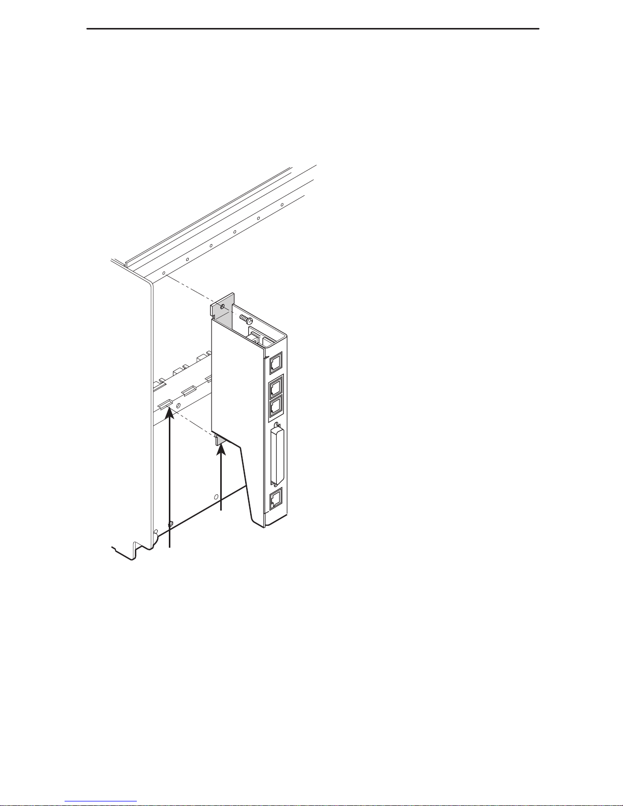
1. Install the rear connector module loosely onto the 3000 Series Carrier. Do not
tighten the screw.
98-16083
3000 Series
Carrier
Slots
Tabs
Rear
Connector
Module
NOTE:
If an auxiliary backplane for Models 3151 or 3161 DSUs is installed in the
same carrier, verify that it is mounted over slots 9–16. Slot 9 is rendered
inaccessible if the auxiliary backplane is mounted over slots 1–8.
Page 5
3
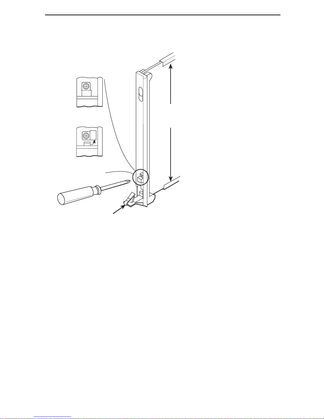
2. Insert the DSU/CSU circuit card into the appropriate slot in the carrier and lock the
latch.
Circuit
Card
Guides
Circuit
Pack
Lock
Latch
Open
(Unlocked)
Closed
(Locked)
495-14813
3. Tighten the screw on the rear connector module.
4. Attach a modular cable (not included) to the COM connector of the rear connector
module. (See the
User’s Guide
for detailed cable and connector information.)
Connect the other end to a terminal or PC.
5. Attach the DB25 port cable to the PORT 1 connector on the rear connector module.
Connect the other end of the cable to the customer premises equipment.
6. Attach the network cable to the Network connector on the rear connector module.
Connect the other end of the network cable to the connection provided by the
telephone company.
Page 6
4
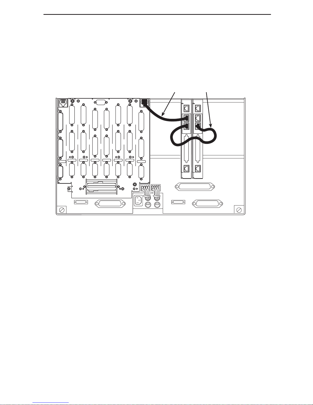
7. To daisy-chain the diagnostic channel with that of other 3166 DSU/CSUs or a T1
auxiliary backplane, insert one end of the short diagnostic channel extension cable
into either DIAGNOSTIC CHANNEL connector on the rear connector module.
Insert the other end into either DIAGNOSTIC CHANNEL connector of a
neighboring 3166 rear connector module, or the diagnostic channel connector of a
T1 auxiliary backplane.
98-16080
PORT
1
PORT1PORT
1
PORT1PORT
1
PORT
1
PORT
1
PORT
1
CLOCK IN
DIAGNOSTIC
CHAN
PORT
2
PORT2PORT
2
PORT
2
PORT
2
PORT2PORT
2
PORT
2
DTE
DTE DTE DTE DTE DTE DTE
DTE
SLT 8 (16)
SLOT 6 (14)
SLOT 7 (15)
SLOT 5 (13)
SLOT 4 (12) SLOT 3 (11)
SLOT 2 (10)
SLOT 1 (9)
T1 NETWORK
INTERFACE
COMCODE
107170409
MODEL NO.
3100-F1-900
DIAGNOSTIC
CHAN
CAUTION:
DISCONNECT ALL TELEPHONE LINES AT THE NETWORK
INTERFACE BEFORE TOUCHING OR SERVICING
Diagnostic Channel
Extension Cable
NET
PORT 1
COM
DIAGNOSTIC
CHANNEL
NET
PORT 1
COM
DIAGNOSTIC
CHANNEL
The power-up self-test begins when power is applied. During the power-up self-test, the
Fail LED flashes, then all LEDs blink twice. When the test is complete, verify that the
DSU/CSU is functional by observing that the OK and NET Sig LEDs are lit.
The Factory 1 configuration for ESF framing format and B8ZS line coding format is the
default configuration and is appropriate for most networks. If this configuration does not
work for you, try the Factory 2 configuration for D4 framing format and AMI line coding
format. To further customize configuration options, refer to
Changing Configuration
Options
in Chapter 3,
Operation
, and Appendix C,
Configuration Options
, in the
ACCULINK 3166 DSU/CSU User’s Guide
.
Page 7
5
Configuration Options
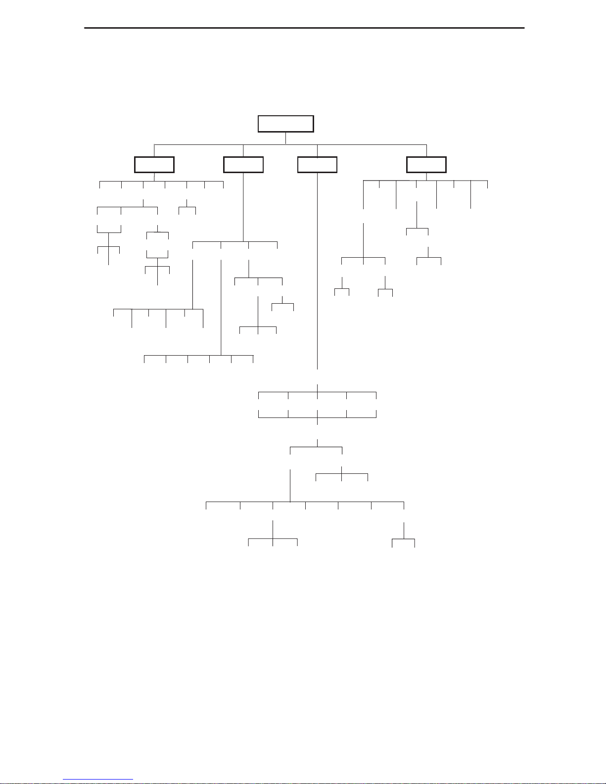
Configuration options are accessed from the Cnfig branch of the front panel menu.
DSU ESF
Stat
98-16084-01
DevHS
STest Perf TStat LED ID
T1 Prt1Prt1UserTelco
Cur
24Tot
Intvl
FarNear
Cur
8Tot
Intvl
Test
Rlpbk Lpbk Ptrns Lamp
QRSS 511
Abort Mon
LLBUP
LLBDN
54UP
54DN
FT1UP
FT1DN
PLB RLBLLBAbort DCLB DTLB
QRSS1in8 511
Send
Cnfig Ctrl
Rel
ClrReg
Reset
CID
Passwd
ACO
DL
Call
Load Edit Area From:
Choose Function:
Activ Cust1 Cust2 Fact1 Fact2
User AlarmNETPrt1 Chan Gen Mgmt
Gen Trap
Prt1ClearDsply
Save
Cust1Activ Cust2
Edit
User Prt1
FarNear
DiscDial ChDir
1 . . 5,A
(Directory)
1 . . 5,A
(Directory)
*
Available only if a device
failure has occured.
Clear
*
Page 8

6
Table 1. Port Configuration Options (1 of 2)
Option Factory 1 Factory 2 Comments/Description
E530 E530
V.35 V.35
p
p
-
Port Type:
RS449 RS449
Selects th
e port type:
EIA-530A
,
V .35, RS449, or X.21.
X.21 X.21
Nx64 Nx64
Enables the port to either Nx56 or
Base Rate:
Nx56 Nx56
Enables the ort to either Nx56 or
Nx64 rates.
Disab Disab
V .54 V.54
Network-initiated DCLB, allows
Net DCLB:
FT1 FT1
,
DCLB to be controlled by inband
V.54 or FT1 (ANSI) codes.
Both Both
()
Disab Disab
DTLB DTLB
Port-initiated Loopbacks, allows
Port LB:
DCLB DCLB
Loopbacks to be initiated through
the port by the external DTE.
Both Both
y
Disab Disab
DTR DTR
All ones sent to network (DTE) T1
All Ones:
RTS RTS
All ones sent to network (DTE) T1
when DTR or RTS interrupted.
Both Both
Rcv Yellow:
None None
Data port remains enabled, or is
Rcv Y ellow:
(Received Y ellow)
Halt Halt
disabled, on receiving Y ellow on
network T1.
Int Int
Selects whether the transmitted
Tx Clock:
Ext Ext
data clock is internal (TXC) or
external (XTXC).
InvertTxC:
Enab Enab
Selects phase inversion of the
InvertTxC:
(Invert Tx Clock)
Disab Disab
Selects hase inversion of the
transmit clock (TXC).
Enab Enab
Allows the data on the port to be
InvertData:
Disab Disab
Allows the data on the ort to be
inverted.
Enab Enab
Specifies whether the Embedded
EDL:
Disab Disab
S ecifies whether the Embedded
Data Link is enabled.
Page 9

7
Table 1. Port Configuration Options (2 of 2)
Option Comments/DescriptionFactory 2Factory 1
10E–4 10E–4
10E–5 10E–5
Err Rate:
10E–6 10E–6
Selects the error rate threshold for
(Excessive Error
Rate)
10E–7 10E–7
Excessive Error Rate Alarm.
)
10E–8 10E–8
10E–9 10E–9
Disab Disab
Maint Maint
Specifies whether the device will
Near-end:
Send Send
maintain near-end performance
statistics.
Both Both
Disab Disab
Specifies whether the device will
Far-end:
Maint Maint
maintain far-end performance
statistics.
Enab Enab
Specifies whether the EDL
Mgmt Link:
Disab Disab
S ecifies whether the EDL
Management Link is enabled.
Table 2. Network Interface Configuration Options (1 of 2)
Option Factory 1 Factory 2 Comments/Description
D4 D4
NET Framing:
ESF ESF
Selects D4 or ESF framing format.
AMI AMI
Selects AMI or B8ZS line coding
NET Coding:
B8ZS B8ZS
Selects AMI or B8ZS line coding
format.
0.0 0.0
–7.5 –7.5
LBO:
–15 –15
Provides Line Build Out in dB.
–22.5 –22.5
Enab Enab
Sends ANSI Performance Report
ANSI PRM:
Disab Disab
Sends ANSI Performance Re ort
Messages.
Enab Enab
Specifies whether the FDL’ s
Mgmt Link:
Disab Disab
S ecifies whether the FDLs
Management Link is enabled.
Page 10
8
Table 2. Network Interface Configuration Options (2 of 2)
Option Comments/DescriptionFactory 2Factory 1
Enab Enab
Network-initiated LLB allows LLB to
NET LLB:
Disab Disab
Network initiated LLB allows LLB to
be controlled by inband LLB codes.
Enab Enab Network-initiated PLB allows PLB
NET PLB:
Disab Disab
to be controlled by FDL PLB
messages.
6241 1
Provides enforcement of ones
BitStuff:
(Not
available
when Net Coding
Part68
density protection per AT&T TR
-
g
is B8ZS)
Disab
62411, ANSI T1-403
, and
FCC
Part 68 Technical Publication.
Circuit Ident:
Edit Edit
Specifies the transmission vendor’s
Circuit Ident:
Clear Clear
S ecifies the transmission vendor s
circuit identifier.
Table 3. General Configuration Options
Option Factory 1 Factory 2 Comments/Description
NET NET
Prt1 Prt1 Selects the clock source to be
Clock Src:
Int Int
used as the master clock for the
DSU/CSU.
Ext Ext
SU/CSU
Enab Enab
Specifies whether the durations of
TstTimout:
Disab Disab
user-initiated tests are limited by
Tst Duration.
10 10
Up Up
Specifies the duration of
TstD
uration:
Down Down
user-initiated loopback and pattern
tests.
Save Save
Page 11

9
Table 4. User Configuration Options (1 of 3)
Option Factory 1 Factory 2 Comments/Description
Enab Enab
Allows bypass of self-test on
Self-Test:
Disab Disab
Allows by ass of self-test on
initialization.
Enab Enab
Controls whether dial-in access is
Dial-In:
Disab Disab
Controls whether dial-in access is
allowed.
None None
Controls whether a password is
Password:
Com Com
Controls whether a assword is
required for remote access.
Enab Enab
Controls whether the COM port is
Com Port:
Disab Disab
Controls whether the COM ort is
enabled or disabled.
Mgmt Mgmt
Com Use:
ASCII ASCII
Controls how the COM port is
Term T erm
used
.
Disab Disab
ComExtDev:
AT AT
Specifies the type of external
Other Other
commands allowed
.
Edit Edit
Controls the COM port’s connect
ComConnPrefix:
Clear Clear
Controls the COM orts connect
prefix.
Edit Edit
Controls the COM port’s connect
ComConnected:
Clear Clear
Controls the COM orts connect
indication string.
p
Edit Edit
Controls the COM port’s escape
ComEscapeSeq:
Clear Clear
Controls the COM orts esca e
sequence.
None None
0.2s 0.2s
0.4s 0.4s
Controls the COM port’s escape
ComEscDel:
0.6s 0.6s
Controls the COM orts esca e
sequence delay.
0.8s 0.8s
1.0s 1.0s
Edit Edit
Controls the COM port’s
ComDisconnect:
Clear Clear
Controls the COM orts
disconnect string.
Page 12

10
Table 4. User Configuration Options (2 of 3)
Option Comments/DescriptionFactory 2Factory 1
1.2 1.2
2.4 2.4
Com Rate:
4.8 4.8
Selects the bit rate for the COM
(Communication Port
Rate)
9.6 9.6
Selects the bit rate for the COM
port.
ae)
14.4 14.4
19.2 19.2
7 7
Selects the character length for the
Char Length:
8 8
Selects the character length for the
COM port.
None None
CParity:
(Communication Port
Even Even
Selects the parity for the COM port.
(
Parity)
Odd Odd
p
1 1
CStop Bits:
(Communication Port
1.5 1.5
Selects the number of stop bits for
p
(
Stop Bits)
2 2
the COM port
.
Yes Yes
Specifies whether the COM port
Ignore DTR:
No No
S ecifies whether the COM ort
ignores DTR.
CmInActTm:
Enab Enab
Specifies whether the
(COM Port Inactivity
Timeout)
Disab Disab
communication port disconnects
after a certain period of inactivity.
5 5
CmDiscTm:
Up Up
Specifies the period of inactivity
(COM Port
Disconnect Time)
Down Down
(1 to 60 minutes) that causes a
disconnect if CmInActTm is
enabled.
Save Save
enabled
.
TnSession:
Enab Enab
Specifies whether the DSU/CSU
TnSession:
(Telnet Session)
Disab Disab
responds to Telnet session
requests.
TnPaswd:
Enab Enab
Specifies whether a password is
TnPaswd:
(Telnet Password)
Disab Disab
S ecifies whether a assword is
required for Telnet sessions.
Page 13

11
Table 4. User Configuration Options (3 of 3)
Option Comments/DescriptionFactory 2Factory 1
TnInActTm:
Enab Enab
Specifies whether a Telnet session
(Telnet Inactivity
Timeout)
Disab Disab
disconnects after a certain period
of inactivity.
5 5
TnDiscTm:
Up Up
The period of inactivity (1 to
(Telnet Disconnect
Time)
Down Down
60 minutes) that causes a
disconnect if TnInActTm is
enabled.
Save Save
enabled
.
Table 5. Alarm Configuration Options (1 of 2)
Option Factory 1 Factory 2 Comments/Description
Disab Disab Does not display alarm messages.
Alrm Msg:
Com Com
Sends alarm messages to COM
port.
Enab Enab
SNMP Trap:
Disab Disab
Sends SNMP traps.
Enab Enab
Specifies whether the modem
TrapDisc:
Disab Disab
connection will disconnect after a
trap is sent.
Enab Enab
Provides the option to allow
DialOut:
Disab Disab
automatic dial-out to send alarm
messages on the COM port.
Enab Enab
Specifies whether an outgoing call
Call Retry:
Disab Disab
is retried on a busy or failed call
attempt.
Dial Delay:
1–4
5
6–10
1–4
5
6–10
The time (in minutes) to delay
between successive alarm
dial-outs or retry attempts.
AltDialDir:
None
1–5
None
1–5
The alternate dial-out directory to
use if a call to the primary number
cannot be completed.
Page 14

12
Table 5. Alarm Configuration Options (2 of 2)
Option Comments/DescriptionFactory 2Factory 1
10E–4 10E–4
10E–5 10E–5
Err Rate:
10E–6 10E–6
The error rate threshold for
(Excessive Error
Rate)
10E–7 10E–7
Excessive Error Rate Alarm.
Rate)
10E–8 10E–8
10E–9 10E–9
AlrmRelay:
Enab Enab
Specifies whether to activate the
AlrmRelay:
(Alarm Relay)
Disab Disab
S ecifies whether to activate the
alarm relay on an alarm condition.
Table 6. General Management Configuration Options (1 of 2)
Option Factory 1 Factory 2 Comments/Description
Enab Enab
Specifies whether the DSU/CSU
SNMP Mgt:
Disab Disab
responds to SNMP session
requests.
Enab Enab
Specifies whether the DSU/CSU
validates the IP address of an
NMS Valid:
Disab Disab
validates the IP address of an
SNMP manager attempting
access.
1 1
The number of SNMP managers
Num Sec Mgrs:
2–10 2–10
The number of SNMP managers
allowed to access the DSU/CSU.
Edit Edit
Allows you to define or clear the
NMS n IP Adr:
Clear Clear
allowable IP address of an SNMP
manager .
Read Read
The type of access allowed for an
NMS n Acs:
R/W R/W
SNMP manager using community
name 1.
Edit Edit
The SNMP system name for this
System Name:
Clear Clear
The SNMP system name for this
device.
Edit Edit
The SNMP system location for this
System Location:
Clear Clear
The SNMP system location for this
device.
Page 15

13
Table 6. General Management Configuration Options (2 of 2)
Option Comments/DescriptionFactory 2Factory 1
Edit Edit
The SNMP system contact name
System Contact:
Clear Clear
The SNMP system contact name
for this device.
Edit Edit
A community name that is allowed
CommunityName1:
Clear Clear
access to this device. Defaults to
public
.
Read Read
The type of access allowed for
Access 1:
R/W R/W
The ty e of access allowed for
community name 1.
Edit Edit
A community name that is allowed
CommunityName2:
Clear Clear
A community name that is allowed
access to this device.
Read Read
The type of access allowed for
Access 2:
R/W R/W
The ty e of access allowed for
community name 2.
Edit Edit
The IP address for the COM port
Com IP Adr:
Clear Clear
The IP address for the COM ort
when configured for SNMP.
Edit Edit
The Subnet Mask needed to
Com NetMask:
Clear Clear
access the device when the COM
port is configured for SNMP.
PPP PPP
The link layer protocol for the COM
Com Link:
SLIP SLIP
The link layer rotocol for the COM
port when configured for SNMP.
Page 16

14
Table 7. Management Trap Configuration Options
Option Factory 1 Factory 2 Comments/Description
Num Trap Mgrs:
1
2–6
1
2–6
The number of trap managers
supported by the device.
Edit Edit
Specifies the IP address for each
trap mana
g
er. This configuration
Trapn IP Adr:
Clear Clear
tra manager. This configuration
option is repeated for all
n
managers.
None None
IPBus IPBus
Trapn Dst:
Com Com
Specifies the network destination
p
FDL FDL
for Trap Manager
n.
EDL1 EDL1
Disab Disab
Warm Warm Specifies the general trap types to
Gen Trap:
Auth Auth
enable: WarmStart, Authentication
Failure or both.
Both Both
aueobo
Enab Enab
Specifies whether the
Entp Trap:
Disab Disab
EnterpriseSpecific trap type is
enabled.
Disab Disab
Up Up Specifies the link trap type to
Link Trap:
Down Down
enable: Trap on Link Up, Link
Down, or both.
Both Both
o,obo
NET NET
Trap I/F:
Port Port
When any link trap types are
enabled, specifies which links to
Tra I/F:
Both Both
,
send traps for.
Page 17

15
Important Safety Instructions
1. Read and follow all warning notices and instructions marked on the product or
included in the manual.
2. Slots and openings in the cabinet are provided for ventilation. To ensure reliable
operation of the product and to protect it from overheating, these slots and
openings must not be blocked or covered.
3. Do not allow anything to rest on the power cord and do not locate the product
where persons will walk on the power cord.
4. Do not attempt to service this product yourself, as opening or removing covers may
expose you to dangerous high voltage points or other risks. Refer all servicing to
qualified service personnel.
5. General purpose cables are provided with this product. Special cables, which may
be required by the regulatory inspection authority for the installation site, are the
responsibility of the customer.
6. When installed in the final configuration, the product must comply with the
applicable Safety Standards and regulatory requirements of the country in which it
is installed. If necessary, consult with the appropriate regulatory agencies and
inspection authorities to ensure compliance.
7. A rare phenomenon can create a voltage potential between the earth grounds of
two or more buildings. If products installed in separate buildings are
interconnected, the voltage potential may cause a hazardous condition. Consult a
qualified electrical consultant to determine whether or not this phenomenon exists
and, if necessary, implement corrective action prior to interconnecting the products.
8. Input power to the ac voltage configuration of this product must be provided by a
UL-listed or CSA-certified power source with a Class 2 or Limited Power Source
(LPS) output. Input power to the dc voltage configurations of this product must be
provided by a National Electric Code (NEC) or a Canadian Electric Code (CEC)
Class 2 circuit.
9. This product contains a coin cell lithium battery that is only to be replaced at the
factory. Caution: There is a danger of explosion if the battery is incorrectly
replaced. Replace only with the same type. Dispose of used batteries according to
the battery manufacturer’s instructions. Attention: Il y a danger d’explosion s’il y a
remplacement incorrect de la batterie. Remplacer uniquement avec une batterie du
même type. Mettre au rebut les batteries usagées conformément aux instructions
du fabricant.
10. In addition, if the equipment is to be used with telecommunications circuits, take the
following precautions:
— Never install telephone wiring during a lightning storm.
— Never install telephone jacks in wet locations unless the jack is specifically
designed for wet locations.
— Never touch uninsulated telephone wires or terminals unless the telephone
line has been disconnected at the network interface.
— Use caution when installing or modifying telephone lines.
Page 18

16
— Avoid using a telephone (other than a cordless type) during an electrical storm.
There may be a remote risk of electric shock from lightning.
— Do not use the telephone to report a gas leak in the vicinity of the leak.
EMI Warnings
!
WARNING:
This equipment has been tested and found to comply with the limits for a
Class A digital device, pursuant to Part 15 of the FCC rules. These limits are
designed to provide reasonable protection against harmful interference when
the equipment is operated in a commercial environment. This equipment
generates, uses, and can radiate radio frequency energy and, if not installed
and used in accordance with the instruction manual, may cause harmful
interference to radio communications. Operation of this equipment in a
residential area is likely to cause harmful interference in which case the user
will be required to correct the interference at his own expense.
The authority to operate this equipment is conditioned by the requirements
that no modifications will be made to the equipment unless the changes or
modifications are expressly approved by Paradyne Corporation.
!
WARNING:
To Users of Digital Apparatus in Canada:
This Class A digital apparatus meets all requirements of the Canadian
interference-causing equipment regulations.
Cet appareil numérique de la classe A respecte toutes les exigences du
règlement sur le matérial brouilleur du Canada.
Government Requirements and Equipment Return
Certain governments require that instructions pertaining to CSU connection to the
telephone network be included in the installation and operation manual. Specific
instructions are listed in the following sections.
Notice to Users of the United States Telephone Network
1. This equipment complies with Part 68 of the FCC rules. On the equipment is a label
that contains, among other information, the FCC registration number for this
equipment. The label is on the 3166 DSU/CSU’s circuit card. If requested, this
information must be provided to the telephone company.
2. The T1 network connection should be made using a Universal Service Order Code
(USOC) type RJ48C jack. The Service Order Code 6.0F should be specified to the
telephone company when ordering the T1 line. In addition, the proper Facility
Interface Code must be specified to the Telephone Company. The DSU/CSU can
Page 19

17
be configured to support any of the following framing format and line signaling
techniques. The DSU/CSU’s configuration must correspond to the T1 line’s
parameters.
3166 DSU/CSU Facility Interface Codes
Code
Description
04DU9-BN 1.544 Mbps superframe format (SF) without line power
04DU9-DN 1.544 Mbps SF and B8ZS without line power
04DU9-1KN 1.544 Mbps ANSI ESF without line power
04DU-1SN 1.544 Mbps ANSI ESF and B8ZS without line power
3. If the 3166 DSU/CSU causes harm to the telephone network, the telephone
company will notify you in advance that temporary discontinuance of service may
be required. But if advance notice is not practical, the telephone company will notify
the customer as soon as possible. Also, you will be advised of your right to file a
complaint with the FCC if you believe it is necessary.
4. The telephone company may make changes in its facilities, equipment, operations,
or procedures that could affect the operation of the equipment. If this happens, the
telephone company will provide advance notice in order for you to make the
necessary modifications in order to maintain uninterrupted service.
5. If you experience trouble with this equipment, please contact your sales or service
representative (as appropriate) for repair or warranty information. If the product
needs to be returned to the company service center for repair, contact them directly
for return instructions using one of the following methods:
— Via the Internet: Visit the Paradyne World Wide Web site at
http://www.paradyne.com
— Via Telephone: Call our automated call system to receive current information
via fax or to speak with a company representative.
Within the U.S.A., call 1-800-870-2221
Outside the U.S.A., call 1-727-530-2340
If the trouble is causing harm to the telephone network, the telephone company
may request that you remove the equipment from the network until the problem is
resolved.
6. FCC compliant telephone line cords with modular plugs are provided with this
equipment. This equipment is designed to be connected to the telephone network
or premises wiring using a compatible modular jack which is Part 68 compliant.
Page 20

18
Notice to Users of the Canadian Telephone Network
The Industry Canada label identifies certified equipment. This certification means that
the equipment meets telecommunications network protective, operational and safety
requirements as prescribed in the appropriate Terminal Equipment Technical
Requirements document(s). The Department does not guarantee the equipment will
operate to the user’s satisfaction.
Before installing this equipment, users should ensure that it is permissible to be
connected to the facilities of the local telecommunications company. The equipment
must also be installed using an acceptable method of connection. The customer should
be aware that compliance with the above conditions may not prevent degradation of
service in some situations.
Repairs to certified equipment should be coordinated by a representative designated by
the supplier. Any repairs or alterations made by the user to this equipment, or
equipment malfunctions, may give the telecommunications company cause to request
to disconnect the equipment.
Users should ensure for their own protection that the electrical ground connections of
the power utility, telephone lines and internal metallic water pipe system, if present, are
connected together. This precaution may be particularly important in rural areas.
CAUTION:
Users should not attempt to make such connections themselves, but should
contact the appropriate electric inspection authority, or electrician, as
appropriate.
The Ringer Equivalence Number (REN) assigned to each terminal device provides an
indication of the maximum number of terminals allowed to be connected to a telephone
interface. The termination on an interface may consist of any combination of devices
subject only to the requirement that the sum of the Ringer Equivalence Numbers of all
the devices does not exceed 5.
If your equipment is in need of repair, refer to
Warranty, Sales, and Service Information
in the front of this document.
*3166–A2–GL11–10*
 Loading...