

Page 1

ACCULINK® DSU/CSU
Models 3160-A3, 3161-B3,
3164-A2, and 3165-A2
Operator’s Guide
Document No. 3160-A2-GB21-90
February 2001
Page 2

Copyright © 2001 Paradyne Corporation.
All rights reserved.
Printed in U.S.A.
Notice
This publication is protected by federal copyright law. No part of this publication may be copied or distributed,
transmitted, tr ansc ribed, store d in a re trie v al syst em, or tr ans lated into a n y huma n or com puter l anguag e in an y form or
by any means, electronic, mechanic al , ma gne tic, manual or otherwise, or dis cl os ed to third parties without th e express
written permission of Paradyne Corporation, 8545 126th Ave. N., Largo, FL 33773.
Paradyne Corporation makes no representation or warranties with respect to the contents hereof and specifically
disclaims any implied warranties of merchantability or fitness for a particular purpose. Further, Paradyne Corporation
reserves the right to revise this publication and to make changes from time to time in the contents hereof without
obligation of Paradyne Corporation to notify any person of such revision or changes.
Changes and enhancements to the product and to the information herein will be documented and issued as a new
release to this manual.
Standalone
FCC Registration number: See label on unit
Ringer Equivalence number (REN): See label o n unit
Canadian Certification number: See label on unit
Canadian DOC Load number: See label on unit
Carrier Card
FCC Registration number: See label on unit
Ringer Equivalence number (REN): See label o n unit
Canadian Certification number: See label on unit
Canadian DOC Load number: See label on unit
Warranty, Sales, Service, and Training Information
Contact your local sale s representativ e, se rvice representativ e, or distrib utor directly f or any hel p needed. F or additional
information concerning warranty, sales, service, repair, installation, documentation, training, distributor locations, or
Paradyne worldwide office locations, use one of the following methods:
Internet:
www.paradyne.com/warranty
Telephone:
representative.
— Within the U.S.A., call 1-800-870-2221
— Outside the U.S.A., call 1-727-530-2340
Visit the Paradyne World Wide Web s i te at
.)
Call our automated system to receive current information by fax or to speak with a company
www.paradyne.com
. (Be sure to register your warranty at
Document Feedback
We welcome your comments and suggestions about this document. Please mail them to Technical Publications,
Paradyne Corporation, 8545 126th Ave. N., Largo, FL 33773, or send e-mail to
number and title of this document in your correspondence. Please include your name and phone number if you are
willing to provide additional clarification.
userdoc@paradyne.com
. Include the
Trademarks
ACCULINK, COMSPHERE, FrameSaver, Hotwire, MVL, NextEDGE, OpenLane, and Performance Wizard are
registered trademarks of Paradyne Corporation. ReachDSL and TruePut are trademarks of Paradyne Corporation. All
other products and s ervices m en tion ed here in are the trademarks, service marks , registered trademarks, or regi ste red
service marks of their respective owners.
February 2001 3160-A2-GB21-90
A
Page 3

!
Importan t Safety Instructions
1. Read and follow all warning notices and instructions marked on the product or included in the manual.
2. This product (when not powered by the optional direct feed cable) is intended to be used with a 3-wire grounding
type plug – a plug which has a grounding pin. This is a safety feature. Equipment grounding is vital to ensure safe
operation. Do not defeat the purpose of the grounding type plug by modifying the plug or using an adapter.
Prior to installation , u se an o utl et tes ter or a voltmeter to check t he ac re cep tac le for the presence o f e arth ground .
If the receptacle is not properly grounded, the installation must not continue until a qualified electrician has
corrected the problem.
If a 3-wire grounding type power source is not available, consult a qualified electrician to determine another
method of grounding the equipment.
3. Slots and openings in the cabinet are provided for ventilation. To ensure reliable operation of the product and to
protect it from overheating, these slots and openings must not be blocked or covered.
4. Do not allow an ything to rest on th e pow er cord and d o not locat e the produc t where pe rsons will walk on the pow er
cord.
5. Do not attempt to service this product yourself, as opening or remo vi ng covers may expose you to dan gero us hi gh
voltage points or other risks. Refer all servicing to qualified service personnel.
6. General purpose cables are provided with this product. Special cables, which may be required by the regulatory
inspection authority for the installation site, are the responsibility of the customer.
7. When installed in the final configuration, the product must comply with the applicable Safety Standards and
regulatory requirements of the country in which it is installed. If necessary, consult with the appropriate regulatory
agencies and inspection authorities to ensure compliance.
8. A rare phenomenon ca n create a v oltag e potent ial betwee n the earth groun ds of two or more b uil dings . If pro ducts
installed in separate buildings are
Consult a qualified electrical consultant to determine whether or not this phenomenon exists and, if necessary,
implement corrective action prior to interconnecting the products.
9. This product contains a coin cell lithium battery that is only to be replaced at the factory.
danger of explosion if the battery is incorrectly replaced. Replace only with the same type. Dispose of used
batteries according to the battery manufacturer’s instructions.
remplacement incorrect de la batterie. Remplacer uniquement avec une batterie du même type. Mettre au rebut
les batteries usagées conformément aux instructions du fabricant.
10. In addition, if the equipment is to be used with telecommunications circuits, take the following precautions:
— Never install telephone wiring during a lightning storm.
— Never install telephone jacks in wet locations unless the jack is specifically designed for wet locations.
— Neve r tou ch uninsulated telephone wires or terminals unless the telephon e l ine has been disconnected at t he
network interface.
— Use caution when installing or modifying telephone lines.
— Av oid usi ng a tele pho ne (othe r than a co rdless type) du ring an el ectrical s torm. There ma y be a remo te risk of
electric shock from lightning.
— Do not use the telephone to report a gas leak in the vicinity of the leak.
interconnected
, the voltage potential may cause a hazardous condition.
There is a
Attention:
Caution:
Il y a danger d’explosion s’il y a
3160-A2-GB21-90 February 2001
B
Page 4

Direct Feed Power Supply Warning
!
WARNING:
When energizing this product with the supplied direct feed power cable, connect only to a SELV (Safety
Extra Low Voltage) power sourc e with a maximum available output of less than 240 VA. Power
configurations which utilize the direct feed cable to energize the equipment must only be installed by a
qualified electrician in restricted area access locations in accordance with articles 110-16, 110-17, and
110-18 of the National Electric Code (NEC), and articles 2-308, 2-310, 2-312, 2-314, 2-200, and 2-202 of the
Canadian Electric Code (CEC).
A readily accessible disconnect device as part of the building installation shall be incorporated in fixed
wiring. The disconnect devic e (a 24 or 48 Vdc, 15 or 20 A circuit breaker or s witc h) m ust be incl uded in the
ungrounded supply conductor. Over current protection must be a 24 or 48 Vdc, 15 or 20 A fuse or circuit
breaker.
EMI Notices
!
UNITED STATES – EMI NOTICE:
This equipment has been tested and found to comply with the limits for a Class A digital device, pursuant
to Part 15 of the FCC rules. These limits are designed to provide reasonable protection against harmful
interference when the equipment is operated in a commercial environment. This equipment generates,
uses, and can radiate radio frequency energy and, if not installed and used in accordance with the
instruction manual, ma y cause harmful interf erence to radio comm unications. Ope ration of this equipment
in a residential area is likely to cause harmful interference in which case the user will be required to
correct the interference at his own expense.
The authority to operate this equipment is conditioned by the requirements that no modifications will be
made to the equipment unless the changes or modifications are expressly approved by Paradyne
Corporation.
!
CANADA – EMI NOTICE:
This Class A digital apparatus meets all requirements of the Canadian interference-causing equipment
regulations.
Cet appareil numérique de la classe A respecte toutes les exigences du réglement sur le matérial
brouilleur du Canada.
February 2001 3160-A2-GB21-90
C
Page 5

Government Requirements and Equipment Return
Certain governments require that instructions pertaining to CSU and modem connection to the telephone network be
included in the installation and operation manual. Specific instructions are listed in the following sections.
United States
NOTICE TO USERS OF THE UNITED STATES TELEPHONE NETWORK
1. This equipment complies with Part 68 of the FCC rules. On the equipment is a label that contains, among other
information, the FCC registration number and ringer equivalence number (REN) for this equipment. The label is
located on the bottom of the stan dal on e 316 0, 3164, or 3165 DSU/CSU , and on the 3161 DSU/CSU’s circuit card.
If requested, this information must be provided to the telephone company.
2. There are two types of telephone lines associated with the standalone equipment. The T1 network connection
should be made using a Universal Service Order Code (USOC) type RJ48C jack. The Service Order Code 6.0F
should be specified to the telephone company when ordering the T1 line. In addition, the proper Facility Interface
Code must be specified to the Telephone Company. The DSU/CSU can be configured to support any of the
following framing format and line signaling techniques. The DSU/CSU’s configuration must correspond to the T1
line’s parameters. The standalone 3160, 3164, or 3165 DSU/CSU’s internal modem connects to the Public
Switched Telephone Network using a USOC Type RJ11C jack. The Facility Interface Code 02LS2 along with the
RJ11C jack should be specified to the telephone company when ordering a dial line for the modem. The
3161 DSU/CSU connects to the T1 network using the multi-line USOC-type RJ48H jack and does not have a
PSTN interface.
316x DSU/CSU Facility Interface Codes
Code Description
04DU9-BN 1.544 Mbps superframe format (SF) without line power
04DU9-DN 1.54 4 Mbps SF and B8ZS without line power
04DU9-1KN 1.544 Mbps ANSI ESF without line power
04DU-1SN 1.544 Mbps ANSI ESF and B8ZS without line power
3. The ringer equival ence nu mber (R EN) is used to determine the q uantity of de vi ces w hich may be connected to the
telephone line. Excessive RENs on the telephone line may result in the devices not ringing in response to an
incoming call. In most, but not all areas, the sum of the RENs should not exceed five (5.0). To be certain of the
number of devices that may be connected to the line, as determined by the total RENs, contact the telephone
company to determine th e maximum RENs for the calling area.
4. If the 316x DSU/CSU causes harm to the telephone network, the telephone company will notify you in advance
that temporary discontinuance of service may be required. But if advance notice is not practical, the telephone
company will n otify th e cust omer as soon a s poss ib le . Also, you will be advis ed of your ri ght to fil e a com plain t with
the FCC if you believe it is necessary.
5. The telephone com pany may make ch anges in its facilitie s , equipment, operations, o r pro ce dure s th at c ou ld a f fect
the operation of the e quipment. If this happe ns, the te lephone c ompan y will pro vide adv anc e notice in o rder f or you
to make the necessary modifications in order to maintain uninterrupted service.
3160-A2-GB21-90 February 2001
D
Page 6

6. If you experience trouble with this equipm ent, please contact your sales or service rep res enta t ive (as appropriate)
for repair or warranty information. If the product needs to be returned to the company service center for repair,
contact them directly for return instructions using one of the following methods:
—
Internet:
—
Telephone:
company representa tive.
Within the U.S.A., call 1-800-870-2221
Outside the U.S.A., call 1-727-530-2340
If the trouble is causing harm to the telephone network, the telephone company may request that you remove the
equipment from the network until the problem is resolved.
7. The equipment’s modem cannot be used on pub lic coin service pro vided by the telephone compan y. Connection to
Party Line Service is su bje ct to st ate t ariffs. (Conta ct the st ate pu bl ic uti lity comm ission, pub l ic se rvice commis sion
or corporation commission for information.)
8. FCC compliant telephone line cords with modular plugs are provided with this equipment. This equipment is
designed to be connected to the telephone network or premises wiring using a compatible modular jack which is
Part 68 compliant.
Visit the Paradyne World Wide Web site at http://www.paradyne.com
Call our automated response system to receive current information via fax or to speak with a
Canada
NOTICE TO USERS OF THE CANADIAN TELEPHONE NETWORK
The Canadian Department of Communications label identifies certified equipment. This certification means that the
equipment meets certain telecommunications network protective, operational and safety requirements. The
Department does not guarantee the equipment will operate to the user’s satisfaction.
Before installing this equipment, users should ensure that it is permissible to be connected to the facilities of the local
telecommunications company. The equipment must also be installed using an acceptable method of connection. In
some cases, the company’s inside wi ring ass oc ia t ed with a single line individual se rvice may be extende d by means of
a certified connector assembly (telephone extension cord). The customer should be aware that compliance with the
above conditions may not prevent degradation of service in some situations.
Repairs to certified equipment should be made by an authorized Canadian maintenance facility designated by the
supplier. Any repairs or alterations made by the user to this equipment, or equipment malfunctions, may give the
telecommunications company cause to request to disconnect the equipment.
CAUTION:
Users should not attempt to make such connections themselves, but should contact the appropriate
electric inspection authority, or electrician, as appropriate.
If your equipment is in need of repair, return it using the procedures described on page A in the front of this document.
February 2001 3160-A2-GB21-90
E
Page 7

Contents
About This Guide
1 Introduction
Document Purpose and Intended Audience . . . . . . . . . . . . . . . . . . . . vii
Document Summary . . . . . . . . . . . . . . . . . . . . . . . . . . . . . . . . . . . . . . vii
Product-Related Documents . . . . . . . . . . . . . . . . . . . . . . . . . . . . . . . . viii
Reference Documents . . . . . . . . . . . . . . . . . . . . . . . . . . . . . . . . . . . . . ix
Overview . . . . . . . . . . . . . . . . . . . . . . . . . . . . . . . . . . . . . . . . . . . . . . . 1-1
Features. . . . . . . . . . . . . . . . . . . . . . . . . . . . . . . . . . . . . . . . . . . . . . . . 1-1
DTE Drop/Insert (DSX-1) Interface . . . . . . . . . . . . . . . . . . . . . . . . 1-2
Alarm Message Capability. . . . . . . . . . . . . . . . . . . . . . . . . . . . . . . 1-2
Front Panel Emulation . . . . . . . . . . . . . . . . . . . . . . . . . . . . . . . . . . 1-2
Integral Modem . . . . . . . . . . . . . . . . . . . . . . . . . . . . . . . . . . . . . . . 1-2
Async Terminal Interface Support . . . . . . . . . . . . . . . . . . . . . . . . . 1-2
Telnet Access . . . . . . . . . . . . . . . . . . . . . . . . . . . . . . . . . . . . . . . . 1-2
SNMP Management Support. . . . . . . . . . . . . . . . . . . . . . . . . . . . . 1-3
Physical Description. . . . . . . . . . . . . . . . . . . . . . . . . . . . . . . . . . . . . . . 1-3
Standalone DSU/CSU Front Panel . . . . . . . . . . . . . . . . . . . . . . . . 1-3
Standalone DSU/CSU Rear Panel . . . . . . . . . . . . . . . . . . . . . . . . 1-5
2 Installation
Overview . . . . . . . . . . . . . . . . . . . . . . . . . . . . . . . . . . . . . . . . . . . . . . . 2-1
Application Examples. . . . . . . . . . . . . . . . . . . . . . . . . . . . . . . . . . . . . . 2-1
SNMP or Telnet Connection Examples . . . . . . . . . . . . . . . . . . . . . . . . 2-3
Important Instructions. . . . . . . . . . . . . . . . . . . . . . . . . . . . . . . . . . . . . . 2-5
Optional Power Sources . . . . . . . . . . . . . . . . . . . . . . . . . . . . . . . . . . . 2-5
Installing the +24 Vdc Power Supply. . . . . . . . . . . . . . . . . . . . . . . 2-5
Installing the Single –48 Vdc Power Supply . . . . . . . . . . . . . . . . . 2-6
Installing the Redundant –48 Vdc Power Supply . . . . . . . . . . . . . 2-7
Cabling Examples . . . . . . . . . . . . . . . . . . . . . . . . . . . . . . . . . . . . . . . . 2-8
Power-Up Self-Test . . . . . . . . . . . . . . . . . . . . . . . . . . . . . . . . . . . . . . . 2-9
3160-A2-GB21-90 February 2001
i
Page 8

Contents
3 Operation
Overview . . . . . . . . . . . . . . . . . . . . . . . . . . . . . . . . . . . . . . . . . . . . . . . 3-1
Using the Front Panel . . . . . . . . . . . . . . . . . . . . . . . . . . . . . . . . . . . . . 3-1
LCD . . . . . . . . . . . . . . . . . . . . . . . . . . . . . . . . . . . . . . . . . . . . . . . . 3-2
Keypad. . . . . . . . . . . . . . . . . . . . . . . . . . . . . . . . . . . . . . . . . . . . . . 3-3
Test Jacks . . . . . . . . . . . . . . . . . . . . . . . . . . . . . . . . . . . . . . . . . . . 3-4
LEDs . . . . . . . . . . . . . . . . . . . . . . . . . . . . . . . . . . . . . . . . . . . . . . . 3-5
Displaying Unit Identity. . . . . . . . . . . . . . . . . . . . . . . . . . . . . . . . . . . . . 3-9
Setting Customer Identification . . . . . . . . . . . . . . . . . . . . . . . . . . . . . . 3-11
Selecting the DTE Drop/Insert or Data Port for LED Display. . . . . . . . 3-12
Displaying LED Conditions. . . . . . . . . . . . . . . . . . . . . . . . . . . . . . . . . . 3-13
Changing Configuration Options . . . . . . . . . . . . . . . . . . . . . . . . . . . . . 3-14
Displaying/Editing Configuration Options . . . . . . . . . . . . . . . . . . . 3-16
Saving Edit Changes . . . . . . . . . . . . . . . . . . . . . . . . . . . . . . . . . . . 3-17
Selecting/Copying to a Specific Port . . . . . . . . . . . . . . . . . . . . . . . 3-18
Configuring the DSU/CSU for SNMP or Telnet Access . . . . . . . . . . . . 3-19
Selecting the Port . . . . . . . . . . . . . . . . . . . . . . . . . . . . . . . . . . . . . 3-20
Setting the IP Address. . . . . . . . . . . . . . . . . . . . . . . . . . . . . . . . . . 3-21
Selecting the Link Layer Protocol . . . . . . . . . . . . . . . . . . . . . . . . . 3-23
Specifying the Community Name(s) and Access Type(s) . . . . . . . 3-24
Configuring SNMP Traps. . . . . . . . . . . . . . . . . . . . . . . . . . . . . . . . . . . 3-26
Enabling SNMP Trap Messages . . . . . . . . . . . . . . . . . . . . . . . . . . 3-26
Selecting the Number of Trap Managers. . . . . . . . . . . . . . . . . . . . 3-27
Configuring a Destination for SNMP Traps . . . . . . . . . . . . . . . . . . 3-28
Configuring DS0 Channels. . . . . . . . . . . . . . . . . . . . . . . . . . . . . . . . . . 3-29
Displaying DS0 Channel Assignments . . . . . . . . . . . . . . . . . . . . . 3-36
Allocating Data Ports . . . . . . . . . . . . . . . . . . . . . . . . . . . . . . . . . . . 3-38
Block or ACAMI Assignment Method. . . . . . . . . . . . . . . . . . . . . . . 3-40
Individual Channel Assignment Method . . . . . . . . . . . . . . . . . . . . 3-41
Allocating DS0 Channels from the DTE Drop/Insert Interface
to the Network Interface. . . . . . . . . . . . . . . . . . . . . . . . . . . . . . . . . 3-42
Clearing DS0 Channel Allocation . . . . . . . . . . . . . . . . . . . . . . . . . 3-44
Providing Backup Capability . . . . . . . . . . . . . . . . . . . . . . . . . . . . . . . . 3-45
Selecting the Timing Source . . . . . . . . . . . . . . . . . . . . . . . . . . . . . . . . 3-45
Configuring for Network Timing. . . . . . . . . . . . . . . . . . . . . . . . . . . 3-47
Configuring for External Timing. . . . . . . . . . . . . . . . . . . . . . . . . . . 3-47
Establishing Access Security on a Port . . . . . . . . . . . . . . . . . . . . . . . . 3-48
Setting a Password . . . . . . . . . . . . . . . . . . . . . . . . . . . . . . . . . . . . . . . 3-49
Entering a Password to Gain Access. . . . . . . . . . . . . . . . . . . . . . . . . . 3-50
February 2001 3160-A2-GB21-90
ii
Page 9

Acquiring/Releasing the User Interface . . . . . . . . . . . . . . . . . . . . . . . . 3-51
Acquiring the Active User Interface . . . . . . . . . . . . . . . . . . . . . . . . 3-52
Releasing the Active User Interface . . . . . . . . . . . . . . . . . . . . . . . 3-53
Enabling/Disabling the Front Panel . . . . . . . . . . . . . . . . . . . . . . . . . . . 3-54
Using the Integral Modem in Standalone DSU/CSUs . . . . . . . . . . . . . 3-55
Entering Numbers in the Phone Directories . . . . . . . . . . . . . . . . . 3-55
Initiating a Call for Front Panel Pass-Through Operation . . . . . . . 3-57
Initiating a Call for PC, ASCII Terminal/Printer, or
SNMP Operation . . . . . . . . . . . . . . . . . . . . . . . . . . . . . . . . . . . . . . 3-59
Disconnecting the Modem Connection . . . . . . . . . . . . . . . . . . . . . 3-60
Enabling the Communication Port for Carrier-Mounted DSU/CSUs . . 3-61
Deactivating the Alarm Relay for Carrier-Mounted DSU/CSUs . . . . . . 3-64
Resetting the DSU/CSU. . . . . . . . . . . . . . . . . . . . . . . . . . . . . . . . . . . . 3-65
Download Operations. . . . . . . . . . . . . . . . . . . . . . . . . . . . . . . . . . . . . . 3-65
User Interface Access Security for Standalone DSU/CSUs. . . . . . . . . 3-67
Changing User Interface Access Security . . . . . . . . . . . . . . . . . . . 3-68
Contents
4 Maintenance
Overview . . . . . . . . . . . . . . . . . . . . . . . . . . . . . . . . . . . . . . . . . . . . . . . 4-1
Self-Test Health . . . . . . . . . . . . . . . . . . . . . . . . . . . . . . . . . . . . . . . . . . 4-1
Device Health and Status. . . . . . . . . . . . . . . . . . . . . . . . . . . . . . . . . . . 4-3
Performance Reports. . . . . . . . . . . . . . . . . . . . . . . . . . . . . . . . . . . . . . 4-5
Alarms . . . . . . . . . . . . . . . . . . . . . . . . . . . . . . . . . . . . . . . . . . . . . . . . . 4-11
SNMP Traps. . . . . . . . . . . . . . . . . . . . . . . . . . . . . . . . . . . . . . . . . . . . . 4-12
Troubleshooting . . . . . . . . . . . . . . . . . . . . . . . . . . . . . . . . . . . . . . . . . . 4-14
Test Jacks . . . . . . . . . . . . . . . . . . . . . . . . . . . . . . . . . . . . . . . . . . . . . . 4-17
Test Commands. . . . . . . . . . . . . . . . . . . . . . . . . . . . . . . . . . . . . . . . . . 4-19
Remote Loopback Tests . . . . . . . . . . . . . . . . . . . . . . . . . . . . . . . . . . . 4-19
Sending a Line Loopback Up or Down . . . . . . . . . . . . . . . . . . . . . 4-20
Sending a V.54/ANSI FT1 Activation/Deactivation . . . . . . . . . . . . 4-21
Local Loopback Tests . . . . . . . . . . . . . . . . . . . . . . . . . . . . . . . . . . . . . 4-22
Starting a Line Loopback. . . . . . . . . . . . . . . . . . . . . . . . . . . . . . . . 4-23
Starting a Payload Loopback. . . . . . . . . . . . . . . . . . . . . . . . . . . . . 4-24
Starting a DTE Loopback. . . . . . . . . . . . . . . . . . . . . . . . . . . . . . . . 4-25
Starting a Repeater Loopback. . . . . . . . . . . . . . . . . . . . . . . . . . . . 4-26
Starting a Data Channel Loopback . . . . . . . . . . . . . . . . . . . . . . . . 4-27
Starting a Data Terminal Loopback . . . . . . . . . . . . . . . . . . . . . . . . 4-28
Aborting Loopbacks. . . . . . . . . . . . . . . . . . . . . . . . . . . . . . . . . . . . 4-29
Test Patterns . . . . . . . . . . . . . . . . . . . . . . . . . . . . . . . . . . . . . . . . . . . . 4-30
Sending Test Patterns . . . . . . . . . . . . . . . . . . . . . . . . . . . . . . . . . . 4-31
3160-A2-GB21-90 February 2001
iii
Page 10

Contents
Monitoring Test Patterns . . . . . . . . . . . . . . . . . . . . . . . . . . . . . . . . 4-33
Aborting Test Patterns. . . . . . . . . . . . . . . . . . . . . . . . . . . . . . . . . . 4-34
Lamp Test . . . . . . . . . . . . . . . . . . . . . . . . . . . . . . . . . . . . . . . . . . . . . . 4-35
Starting a Lamp Test . . . . . . . . . . . . . . . . . . . . . . . . . . . . . . . . . . . 4-35
Aborting a Lamp Test . . . . . . . . . . . . . . . . . . . . . . . . . . . . . . . . . . 4-36
Displaying DSU/CSU Test Status . . . . . . . . . . . . . . . . . . . . . . . . . . . . 4-37
A Front Panel Menu
B Technical Specifications
Overview . . . . . . . . . . . . . . . . . . . . . . . . . . . . . . . . . . . . . . . . . . . . . . . B-1
C Configuration Options
Overview . . . . . . . . . . . . . . . . . . . . . . . . . . . . . . . . . . . . . . . . . . . . . . . C-1
DTE Interface Configuration Options . . . . . . . . . . . . . . . . . . . . . . . . . . C-2
Port Configuration Options. . . . . . . . . . . . . . . . . . . . . . . . . . . . . . . . . . C-3
Network Interface Configuration Options . . . . . . . . . . . . . . . . . . . . . . . C-8
Channel Configuration Options . . . . . . . . . . . . . . . . . . . . . . . . . . . . . . C-10
General Configuration Options. . . . . . . . . . . . . . . . . . . . . . . . . . . . . . . C-16
User Interface Configuration Options. . . . . . . . . . . . . . . . . . . . . . . . . . C-18
Alarm Configuration Options . . . . . . . . . . . . . . . . . . . . . . . . . . . . . . . . C-28
Management Configuration Options . . . . . . . . . . . . . . . . . . . . . . . . . . C-32
Configuration Worksheets . . . . . . . . . . . . . . . . . . . . . . . . . . . . . . . . . . C-42
D Pin Assignments
Overview . . . . . . . . . . . . . . . . . . . . . . . . . . . . . . . . . . . . . . . . . . . . . . . D-1
T1 Network Interface . . . . . . . . . . . . . . . . . . . . . . . . . . . . . . . . . . . . . . D-1
DTE Drop/Insert Interface . . . . . . . . . . . . . . . . . . . . . . . . . . . . . . . . . . D-3
MODEM Port Interface. . . . . . . . . . . . . . . . . . . . . . . . . . . . . . . . . . . . . D-4
AUX Port Interface . . . . . . . . . . . . . . . . . . . . . . . . . . . . . . . . . . . . . . . . D-5
COM Port Interface . . . . . . . . . . . . . . . . . . . . . . . . . . . . . . . . . . . . . . . D-6
EIA-530-A Port Interface Connector . . . . . . . . . . . . . . . . . . . . . . . . . . D-8
EIA-530-A-to-RS-449 Cable Interface . . . . . . . . . . . . . . . . . . . . . . . . . D-9
EIA-530-A-to-V.35 Cable Interface . . . . . . . . . . . . . . . . . . . . . . . . . . . D-11
EIA-530-A-to-X.21 Cable Interface . . . . . . . . . . . . . . . . . . . . . . . . . . . D-13
Serial Crossover Cable . . . . . . . . . . . . . . . . . . . . . . . . . . . . . . . . . . . . D-14
Power Input Connector . . . . . . . . . . . . . . . . . . . . . . . . . . . . . . . . . . . . D-15
Optional DC Power Cable . . . . . . . . . . . . . . . . . . . . . . . . . . . . . . . . . . D-15
External Clock Interface. . . . . . . . . . . . . . . . . . . . . . . . . . . . . . . . . . . . D-16
February 2001 3160-A2-GB21-90
iv
Page 11

E SNMP MIB Objects
Overview . . . . . . . . . . . . . . . . . . . . . . . . . . . . . . . . . . . . . . . . . . . . . . . E-1
MIB II (RFC 1213) . . . . . . . . . . . . . . . . . . . . . . . . . . . . . . . . . . . . . . . . E-2
System Group, MIB II . . . . . . . . . . . . . . . . . . . . . . . . . . . . . . . . . . E-3
Interface Group, MIB II . . . . . . . . . . . . . . . . . . . . . . . . . . . . . . . . . E-4
IP Group, MIB II. . . . . . . . . . . . . . . . . . . . . . . . . . . . . . . . . . . . . . . E-10
ICMP Group, MIB II . . . . . . . . . . . . . . . . . . . . . . . . . . . . . . . . . . . . E-13
TCP Group, MIB II . . . . . . . . . . . . . . . . . . . . . . . . . . . . . . . . . . . . . E-13
UDP Group, MIB II. . . . . . . . . . . . . . . . . . . . . . . . . . . . . . . . . . . . . E-13
Transmission Group, MIB II. . . . . . . . . . . . . . . . . . . . . . . . . . . . . . E-13
SNMP Group, MIB II . . . . . . . . . . . . . . . . . . . . . . . . . . . . . . . . . . . E-14
DS1/E1 MIB (RFC 1406) . . . . . . . . . . . . . . . . . . . . . . . . . . . . . . . . . . . E-14
Near End Group, DS1/E1 MIB. . . . . . . . . . . . . . . . . . . . . . . . . . . . E-14
Far End Group, DS1/E1 MIB . . . . . . . . . . . . . . . . . . . . . . . . . . . . . E-18
DS1 Fractional Group, DS1/E1 MIB . . . . . . . . . . . . . . . . . . . . . . . E-19
RS-232-like MIB (RFC 1317) . . . . . . . . . . . . . . . . . . . . . . . . . . . . . . . . E-19
General Port Table, RS-232-like MIB . . . . . . . . . . . . . . . . . . . . . . E-20
Asynchronous Port Table, RS-232-like MIB . . . . . . . . . . . . . . . . . E-22
Synchronous Port Table, RS-232-like MIB . . . . . . . . . . . . . . . . . . E-23
Input Signal Table, RS-232-like MIB . . . . . . . . . . . . . . . . . . . . . . . E-23
Output Signal Table, RS-232-like MIB. . . . . . . . . . . . . . . . . . . . . . E-24
Generic-Interface MIB Extensions (RFC 1229) . . . . . . . . . . . . . . . . . . E-24
Generic Interface Test Table, Generic Interface MIB . . . . . . . . . . E-25
Enterprise MIB . . . . . . . . . . . . . . . . . . . . . . . . . . . . . . . . . . . . . . . . . . . E-27
Correlation between Menu Commands and SNMP Objects . . . . . . . . E-28
Contents
F IP Network Addressing Scenarios
Overview . . . . . . . . . . . . . . . . . . . . . . . . . . . . . . . . . . . . . . . . . . . . . . . F-1
Scenario 1 . . . . . . . . . . . . . . . . . . . . . . . . . . . . . . . . . . . . . . . . . . . . . . F-2
Scenario 2 . . . . . . . . . . . . . . . . . . . . . . . . . . . . . . . . . . . . . . . . . . . . . . F-3
Scenario 3 . . . . . . . . . . . . . . . . . . . . . . . . . . . . . . . . . . . . . . . . . . . . . . F-4
Scenario 4 . . . . . . . . . . . . . . . . . . . . . . . . . . . . . . . . . . . . . . . . . . . . . . F-5
Scenario 5 . . . . . . . . . . . . . . . . . . . . . . . . . . . . . . . . . . . . . . . . . . . . . . F-6
G Front Panel Emulation
Overview . . . . . . . . . . . . . . . . . . . . . . . . . . . . . . . . . . . . . . . . . . . . . . . G-1
Installing Front Panel Emulation Software . . . . . . . . . . . . . . . . . . . . . . G-1
Starting Front Panel Emulation . . . . . . . . . . . . . . . . . . . . . . . . . . . . . . G-3
3160-A2-GB21-90 February 2001
v
Page 12

Contents
H Asynchronous Terminal Operation
Overview . . . . . . . . . . . . . . . . . . . . . . . . . . . . . . . . . . . . . . . . . . . . . . . H-1
Before Using the Asynchronous Terminal . . . . . . . . . . . . . . . . . . . . . . H-1
Initiating an Asynchronous Terminal Session . . . . . . . . . . . . . . . . . . . H-2
Ending an Asynchronous Terminal Session . . . . . . . . . . . . . . . . . . . . H-3
Menu Organization. . . . . . . . . . . . . . . . . . . . . . . . . . . . . . . . . . . . . . . . H-4
Using Asynchronous Terminal Screens. . . . . . . . . . . . . . . . . . . . . . . . H-5
Setting Customer Identification . . . . . . . . . . . . . . . . . . . . . . . . . . . . . . H-7
Displaying LED Conditions. . . . . . . . . . . . . . . . . . . . . . . . . . . . . . . . . . H-8
Changing Configuration Options . . . . . . . . . . . . . . . . . . . . . . . . . . . . . H-9
Displaying or Editing Configuration Options . . . . . . . . . . . . . . . . . H-9
Saving Edit Changes . . . . . . . . . . . . . . . . . . . . . . . . . . . . . . . . . . . H-11
Establishing Access Security on a Port . . . . . . . . . . . . . . . . . . . . . . . . H-12
Setting a Password . . . . . . . . . . . . . . . . . . . . . . . . . . . . . . . . . . . . . . . H-13
Entering a Password to Gain Access. . . . . . . . . . . . . . . . . . . . . . . . . . H-14
Configuration Worksheets for the Asynchronous Terminal Interface. . H-15
I Equipment List
Glossary
Index
February 2001 3160-A2-GB21-90
vi
Page 13

About This Guide
Document Purpose and Intended Audience
This operator’s guide contains installation, operation, and maintenance information
for the ACCULINK 3160, 3161, 3164, or 3165 Data Service Unit (DSU)/Channel
Service Unit (CSU).
It is designed for installers and users of DSU/CSUs familiar with the operation of
digital data communication equipment.
Document Summary
Section Description
Chapter 1,
Chapter 2,
Chapter 3,
Chapter 4,
Appendix A,
Menu
Appendix B,
Specifications
Appendix C,
Options
Appendix D,
Appendix E,
Objects
Introduction
Installation
Operation
Maintenance
Front Panel
Technical
Configuration
Pin Assignments
SNMP MIB
Describes the 316x DSU/CSUs and their features.
Describes how to install the standalone units and make
connections. (Instructions for the carrier-mounted 3161
DSU/CSU are cont ained in the
3161 DSU/CSU General Information Guide
No. 3100-A2-GK40.)
Provides instructions for using the front panel, changing
configuration options, establishing security, and using the
internal modem.
Contains procedures for monitoring, testing, and
troubleshooting.
Contains a menu tree showing all the main front panel
functions.
Contains technical spec ifi ca tions for the 316x DSU/CSUs .
Contains all the co nfiguration options and default settings.
Shows the pin assignments for connectors and cables.
Describes the MIB objects supported by the DSU/CSUs.
ACCULINK 3151 CSU and
, Document
3160-A2-GB21-90 February 2001
vii
Page 14

About This Guide
Section Description
Appendix F,
Addressing Scenarios
Appendix G,
Emulation
Appendix H,
Terminal Operation
Appendix I,
Glossary
Index
IP Network
Front Panel
Asynchronous
Equipment List
Product-Related Documents
Document Number Document Title
3000-A2-GA31
3000-A2-GB41
Provides sample IP addressing schemes.
Explains how to use front panel em ula tion so ftwar e in l ieu
of the front panel.
Explains how to use a VT100-compatible terminal to
configure and control the unit.
Contains order numbers for cables and other related
parts.
Defines abbreviations and terms used in this document.
Lists key terms, concepts, and sections in alphabetical
order.
COMSPHERE 3000 Series Carrier Installation
Manual
COMSPHERE –48 VDC Central Office Power Unit
Installation Guide
3100-A2-GK40
ACCULINK 3151 CSU and 3161 DSU/CSU General
Information Guide
3162-A2-GB20
3163-A2-GB20
3166-A2-GB20
ACCULINK 3162 DSU/CSU User’s Guide
ACCULINK 3163 DSU/CSU User’s Guide
ACCULINK 3166 DSU/CSU User’s Guide
Contact your sales or service representative to order additional product
documentation.
Paradyne documents are also available on the World Wide Web at
www.paradyne.com
. Select
Library → Technical Manuals.
February 2001 3160-A2-GB21-90
viii
Page 15

Reference Documents
AT&T Technical Reference 54016
AT&T Technical Reference 62411
ANSI T1.403-1989
Industry Canada CS-03
CSA-22.2 No. 950
Industry Canada (ICES)-003
FCC Part 15
FCC Part 68
UL 1950
Management Information Base for Network Management of TCP/IP-Based
Internets:
Definitions of Managed Objects for the DS1 and E1 Interface Types
RFC 1406, January 1993
MIBII
. RFC 1213, March 1991
About This Guide
.
Definitions of Managed Objects for RS-232-like Hardware Devices
RFC 1317, April 1992
Extensions to the Generic-Interface MIB
. RFC 1229, May 1991
.
3160-A2-GB21-90 February 2001
ix
Page 16

About This Guide
February 2001 3160-A2-GB21-90
x
Page 17

Introduction
Overview
1
®
The ACCULINK
network and the customer premises equipment, converting signals received from
the DTE (Data T erminal Equipment) to bipolar signals that can be transmitted over
T1 lines. Typical applications include shared access to network-based services,
Local Area Network (LAN)/Wide Area Network (WAN) interconnection, and
fractional T1 network applications.
In addition to the T1 network interface and the DTE Drop/Insert (DSX-1) interface,
the Model 3160 provides two synchronous data ports while the Model 3164
provides four synchronous data ports. The Model 3165 provides one synchronous
data port, but does not provide the DTE Drop/Insert (DSX-1) interface.
316x DSU/CSU acts as an interface between the T1 digital
Features
The Model 3161 (carrier-mounted DSU/CSU) provides two ports in addition to the
DTE Drop/Insert (DSX-1) interface and is designed to fit into the COMSPHERE
3000 Series Carrier.
For more information about the carrier-mounted DSU/CSU, refer to the
3151 CSU and 3161 DSU/CSU General Information Guide
3000 Series Carrier Installation Manual
The DSU/CSU optimizes network performance with a wide range of features such
as the following:
Software configuration menu displayed via a liquid crystal display (LCD) to
permit quick and easy operation, and elimination of complicated hardware
strapping.
Local or remote configuration and operation flexibility.
Several loopback capabilities and test pattern generators.
DTE Drop/Insert (DSX-1) capability.
Alarm message disp lay/pr in t capab il ity.
Front panel emulation via Windows-based Front Panel Emulation software.
.
and the
ACCULINK
COMSPHERE
Integral modem for standalone DSU/CSUs.
3160-A2-GB21-90 February 2001
1-1
Page 18

1. Introduction
Asynchronous (async) terminal interface support.
Telnet access for remote async terminal operations.
Network management provided through industry-standard Simple Network
Management Protocol (SNMP).
DTE Drop/Insert (DSX-1) Interface
The DTE Drop/Insert interface allows DTEs/PBXs that support the DS1 signal
format to share the T1 network with other high-speed equipment. This is available
on 2-port and 4-port DSU/CSUs.
Alarm Message Capability
The DSU/CSU can be attached, either locally or remotely, to an ASCII terminal or
printer to display or print alarm messages. Alarms can also be displayed on a PC
that is using a terminal emulation package.
Front Panel Emulation
The DSU/CSU offers functionality through Front Panel Emulation software that is
similar to that provided by the DSU/CSU front panel. The functionality of the front
panel is available by clicking on the function keys with the mouse rather than by
pressing keys from the actual front panel.
Integral Modem
The standalone DSU/CSUs contain an integral low-speed (2400 bps), V .22bis dial
modem that enables communication with remote devices such as another
316x DSU/CSU, an ASCII terminal or printer, or a PC running the 3100 Series
Front Panel Emulation software.
Async Terminal Interface Support
The DSU/CSU can be configured and managed from an asynchronous (async)
terminal. The async terminal’s full screen display uses a menu hierarchy similar to
the DSU/CSU’s front panel. You can perform device management and
configuration operations as if you are using the DSU/CSU’s front panel, but you do
not have the limitation of the 2-line, 16-character LCD.
Telnet Access
Remote async terminal operations can be performed using T elnet access. T elnet is
a Transmission Control Protocol/Internet Protocol (TCP/IP) service that supports a
virtual terminal interface.
February 2001 3160-A2-GB21-90
1-2
Page 19

SNMP Management Support
SNMP is a network management protocol that is used to monitor network
performance and status, and to report alarms (i.e., traps). To function, SNMP
requires a manager consisting of a software program housed within a workstation
or PC; an agent consisting of a software program housed within a device (e.g., the
DSU/CSU); and a Management Information Base (MIB) consisting of a database
of managed objects. The DSU/CSU can be managed by any industry-standard
SNMP manager.
Two link layer protocols, Point-to-Point Protocol (PPP) and Serial Line Internet
Protocol (SLIP), are supported for connection to an external SNMP manager or
network device (e.g., a router).
The SNMP manager or network device can be directly connected to the
communications (COM) port. An external LAN Adapter can be connected to either
the COM port or the auxiliary (AUX) port to provide Ethernet connectivity . Also , the
DSU/CSU can be daisy chained together by connecting the COM port of one
device to the AUX port of the other, providing SNMP connectivity.
The SNMP management system can communicate to the DSU/CSU remotely
through the Facility Data Link (FDL) or (for 2-port and 4-port DSU/CSUs) the
synchronous data port’s Embedded Data Link (EDL).
1. Introduction
Physical Description
The 316x Series consists of a Model 3160 DSU/CSU (2-port), a Model 3164
DSU/DSU (4-port), a Model 3165 DSU/CSU (1-port), and a Model 3161
(carrier-mounted) DSU/CSU.
For more information about the carrier-mounted DSU/CSU, refer to the
3151 CSU and 3161 DSU/CSU General Information Guide
3000 Series Carrier Installation Manual
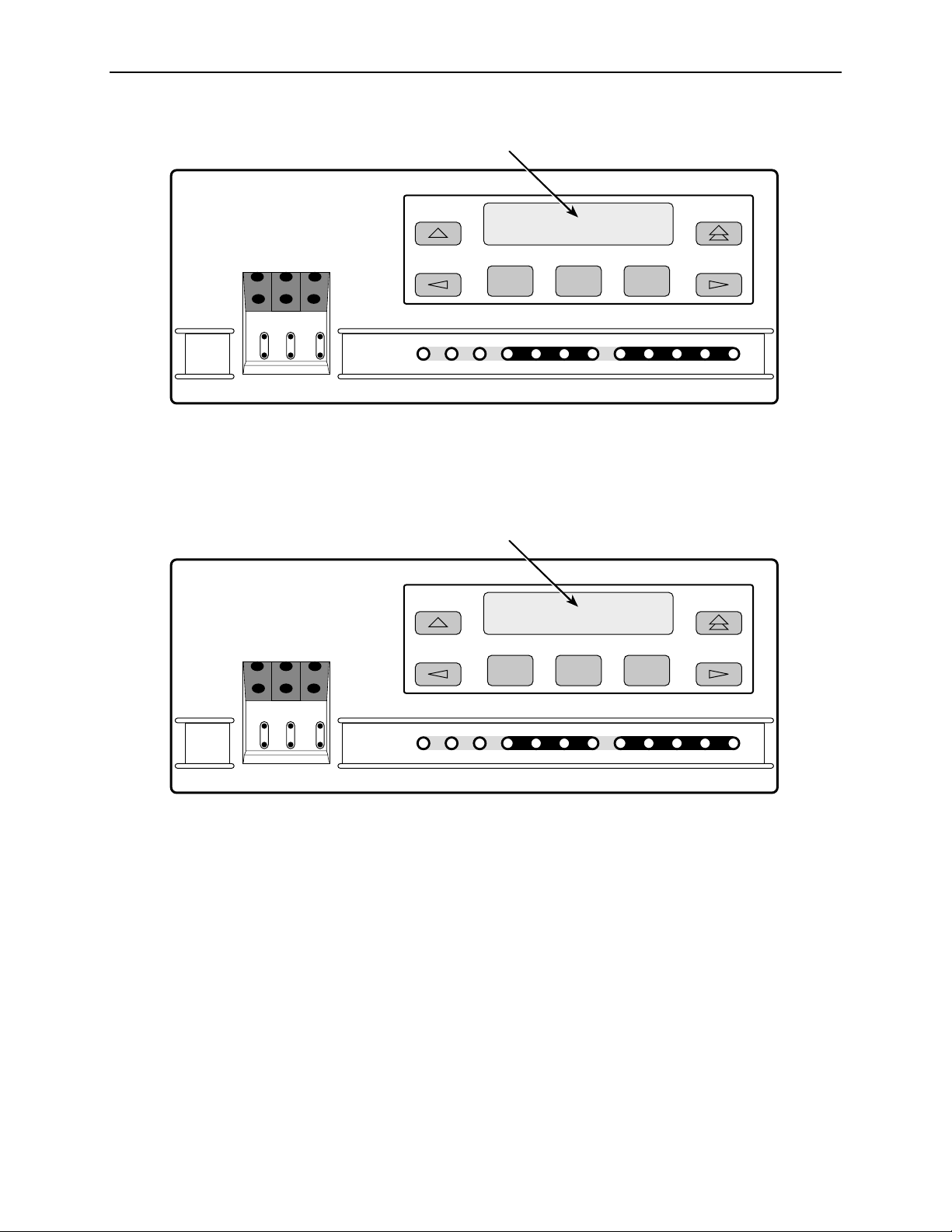
Standalone DSU/CSU Front Panel
The standalone DSU/CSU front panel contains,
One 2-line, 16-alphanumeric-character-per-line liquid crystal display (LCD)
One 7-button keypad (three Function and four directional keys)
Twelve light-emitting diodes (LEDs)
Six test jacks for the Model 3160/3164 DSU/CSU, and two test jacks for the
Model 3165 DSU/CSU
The front panels are shown in Figure 1-1, 3160 DSU/CSU Front P anel, Figure 1-2,
3164 DSU/CSU Front Panel, and Figure 1-3, 3165 DSU/CSU Front Panel.
ACCULINK
and the
.
COMSPHERE
3160-A2-GB21-90 February 2001
1-3
Page 20
1. Introduction
ACCULINK
3160
MON EQPT
NET
In
OutInOutInOut
OK
FAIL TEST SIG OOF ALRM
Figure 1-1. 3160 DSU/CSU Front Panel
LCD
F1 F2 F3
EER SIG ALRM PDVOOF BPV
NETWORK RXD
DTR TXD CTS RTS
496-14936
ACCULINK
3164
MON EQPT
NET
In
OutInOutInOut
OK
FAIL TEST SIG OOF ALRM
Figure 1-2. 3164 DSU/CSU Front Panel
LCD
F1 F2 F3
EER SIG ALRM PDVOOF BPV
NETWORK RXD
DTR TXD CTS RTS
496-14937
February 2001 3160-A2-GB21-90
1-4
Page 21
ACCULINK
3165
LCD
F1 F2 F3
NET
MON
In
Out
OK
FAIL TEST SIG OOF ALRM
NETWORK
Figure 1-3. 3165 DSU/CSU Front Panel
EER
DTR TXD CTS RTS
RXD
PORT
1. Introduction
495-14567-01
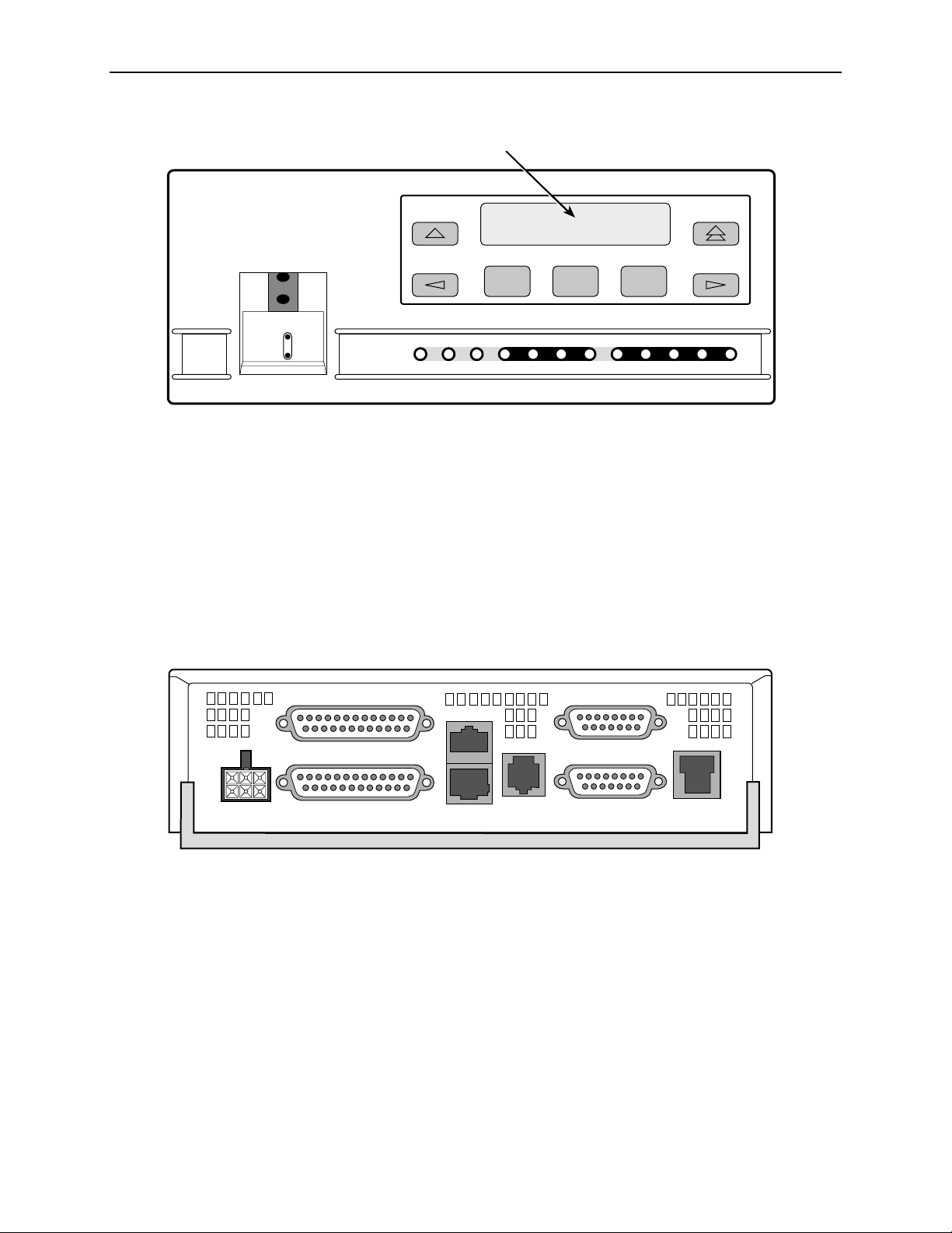
Standalone DSU/CSU Rear Panel
The standalone DSU/CSU rear panel contains the connectors required for the
operation of the DSU/CSU (Figure 1-4, 3160 DSU/CSU Rear Panel, Figure 1-5,
3164 DSU/CSU Rear Panel, and Figure 1-6, 3165 DSU/CSU Rear Panel). The
connectors and their functions are listed in Table 1-1, Standalone DSU/CSU Rear
Panel Connectors.
PORT 2
POWER
Figure 1-4. 3160 DSU/CSU Rear Panel
PORT 1
AUX
COM DSX-1MODEM
EXT CLK
NET
99-16234
3160-A2-GB21-90 February 2001
1-5
Page 22
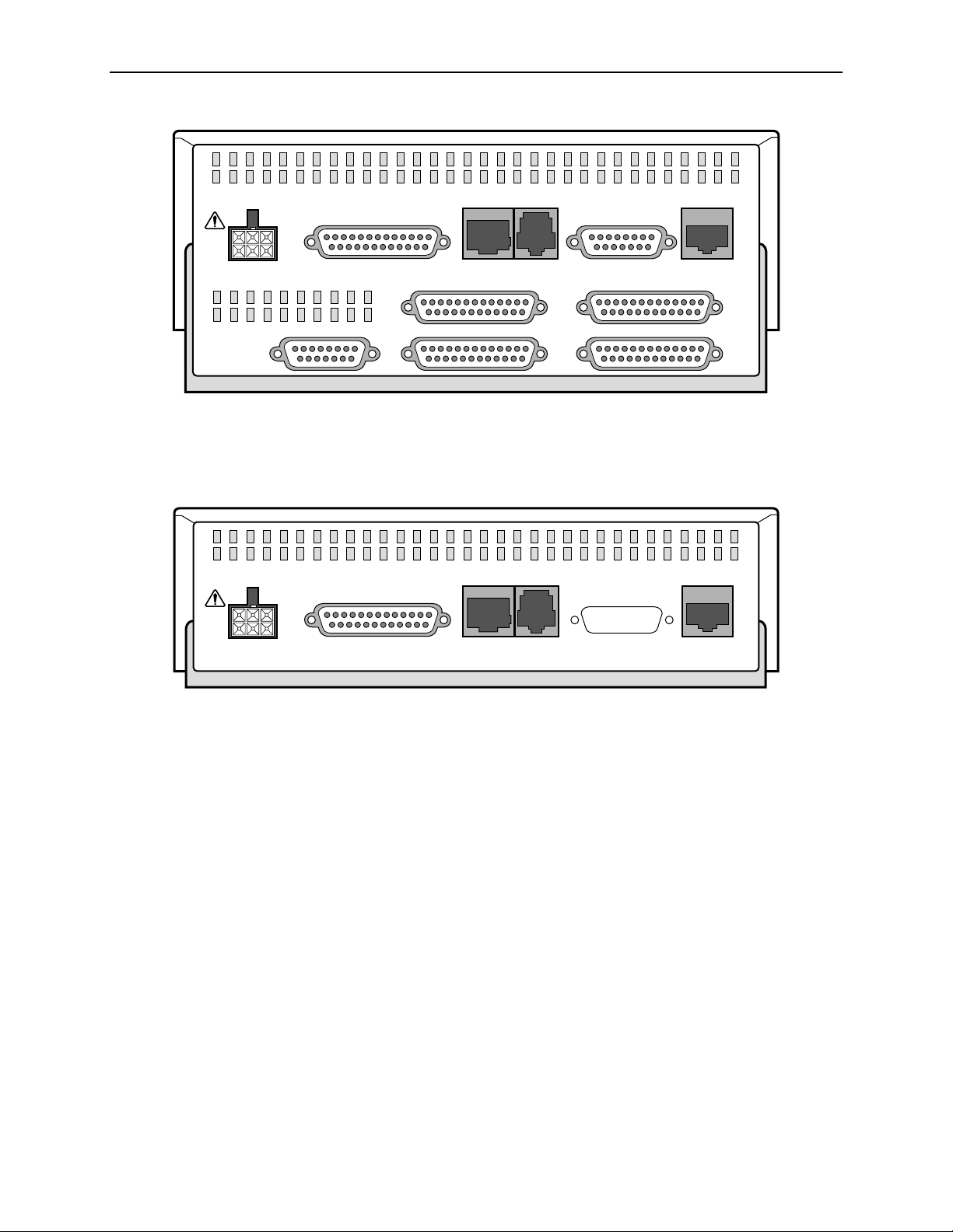
1. Introduction
POWER
NEC
CLASS 2
INPUT
AUX PORT
CAUTION:
AUX PORT OR COM PORT MUST NOT BE CONNECTED TO PSTN OR T1 NETWORK
Figure 1-5. 3164 DSU/CSU Rear Panel
POWER
NEC
CLASS 2
INPUT
PORT 1
CAUTION:
AUX PORT OR COM PORT MUST NOT BE CONNECTED TO PSTN OR T1 NETWORK
COM PORT MODEM
COM PORT MODEM
DTE
NETWORK
PORT 4PORT 3
PORT 2PORT 1CLOCK IN
494-14564
NETWORK
Figure 1-6. 3165 DSU/CSU Rear Panel
495-14565-01
February 2001 3160-A2-GB21-90
1-6
Page 23

1. Introduction
Table 1-1. Standalone DSU/CSU Rea r Panel Conn ector s
Name Function
POWER Supplies power to the DSU/CSU by providing an
attachment for the ac power module or the optional dc
power cable (+24 or –48 Vdc).
AUX PORT Supports SNMP LAN Adapter or daisy-chain connections.
COM PORT Provides access to a locally connected PC, ASCII terminal
or printer, SNMP management link, or async terminal
interface.
MODEM Provides a connection to the integral modem for access to
a remotely connected PC, ASCII terminal or printer, SNMP
management link, or async terminal interface.
NETWORK Provides access to the T1 network.
DTE (Model 3160/3164) Provides access to the DTE Drop/Insert (DSX-1) interface.
CLOCK IN (Models
3160/3164)
PORTs 1–4 Used to connect the customer's synchronous data DTE to
Used to attach an external clock to the DSU/CSU.
the DSU/CSU.
3160-A2-GB21-90 February 2001
1-7
Page 24

1. Introduction
February 2001 3160-A2-GB21-90
1-8
Page 25

Installation
Overview
2
This chapter contains information for installing your standalone DSU/CSU. It
includes application examples, cabling, and power-up information.
NOTE:
Installation instructions for the carrier-mounted DSU/CSU are located in the
ACCULINK 3151 CSU and 3161 DSU/CSU General Information Guide
COMSPHERE 3000 Series Carrier Installation Manual
the
.
and
Application Examples
The DSU/CSU acts as an interface between the T1 digital network and the
customer’s equipment.
The DSU/CSU is connected to the customer’s equipment through one of the
synchronous data ports (PORTs 1–4) or the DTE Drop/Insert (DSX-1) interface. It
is connected to the T1 digital network through the network interface.
NOTE:
The DTE Drop/Insert (DSX-1) interface is only available on 2-port and 4-port
DSU/CSUs.
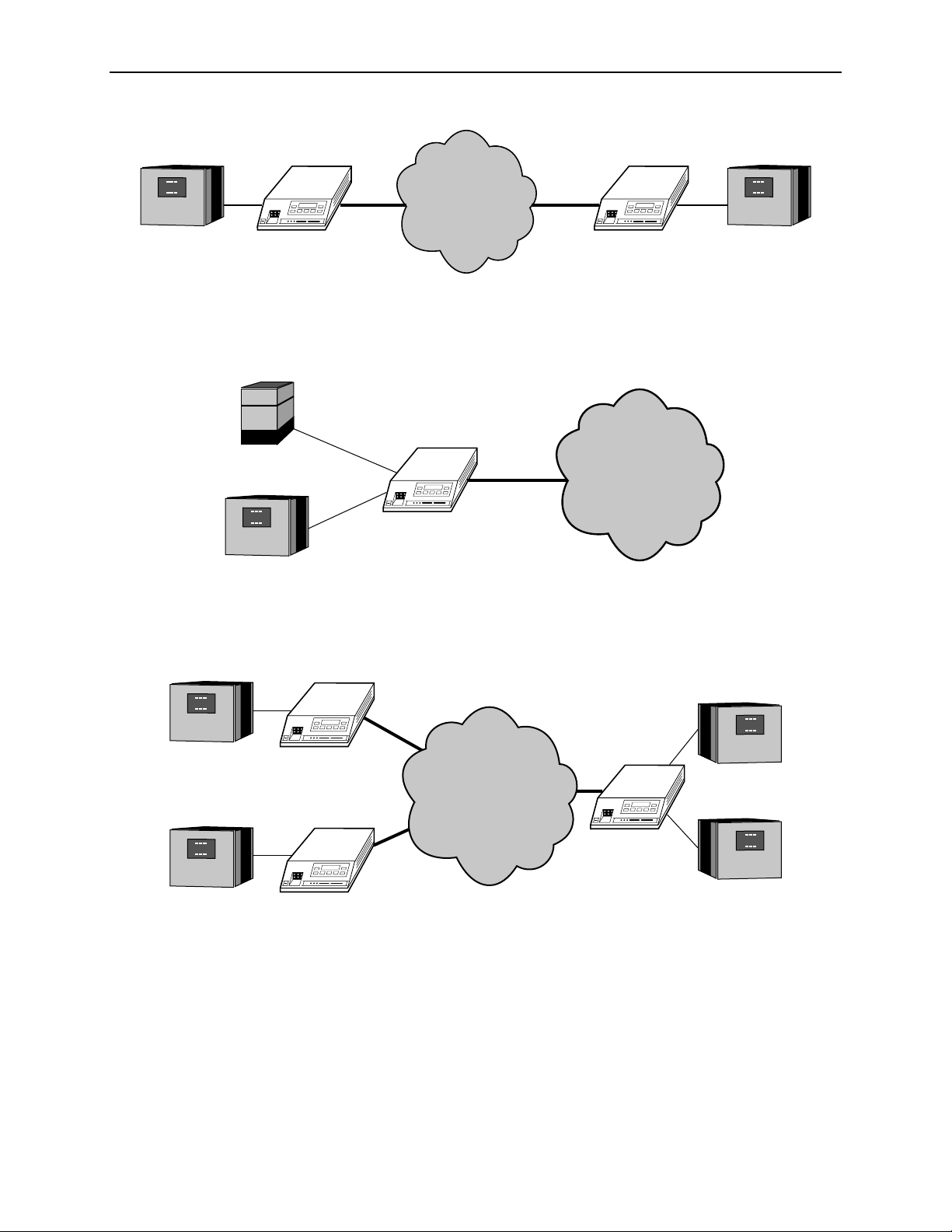
Some common applications for the DSU/CSU are:
Point-to-P oint LAN interconnection (Figure 2-1, Point-to-Point Application
Example).
Shared access to network-based services (Figure 2-2, Shared Access
Application Example).
Fractional T1 network applications (Figure 2-3, Fractional T1 Application
Example).
3160-A2-GB21-90 February 2001
2-1
Page 26
2. Installation
NETWORK
LAN
ROUTER
DSU/CSU
Figure 2-1. Point-to-Point Application Example
PBX
DSU/CSU
LAN
ROUTER
Figure 2-2. Shared Access Application Example
DSU/CSU
NETWORK
SERVICES
LAN
ROUTER
496-15003-01
496-15004-01
LAN
ROUTER
DSU/CSU
FRACTIONAL
LAN
ROUTER
NETWORK
DSU/CSU
LAN
ROUTER
DSU/CSU
LAN
ROUTER
496-15005-01
Figure 2-3. Fractional T1 Application Example
February 2001 3160-A2-GB21-90
2-2
Page 27
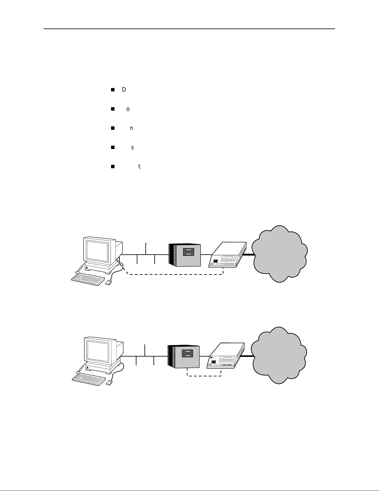
SNMP or Telnet Connection Examples
The DSU/CSU can be connected to an SNMP or Telnet system in a number of
ways. Some examples include:
Directly connecting the COM port to the SNMP or Telnet device (Figure 2-4,
Direct Connection).
Connecting the COM port to a network device (e.g., a router) (Figure 2-5,
Connection through a Router).
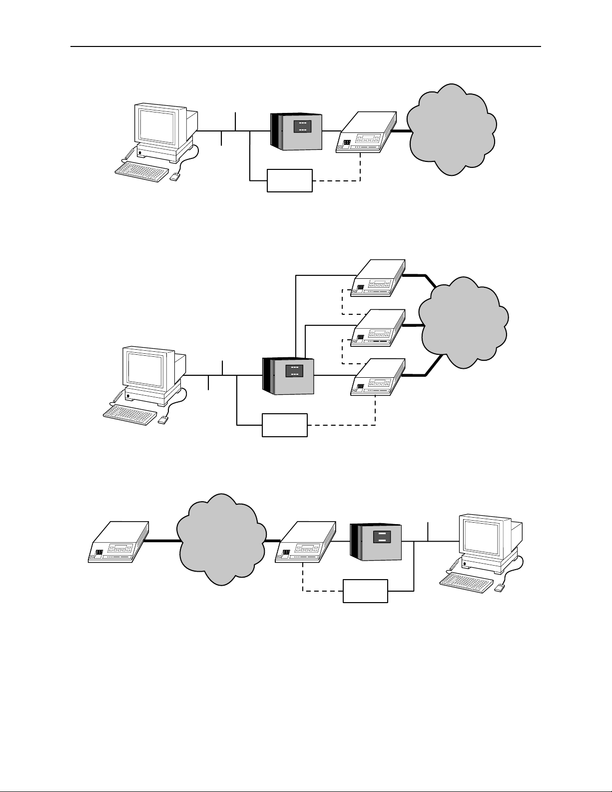
Connecting the COM port or the AUX port to an external LAN Adapter for
Ethernet connectivity (Figure 2-6, Connection through a LAN Adapter).
Daisy chaining the COM port of one device to the AUX port of the other
(Figure 2-7, LAN Adapter and Daisy Chaining).
Remotely accessing the DSU/CSU through the Facility Data Link (FDL) or the
synchronous data port’s Embedded Data Link (EDL) (Figure 2-8, Remote
Access through FDL/EDL).
NOTE:
2. Installation
EDL is only available on 2-port and 4-port DSU/CSUs.
ETHERNET
PPP/SLIP
LAN
ROUTER
DSU/CSU
Figure 2-4. Direct Connection
ETHERNET
LAN
ROUTER
PPP/SLIP
DSU/CSU
P
ara
dyn
e
NETWORK
496-15006-01
NETWORK
496-15007-01
Figure 2-5. Connection through a Router
3160-A2-GB21-90 February 2001
2-3
Page 28
2. Installation
ETHERNET
LAN
ROUTER
LAN
ADAPTER
DSU/CSU
PPP
Figure 2-6. Connection through a LAN Adapter
DSU/CSU
ETHERNET
LAN
ROUTER
PPP
PPP
DSU/CSU
DSU/CSU
NETWORK
496-15008-01
NETWORK
FDL/EDL
LAN
ADAPTER
PPP
Figure 2-7. LAN Adapter and Daisy Chaini n g
DSU/CSUDSU/CSU
LAN
ROUTER
NETWORK
PPP
LAN
ADAPTER
Figure 2-8. Remote Access through FDL/EDL
496-15009-01
ETHERNET
496-15010-01
February 2001 3160-A2-GB21-90
2-4
Page 29

Important Instructions
Read and follow all warning notices and instructions marked on the DSU/CSU or
included in this guide.
2. Installation
For a complete listing of the safety instructions, see
at the beginning of this guide.
!
HANDLING PRECAUTIONS FOR STATIC-SENSITIVE
DEVICES
This product is designed to pro tect sensitive components from damage
due to electrostatic discharge (ESD) during normal operation. When
performing installation procedures, however, take proper static control
precautions to prevent damage to equipment. If you are not sure of the
496-15104
proper static control precautions, contact your nearest sales or service
representative.
Optional Power Sources
The DSU/CSU is typically powered by the ac power module. Use the
following procedures only if you want to use an optional SELV (Safety Extra
Low Voltage) dc power source.
Using the optional dc power cable, the DSU/CSU is capable of operating on either
a +24 Vdc power source, –48 Vdc single source battery, or –48 Vdc redundant
source batteries (for power backup). To use dc power, choose one of the following
power supply types.
Impor tant Sa fety Instruc tio ns
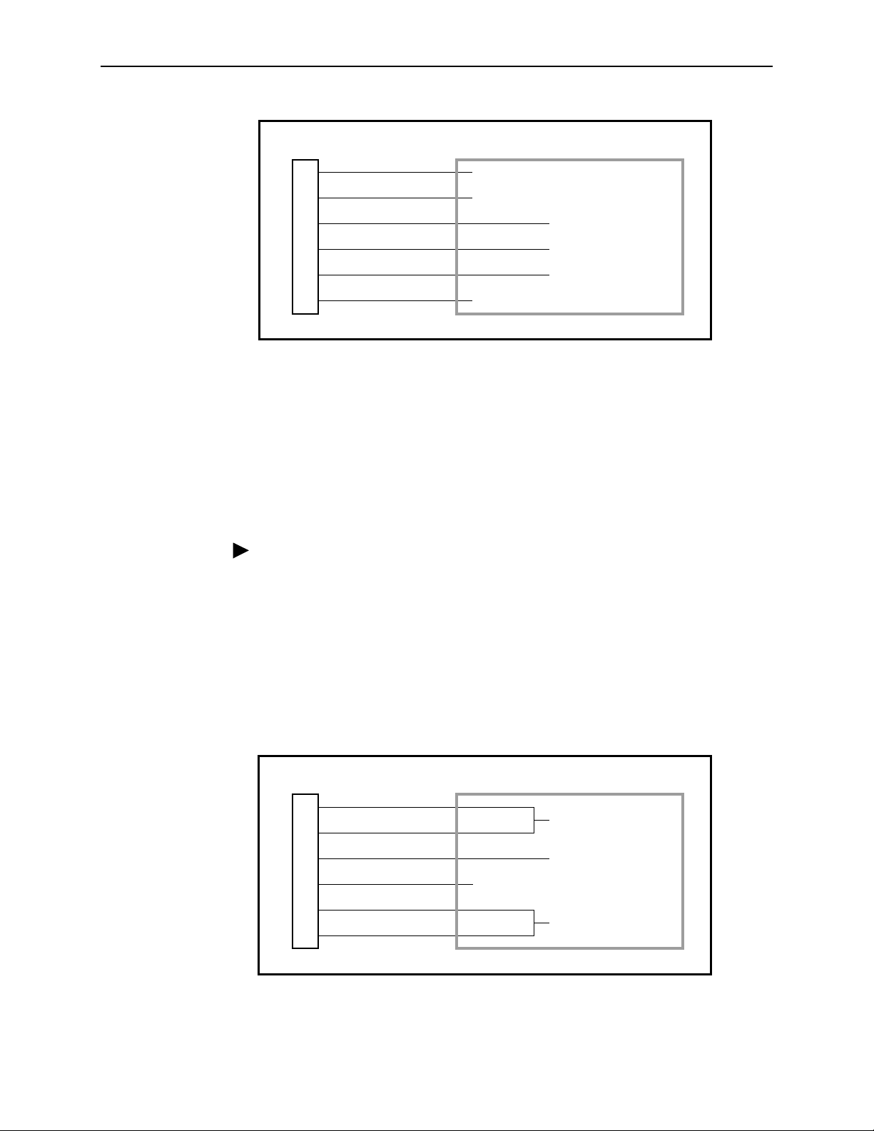
Installing the +24 Vdc Power Supply
To install the DSU/CSU using a +24 Vdc SELV power supply, refer to Figure 2-9,
+24 Vdc Power Supply Pinouts, and use the following procedure.
Procedure
To install the +24 Vdc power supply:
1. Connect the green wire to a suitable ground.
2. Connect the white wire to the +24 Vdc return.
3. Connect the orange wire to the +24 Vdc source.
4. Cut the black, red, and blue wires off at the outer insulation.
5. Plug the power connector into the DSU/CSU.
3160-A2-GB21-90 February 2001
2-5
Page 30
2. Installation
DSU/CSU POWER
PLUG
1
2
3
4
5
6
BLACK
RED
GREEN
WHITE
ORANGE
BLUE
Figure 2-9. +24 Vdc Power Supply Pinouts
Installing the Single –48 Vdc Power Supply
TO CUSTOMER-SUPPLIED BATTERY
X
X
GROUND
+24 VDC RETURN
+24 VDC SOURCE
X
99-14298-02
To install the DSU/CSU using a single source –48 Vdc SEL V pow er supply , ref er to
Figure 2-10, –48 Vdc Single Source Power Supply Pinouts, and use the following
procedure.
Procedure
To install the –48 Vdc sing le sou r ce power sup pl y:
1. Connect the black and red wires to the –48 Vdc return source.
2. Connect the green wire to a suitable ground.
3. Connect the orange and blue wires to the –48 Vdc input source.
4. Cut the white wire off at the outer insulation.
5. Plug the power connector into the DSU/CSU.
DSU/CSU POWER
PLUG
1
2
3
4
5
6
BLACK
RED
GREEN
WHITE
ORANGE
BLUE
TO CUSTOMER-SUPPLIED BATTERY
–48 VDC RETURN
GROUND
X
–48 VDC INPUT
99-14299-02
Figure 2-10. –48 Vdc Single Source Power Supply Pinouts
February 2001 3160-A2-GB21-90
2-6
Page 31
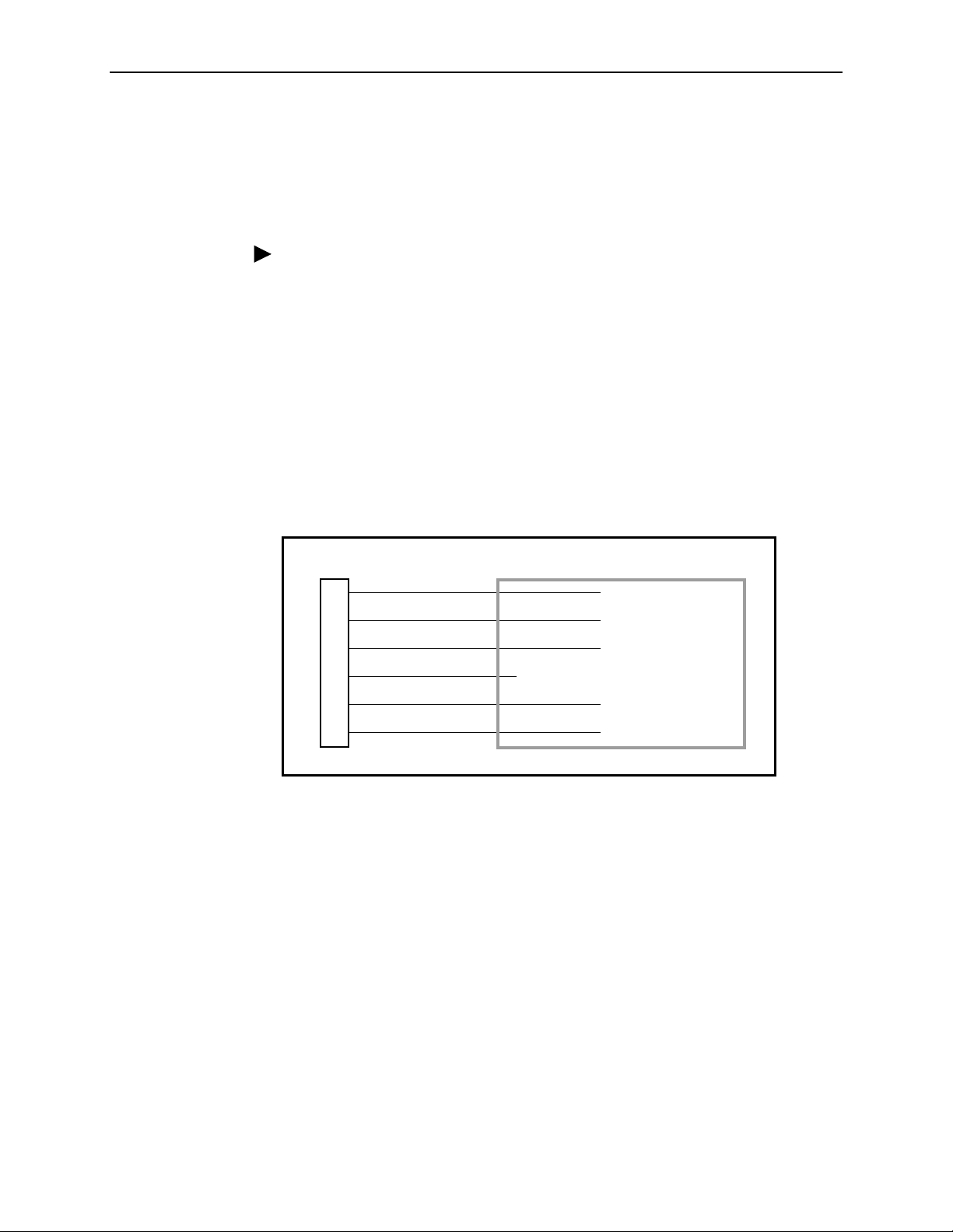
Installing the Redundant –48 Vdc Power Supply
To install the DSU/CSU using a redundant –48 Vdc SELV power supply, refer to
Figure 2-11, –48 Vdc Redundant Source Power Supply Pinouts, and use the
following procedure.
Procedure
To install the redundant –48 Vdc power supply:
1. Connect the black wire to the –48 Vdc return source B.
2. Connect the red wire to the –48 Vdc return source A.
3. Connect the green wire to a suitable ground.
4. Connect the orange wire to the –48 Vdc input source B.
5. Connect the blue wire to the –48 Vdc input source A.
6. Cut the white wire off at the outer insulation.
7. Plug the power connector into the DSU/CSU.
2. Installation
DSU/CSU POWER
PLUG
1
2
3
4
5
6
BLACK
RED
GREEN
WHITE
ORANGE
BLUE
TO CUSTOMER-SUPPLIED BATTERY
–48 VDC RETURN B
–48 VDC RETURN A
GROUND
X
–48 VDC INPUT B
–48 VDC INPUT A
Figure 2-11. –48 Vdc Redundant Source Power Supply Pinouts
99-14300-02
3160-A2-GB21-90 February 2001
2-7
Page 32

2. Installation
Cabling Examples
The DSU/CSU is supplied with an ac power module and a VF cable for the integral
modem.
TERMINAL
COM
PORT
PORT 2
POWER
PORT 1
MODEM
MODEM
PORT
AUX
COM DSX-1MODEM
Optional cables are described in Appendix D,
Pin Assignments
.
Figure 2-12, Cabling Examples, illustrates some cabling examples.
OR
OR
MANAGER
3164 DSU/CSU
EXT CLK
NETWORK
PORT
DSU/CSU
NET
3160
PSTN
MODEM
PORT
NETWORK
PORT
MODEM
PC
SNMP
FRONT
PANEL
T1 NETWORK
NETWORK
PORT
COM PORT MODEM
AUX PORT OR COM PORT MUST NOT BE CONNECTED TO PSTN OR T1 NETWORK
NETWORK
DTE
PORT 4PORT 3
PORT 2PORT 1CLOCK IN
POWER
SERIAL
PORT
3164
DSU/CSU
COM PORT
POWER
NEC
CLASS 2
INPUT
AUX PORT
CAUTION:
POWER
TO
ROUTER
T1 OR SERIAL CONNECTIONS
DIAL CONNECTIONS
SNMP
MANAGER
OR
OR
TERMINAL
99-16250
Figure 2-12. Cabling Examples
February 2001 3160-A2-GB21-90
2-8
Page 33

Power-Up Self-Test
After you connect the DSU/CSU to a power source, the unit performs the power-up
self-test to ensure that it is in good working order. The DSU/CSU performs this test
on itself upon power-up or after a device reset, unless it has been disabled by the
Self-Test configuration option (see Appendix C,
The self-test includes a basic processor test, a limited memory test, a code
checksum test, and basic verification tests of the internal components. The front
panel LCD displays the progress and pass/fail status of these power-up tests.
The power-up self-test consists of the following steps:
1. Once the DSU/CSU is plugged in, the In Progress screen appears and the Fail
LED blinks ON and Off continuously.
Self-Test:
In Progress
Configuration Options
2. Installation
).
F1
F2
F3
2. All the LEDs then start to flash simultaneously in the pattern twice ON, then
Off. Then, the LCD begins to flash characters and numbers in the same
pattern, alternating with the flashing LEDs.
3. If the self-test is successful, the Passed screen appears for one second, the
Fail LED turns Off and the OK LED lights.
Self-Test:
Passed
F1
F2 F3
3160-A2-GB21-90 February 2001
2-9
Page 34

2. Installation
If the self-test fails, the Failed screen appears for five seconds. The Fail LED
lights, and an eight-digit failure code (
xxxxxxxx
) is displayed for use by service
personnel to determine the cause of the self-test failure. The DSU/CSU
continues to try to operate. If you are in doubt about the results of the self-test,
use the Self-Test Health command to display the status of this test (see
Self-Test Health
Self-Test:
Failed
in Chapter 4,
xxxxxxxx
Maintenance
).
F1
F2 F3
4. The top-level menu screen appears.
DSU ESF
Stat Test Cnfig
F1
F2
F3
February 2001 3160-A2-GB21-90
2-10
Page 35

Operation
Overview
3
This chapter contains information for operating your DSU/CSU. It includes a
description of the front panel and sample procedures for configuring the
DSU/CSU.
NOTE:
Additional information for the carrier-mounted DSU/CSU is located in the
ACCULINK 3151 CSU and 3161 DSU/CSU General Information Guide
COMSPHERE 3000 Series Carrier Installation Manual
the
.
and
Using the Front Panel
The standalone DSU/CSU front panel (Figure 3-1, Standalone DSU/CSU Front
Panel) consists of an LCD, a keypad, test jacks, and 12 LEDs. The
carrier-mounted DSU/CSU faceplate contains test jacks and 12 LEDs, however,
the LCD and keypad are located on the Shared Diagnostic Control Panel (SDCP)
of the 3000 Series Carrier. For more information about the SDCP, refer to the
COMSPHERE 3000 Series Carrier Installation Manual
NOTE:
You can display a graphical representation of the DSU/CSU front panel on an
attached PC (see Appendix G,
.
Front Panel Emulation
).
3160-A2-GB21-90 February 2001
3-1
Page 36

3. Operation
ACCULINK
3160
LCD
F1 F2 F3
MON EQPT
NET
In
OutInOutInOut
OK
FAIL TEST SIG OOF ALRM
Figure 3-1. Standalone DSU/CSU Front Panel
EER SIG ALRM PDVOOF BPV
NETWORK RXD
DTR TXD CTS RTS
496-14936
LCD
The LCD (Figure 3-2, LCD) displays two types of data:
Messages such as alarms, command/test completion, and action in progress
Front panel menu tree information (see Appendix A,
Front Panel Menu
)
F1
F2 F3
Figure 3-2. LCD
The LCD displays status messages as requested via the Device Health and Status
branch of the front panel menu (see
Maintenance
). In addition, the highest level status message appears on the front
Device Health and Status
in Chapter 4,
panel automatically if no front panel action has occurred at the DSU/CSU for the
past five minutes.
The LCD also lists commands, configuration options, and test results. In most
cases, the top line shows the command or option name and default value, while
the second line displays options and responses. When a response is required,
select from the options displayed directly above the Function keys (F1, F2, F3);
make your choice by pressing the corresponding Function key.
February 2001 3160-A2-GB21-90
3-2
Page 37

Keypad
3. Operation
The 7-button keypad (Figure 3- 3, Keypad) enables you to navigate through the
menu tree and select choices presented on the second line of the LCD.
F1
F2 F3
Figure 3-3. Keypad
Use the key to mov e up the menu.
F1
F2
F3
Use the key to exit any part of the menu in which you may be operating. You
immediately return to the top-level menu screen shown on the front panel menu
(see Appendix A,
Front Panel Menu
F1
F2
).
F3
Use the Function (F1, F2, F3) keys to make selections from the choices presented
on the second line of the LCD. When this line presents choices, it is generally
divided into three sections, each displayed directly above one of the Function keys.
When your choice appears above one of the Function keys, press that key to
select that choice.
F1
3160-A2-GB21-90 February 2001
F2 F3
3-3
Page 38

3. Operation
The scroll keys ( and ) serve one of two functions, depending on whether a
menu screen or a data entry screen appears on the front panel.
For data entry screens, the key scrolls one character to the left while the
key scrolls one character to the right.
For menu screens, the key scrolls to the previous menu choice while the
key scrolls to the next menu choice.
Test Jacks
F1
F2 F3
If a choice is available to the left of the screen, the character ← appears on the top
line. If a choice is available to the right of the screen, the → character appears on
the top line. If choices are available to both the right and the left of the screen, two
arrows appear (⇔). The arrows indicate that you must use the scroll keys to bring
the additional options onto the screen.
Test jacks are located on the DSU/CSU front panel (Figure 3-4, Test Jacks
(Standalone DSU/CSU)). These are described in
Maintenance
. (The 3165 provides only the Network Monitor In and Network
Test Jacks
in Chapter 4,
Monitor Out test jacks.)
NET MON EQPT
In
OutInOutInOut
496-14808
Figure 3-4. Test Jacks (Standalone DSU/CSU)
February 2001 3160-A2-GB21-90
3-4
Page 39

LEDs
3. Operation
There are twelve LEDs on the DSU/CSU front panel. The five LEDs on the right
(Figure 3-5, DSU/CSU LEDs) are shared between the DTE Drop/Insert (DSX-1)
interface and the data ports. Refer to
for LED Display
on page 3-12 to choose which port’s status the LEDs display.
Selecting the DTE Drop/Insert or Data Port
NOTE:
The DTE Drop/Insert (DSX-1) interface is only available on 2-port and 4-port
DSU/CSUs.
OK
FAIL
TEST SIG OOF ALRM
EER SIG ALRM PDVOOF BPV
NETWORK TXD
DTR RXD CTS RTS
493-14301
Figure 3-5. DSU/CSU LEDs
A green LED indicates normal operation. A yellow LED indicates a warning (for the
DTE Drop/Insert interface) or activity (for the data ports). Conditions are sampled
every tenth of a second.
The twelve front panel LEDs are grouped into four sections to indicate the status of
the:
System LEDs (Table 3-1)
Network Interface LEDs (Table 3-2)
DTE Drop/Insert (DSX-1) Interface LEDs (Table 3-3)
Data Port LEDs (Table 3-4)
3160-A2-GB21-90 February 2001
3-5
Page 40

3. Operation
Table 3-1. System LEDs
Name Color Meaning
OK
FAIL
TEST
Green Indicates the current operational state of the DSU/CSU.
ON:
The DSU/CSU is operational and has power.
OFF:
The DSU/CSU is performing a power-up self-test or a
system failure has occurred.
BLINKING :
F AST BLINK:
selected by the SDCP.
Yellow Indicates a system failure or a self-test.
ON:
OFF:
BLINKING
Yellow A system test is in progress.
ON:
the network, or externally.
OFF:
A software downlo ad is in prog ress.
The carrier-mounted DSU/CSU is currently
A device error/fault is detected or a reset has just occurred.
No system failures are detected.
: A self-test is in progress.
A loopback or pat tern test has be en ini tiated eithe r lo cally, by
No tests are active.
Table 3-2. Network Interface LEDs
Name Color Meaning
SIG
OOF
ALRM
EER
Green Monitors the signal being received from the network.
ON:
A recoverable signal is being received from the network.
OFF:
The signal can not be reco v er ed from th e netw ork (a L oss o f
Signal condition exists).
Yellow Monitors Out Of Frame (OOF) conditio ns on the received
network signal.
ON:
At least one OOF was detected on the signal during the
sampling period.
OFF:
No OOFs were detected on the signal during the sampling
period.
Yellow Indicates whether an alarm condition exists on the received
network signal.
ON:
An alarm condition (LOS, LOF, EER, Yellow, AIS) exists on
the received network signal. Use the Device Health and Status
command to determine the alarm type.
OFF:
No alarm condition exists on the network interface signal.
Yellow Indicates the Excessive Error Rate (EER) has been exceeded on
the network interface.
This LED is only valid when ESF framing is being used.
NOTE:
ON:
The EER has been exceeded on the network interface.
OFF:
The EER has not been exceeded on the network interface.
February 2001 3160-A2-GB21-90
3-6
Page 41

3. Operation
NOTE:
The DTE Drop/Insert (DSX-1) interface is only available on 2-port and 4-port
DSU/CSUs.
Table 3-3. DTE Drop/Insert (DSX-1) Interface LEDs
Name Color Meaning
SIG
OOF
ALRM
PDV
Green Monitors the signal being received from the DTE Drop/Insert
(DSX-1) interface.
ON:
A recoverable signal is being received from the DTE
Drop/Insert (DSX-1) interface.
OFF:
The signal cannot be recovered from the DTE Drop/Insert
(DSX-1) interface (a Loss of Signal condition exists) .
Yellow Monitors Out Of Frame (OOF) conditio ns on the received DTE
Drop/Insert (DSX-1) signal.
ON:
At least one OOF was detected on the signal during the
sampling period.
OFF:
No OOFs were detected on the signal during the sampling
period.
Yellow Indicates whether an alarm condition exists on the received DTE
Drop/Insert (DSX-1) signal.
ON:
An alarm condition (LOS, LOF, EER, Yellow, AIS) exists on
the received DTE Drop/Insert (DSX-1) signal. Use the Device
Health and Status command to determine the alarm type.
OFF:
No alarm condition exists on the DTE Drop/Insert (DSX-1)
interface signal.
Yellow Monitors Pulse Density Violations (PDV) on the received DTE
Drop/Insert (DSX-1) signal.
ON
: At least one PDV was detected (and corrected) on the
received DTE Drop/Insert (DSX-1) signal during the sampling
period.
OFF:
No PDVs were detected on the received DTE Drop/Insert
(DSX-1) signal during the sampling period.
BPV
3160-A2-GB21-90 February 2001
Yellow Monitors Bipolar Violations (BPV) on the received DTE
Drop/Insert (DSX-1) signal.
ON:
At least one BPV was detected (and corrected) on the
received DTE Drop/Insert (DSX-1) signal during the sampling
period.
OFF:
No BPVs were detected on the received DTE Drop/Insert
(DSX-1) signal during the sampling period.
3-7
Page 42

3. Operation
Table 3-4. Data Port LEDs
Name Color Meaning
DTR
TXD
RXD
CTS
Green Monitors the state of interchange circuit CD (CCITT 108/1, /2)
Data Terminal Ready received from the synchronous data DTE.
ON:
DTR is being asserted by the synchronous data DTE.
OFF:
DTR is not being asserted.
Yellow Monitors activity on interchange circuit BA (CCITT 103)
Transmitted Data. This is the data sent from the synchronous
data DTE to the data port on the DSU/CSU.
ON:
Ones are being received from the synchronous data DTE.
OFF:
Zeros are being received from the synchronous data DTE.
CYCLING:
synchronous data DTE.
Yellow Monitors activity on interchange circuit BB (CCITT 104)
Received Data. This is data sent to the synchronous data DTE
from the data port on the DSU/CSU.
ON:
OFF:
CYCLING:
synchronous data DTE.
Yellow Monitors the state of interchange circuit CB (CCITT 106)
Clear-to-Send sent to the synchronous data DTE.
ON:
OFF:
Both ones and zeros are being received from the
Ones are being sent to the synchronous data DTE.
Zeros are being sent to the synchronous data DTE.
Both ones and zeros are being sent to the
CTS is being asserted by the DSU/CSU.
CTS is not being asserted.
–
–
–
–
RTS
Yellow Monitors the state of interchange circuit CA (CCITT 105)
Request-to-Send received from the synchronous data DTE.
ON:
RTS is being asserted by the synchronous data DTE.
OFF:
RTS is not being asserted.
–
February 2001 3160-A2-GB21-90
3-8
Page 43

NOTE:
3. Operation
The following procedures are examples only.
depending on the model of the DSU/CSU.
Displaying Unit Identity
The identity of the DSU/CSU (serial number, model number, software revision
level, hardware revision level, and customer identification) is available through the
Status branch of the front panel menu (see Appendix A,
The customer identification is the only identity number you can change.
Procedure
To display the DSU/CSU’s identity (ID):
1. From the top-level menu screen, select Stat.
DSU ESF
Stat Test Cnfig
F1
F2 F3
Screen displays may vary
Front Panel Menu
).
2. From the Status screen, press the key until the ID selection appears on the
screen.
3. Select ID.
Status:
TStat LED ID
F1
F2 F3
4. The following screens appear in the order listed each time you press the
key .
Identity:
xxxxxxx
Ser=
F1
Identity:
Mod=
F2 F3
xxxx-xx-xxx
F1
3160-A2-GB21-90 February 2001
F2 F3
3-9
Page 44

3. Operation
Identity:
Cust ID=
xxxxxxxx
F1
Identity:
SRev=
F1
Identity:
CCA1=
F1
Identity:
CCA2=
F1
F2
xx.xx.xx
F2
xxxx-xxx
F2 F3
xxxx-xxx
F2 F3
F3
F3
February 2001 3160-A2-GB21-90
3-10
Page 45

Setting Customer Identification
The customer identification is the only identity number you can change. It is used
to uniquely identify the DSU/CSU.
Procedure
To change the customer identification (CID):
1. From the top-level menu, press the key until the Ctrl selection appears on
the screen.
2. Select Ctrl.
3. From the Control screen, press the key until the CID selection appears on
the screen.
4. Select CID.
Control:
Reset CID Passwd
3. Operation
F1
F2 F3
5. Use the and keys to position the cursor under the desired character.
You must enter a character before the moves the cursor to the next space
to the right.
CustID:
xxxxxxxx
Up Down Save
F1
F2
F3
6. Enter the desired ID. Press F1 (Up) and F2 (Down) to scroll up and down
through the valid characters/numbers for the customer ID. Valid characters are
0
through 9, #, -, ., /, A to Z, and blank space. Press F3 (Save) to save the ID.
3160-A2-GB21-90 February 2001
3-11
Page 46

3. Operation
Selecting the DTE Drop/Insert or Data Port for LED Display
Use the LED command on the Control branch to select which port’s (DTE
Drop/Insert or data port) status appears on the five shared LEDs on the front
panel.
Procedure
To select a port for LED display:
1. From the top-level menu screen, press the key until the Ctrl selection
appears on the screen.
2. Select Ctrl.
3. From the Control screen, select LED.
Control:
Call Rel LED
F1
F2
F3
The currently selected port name appears on the top line of the LCD. DTE
indicates the DTE Drop/Insert (DSX-1) port.
LED Dsply: DTE
DTE Prt1 Prt2
F1
F2
F3
4. From the LED Dsply screen, press the Function key that corresponds to the
DTE Drop/Insert (DSX-1) or data port for which you want the LEDs to display.
Use the scroll keys, if necessary.
Select DTE to monitor the DTE Drop/Insert (DSX-1) port’s SIG, OOF, ALRM,
PDV, and BPV status signals on the shared LEDs.
Select a particular data port to monitor the data port’s DTR, TXD, RXD, CTS,
and RTS control signals on the shared LEDs.
February 2001 3160-A2-GB21-90
3-12
Page 47

Displaying LED Conditions
The same conditions monitored by the front panel LEDs can also be monitored by
the LED command. This command is most useful when the DSU/CSU is being
accessed remotely (see Appendix G,
Panel Emulation, no LEDs are shown on the PC’s screen; you must use the Stat
command procedure described below to get LED information.
NOTE:
Front Panel Emulation
3. Operation
). When using Front
The following procedure is an example only.
Screen displays may vary
depending on the model of the DSU/CSU.
Procedure
To display LED conditions on the front panel screen:
1. From the top-level menu screen, select Stat.
2. From the Status screen, press the key until the LED selection appears on
the screen.
3. From the Status screen, select LED .
Status:
Perf TStat LED
F1
4. From the Select LEDs screen, press the Function key that corresponds to T1
interface or the data port for which you want to display LEDs. Use the scroll
keys, if necessary.
F2 F3
Select LEDs:
T1 Prt1 Prt2
F1
F2
If you chose T1, the LED Display screen lists the LED signals, two at a time,
on the second line. A vertical bar at the left of the LED name indicates the
condition is ON, while an underscore indicates the condition is Off.
LED Display:
_Test _NetSig
F1
3160-A2-GB21-90 February 2001
F2 F3
F3
3-13
Page 48

3. Operation
If you chose a port, the Port n LEDs screen lists the LED signals, two at a time,
on the second line. A vertical bar at the left of the LED name indicates the
condition is ON, while an underscore indicates the condition is Off.
Port n LEDs:
_DTR _TXD
F1
5. Use the and keys to scroll LED names onto the screen.
Changing Configuration Options
The DSU/CSU is an intelligent device that displays only valid options for the
current configuration. Therefore, you are only presented with menu choices that
are consistent with the current configuration and operational state of the
DSU/CSU; invalid combinations of configuration options do not appear. For
example, menus displayed for the Model 3160 (2 ports) and the Model 3164
(4 ports) differ due to the number of ports available. Also, if the DTE Drop/Insert
(DSX-1) interface selection is disabled, many of the menu choices do not appear.
Be aware that although all options are shown in this guide, what you see on your
DSU/CSU varies with your configuration.
The DSU/CSU offers configuration options located in the following memory areas:
Active (Activ)
DSU/CSU. Before a configuration option set becomes active for the DSU/CSU,
you must save the set to the Active area. When the DSU/CSU is shipped from
the factory, the Active configuration option set is identical to the Factory set.
This area can be written to and controls the current operation of the device.
– This is the configuration option set currently active for the
F2
F3
Customer 1 (Cust1)
– This is the first of two sets of customer-defined
configuration options. This area can be written to.
Customer 2 (Cust2)
– This is the second of two sets of customer-defined
configuration options. This area can be written to.
Factory 1 (Fact1)
– This is a set of configuration options preset at the factory.
This set is determined by what is considered to be the most common
configuration used in the DSU/CSU market. Factory 1 options are read-only.
Factory 2 (Fact2)
– This is a set of configuration options preset at the factory.
This set is determined by what is considered to be the second most common
configuration used in the DSU/CSU market. Factory 2 options are read-only.
February 2001 3160-A2-GB21-90
3-14
Page 49

3. Operation
The configuration options are divided into functional groups. Appendix C,
Configuration Options
, contains a list of the configuration options and defaults.
These groups are:
DTE Interface Configuration Options
Port Configuration Options
Network Interface Configuration Options
Channel Configuration Options
General Configuration Options
User Interface Configuration Options
Alarm Configuratio n Option s
Management Configuration Options
The DSU/CSU arrives with two preset factory default configuration settings. These
settings are based on the following:
Factory 1
– ESF framing format with B8ZS line coding format for both the
network and the DTE Drop/Insert (DSX-1) interfaces. Data ports are
unassigned.
Factory 2
– D4 framing format with AMI line coding format for both the
network and the DTE Drop/Insert (DSX-1) interfaces. Data ports are
unassigned.
If neither of the factory default settings support your network’s configuration, you
can customize the configuration options to better suit your application.
Use the Configuration (Cnfig) branch of the front panel menu tree to display or
change DSU/CSU configuration options (see Appendix C,
Configuration Options
).
3160-A2-GB21-90 February 2001
3-15
Page 50

3. Operation
Displaying/Editing Configuration Options
Procedure
To display/edit configuration options:
1. From the top-level menu screen, select Cnfig.
DSU ESF
Stat Test Cnfig
F1
F2
F3
2. Select the configuration option set to be copied into the Edit area by using the
appropriate Function key. Use the scroll keys, if necessary.
Load from:
Activ Cust1
F1
F2 F3
3. Select Edit.
Choose Funct:
Edit Save
F1
F2 F3
4. From the Edit screen, select the functional group you want to edit by pressing
the appropriate Function key. Use the scroll keys, if necessary. (The NET
selection is shown as an example only.)
Edit:
DTE Port NET
F1
F2
F3
The configuration options for the selected functional group appear on the front
panel one option at a time. The option name appears on Line 1 with the
current value next to it. To reach other options, use the Next and Previous
selections to scroll forward and backward through the group of options.
February 2001 3160-A2-GB21-90
3-16
Page 51

NET Framing: ESF
Next D4 ESF
3. Operation
Saving Edit Changes
F1
F2
F3
5. Press the appropriate Function key to choose another value. Use the scroll
keys, if necessary.
6. Use the Save procedure to save your changes to the Active or Customer area.
Save edit changes to the Active area when you want those changes to take effect
immediately. Save edit changes to the Customer area when you want to overwrite
the existing Customer configuration options and store these changes for future
use.
NOTE:
If you attempt to exit the Edit function after making changes without performing
a Save, the DSU/CSU prompts you with
Procedure
To save edit changes:
Save Options?
Choose
Yes
or No.
1. From the Choose Funct screen (one level above the Edit screen, two levels
below the top-level menu screen), select Save.
Choose Funct:
Edit Save
F1
F2
F3
2. Choose whether you want to save to the Active, Customer 1, or Customer 2
area. Use the scroll keys, if necessary .
Save Edit to:
Activ Cust1
F1
F2
F3
3160-A2-GB21-90 February 2001
3-17
Page 52

3. Operation
Selecting/Copying to a Specific Port
For the DSU/CSU, you hav e the capability of selecting a specific port to configure,
and then (for 2-port and 4-port DSU/CSUs) copying the configuration options from
that port to another port (or to all ports).
NOTE:
The following procedure is an example only.
Screen displays may vary
depending on the model and configuration of the DSU/CSU .
Procedure
To select a specific port to configure:
1. From the top-level menu screen, select Cnfig.
2. Select the configuration option set to be copied into the Edit area by using the
appropriate Function key. Use the scroll keys, if necessary.
3. Select Edit.
4. From the Edit screen, select Port.
Edit:
DTE Port NET
F1
5. From the Port Select screen, press the Function key that corresponds to the
port you want to configure. Use the key to scroll addition ports onto the
screen, if necessary. Configure the port (see Appendix C,
Options
).
F2 F3
Configuration
Port Select:
Copy Prt1 Prt2
F1
February 2001 3160-A2-GB21-90
3-18
F2 F3
Page 53

3. Operation
Procedure
To copy the configuration options to one or all ports:
1. From the Port Select screen, select Copy.
Port Select:
Copy Prt1 Prt2
F1
2. Select the port
F2
from
which you want to copy the configuration options using
F3
the corresponding Function key.
Copy From:
Prt1 Prt2 Prt3
F1
3. Select the port
F2 F3
to
which you want to copy the configuration options using the
corresponding Function key. Or, press F1 (All) to choose to copy to all ports.
Copy To:
All Prt1 Prt2
F1
F2
F3
Configuring the DSU/CSU for SNMP or Telnet Access
To configure the DSU/CSU for SNMP or Telnet access:
Enable the SNMP agent or Telnet server within the DSU/CSU (see
Appendix C,
Select and configure the port that provides the link to the SNMP or Telnet
Configuration Options
system.
Set the Internet Protocol (IP) address and subnet mask needed to access the
DSU/CSU (see Appendix F,
Select the link layer protocol (PPP or SLIP) for the port that provides the link to
IP Network Addressing Scenarios
the SNMP or Telnet system.
For SNMP links, specify the two community names (and their access levels)
that are allowed to access the device’s Management Information Base (MIB).
For SNMP links, configure the device to send traps to the SNMP manager, if
desired.
Specify the Telnet password or SNMP validation options, if desired (see
Appendix C,
3160-A2-GB21-90 February 2001
Configuration Options
).
).
).
3-19
Page 54

3. Operation
Selecting the Port
The SNMP manager, Telnet device, or network device (e.g., a router) can be
directly connected to the communications (COM) port. An external LAN Adapter
can be connected to either the COM port or the auxiliary (AUX) port to provide
Ethernet or Token Ring connectivity. Also, the DSU/CSU can be daisy chained
together by connecting the COM port of one device to the AUX port of the other,
providing SNMP or Telnet connectivity. Use the MODEM port when accessing the
DSU/CSU through a dial-up connection.
The COM port can support either synchronous or asynchronous PPP, or
asynchronous SLIP at data rates of up to 38,400 bps. The AUX port can support
data rates up to 38,400 bps. The MODEM port can support either synchronous or
asynchronous PPP, or asynchronous SLIP at data rates of up to 2400 bps.
The example shown below assumes that the COM port is being used as the link to
the SNMP or Telnet system.
Procedure
To select the COM port as the SNMP or Telnet link:
1. From the top-level menu screen, select Cnfig.
2. Select the configuration option set to be copied into the Edit area by using the
appropriate Function key. Use the scroll keys, if necessary.
3. Select Edit.
4. From the Edit screen, press the key until the User selection appears on the
screen.
5. Select User.
Edit:
Chan Gen User
F1
F2 F3
6. Press F1 (Next) until the Com Use configuration option appears.
7. Select Mgmt to configure the COM port as the SNMP or Telnet link.
Com Use:
Next Mgmt ASCII
F1
February 2001 3160-A2-GB21-90
3-20
F2 F3
Page 55

Setting the IP Address
3. Operation
The IP address is the address used by the SNMP or Telnet system to access the
DSU/CSU (see Appendix F,
IP Network Addressing Scenarios
). For DSU/CSUs
using PPP, the IP address can be negotiated if the network device (e.g., router or
SNMP manager) supports such negotiation. The IP address is composed of four
fields with three digits per field (
xxx.xxx.xxx.xxx
).
The IP address is set for the MODEM port, the COM port, or the AUX port (with
LAN Adapter or daisy chain), depending on which one has been chosen as the
SNMP or Telnet communication link. The example below assumes that an IP
address of 010.155.111.222 is being set for the COM port. You can use the same
principles to assign any value (between 000 and 255 for each digit field) to other
ports.
Procedure
To assign an IP address to the COM port:
1. From the top-level menu screen, select Cnfig.
2. Select the configuration option set to be copied into the Edit area by using the
appropriate Function key. Use the scroll keys, if necessary.
3. Select Edit.
4. From the Edit screen, press the key until the Mgmt selection appears on
the screen.
5. Select Mgmt.
Edit:
User Alarm Mgmt
F1
F2
F3
6. From the Mgmt Config screen, select Gen.
Mgmt Config:
Gen Trap
F1
F2
F3
7. Press F1 (Next) until the Com IP Adr configuration option appears.
NOTE:
Steps 8 and 9 describe the process for entering an IP address. This
process applies to any IP address.
3160-A2-GB21-90 February 2001
3-21
Page 56

3. Operation
8. Press F2 (Edit) to edit the IP address. You have the option of using F3 (Clear)
to reset the IP address to the factory default
Com IP Adr:
Next Edit Clear
000.000.000.000
.
F1
F2
F3
9. Use the and keys to position the cursor under the digit you want to
change. Press F1 (Up) to increment the digit or F2 (Down) to decrement the
digit. In this example, you would press once to place the cursor under the
middle digit in the first digit field, then press F1 (Up) once to change the 0 to
a 1. Continue in this manner to change the other digits.
000.000.000.000
Up Down Save
F1
10. When you are through changing the IP address, you
F2 F3
must
press F3 (Save) to
save the value. Otherwise, the original value will be retained.
010.155.111.222
Up Down Save
F1
F2
F3
February 2001 3160-A2-GB21-90
3-22
Page 57

Selecting the Link Layer Protocol
Two link layer protocols, Point-to-Point Protocol (PPP) and Serial Line Internet
Protocol (SLIP), are supported for connection to an external SNMP manager,
Telnet device, or network device (e.g., a router). PPP can be used for synchronous
or asynchronous operation. SLIP can be used for asynchronous operation only.
NOTE:
The carrier-mounted DSU/CSU does not support synchronous operation on
the COM port.
The standalone DSU/CSU implementation of PPP supports the following:
Full negotiation of PPP’s Link Control Protocol (LCP).
Active negotiation of LCP when the connection is established.
Maximum Request Unit (MRU) sizes up to 1500 bytes, but the DSU/CSU will
attempt to negotiate down to 500 bytes.
The DSU/CSU provides a unique LCP magic number derived from the unit
serial number and the elapsed time.
3. Operation
Full negotiation of escape characters.
The DSU/CSU implementation of PPP does not support Link Quality Reports
(LQR), compression, encryption, Password Authentication Protocol (PAP) or
Challenge Handshake Authentication Protocol (CHAP).
The DSU/CSU implementation of SLIP supports a fixed MRU size of 1006 bytes.
Before selecting the protocol, you must first select the port to be used as the
communications link. Refer to
Selecting the Port
on page 3-20. This example
assumes that the COM port is being used as the communications link.
Procedure
To select the link layer protocol:
1. From the top-level menu screen, select Cnfig.
2. Select the configuration option set to be copied into the Edit area by using the
appropriate Function key. Use the scroll keys, if necessary.
3. Select Edit.
4. From the Edit screen, press the key until the Mgmt selection appears on
the screen.
3160-A2-GB21-90 February 2001
3-23
Page 58

3. Operation
5. Select Mgmt.
Edit:
User Alarm Mgmt
F1
F2 F3
6. From the Mgmt Config screen, select Gen.
Mgmt Config:
Gen Trap
F1
F2
F3
7. Press F1 (Next) until the Com Link configuration option appears.
8. Press F2 (PPP) or F3 (SLIP).
Com Link:
Next PPP SLIP
F1
F2 F3
Specifying the Community Name(s) and Access Type(s)
You have the capability of specifying up to two community names (community
name 1 and community name 2) to be used by external SNMP managers when
trying to access objects in the DSU/CSU’s MIB. Once you specify the community
name(s), you must then specify the type of access to the MIB that SNMP
managers in the community are permitted to have.
Procedure
To specify the community name 1 and its access type:
1. From the top-level menu screen, select Cnfig.
2. Select the configuration option set to be copied into the Edit area by using the
appropriate Function key. Use the scroll keys, if necessary.
3. Select Edit.
4. From the Edit screen, press the key until the Mgmt selection appears on
the screen.
February 2001 3160-A2-GB21-90
3-24
Page 59

5. Select Mgmt.
Edit:
User Alarm Mgmt
3. Operation
F1
F2 F3
6. From the Mgmt Config screen, select Gen.
Mgmt Config:
Gen Trap
F1
F2
F3
7. Press F1 (Next) until the CommunityName1 configuration option appears.
8. Press F2 (Edit) to edit the community name.
CommunityName1:
Next Edit Clear
F1
F2 F3
NOTE:
Steps 9 and 10 describe the process for entering text strings for Mgmt
configuration options. This process applies to entering any text strings into
Mgmt configuration options.
9. Use the and keys to position the cursor under the character you want
to change. Press F1 (Up) or F2 (Down) to scroll through the valid
numbers/characters for the text string.
public
Up Down Save
F1
F2
F3
The F1 (Up) key scrolls through the ASCII character set in the following order:
numbers (0–9), lowercase letters (a–z), uppercase letters (A–Z), space
character, ASCII symbols (ascending order, based on ASCII code), and the
End of Line symbol (← ) The ← erases all characters to the right of the cursor.
10. When you are through changing the community name, you
must
press F3
(Save) to save the value. Otherwise, the original value will be retained.
11. Press F1 (Next) until the Access 1 configuration option appears.
3160-A2-GB21-90 February 2001
3-25
Page 60

3. Operation
12. Press F2 (Read) or F3 (R/W).
Access 1:
Next Read R/W
The Read selection allows read-only access (SNMP “Get”) to the accessible
objects in the MIB when community name 1 is used. The R/W selection allows
Read/Write access (SNMP “Get” and “Set”) to the objects in the MIB. Write
access is allowed for all objects specified as read/write in the MIB. Read
access is allowed for all objects specified as read-only or read/write.
Configuring SNMP Traps
A trap is an unsolicited message that is sent from the DSU/CSU to an SNMP
manager when the DSU/CSU detects certain pre-specified conditions. These
traps enable the SNMP manager to monitor the state of the network.
The SNMP Trap configuration option must be enabled for trap messages to be
sent over the communications link. You must specify the number of SNMP
managers that are to receive traps from this DSU/CSU, an IP address for each
SNMP manager specified, and the type of traps to be sent from this DSU/CSU. For
more information, refer to Appendix C,
Chapter 4,
Enabling SNMP Trap Messages
Maintenance
F1
F2 F3
.
Configuration Options,
SNMP Traps
and
in
Procedure
To enable SNMP trap messages from this DSU/CSU:
1. From the top-level menu screen, select Cnfig.
2. Select the configuration option set to be copied into the Edit area by using the
appropriate Function key. Use the scroll keys, if necessary.
3. Select Edit.
4. From the Edit screen, press the key until the Alarm selection appears on
the screen.
5. Select Alarm.
Edit:
User Alarm Mgmt
F1
6. Press F1 (Next) until the SNMP Trap configuration option appears.
F2 F3
February 2001 3160-A2-GB21-90
3-26
Page 61

3. Operation
7. Press F2 (Enab) to enable trap messages over the SNMP management link.
SNMP Trap:
Next Enab Disab
F1
Selecting the Number of Trap Managers
If you intend to issue traps to an SNMP manager(s) from this device, you must
specify the number of SNMP managers that are to receive the traps.
Procedure
To specify the number of SNMP managers to receive traps from this device:
1. From the top-level menu screen, select Cnfig.
2. Select the configuration option set to be copied into the Edit area by using the
appropriate Function key. Use the scroll keys, if necessary.
3. Select Edit.
4. From the Edit screen, press the key until the Mgmt selection appears on
the screen.
5. Select Mgmt.
F2 F3
Edit:
User Alarm Mgmt
F1
F2
F3
6. From the Mgmt Config screen, select Trap.
Mgmt Config:
Gen Trap
F1
F2
F3
7. Select the number of SNMP managers to receive traps (from 1 through 6) by
using the appropriate Function key. Use the scroll keys, if necessary.
Num Trap Mgrs:1
Next 1 2
F1
F2 F3
3160-A2-GB21-90 February 2001
3-27
Page 62
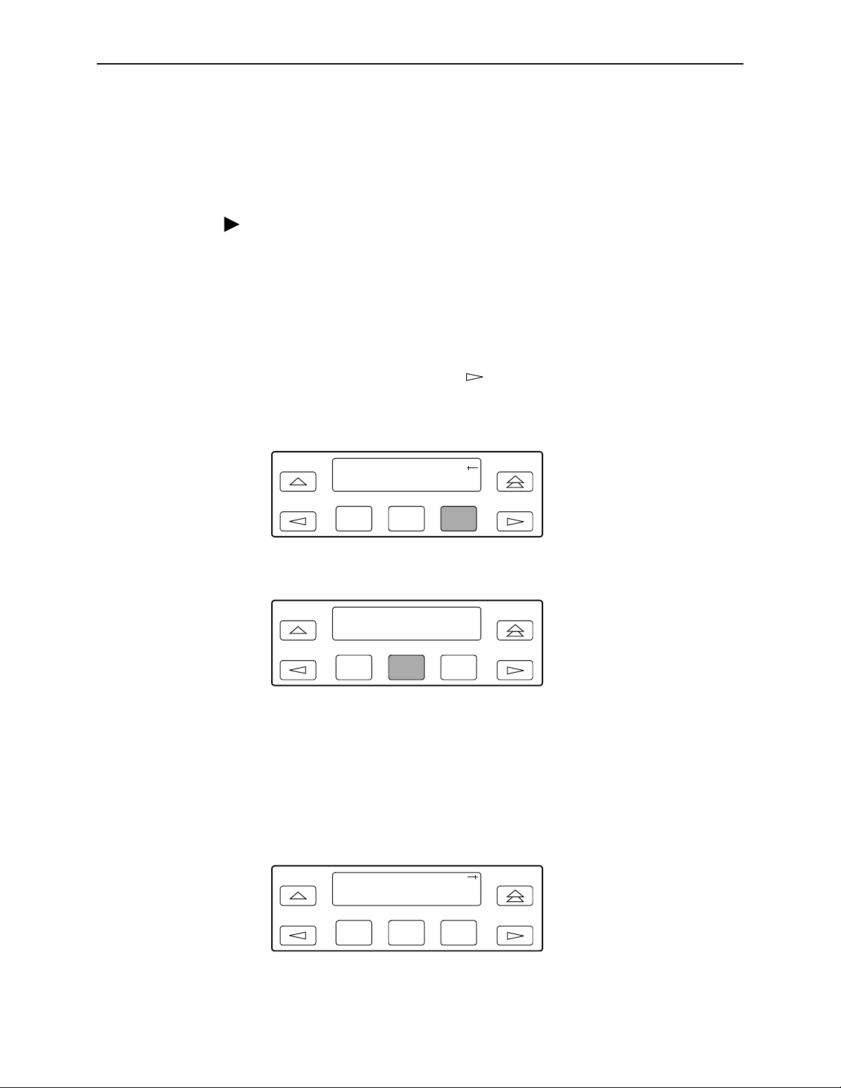
3. Operation
Configuring a Destination for SNMP Traps
A destination must be configured for each SNMP trap manager specified. This
configuration option is displayed for the number of trap managers specified by the
Number of Trap Managers configuration option.
Procedure
To configure an IP address for the SNMP trap manager:
1. From the top-level menu screen, select Cnfig.
2. Select the configuration option set to be copied into the Edit area by using the
appropriate Function key. Use the scroll keys, if necessary.
3. Select Edit.
4. From the Edit screen, press the key until the Mgmt selection appears on
the screen.
5. Select Mgmt.
Edit:
User Alarm Mgmt
F1
F2 F3
6. From the Mgmt Config screen, select Trap.
Mgmt Config:
Gen Trap
F1
7. Press F1 (Next) until the Trap
F2 F3
n
IP Address configuration option appears.
8. Press F2 (Edit) to edit the IP address. You have the option of using F3 (Clear)
to reset the IP address to the factory default
the IP Address
9. Press F1 (Next) until the Trap
on page 3-21 for more information on setting an IP address.
n
Destination configuration appears, and select
000.000.000.000
. Refe r to
Setting
the destination for the SNMP trap by using the appropriate Function key. Use
the scroll keys, if necessary.
Trapn Dst:
Next None Com
F1
February 2001 3160-A2-GB21-90
3-28
F2 F3
Page 63

Configuring DS0 Channels
The DSU/CSU provides channel configuration options that allow you to do the
following:
Display the DS0 assignments for the network, DTE Drop/Insert (DSX-1), and
data port interfaces.
Allocate DS0 channels on the DTE Drop/Insert (DSX-1) interface to the
network interface.
Allocate DS0 channels on the network or DTE Drop/Insert (DSX-1) interface to
particular data ports.
Clear (deallocate) all DS0 channels from the network, DTE Drop/Insert
(DSX-1), or data port interface.
Map data from one port to another.
To allocate DS0 channels, begin by defining the logical channel configuration for
the network interface, and then the DTE Drop/Insert (DSX-1) interface, and then
any ports, if desired. See Figure 3-6, Example of Channel Allocation, for an
example of a conceptual diagram of a channel configuration.
3. Operation
Blank configuration worksheets are provided at the back of Appendix C,
Configuration Options
allocation:
1. Complete the Network Interface and the DTE Drop/Insert (DSX-1) Interface
tables (unless the DTE Drop/Insert interface is disabled) as shown in the
examples in Figure 3-7, Example of Interface Worksheet for Network Interface,
and Figure 3-8, Example of Interface Worksheet for DTE Drop/Insert Interface.
2. Complete the Robbed Bit Signaling (RBS) information worksheet as shown in
the examples in Figure 3-9, Example of RBS Information Worksheet.
3. Using the worksheets shown in Figure 3-10, Port Channel Configuration
Worksheet (Ports 1 and 2), and Figure 3-11, Port Channel Configuration
Worksheet (Ports 3 and 4), circle the configuration options needed to
implement the logical channel configuration.
Once you have completed the worksheets, enter this information using the
procedures in
Allocating Data Ports
. To complete the configuration worksheets for DS0 channel
on page 3-38.
3160-A2-GB21-90 February 2001
3-29
Page 64

3. Operation
NETWORK
INTERFACE
N1
N2
N3
N4
N5
N6
N7
N8
N9
N10
N11
N12
N13
N14
N15
N16
N17
N18
N19
N20
N21
N22
N23
N24
DTE DROP/INSERT
(DSX-1) INTERFACE
D1
D2
D3
D4
D5
D6
D7
D8
D9
D10
D11
D12
D13
D14
D15
D16
D17
D18
D19
D20
D21
D22
D23
D24
PORTS
PRT 1
PRT 2
PRT 3
PRT 4
496-14907-01
Figure 3-6. Example of Channel Allocation
February 2001 3160-A2-GB21-90
3-30
Page 65

Network Interface
Network Channel Allocation
3. Operation
N1
N2
N3
N4
N5
N6
N7
N8
N9
N10
N11
N12
N13
N14
N15
N16
D1
D2
D3
D4
D5
D9
D10
D11
D12
D15
Prt1
Prt1
Prt1
N17
N18
N19
N20
N21
N22
N23
N24
Allocations:
D24 indicates allocation to DTE Drop/Insert (DSX-1) channels.
D1
–
Prt1
Prt4 indicates allocation to synchronous data ports.
–
Prt3
Prt2
Prt2
Prt2
Prt2
Prt2
Prt2
Prt3
Figure 3-7. Example of Interface Worksheet for Network Interface
3160-A2-GB21-90 February 2001
3-31
Page 66

3. Operation
DTE Drop/Insert (DSX-1) Interface
DTE (DSX-1) Channel Allocation
D1
D2
D3
D4
D5
D6
D7
D8
D9
D10
D11
D12
D13
D14
D15
D16
N1
N2
N3
N4
N5
N9
N10
N11
N12
N13
D17
D18
D19
D20
D21
D22
D23
D24
Allocations:
N24 indicates allocation to network channels.
N1
–
Figure 3-8. Example of Interface Worksheet for DTE Drop/Insert Interface
February 2001 3160-A2-GB21-90
3-32
Page 67

3. Operation
DTE Chan Config Assign: (N1
D1
D2
D3
D4
D5
D6
D7
D8
D9
D10
D11
D12
D13
D14
D15
N1 RBS
N2 RBS
N3 RBS
N4 RBS
N5 Data
N9 RBS
N10 RBS
N11 Data
N12 Data
N13 Data
24) Voice (RBS or Data)
–
D16
D17
D18
D19
D20
D21
D22
D23
D24
Figure 3-9. Example of RBS Information Worksheet
3160-A2-GB21-90 February 2001
3-33
Page 68

3. Operation
Port Cha n
Conf Options Value
Assign To NET, DTE, Prt2, Prt3, Prt4
Assign By Block, ACAMI, Chan
Port Rate Nx64: 64, 128, 192, 256, 320, 384, 448, 512, 576, 640, 704,
768, 832, 896, 9 60, 10 24 , 1088, 1152, 1216, 1280, 13 44, 1408,
1472, 1536
Nx56: 56, 112, 168, 224, 280, 336, 392, 448, 504, 560, 616,
672, 728, 784, 840, 896, 952, 1008, 1064, 1120, 1176, 1232,
1288, 1344
15, 16, 17, 18, 19, 20, 21, 22, 23, 24
(Select One)
Nx56: 56, 112, 168, 2 24, 280 , 336, 3 92, 448 , 504, 560, 61 6, 672
15, 16, 17, 18, 19, 20, 21, 22, 23
(Select One)
Port 1
If Assign By Block
If Assign By ACAMI
Start At Time Slot (N
Port Rate Nx64: 64, 1 28, 192 , 256, 320, 38 4, 448, 512, 5 76, 640 , 704, 7 68
Start At Time Slot (Nx or Dx): 1, 2, 3, 4, 5, 6, 7, 8, 9, 10, 11, 12, 13, 14,
x
or Dx): 1, 2, 3, 4, 5, 6, 7, 8, 9, 10, 11, 12, 13, 14,
Port 2
Time Slot (Nx or Dx): 1, 2, 3, 4, 5, 6, 7, 8, 9, 10, 11, 12, 13, 14,
If Assign By Chan
Assign To NET, DTE, Prt1, Prt3, Prt4
Assign By Block, ACAMI, Chan
Port Rate Nx64: 64, 128, 192, 256, 320, 384, 448, 512, 576, 640, 704,
If Assign By Block
Start At Time Slot (N
Port Rate Nx64: 64, 1 28, 192 , 256, 320, 38 4, 448, 512, 5 76, 640 , 704, 7 68
If Assign By ACAMI
If Assign By Chan
Start At Time Slot (N
15, 16, 17, 18, 19, 20, 21, 22, 23, 24
(Select Multiple)
768, 832, 896, 9 60, 10 24 , 1088, 1152, 1216, 1280, 13 44, 1408,
1472, 1536
Nx56: 56, 112, 168, 224, 280, 336, 392, 448, 504, 560, 616,
672, 728, 784, 840, 896, 952, 1008, 1064, 1120, 1176, 1232,
1288, 1344
x
or Dx): 1, 2, 3, 4, 5, 6, 7, 8, 9, 10, 11, 12, 13, 14,
15, 16, 17, 18, 19, 20, 21, 22, 23, 24
(Select One)
Nx56: 56, 112, 168, 2 24, 280 , 336, 3 92, 448 , 504, 560, 61 6, 672
x
or Dx): 1, 2, 3, 4, 5, 6, 7, 8, 9, 10, 11, 12, 13, 14,
15, 16, 17, 18, 19, 20, 21, 22, 23
(Select One)
Time Slot (N
15, 16, 17, 18, 19, 20, 21, 22, 23, 24
(Select Multiple)
x
or Dx): 1, 2, 3, 4, 5, 6, 7, 8, 9, 10, 11, 12, 13, 14,
Figure 3-10. Port Channel Configuration Worksheet (Ports 1 and 2)
February 2001 3160-A2-GB21-90
3-34
Page 69

Port Cha n
Conf Options Value
Assign To NET, DTE, Prt1, Prt2, Prt4
Assign By Block, ACAMI, Chan
Port Rate Nx64: 64, 128, 192, 256, 320, 384, 448, 512, 576, 640, 704,
768, 832, 896, 9 60, 10 24 , 1088, 1152, 1216, 1280, 13 44, 1408,
1472, 1536
Nx56: 56, 112, 168, 224, 280, 336, 392, 448, 504, 560, 616,
672, 728, 784, 840, 896, 952, 1008, 1064, 1120, 1176, 1232,
1288, 1344
15, 16, 17, 18, 19, 20, 21, 22, 23, 24
(Select One)
Nx56: 56, 112, 168, 2 24, 280 , 336, 3 92, 448 , 504, 560, 61 6, 672
15, 16, 17, 18, 19, 20, 21, 22, 23
(Select One)
Port 3
If Assign By Block
If Assign By ACAMI
Start At Time Slot (N
Port Rate Nx64: 64, 1 28, 192 , 256, 320, 38 4, 448, 512, 5 76, 640 , 704, 7 68
Start At Time Slot (Nx or Dx): 1, 2, 3, 4, 5, 6, 7, 8, 9, 10, 11, 12, 13, 14,
3. Operation
x
or Dx): 1, 2, 3, 4, 5, 6, 7, 8, 9, 10, 11, 12, 13, 14,
Port 4
Time Slot (Nx or Dx): 1, 2, 3, 4, 5, 6, 7, 8, 9, 10, 11, 12, 13, 14,
If Assign By Chan
Assign To NET, DTE, Prt1, Prt2, Prt3
Assign By Block, ACAMI, Chan
Port Rate Nx64: 64, 128, 192, 256, 320, 384, 448, 512, 576, 640, 704,
If Assign By Block
Start At Time Slot (N
Port Rate Nx64: 64, 1 28, 192 , 256, 320, 38 4, 448, 512, 5 76, 640 , 704, 7 68
If Assign By ACAMI
If Assign By Chan
Start At Time Slot (N
15, 16, 17, 18, 19, 20, 21, 22, 23, 24
(Select Multiple)
768, 832, 896, 9 60, 10 24 , 1088, 1152, 1216, 1280, 13 44, 1408,
1472, 1536
Nx56: 56, 112, 168, 224, 280, 336, 392, 448, 504, 560, 616,
672, 728, 784, 840, 896, 952, 1008, 1064, 1120, 1176, 1232,
1288, 1344
x
or Dx): 1, 2, 3, 4, 5, 6, 7, 8, 9, 10, 11, 12, 13, 14,
15, 16, 17, 18, 19, 20, 21, 22, 23, 24
(Select One)
Nx56: 56, 112, 168, 2 24, 280 , 336, 3 92, 448 , 504, 560, 61 6, 672
x
or Dx): 1, 2, 3, 4, 5, 6, 7, 8, 9, 10, 11, 12, 13, 14,
15, 16, 17, 18, 19, 20, 21, 22, 23
(Select One)
Time Slot (N
15, 16, 17, 18, 19, 20, 21, 22, 23, 24
(Select Multiple)
x
or Dx): 1, 2, 3, 4, 5, 6, 7, 8, 9, 10, 11, 12, 13, 14,
Figure 3-11. Port Channel Configuration Worksheet (Ports 3 and 4)
3160-A2-GB21-90 February 2001
3-35
Page 70

3. Operation
NOTE:
The following procedures are examples only.
depending on the model and configuration of the DSU/CSU .
Displaying DS0 Channel Assignments
Use the Display command (in the Channel Configuration branch) to view how the
DS0 channels are currently allocated.
Line 1 of the display shows the 24 channels of the selected interface. Pressing the
or key scrolls the channels onto the screen in groups of three. Line 2
displays what is allocated to the DS0 channel listed in Line 1. Symbols used in the
display are shown in Table 3-5, Display Channel Symbols.
Table 3-5. Display Channel Symbols
Symbol Meaning
– The DS0 channel is not allocated.
Prt
n
n
N
D
n
The DS0 channel is allocated to Port n, where n is 1, 2, 3, or 4.
The DS0 channel is allocated to the network interface DS0 channel n,
where n can be any number from 1 through 24.
The DS0 channel is allocated to the DTE Drop/Insert (DSX-1) interface
DS0 channel n, where n can be any number from 1 through 24.
Screen displays may vary
Procedure
To display the DS0 channel allocation:
1. From the top-level menu screen, select Cnfig.
2. Select the configuration option set to be copied into the Edit area by using the
appropriate Function key. Use the scroll keys, if necessary.
3. Select Edit.
4. From the Edit screen, press the key until the Chan selection appears on
the screen.
5. Select Chan.
Edit:
Port NET Chan
F1
F2
F3
February 2001 3160-A2-GB21-90
3-36
Page 71

6. From the Channel Config screen, select Dsply.
Channel Config:
Dsply Clear DTE
3. Operation
F1
F2 F3
7. From the Display Chan screen, select NET to display the channels allocated to
the network interface. Or, select DTE to display the channels allocated to the
DTE Drop/Insert (DSX-1) interface.
Display Chan:
NET DTE Ports
F1
F2
F3
8. If you selected NET the channels allocated to the network interface are
displayed. Line 1 displays the 24 channels for the network interface, while Line
2 displays what is allocated to the DS0 channel shown in Line 1. Pressing the
or key scrolls the channels onto the screen in groups of three.
N1 N2 N3
D2 D3 Prt1
F1
F2
F3
If you selected DTE, the channels allocated to the DTE Drop/Insert (DSX-1)
interface are displayed. Line 1 displays the 24 channels for the DTE
Drop/Insert (DSX-1) interface, while Line 2 displays what is allocated to the
DS0 channel shown in Line 1.
D1 D2 D3
– N1 N2
F1
F2 F3
3160-A2-GB21-90 February 2001
3-37
Page 72

3. Operation
Allocating Data Ports
By using the configuration options, assign a specific port to DS0 channels on
either the network interface or the DTE Drop/Insert (DSX-1) interface. The
following methods are available to assign DS0 channels to the port:
Block
– Allows a block of contiguous channels to be assigned by specifying a
data port rate and an initial DS0 channel (the first DS0 channel in a block of
DS0 channels). The number of channels assigned is determined by the port
rate. Only those initial DS0 channel numbers that provide enough bandwidth
(based on the port’s data rate) are displayed on the screen. These channels
are automatically assigned to the destination T1 interface (Network or DTE
Drop/Insert) when the initial DS0 channel is selected.
ACAMI (Alternate Channel Alternate Block Inversion)
– Allows a block of
contiguous channels to be assigned by specifying a data port rate and an
initial DS0 channel (the first DS0 channel in a block of DS0 channels).
However, with ACAMI, the number of channels assigned is twice the number
needed for the port rate. This is because with ACAMI, every alternate DS0
channel (starting with the
n
+1 DS0 channel), does not carry data from the
port, but instead always transmits and receives all ones.
Chan (Channel)
– Individually selects the DS0 channels to allocate to the
data port. The data port rate is automatically determined based on the number
of channels selected.
Once a port is selected, you have access to the configuration options to complete
the port allocation procedure. These configuration options enable you to,
Assign the selected port to the desired interface.
Select the desired method for channel allocation.
Select the port rate and starting channel (if the allocation method is block or
ACAMI).
Select the specific channels (if the allocation method is by individual channel).
February 2001 3160-A2-GB21-90
3-38
Page 73

3. Operation
Procedure
To select the data port:
1. From the top-level menu screen, select Cnfig.
2. Select the configuration option set to be copied into the Edit area by using the
appropriate Function key. Use the scroll keys, if necessary.
3. Select Edit.
4. From the Edit screen, press the key until the Chan selection appears on
the screen.
5. Select Chan.
Edit:DTE
Port NET Chan
F1
F2 F3
6. From the Channel Config screen, press the key to scroll the ports onto the
screen.
7. Select the desired port by pressing its corresponding Function key.
Channel Config:
Prt1 Prt2 Prt3
F1
F2 F3
8. The configuration option for the data port channel allocation destination
appears on the screen. Select NET to assign this port to the network interface,
select DTE to assign this port to the DTE Drop/Insert (DSX-1) interface, or
press the key and the appropriate Function key to assign this port to
another port.
Assign To:NET
Next NET DTE
F1
F2
9. Press F1 (Next) to display the appropriate configuration options on the screen.
Use one of the following examples, depending on whether you are assigning
by block, ACAMI, or individual channel.
3160-A2-GB21-90 February 2001
F3
3-39
Page 74
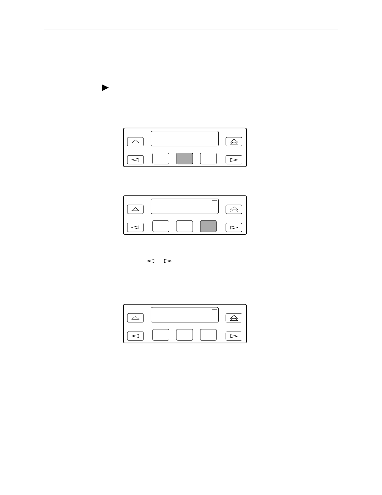
3. Operation
Block or ACAMI Assignment Method
The Assign By configuration option screen appears after you select a port.
Procedure
To assign by the block or ACAMI method:
1. Press F2 for Block or F3 for ACAMI.
Assign By:
Next Block ACAMI
F1
F2 F3
or
Assign By:
Next Block ACAMI
F1
F2
F3
2. Press F1 (Next) to display the next configuration option (Port Rate).
3. Use the or key to scroll the desired port rate onto the screen. Rates
scroll in groups of three. Available selections depend on the current base rate
selected for the port. Press the corresponding Function key to select the port
rate. Then, select Next to display the Start At configuration option on the
screen.
Port Rate:384
Next 64 128
F1
F2
F3
NOTE:
For port-to-port mapping, the procedure is complete after the port rate is
selected.
February 2001 3160-A2-GB21-90
3-40
Page 75

3. Operation
4. The Start At screen displays the configuration option used to select the
starting DS0 channel. If the destination selected is the network interface, then
the network channels appear on the screen. If the destination selected is the
DTE Drop/Insert (DSX-1) interface, then these channels appear on the
screen.
The following screen shows an example for the network interface. Use the
or key to scroll the desired channel onto the screen. Use the Function keys
to select the starting channel. Only those DS0 channel numbers that provide
enough bandwidth (based on the configured data rate) to be used as a starting
channel number are displayed. Channel allocation for this port can only be
cleared by selecting Clear.
Start At:Clear
Next Clear N1
F1
Individual Channel Assignment Method
The Assign By configuration option screen appears after you select a port.
Procedure
To assign by the individual channel method:
1. Press the key once to bring the Chan selection onto the screen.
Assign By:Block
Next Block ACAMI
F1
2. Press F3 (Chan).
Assign By:Chan
Block ACAMI Chan
F2 F3
F2 F3
F1
F2 F3
3. Press F1 (Next) to display the next configuration option (channel allocation).
3160-A2-GB21-90 February 2001
3-41
Page 76

3. Operation
4. Line 1 displays the 24 channels for the network interface or the DTE
Drop/Insert (DSX-1) interface, depending on which destination was chosen.
This example assumes that the network is the destination. Line 2 displays
what is allocated to the DS0 channel shown in Line 1. Pressing the or
key scrolls the channels onto the screen in groups of three. Select the channel
by pressing the Function key under the desired number. Port
n
appears. The
port is assigned to that channel. To deallocate a port, press the Function key
under that port number. Pressing the Function key under channels assigned to
other ports has no effect.
N1 N2
Next Prt1 Prt2
F1
F2
F3
Allocating DS0 Channels from the DTE Drop/Insert Interface to the Network Interface
By using the configuration options, you can allocate DS0 channels from the DTE
Drop/Insert (DSX-1) interface to the network interface and specify which DS0
channels carry Robbed Bit Signaling (RBS) information for voice channels.
Procedure
To allocate DS0 channels from the DTE Drop/Insert (DSX-1) interface to the
network interface:
1. From the top-level menu screen, select Cnfig.
2. Select the configuration option set to be copied into the Edit area by using the
appropriate Function key. Use the scroll keys, if necessary.
3. Select Edit.
4. From the Edit screen, press the key until the Chan selection appears on
the screen.
5. Select Chan.
Edit:
Port NET Chan
F1
F2 F3
6. From the Channel Config screen, select DTE.
Channel Config:
Dsply Clear DTE
F1
February 2001 3160-A2-GB21-90
3-42
F2
F3
Page 77

7. From the DTE Channels screen, press F1 to select Assign.
DTE Channels:
Assign Voice
3. Operation
F1
F2 F3
8. Press the Function key below the network channel desired. Each time that you
press the Function key, the DTE channel number will scroll up one number. If
the network channel is currently unassigned (‘‘–” is displayed on Line 2), the
DTE channel number initially displays the same number as the corresponding
network channel number. However, if the network channel is currently
assigned, the DTE channel number is shown as D
n.
Pressing the Function key
for D24 wraps the display back to D1. Only those channels that are not already
assigned will appear on the LCD when scrolling. The network channels
assigned to ports (Prt1...Prt4) are unavailable for assignment.
N1 N2 N3
D1 D2 –
F1
F2
F3
Procedure
To specify DTE Drop/Insert (DSX-1) channels used to carry voice information,
1. Press from the channel allocation screen to return to the DTE Channels
screen.
N1 N2 N3
D1 D2 –
F1
F2 F3
2. From the DTE Channels screen, press F2 to select Voice.
DTE Channels:
Assign Voice
F1
F2 F3
3160-A2-GB21-90 February 2001
3-43
Page 78

3. Operation
3. Line 1 displays the 24 DS0 channels for the DTE Drop/Insert (DSX-1)
interface. Pressing the or key scrolls the channels onto the screen in
groups of three. Line 2 displays whether the DS0 channel in Line 1 is a data
channel (Data) or a voice (RBS) channel. Each time that you press the
Function key located below the desired channel, the display in Line 2 toggles
between Data and RBS.
D1 D2 D3
RBS RBS RBS
Clearing DS0 Channel Allocation
You can clear (deallocate) all the DS0 channels currently allocated to either the
network interface, the DTE Drop/Insert (DSX-1) interface, or the synchronous data
ports.
Procedure
To clear DS0 channel allocation:
1. From the top-level menu screen, select Cnfig.
2. Select the configuration option set to be copied into the Edit area by using the
appropriate Function key. Use the scroll keys, if necessary.
3. Select Edit.
4. From the Edit screen, press the key until the Chan selection appears on
the screen.
5. Select Chan.
F1
F2 F3
Edit:
Port NET Chan
F1
F2
F3
6. From the Channel Config screen, select Clear.
Channel Config:
Dsply Clear DTE
F1
February 2001 3160-A2-GB21-90
3-44
F2
F3
Page 79

3. Operation
7. From the Clear Channel screen, select NET to clear all DS0 channels
assigned to the network interface. Or, select DTE to clear all DS0 channels
assigned to the DTE Drop/Insert (DSX-1) interface. Or, select a port to clear all
assignments for that data port.
Clear Channel:
NET DTE Port1
F1
Providing Backup Capability
If the T1 network fails, the DSU/CSU provides the ability to reconfigure the unit
and restore (at least partially) priority data circuits through an external backup
device.
You can store backup configuration options in the Customer 2 set of
customer-defined configuration options. The Enterprise MIB variable
devConfigAreaCopy allows the entire contents of one configuration area to be
copied into another configuration area via SNMP.
By cross-connecting two synchronous data ports to each other, one port can
provide a backup path for the other. As soon as the ports are configured to be
mapped to each other, Data Set Ready (DSR) for the ports is turned on. The
external backup device can be configured to initiate dialing when it detects the
off-to-on transition of DSR.
Selecting the Timing Source
The DSU/CSU provides the ability to select a master clock (timing) source that is
used to synchronize all of the T1 and data port interfaces on the DSU/CSU. The
clock for each interface is at the appropriate rate for that interface
(e.g., 1.544 Mbps for the T1 interfaces, the configured port rate for the data ports),
and it is independent of the master clock rate. This means that the master clock
rate and the DSU/CSU interface rates may be different.
F2
F3
The clock source configuration options enable you to select either the network
interface, a synchronous data port, the internal clock, the DTE Drop/Insert
(DSX-1) interface, or an external clock. If external clocking is selected, you must
use the clock rate configuration option to specify the clock rate. Figure 3-12,
Common Clocking Configurations, shows some common clocking configurations.
Two sample procedures for configuring timing are given in the following sections,
Configuring for Network Timing
on page 3-47. For more information on configuration options, refer to Appendix C,
Configuration Options
3160-A2-GB21-90 February 2001
.
on page 3-47 and
Configuring for External Timing
3-45
Page 80

3. Operation
NOTE:
The external clock source is only available for 2-port and 4-port DSU/CSUs.
For carrier-mounted DSU/CSUs, the external clock provides timing for up to
eight slots in the carrier. Each Auxiliary Backplane must have its own external
clock input.
NETWORK
CLOCK: NETWORK CLOCK: NETWORK
CLOCK: NETWORKCLOCK: INTERNAL
CLOCK: EXTERNAL CLOCK: NETWORK
PBX
CLOCK: DTE (G.703) CONNECTOR
TERMINAL
EQUIPMENT
CLOCK: PORT 1, 2, 3, OR 4
Figure 3-12. Common Clocking Configurations
CLOCK: NETWORK
CLOCK: NETWORK
496-14341-03
February 2001 3160-A2-GB21-90
3-46
Page 81

Configuring for Network Timing
Procedure
To configure for network timing:
1. From the top-level menu screen, select Cnfig.
2. Select the configuration option set to be copied into the Edit area by using the
appropriate Function key. Use the scroll keys, if necessary.
3. Select Edit.
4. From the Edit screen, press the key until the Gen selection appears on the
screen.
5. Select Gen.
3. Operation
Edit:
NET Chan Gen
6. Press F1 (Next) to display the next configuration option (Clock Src).
7. Select the master clock source. For network, press F2 (note that network is
also the default).
Configuring for External Timing
Procedure
To configure 2-port and 4-port DSU/CSUs for external timing:
1. From the top-level menu screen, select Cnfig.
2. Select the configuration option set to be copied into the Edit area by using the
appropriate Function key. Use the scroll keys, if necessary.
F1
Clock Src:NET
Next NET DTE
F1
F2 F3
F2 F3
3. Select Edit.
4. From the Edit screen, press the key until the Gen selection appears on the
screen.
3160-A2-GB21-90 February 2001
3-47
Page 82

3. Operation
5. Select Gen.
Edit:
NET Chan Gen
F1
F2 F3
6. Press F1 (Next) to display the next configuration option (Clock Src).
7. Select the master clock source. For external, press the key until the Ext
selection appears on the screen.
8. Select Ext (external timing).
Clock Src:Ext
Prt1 Int Ext
F1
F2
F3
9. Select the appropriate external clock rate by pressing the corresponding
Function key. This step is mandatory if you have chosen external clocking.
Clock Rate:1544
Next 2048 1544
F1
F2 F3
Establishing Access Security on a Port
Although the password feature is available, it is not required as a factory default. If
used, it ensures access security before device control is passed to a device
connected to a port. The password configuration option can be individually set for
the COM or MODEM port, or both if security is needed on both port types. The
default is
section,
Procedure
To establish access security on a port:
1. From the top-level menu screen, select Cnfig.
2. Select the configuration option set to be copied into the Edit area by using the
3. Select Edit.
4. From the Edit screen, press the key until the User selection appears on the
February 2001 3160-A2-GB21-90
3-48
None.
Setting a Password
The password itself is set separately (refer to the following
on page 3-49).
appropriate Function key. Use the scroll keys, if necessary.
screen.
Page 83

5. Select User.
3. Operation
Edit:
Chan Gen User
6. Press F1 (Next) until the Password configuration option appears.
7. Select port(s) to receive access security (None, Com, Modem, or Both). Use
Setting a Password
In addition to establishing access security on a port (refer to the previous section,
Establishing Access Security on a Port
Unless you specify otherwise, the password is null.
Procedure
F1
F2 F3
the scroll keys, if necessary.
Password:None
Next None Com
F1
F2 F3
on page 3-48) the password itself is set.
To set a password:
1. From the top-level menu screen, press the key until the Ctrl selection
appears on the screen.
2. Select Ctrl.
3. From the Control screen, press the key until the Passwd selection appears
on the screen.
4. Select Passwd.
Control:
Reset CID Passwd
F1
F2
F3
3160-A2-GB21-90 February 2001
3-49
Page 84

3. Operation
5. Use the and keys to position the cursor under the desired character.
You must enter a character before the moves the cursor to the next space
to the right.
F1
xxxxxxxx
F2
Passwd:
Up Down Save
6. Enter the desired password. Press F1 (Up) and F2 (Down) to scroll up and
down through the valid characters/numbers for the password. Valid password
characters are
0-9, a-z, A-Z, #, -, .,
password.
F1
xxxxxxxx
F2 F3
Passwd:
Up Down Save
Entering a Password to Gain Access
You are prompted to enter a password (up to 8 characters) when you are
accessing a port whose Password configuration option is set (refer to the previous
section,
Setting a Password
on page 3-49).
F3
and/. Press F3 (Save) to save the
V al id p assword char ac ter s ar e
0-9, a-z, A-Z, #, -, .,
and /. The existing password is
not shown on the screen. An underscore in the first position shows where to enter
the first character. If the password is set to all null characters (default value), press
F3 (Done) when the password screen first appears.
The following screen appears when you access a DSU/CSU that has a password
enabled.
Passwd:_
Up Down Done
F1
F2
F3
February 2001 3160-A2-GB21-90
3-50
Page 85

3. Operation
Procedure
To enter a password:
1. Use the and keys to position the cursor under the desired character.
You must enter a character before the key moves the cursor to the next
space to the right. The key is not destructive.
Passwd:
Up Down Done
F1
xxxxxxxx
F2 F3
2. Enter the required password. Press F1 (Up) and F2 (Down) to scroll up and
down through the valid characters/numbers for the password. You have five
minutes to enter the correct password before the DSU/CSU ends the session.
3. Press F3 (Done) to indicate you are done entering the password. If you enter
an invalid password, the message
Acquiring/Releasing the User Interface
You can access the user interface from either the front panel, the COM port, the
MODEM port (for standalone DSU/CSUs), or the SDCP (for carrier-mounted
DSU/CSUs). The DSU/CSU allows only one user interface to be active at a time.
The front panel is the default user interface at power-up or after a reset. It is also
the default during a software download or when a failure occurs at either the local
or remote PC interface.
You can switch an inactive user interface to active if:
The current active user interface has had no activity (no key was pressed) for
at least five minutes.
Invalid Password
appears.
The active user interface has been released with the Release command.
The active interface connection is broken. This includes the call disconnect for
a modem interface or the termination of the front panel emulation program on
a locally-attached PC (if the PC supports DTR) or the termination of the async
terminal interface on a remote or locally attached terminal.
3160-A2-GB21-90 February 2001
3-51
Page 86

3. Operation
Acquiring the Active User Interface
To acquire the active user interface, press any key. If you are using the PC
interface, use the mouse to click on the desired Function key.
The top-level menu screen appears on the active user interface, regardless of
what screen was displayed at the previous a ctive user interface.
DSU ESF
Stat Test Cnfig
F1
F2
F3
The inactive interface displays the following message when a Function key is
pressed or a connection is made on the inactive user interface and control cannot
be switched because the currently active interface is in use. On the screen, either
Ft. Panel (front panel), Com Port, Modem, or SDCP is displayed in the user
interface (
User I/F
DSU ESF
User I/F
F1
) field.
active
F2
F3
The inactive interface displays the following message after control has been
released from the previously active interface and another interface has not
become active.
DSU ESF
User I/F
F1
idle
F2
F3
February 2001 3160-A2-GB21-90
3-52
Page 87

Releasing the Active User Interface
To release the current active user interface, either allow five minutes to elapse
without pressing any key or use the Release command.
Procedure
To use the Rele ase com man d:
1. From the top-level menu screen, press the key until the Ctrl selection
appears on the screen.
2. Select Ctrl.
3. From the Control screen, select Rel (Release).
3. Operation
Control:
Call Rel LED
F1
F2
The active user interface is released. The message
F3
Released
appears. No
user interface is active until input is received from a user interface.
3160-A2-GB21-90 February 2001
3-53
Page 88

3. Operation
Enabling/Disabling the Front Panel
You can enable or disable the display of information on the front panel. This feature
is useful for ensuring that other users do not inadvertently change the device’s
configuration options while you are using an external device (e.g., a PC or async
terminal). The factory default is
NOTE:
If you disable the front panel, be sure not to alter the configuration options for
using an external device (e.g., a PC or async terminal). If this happens, you
lose the ability to communicate with the device. You will need to contact your
service representative.
Procedure
To enable or disable the front panel:
1. From the top-level menu screen, select Cnfig.
Enable
.
2. Select the configuration option set to be copied into the Edit area by using the
appropriate Function key. Use the scroll keys, if necessary.
3. Select Edit.
4. From the Edit screen, press the key until the User selection appears on
the screen.
5. Select User.
6. Press F1 (Next) until the FP Access configuration option appears.
7. Press F2 to enable the front panel or F3 to disable the front panel.
FP Access:
Next Enab Disab
F1
F2 F3
February 2001 3160-A2-GB21-90
3-54
Page 89

Using the Integral Modem in Standalone DSU/CSUs
The standalone DSU/CSU’s integral modem enables your DSU/CSU to
communicate with remote devices to display alarm messages or to function as the
user interface.
modem.
The Call command, available from the Control branch of the menu tree, provides
the following functions to initiate and terminate modem connections:
Pass
DSU/CSU’s front panel from your DSU/CSU’s front panel (or PC attached to
the COM port).
Dial
or PC. Sets up a semipermanent connection to route alarm messages to the
specified destination.
Disconnect
Change Directory
directories.
The carrier-mounted DSU/CSU does not have an integral
– Initiates a call through the integral modem to access a far-end
– Initiates a call through the integral modem to a printer, ASCII terminal,
– Disconnects an active modem connection.
– Allows entry of phone numbers into the internal phone
3. Operation
For additional information, refer to
Appendix C,
Configuration Options
Entering Numbers in the Phone Directories
The DSU/CSU has five general directories (1 through 5) and one alarm directory
(A). Use the general directories to store phone numbers for remote devices such
as standalone DSU/CSUs and ASCII printers. Use the alarm directory to store the
phone number of the primary ASCII terminal or printer you use to display or print
alarms. This function is not available for carrier-mounted DSU/CSUs because the
integral modem is not available for carrier-mounted DSU/CSUs.
Procedure
To enter or change numbers in the phone directories:
1. From the top-level menu screen, press the key until the Ctrl selection
appears on the screen.
2. Select Ctrl.
3. From the Control screen, select Call.
Control:
Call Rel LED
User Interface Configuration Options
.
in
F1
3160-A2-GB21-90 February 2001
F2
F3
3-55
Page 90

3. Operation
4. From the Call Setup screen, select ChDir.
Call Setup:
Pass Dial ChDir
F1
F2 F3
The Directory 1 displays first, along with its phone number if one has been
entered.
5. Press F1 (Next) to display the next directory (2, in this case). Press F2
(Previous) to display the previous directory (A, in this case). Directories
appear in order, 1 through 5 and then A.
1: xxxxxxxxxxxxxxxxx
Next Prev Edit
F1
F2
F3
6. Press F3 (Edit) to change the displayed directory’s phone number (phone
numbers can be up to 40 characters). If you select Edit, the Edit screen
appears.
1: xxxxxxxxxxxxxxxxx
Next Prev Edit
F1
F2 F3
7. Use the and keys to position the cursor under the digit(s) you want to
change. Press F1 to scroll up to a higher digit. Press F2 to scroll down to a
lower digit. The key inserts blanks (default characters) while the key
invokes the End Of Number (EON) character which terminates the dial string
and erases any characters to the right when you use the Save function.
See Table 3-6, Valid Phone Number Characters, for the set of valid characters
and rules that apply to entering phone numbers.
Example: P9W8135551212
8. Press F3 (Save) to store your changes in nonvolatile memory. If you press
or before saving the phone number you just changed, the previous
phone number remains in effect.
1: xxxxxxxxxxxxxxxxx
Up Down Save
F1
February 2001 3160-A2-GB21-90
3-56
F2
F3
Page 91

3. Operation
Table 3-6. Valid Phone Number Characters
Valid
Characters Meaning Restrictions
0 to 9 DTMF or pulse digits —
* # DTMF digits —
P Selects Pulse dialing Pulse or Tone must be specified,
otherwise Tone is the default. This mus t
be the first character in the string,
unless the first character is B. Then, it
must immediately follow the B.
T Selects Tone (DTMF) dialing Tone or Pulse must be specified,
otherwise Tone is the default. This mus t
be the first character in the string,
unless the first character is B. Then, it
must immediately follow the B.
W Wait for dial tone —
B Blind dialing (you need not wait
for a dial tone before entering
the dialing sequence)
, Creates a 2-second pause in
the dialing sequence
<space> ( ) - Extra characters for readability.
The space is the default
character.
<- End Of Number (EON)
character, terminates the dial
string and erases all ch aracters
to the right after F3 (Save) is
pressed
Initiating a Call for Front Panel Pass-Through Operation
Front panel pass-through initiates a call through the integral modem to access a
far-end DSU/CSU’s front panel from your DSU/CSU’s front panel (or PC attached
to the COM port).
NOTE:
Pass is only available when the FP Pass configuration option has been
enabled (see Appendix C,
is either the front panel or the PC, and the integral modem is not already in
use.
Configuration Options
To be valid, this must be the first
character in the string.
—
—
—
), the acti ve ph ysical i nterface
3160-A2-GB21-90 February 2001
3-57
Page 92

3. Operation
Procedure
To initiate front panel pass-through at the near-end DSU/CSU:
1. From the top-level menu screen, press the key until the Ctrl selection
appears on the screen.
2. Select Ctrl.
3. From the Control screen, select Call.
Control:
Call Rel LED
F1
F2 F3
4. From the Call Setup screen, select Pass.
Call Setup:
Pass Dial ChDir
F1
F2 F3
5. From the Pass Directory screen, press F1 (Up) to display the next higher
numbered directory or press F2 (Down) to select the next lower numbered
directory.
Pass n:
Up Down Dial
F1
xxxxxxxxx
F2
F3
6. When the number of the desired directory appears on the screen, press F3
(Dial) to place the call.
Pass n:
xxxxxxxxx
Up Down Dial
F1
February 2001 3160-A2-GB21-90
3-58
F2 F3
Page 93

Initiating a Call for PC, ASCII Terminal/Printer, or SNMP Operation
Use the Dial command to set up a semipermanent connection to route alarm
messages to the specified destination. The Dial command initiates a call through
the integral modem to a printer, ASCII terminal, or PC.
Procedure
To initiate a call at the local DSU/CSU:
1. From the top-level menu screen, press the key until the Ctrl selection
appears on the screen.
2. Select Ctrl.
3. From the Control screen, select Call.
Control:
Call Rel LED
3. Operation
F1
F2
F3
4. From the Call Setup screen, select Dial. This selection is not available if the
DSU/CSU’s integral modem is already in use.
Call Setup:
Pass Dial ChDir
F1
F2 F3
5. From the Dial Directory screen, press F1 (Up) to display the next higher
numbered directory or press F2 (Down) to select the next lower numbered
directory.
Dial n:
xxxxxxxxx
Up Down Dial
F1
F2
F3
6. When the number of the desired directory appears on the screen, press F3
(Dial) to place the call.
Dial n:
xxxxxxxxx
Up Down Dial
F1
3160-A2-GB21-90 February 2001
F2 F3
3-59
Page 94

3. Operation
Disconnecting the Modem Connection
The Disconnect command enables you to force a disconnect of an active modem
connection from the front panel of the DSU/CSU. This command is only available
when the DSU/CSU modem is connected.
Disconnect methods include:
Using the Disconnect command via the front panel menu (for
all
dial
connections, or when a pass-through connection is established to another
316x DSU/CSU).
Pressing and holding the and front panel keys simultaneously (when a
pass-through connection is established to a remote device other than a
316x DSU/CSU).
Procedure
To disconnect an established modem connection using the Disconnect command:
1. From the top-level menu screen, press the key until the Ctrl selection
appears on the screen.
2. Select Ctrl.
3. From the Control screen, select Call.
Control:
Call Rel LED
F1
F2 F3
4. From the Call Setup screen, select Disc.
Call Setup:
Disc ChDir
F1
F2 F3
The modem call is disconnected and the Command Complete screen
appears.
Disconnect:
Command Complete
F1
February 2001 3160-A2-GB21-90
3-60
F2
F3
Page 95
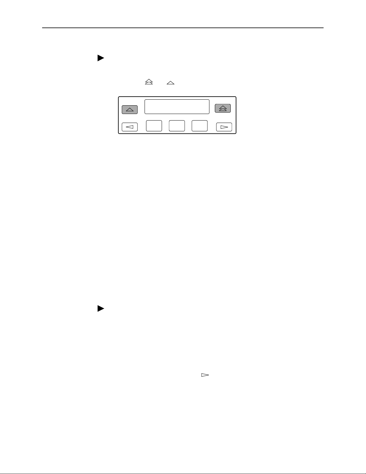
3. Operation
Procedure
To disconnect a modem connection using two front panel keys:
1. Press the and keys simultaneously and hold for two seconds.
Call Setup:
Disc ChDir
F1
F2
F3
The modem call is disconnected and the Command Complete screen
appears.
Enabling the Communication Port for Carrier-Mounted DSU/CSUs
Communication between the carrier-mounted DSU/CSUs and an external PC,
ASCII device, SNMP manager, or async terminal interface (attached either locally
or through an external modem) occurs through a shared communication (COM)
port. (For COM port cabling information, refer to the
Carrier Installation Manual
.) Unlike standalone DSU/CSUs, the carrier-mounted
DSU/CSUs do not have a dedicated COM port for external access. Once the COM
port is enabled, other COM port configuration options can be selected. These
options are used to configure Port 2 on the Auxiliary Backplane as a COM port for
the carrier.
NOTE:
If a Model 3161 DSU/CSU has the COM port enabled, Port 2 cannot be used
as a data port.
COMSPHERE 3000 Series
Procedure
To enable the COM port on the carrier-mounted DSU/CSU:
1. From the top-level menu screen, select Cnfig.
2. Select the configuration option set to be copied into the Edit area by using the
appropriate Function key. Use the scroll keys, if necessary.
3. Select Edit.
4. From the Edit screen, press the key until the User selection appears on the
screen.
3160-A2-GB21-90 February 2001
3-61
Page 96

3. Operation
5. Select User.
Edit:
Chan Gen User
F1
F2 F3
6. Press F1 (Next) until the Com Port configuration option appears.
7. Select Enab to enable the COM port for the carrier-mounted DSU/CSU.
Com Port:
Next Enab Disab
F1
F2 F3
The carrier COM port provides the following functionality:
If configured for ASCII, only one ASCII device may be used for the carrier. (If
two COM ports are configured for ASCII, neither will work.)
If configured for Mgmt, each device in the carrier can support an Mgmt COM
port; however, each Mgmt COM port must be connected to a different subnet.
To facilitate IP data routing, the device with the closest link to the SNMP
manager or Telnet client should be configured as the IP Bus Master.
If configured for either ASCII or Mgmt, the carrier COM port may be configured
to control an external device (e.g., modem, x.25 PAD) through the use of A T or
user-specified commands.
The set of valid characters for control of the carrier external COM port device is as
follows:
The numbers: 0–9
The lowercase letters: a–z
The uppercase letters: A–Z
The space (“ ”) character
The ASCII symbols (in ascending order, based on the ASCII code)
The End Of Line (EOL) symbol:
The caret (“^”) control character is used to select non-printable ASCII
←
characters. The caret “^” must be followed by one character which together
form the control sequence. Table 3-7, Control Sequence, defines all of the
available control sequences.
February 2001 3160-A2-GB21-90
3-62
Page 97

Table 3-7. Control Sequence
Sequence ASCII HEX
^A or ^a SOH 0x01
^B or ^b STX 0x02
^C or ^c ETX 0x03
^D or ^d EOT 0x04
^E or ^e ENQ 0x05
^F or ^f ACK 0x06
^G or ^g BEL 0x07
^H or ^h BS 0x08
^I or ^i HT 0x09
^J or ^j LF or NL 0x0A
^K or ^k VT 0x0B
3. Operation
^L or ^l FF or NP 0x0C
^M or ^m CR 0x0D
^N or ^n SO 0x0E
^O or ^o SI 0x0F
^P or ^p DLE 0x10
^Q or ^q DC1 0x11
^R or ^r DC2 0x12
^S or ^s DC3 0x13
^T or ^t DC4 0x14
^U or ^u NAK 0x15
^V or ^v SYN 0x16
^W or ^w ETB 0x17
^X or ^x CAN 0x18
^Y or ^y EM 0x19
^Z or ^z SUB 0x1A
^{ ESC 0x1B
^\ FS 0x1C
^} GS 0x1D
^^ RS 0x1E
^_ US 0x1F
3160-A2-GB21-90 February 2001
3-63
Page 98

3. Operation
Deactivating the Alarm Relay for Carrier-Mounted DSU/CSUs
The Alarm Cut-off command forces a deactivation of the alarm relay on the
3000 Series Carrier during an alarm condition. Since this function only affects the
3000 Series Carrier, it is only available for carrier-mounted DSU/CSUs. The alarm
relay function must first be enabled by the Alarm Relay configuration option (refer
to Appendix C,
Procedure
To deactivate the alarm relay:
1. From the top-level menu screen, press the key until the Ctrl selection
appears on the screen.
2. Select Ctrl.
3. From the Control screen, select ACO.
Configuration Options
Control:
ACO Rel LED
).
F1
F2
F3
4. The Command Complete screen appears.
Alarm Cut-Off:
Command Complete
F1
F2 F3
February 2001 3160-A2-GB21-90
3-64
Page 99

Resetting the DSU/CSU
Use the Reset command to perform a power-on reset of the DSU/CSU.
Procedure
To reset the DSU/CSU:
1. From the top-level menu screen, press the key until the Ctrl selection
appears on the screen.
2. Select Ctrl.
3. From the Control screen, press the key until the Reset selection appears
on the screen.
4. Select Reset.
3. Operation
Control:
ClrReg Reset
5. From the Device Reset screen, press F1 to initiate a reset of the DSU/CSU
(the power-up sequence screen appears). Press F2 instead to return to the
Control screen without init iating a reset.
Download Operations
NOTE:
The Download command is for use by service personnel only. Loss of primary
data could result from improper use.
F1
Device Reset:
Yes No
F1
F2
F2 F3
F3
3160-A2-GB21-90 February 2001
3-65
Page 100

3. Operation
February 2001 3160-A2-GB21-90
3-66
 Loading...