

Page 1

ACCULINK
3162 DSU/CSU
USER’S GUIDE
Document No. 3162-A2-GB20-30
March 1999
Page 2

Copyright 1999 Paradyne Corporation.
All rights reserved.
Printed in U.S.A.
Notice
This publication is protected by federal copyright law. No part of this publication may be copied or distributed,
transmitted, transcribed, stored in a retrieval system, or translated into any human or computer language in any form
or by any means, electronic, mechanical, magnetic, manual or otherwise, or disclosed to third parties without the
express written permission of Paradyne Corporation, 8545 126th Ave. N., Largo, FL 33773.
Paradyne Corporation makes no representation or warranties with respect to the contents hereof and specifically
disclaims any implied warranties of merchantability or fitness for a particular purpose. Further, Paradyne Corporation
reserves the right to revise this publication and to make changes from time to time in the contents hereof without
obligation of Paradyne Corporation to notify any person of such revision or changes.
Changes and enhancements to the product and to the information herein will be documented and issued as a new
release to this manual.
Warranty, Sales, Service, and Training Information
Contact your local sales representative, service representative, or distributor directly for any help needed. For
additional information concerning warranty , sales, service, repair, installation, documentation, training, distributor
locations, or Paradyne worldwide office locations, use one of the following methods:
Internet: Visit the Paradyne World Wide Web site at www.paradyne.com. (Be sure to register your warranty
there. Select
Telephone: Call our automated system to receive current information by fax or to speak with a company
representative.
— Within the U.S.A., call 1-800-870-2221
— Outside the U.S.A., call 1-727-530-2340
Service & Support → Warranty Registration
.)
Trademarks
All products and services mentioned herein are the trademarks, service marks, registered trademarks or registered
service marks of their respective owners.
Document Feedback
We welcome your comments and suggestions about this document. Please mail them to Technical Publications,
Paradyne Corporation, 8545 126th Ave. N., Largo, FL 33773, or send e-mail to userdoc@paradyne.com. Include
the number and title of this document in your correspondence. Please include your name and phone number if you
are willing to provide additional clarification.
Printed on recycled paper
A
March 1999
3162-A2-GB20-30
Page 3

Important Information
!
Important Safety Instructions
1. Read and follow all warning notices and instructions marked on the product or included in the manual.
2. This product is intended to be used with a 3-wire grounding type plug – a plug which has a grounding pin. This is
a safety feature. Equipment grounding is vital to ensure safe operation. Do not defeat the purpose of the
grounding type plug by modifying the plug or using an adapter.
Prior to installation, use an outlet tester or a voltmeter to check the ac receptacle for the presence of earth
ground. If the receptacle is not properly grounded, the installation must not continue until a qualified electrician
has corrected the problem.
If a 3-wire grounding type power source is not available, consult a qualified electrician to determine another
method of grounding the equipment.
3. Slots and openings in the cabinet are provided for ventilation. To ensure reliable operation of the product and to
protect it from overheating, these slots and openings must not be blocked or covered.
4. Do not allow anything to rest on the power cord and do not locate the product where persons will walk on the
power cord.
5. Do not attempt to service this product yourself, as opening or removing covers may expose you to dangerous
high voltage points or other risks. Refer all servicing to qualified service personnel.
6. General purpose cables are provided with this product. Special cables, which may be required by the regulatory
inspection authority for the installation site, are the responsibility of the customer.
7. When installed in the final configuration, the product must comply with the applicable Safety Standards and
regulatory requirements of the country in which it is installed. If necessary , consult with the appropriate regulatory
agencies and inspection authorities to ensure compliance.
8. A rare phenomenon can create a voltage potential between the earth grounds of two or more buildings. If
products installed in separate buildings are interconnected, the voltage potential may cause a hazardous
condition. Consult a qualified electrical consultant to determine whether or not this phenomenon exists and, if
necessary, implement corrective action prior to interconnecting the products.
9. Input power to the ac voltage configuration of this product must be provided by a UL-listed or CSA-certified power
source with a Class 2 or Limited Power Source (LPS) output.
10. This product contains a coin cell lithium battery that is only to be replaced at the factory . Caution: There is a
danger of explosion if the battery is incorrectly replaced. Replace only with the same type. Dispose of used
batteries according to the battery manufacturer’s instructions. Attention: Il y a danger d’explosion s’il y a
remplacement incorrect de la batterie. Remplacer uniquement avec une batterie du même type. Mettre au rebut
les batteries usagées conformément aux instructions du fabricant.
1 1.In addition, if the equipment is to be used with telecommunications circuits, take the following precautions:
— Never install telephone wiring during a lightning storm.
— Never install telephone jacks in wet locations unless the jack is specifically designed for wet locations.
— Never touch uninsulated telephone wires or terminals unless the telephone line has been disconnected at the
network interface.
— Use caution when installing or modifying telephone lines.
— Avoid using a telephone (other than a cordless type) during an electrical storm. There may be a remote risk of
electric shock from lightning.
— Do not use the telephone to report a gas leak in the vicinity of the leak.
3162-A2-GB20-30 March 1999
B
Page 4

Important Information
EMI Warnings
!
WARNING:
This equipment has been tested and found to comply with the limits for a Class A digital device,
pursuant to Part 15 of the FCC rules. These limits are designed to provide reasonable protection against
harmful interference when the equipment is operated in a commercial environment. This equipment
generates, uses, and can radiate radio frequency energy and, if not installed and used in accordance
with the instruction manual, may cause harmful interference to radio communications. Operation of this
equipment in a residential area is likely to cause harmful interference in which case the user will be
required to correct the interference at his own expense.
The authority to operate this equipment is conditioned by the requirements that no modifications will be
made to the equipment unless the changes or modifications are expressly approved by Paradyne
Corporation.
!
WARNING:
To Users of Digital Apparatus in Canada:
This Class A digital apparatus meets all requirements of the Canadian interference-causing equipment
regulations.
Cet appareil numérique de la classe A respecte toutes les exigences du règlement sur le matérial
brouilleur du Canada.
C
March 1999
3162-A2-GB20-30
Page 5

Important Information
Government Requirements and Equipment Return
Certain governments require that instructions pertaining to CSU connection to the telephone network be included in
the installation and operation manual. Specific instructions are listed in the following sections.
United States
NOTICE TO USERS OF THE UNITED STATES TELEPHONE NETWORK
1. This equipment complies with Part 68 of the FCC rules. On the bottom of the DSU/CSU is a label that contains,
among other information, the FCC registration number. If requested, this information must be provided to the
telephone company .
2. The T1 network connection should be made using a Universal Service Order Code (USOC) type RJ48C jack. The
Service Order Code 6.0F should be specified to the telephone company when ordering the T1 line. In addition,
the proper Facility Interface Code must be specified to the telephone company . The DSU/CSU can be configured
to support any of the following framing format and line signaling techniques. The DSU/CSU configuration must
correspond to the T1 line’s parameters.
DSU/CSU Facility Interface Codes
Code Description
04DU9-BN 1.544 Mbps superframe format (SF) without line power
04DU9-DN 1.544 Mbps SF and B8ZS without line power
04DU9-1KN 1.544 Mbps ANSI ESF without line power
04DU-1SN 1.544 Mbps ANSI ESF and B8ZS without line power
3. An FCC compliant telephone cord and modular plug is provided with this equipment. This equipment is designed
to be connected to the telephone network or premises wiring using a compatible modular jack which is Part 68
compliant. See the installation instructions for details.
4. If the DSU/CSU causes harm to the telephone network, the telephone company will notify you in advance that
temporary discontinuance of service may be required. But if advance notice is not practical, the telephone
company will notify the customer as soon as possible. Also, you will be advised of your right to file a complaint
with the FCC if you believe it is necessary.
5. The telephone company may make changes in its facilities, equipment, operations, or procedures that could affect
the operation of the equipment. If this happens, the telephone company will provide advance notice in order for
you to make the necessary modifications in order to maintain uninterrupted service.
6. If you experience trouble with this equipment, please contact your sales or service representative (as appropriate)
for repair or warranty information. If the product needs to be returned to the company service center for repair,
contact them directly for return instructions using one of the following methods:
Via the Internet: Visit the Paradyne World Wide Web site at http://www.paradyne.com
Via Telephone: Call our automated call system to receive current information via fax or to speak with a
company representative.
— Within the U.S.A., call 1-800-870-2221
— Outside the U.S.A., call 727-530-2340
If the trouble is causing harm to the telephone network, the telephone company may request that you remove the
equipment from the network until the problem is resolved.
3162-A2-GB20-30 March 1999
D
Page 6

Important Information
7. If your DSU/CSU is in need of repair, refer to the
8. No repairs may be made by the customer.
Warranty, Sales and Service Information
section on page A.
Canada
NOTICE TO USERS OF THE CANADIAN TELEPHONE NETWORK
The Industry Canada label identifies certified equipment. This certification means that the equipment meets
telecommunications network protective, operational, and safety requirements as prescribed in the appropriate
Terminal Equipment Technical Requirements document(s). The Department does not guarantee the equipment will
operate to the user’s satisfaction.
Before installing this equipment, users should ensure that it is permissible to be connected to the facilities of the local
telecommunications company. The equipment must also be installed using an acceptable method of connection. The
customer should be aware that compliance with the above conditions may not prevent degradation of service in some
situations.
Repairs to certified equipment should be coordinated by a representative designated by the supplier. Any repairs or
alterations made by the user to this equipment, or equipment malfunctions, may give the telecommunications
company cause to request the user to disconnect the equipment.
Users should ensure for their own protection that the electrical ground connections of the power utility , telephone
lines, and internal metallic water pipe system, if present, are connected together. This precaution may be particularly
important in rural areas.
Caution:
Users should not attempt to make such connections themselves, but should contact the appropriate electric
inspection authority , or electrician, as appropriate.
If your equipment is in need of repair, refer to the procedure on page A of this document.
E
March 1999
3162-A2-GB20-30
Page 7

Contents
About This Guide
Document Purpose and Intended Audience vii. . . . . . . . . . . . . . . . . . . . . . . . .
Document Summary vii. . . . . . . . . . . . . . . . . . . . . . . . . . . . . . . . . . . . . . . . . . . . .
Product-Related Documents viii. . . . . . . . . . . . . . . . . . . . . . . . . . . . . . . . . . . . . .
Reference Documents viii. . . . . . . . . . . . . . . . . . . . . . . . . . . . . . . . . . . . . . . . . . .
1 Introduction
Overview 1-1. . . . . . . . . . . . . . . . . . . . . . . . . . . . . . . . . . . . . . . . . . . . . . . . . . . . . .
Features 1-1. . . . . . . . . . . . . . . . . . . . . . . . . . . . . . . . . . . . . . . . . . . . . . . . . . . . . . .
Physical Description 1-3. . . . . . . . . . . . . . . . . . . . . . . . . . . . . . . . . . . . . . . . . . . . .
DTE Drop/Insert (DSX-1) Interface 1-2. . . . . . . . . . . . . . . . . . . . . . . . . . . . .
Asynchronous Terminal Interface Support 1-2. . . . . . . . . . . . . . . . . . . . . .
Alarm Message Capability 1-2. . . . . . . . . . . . . . . . . . . . . . . . . . . . . . . . . . . .
Telnet Access 1-2. . . . . . . . . . . . . . . . . . . . . . . . . . . . . . . . . . . . . . . . . . . . . . .
SNMP Management Support 1-2. . . . . . . . . . . . . . . . . . . . . . . . . . . . . . . . . .
2 Installation
Overview 2-1. . . . . . . . . . . . . . . . . . . . . . . . . . . . . . . . . . . . . . . . . . . . . . . . . . . . . .
Application Examples 2-1. . . . . . . . . . . . . . . . . . . . . . . . . . . . . . . . . . . . . . . . . . . .
SNMP or Telnet Connection Examples 2-3. . . . . . . . . . . . . . . . . . . . . . . . . . . . .
Important Instructions 2-5. . . . . . . . . . . . . . . . . . . . . . . . . . . . . . . . . . . . . . . . . . . .
Cabling Examples 2-5. . . . . . . . . . . . . . . . . . . . . . . . . . . . . . . . . . . . . . . . . . . . . . .
Power-Up Self-Test 2-6. . . . . . . . . . . . . . . . . . . . . . . . . . . . . . . . . . . . . . . . . . . . . .
3162-A2-GB20-30
March 1999
i
Page 8

Contents
3 Operation
Overview 3-1. . . . . . . . . . . . . . . . . . . . . . . . . . . . . . . . . . . . . . . . . . . . . . . . . . . . . .
Front Panel LEDs 3-1. . . . . . . . . . . . . . . . . . . . . . . . . . . . . . . . . . . . . . . . . . . . . . .
Initiating an Asynchronous Terminal Session 3-5. . . . . . . . . . . . . . . . . . . . . . . .
Ending an Asynchronous Terminal Session 3-5. . . . . . . . . . . . . . . . . . . . . . . . .
Recovering Asynchronous Terminal Operation 3-6. . . . . . . . . . . . . . . . . . . . . .
Menu Organization 3-7. . . . . . . . . . . . . . . . . . . . . . . . . . . . . . . . . . . . . . . . . . . . . .
Using Asynchronous Terminal Screens 3-8. . . . . . . . . . . . . . . . . . . . . . . . . . . .
Setting Customer Identification 3-10. . . . . . . . . . . . . . . . . . . . . . . . . . . . . . . . . . . .
Displaying LED Conditions 3-11. . . . . . . . . . . . . . . . . . . . . . . . . . . . . . . . . . . . . . .
Changing Configuration Options 3-12. . . . . . . . . . . . . . . . . . . . . . . . . . . . . . . . . .
Displaying or Editing Configuration Options 3-13. . . . . . . . . . . . . . . . . . . . .
Saving Edit Changes 3-15. . . . . . . . . . . . . . . . . . . . . . . . . . . . . . . . . . . . . . . . .
Configuring the DSU/CSU for SNMP or Telnet Access 3-16. . . . . . . . . . . . . . .
Configuration Examples 3-16. . . . . . . . . . . . . . . . . . . . . . . . . . . . . . . . . . . . . . . . . .
Selecting the Port 3-17. . . . . . . . . . . . . . . . . . . . . . . . . . . . . . . . . . . . . . . . . . .
Setting the IP Address 3-18. . . . . . . . . . . . . . . . . . . . . . . . . . . . . . . . . . . . . . .
Selecting the Link Layer Protocol 3-19. . . . . . . . . . . . . . . . . . . . . . . . . . . . . .
Configuring DS0 Channels 3-20. . . . . . . . . . . . . . . . . . . . . . . . . . . . . . . . . . . . . . .
Displaying DS0 Channel Assignments 3-24. . . . . . . . . . . . . . . . . . . . . . . . .
Allocating DS0 Channels from the DTE Drop/Insert Interface to the
Network Interface 3-26. . . . . . . . . . . . . . . . . . . . . . . . . . . . . . . . . . . . . . . . . . . .
Configuring DS0 Channels for Robbed Bit Signaling 3-27. . . . . . . . . . . . .
Allocating Data Ports Using the Block or ACAMI Assignment
Method 3-28. . . . . . . . . . . . . . . . . . . . . . . . . . . . . . . . . . . . . . . . . . . . . . . . . . . . .
Allocating Data Ports Using the Individual Channel Assignment
Method 3-29. . . . . . . . . . . . . . . . . . . . . . . . . . . . . . . . . . . . . . . . . . . . . . . . . . . . .
Clearing DS0 Channel Allocation 3-29. . . . . . . . . . . . . . . . . . . . . . . . . . . . . .
Establishing Access Security on a Port 3-30. . . . . . . . . . . . . . . . . . . . . . . . . . . . .
Setting a Password 3-31. . . . . . . . . . . . . . . . . . . . . . . . . . . . . . . . . . . . . . . . . . . . . .
Entering a Password to Gain Access 3-32. . . . . . . . . . . . . . . . . . . . . . . . . . . . . .
Selecting the Timing Source 3-33. . . . . . . . . . . . . . . . . . . . . . . . . . . . . . . . . . . . . .
Providing Backup Capability 3-34. . . . . . . . . . . . . . . . . . . . . . . . . . . . . . . . . . . . . .
Download Operations 3-34. . . . . . . . . . . . . . . . . . . . . . . . . . . . . . . . . . . . . . . . . . . .
ii
March 1999
3162-A2-GB20-30
Page 9

4 Monitoring and Testing
Overview 4-1. . . . . . . . . . . . . . . . . . . . . . . . . . . . . . . . . . . . . . . . . . . . . . . . . . . . . .
Self-Test Results 4-1. . . . . . . . . . . . . . . . . . . . . . . . . . . . . . . . . . . . . . . . . . . . . . . .
Device Health and Status 4-3. . . . . . . . . . . . . . . . . . . . . . . . . . . . . . . . . . . . . . . .
Performance Reports 4-4. . . . . . . . . . . . . . . . . . . . . . . . . . . . . . . . . . . . . . . . . . . .
Alarms 4-8. . . . . . . . . . . . . . . . . . . . . . . . . . . . . . . . . . . . . . . . . . . . . . . . . . . . . . . . .
SNMP Traps 4-9. . . . . . . . . . . . . . . . . . . . . . . . . . . . . . . . . . . . . . . . . . . . . . . . . . .
Troubleshooting 4-11. . . . . . . . . . . . . . . . . . . . . . . . . . . . . . . . . . . . . . . . . . . . . . . . .
Test Jacks 4-13. . . . . . . . . . . . . . . . . . . . . . . . . . . . . . . . . . . . . . . . . . . . . . . . . . . . .
Test Commands 4-14. . . . . . . . . . . . . . . . . . . . . . . . . . . . . . . . . . . . . . . . . . . . . . . .
Remote Loopback Tests 4-15. . . . . . . . . . . . . . . . . . . . . . . . . . . . . . . . . . . . . . . . .
Sending a Line Loopback Up or Down 4-15. . . . . . . . . . . . . . . . . . . . . . . . .
Sending a V.54 or ANSI FT1 Activation/Deactivation Sequence 4-16. . . .
Local Loopback Tests 4-16. . . . . . . . . . . . . . . . . . . . . . . . . . . . . . . . . . . . . . . . . . . .
Starting a Line Loopback 4-17. . . . . . . . . . . . . . . . . . . . . . . . . . . . . . . . . . . . .
Starting a Payload Loopback 4-18. . . . . . . . . . . . . . . . . . . . . . . . . . . . . . . . . .
Starting a DTE Loopback 4-18. . . . . . . . . . . . . . . . . . . . . . . . . . . . . . . . . . . . .
Starting a Repeater Loopback 4-19. . . . . . . . . . . . . . . . . . . . . . . . . . . . . . . . .
Starting a Data Channel Loopback 4-20. . . . . . . . . . . . . . . . . . . . . . . . . . . . .
Starting a Data Terminal Loopback 4-21. . . . . . . . . . . . . . . . . . . . . . . . . . . .
Aborting Loopbacks 4-21. . . . . . . . . . . . . . . . . . . . . . . . . . . . . . . . . . . . . . . . . .
Test Patterns 4-22. . . . . . . . . . . . . . . . . . . . . . . . . . . . . . . . . . . . . . . . . . . . . . . . . . .
Sending Network QRSS or Network 1-in-8 Test Patterns 4-22. . . . . . . . . .
Sending Port QRSS or Port 511 Test Patterns 4-23. . . . . . . . . . . . . . . . . . .
Monitoring Network QRSS Test Patterns 4-23. . . . . . . . . . . . . . . . . . . . . . .
Monitoring Port QRSS or Port 511 Test Patterns 4-23. . . . . . . . . . . . . . . . .
Aborting Test Patterns 4-24. . . . . . . . . . . . . . . . . . . . . . . . . . . . . . . . . . . . . . . .
Lamp Test 4-24. . . . . . . . . . . . . . . . . . . . . . . . . . . . . . . . . . . . . . . . . . . . . . . . . . . . . .
Starting a Lamp Test 4-24. . . . . . . . . . . . . . . . . . . . . . . . . . . . . . . . . . . . . . . . .
Aborting a Lamp Test 4-24. . . . . . . . . . . . . . . . . . . . . . . . . . . . . . . . . . . . . . . .
Displaying DSU/CSU Test Status 4-25. . . . . . . . . . . . . . . . . . . . . . . . . . . . . . . . . .
Contents
3162-A2-GB20-30
March 1999
iii
Page 10

Contents
A Asynchronous Terminal Menu
B Technical Specifications
Overview B-1. . . . . . . . . . . . . . . . . . . . . . . . . . . . . . . . . . . . . . . . . . . . . . . . . . . . . .
C Configuration Options
Overview C-1. . . . . . . . . . . . . . . . . . . . . . . . . . . . . . . . . . . . . . . . . . . . . . . . . . . . . .
Network Interface Configuration Options C-2. . . . . . . . . . . . . . . . . . . . . . . . . . .
DTE Interface Configuration Options C-4. . . . . . . . . . . . . . . . . . . . . . . . . . . . . . .
Sync Data Port Configuration Options C-6. . . . . . . . . . . . . . . . . . . . . . . . . . . . .
Cross Connect Configuration Options C-11. . . . . . . . . . . . . . . . . . . . . . . . . . . . . .
DTE-to-Network Assignment Options C-1 1. . . . . . . . . . . . . . . . . . . . . . . . . .
Sync Data Port Assignment Options C-12. . . . . . . . . . . . . . . . . . . . . . . . . . .
General Configuration Options C-15. . . . . . . . . . . . . . . . . . . . . . . . . . . . . . . . . . . .
User Interface Configuration Options C-17. . . . . . . . . . . . . . . . . . . . . . . . . . . . . .
Communication Port Configuration Options C-17. . . . . . . . . . . . . . . . . . . . .
External Device Configuration Options C-19. . . . . . . . . . . . . . . . . . . . . . . . .
Telnet Sessions Configuration Options C-22. . . . . . . . . . . . . . . . . . . . . . . . .
Auxiliary Port Configuration Options C-23. . . . . . . . . . . . . . . . . . . . . . . . . . .
Alarm and Trap Configuration Options C-24. . . . . . . . . . . . . . . . . . . . . . . . . . . . .
Management and Communication Configuration Options C-26. . . . . . . . . . . . .
Communication Protocol Configuration Options C-26. . . . . . . . . . . . . . . . .
General SNMP Management Configuration Options C-29. . . . . . . . . . . . . .
SNMP NMS Security Configuration Options C-30. . . . . . . . . . . . . . . . . . . . .
SNMP Traps Configuration Options C-31. . . . . . . . . . . . . . . . . . . . . . . . . . . .
Configuration Worksheets C-34. . . . . . . . . . . . . . . . . . . . . . . . . . . . . . . . . . . . . . . .
D Pin Assignments
Overview D-1. . . . . . . . . . . . . . . . . . . . . . . . . . . . . . . . . . . . . . . . . . . . . . . . . . . . . .
T1 Network Interface D-1. . . . . . . . . . . . . . . . . . . . . . . . . . . . . . . . . . . . . . . . . . . .
DTE Drop/Insert Interface D-3. . . . . . . . . . . . . . . . . . . . . . . . . . . . . . . . . . . . . . . .
AUX Port Interface D-4. . . . . . . . . . . . . . . . . . . . . . . . . . . . . . . . . . . . . . . . . . . . . .
COM Port Interface D-5. . . . . . . . . . . . . . . . . . . . . . . . . . . . . . . . . . . . . . . . . . . . . .
EIA-530-A Port Interface Connector D-7. . . . . . . . . . . . . . . . . . . . . . . . . . . . . . .
EIA-530-A-to-RS449 Adapter D-8. . . . . . . . . . . . . . . . . . . . . . . . . . . . . . . . . . . . .
EIA-530-A-to-V.35 Adapter D-10. . . . . . . . . . . . . . . . . . . . . . . . . . . . . . . . . . . . . . .
EIA-530-A-to-X.21 Adapter D-12. . . . . . . . . . . . . . . . . . . . . . . . . . . . . . . . . . . . . . .
Serial Crossover Cable D-13. . . . . . . . . . . . . . . . . . . . . . . . . . . . . . . . . . . . . . . . . .
External Clock Interface D-14. . . . . . . . . . . . . . . . . . . . . . . . . . . . . . . . . . . . . . . . . .
iv
March 1999
3162-A2-GB20-30
Page 11

E SNMP MIB Objects
Overview E-1. . . . . . . . . . . . . . . . . . . . . . . . . . . . . . . . . . . . . . . . . . . . . . . . . . . . . .
MIB II (RFC 1213) E-1. . . . . . . . . . . . . . . . . . . . . . . . . . . . . . . . . . . . . . . . . . . . . . .
System Group, MIB II E-2. . . . . . . . . . . . . . . . . . . . . . . . . . . . . . . . . . . . . . . .
Interface Group, MIB II E-3. . . . . . . . . . . . . . . . . . . . . . . . . . . . . . . . . . . . . . .
IP Group, MIB II E-7. . . . . . . . . . . . . . . . . . . . . . . . . . . . . . . . . . . . . . . . . . . . .
ICMP Group, MIB II E-10. . . . . . . . . . . . . . . . . . . . . . . . . . . . . . . . . . . . . . . . . .
TCP Group, MIB II E-10. . . . . . . . . . . . . . . . . . . . . . . . . . . . . . . . . . . . . . . . . . .
UDP Group, MIB II E-10. . . . . . . . . . . . . . . . . . . . . . . . . . . . . . . . . . . . . . . . . . .
Transmission Group, MIB II E-11. . . . . . . . . . . . . . . . . . . . . . . . . . . . . . . . . . .
SNMP Group, MIB II E-11. . . . . . . . . . . . . . . . . . . . . . . . . . . . . . . . . . . . . . . . .
DS1/E1 MIB (RFC 1406) E-11. . . . . . . . . . . . . . . . . . . . . . . . . . . . . . . . . . . . . . . . .
Near End Group, DS1/E1 MIB E-12. . . . . . . . . . . . . . . . . . . . . . . . . . . . . . . . .
Far End Group, DS1/E1 MIB E-16. . . . . . . . . . . . . . . . . . . . . . . . . . . . . . . . . .
DS1 Fractional Group, DS1/E1 MIB E-16. . . . . . . . . . . . . . . . . . . . . . . . . . . .
RS-232-like MIB (RFC 1317) E-17. . . . . . . . . . . . . . . . . . . . . . . . . . . . . . . . . . . . .
General Port Table, RS-232-like MIB E-17. . . . . . . . . . . . . . . . . . . . . . . . . . .
Asynchronous Port Table, RS-232-like MIB E-19. . . . . . . . . . . . . . . . . . . . .
Synchronous Port Table, RS-232-like MIB E-20. . . . . . . . . . . . . . . . . . . . . .
Input Signal Table, RS-232-like MIB E-20. . . . . . . . . . . . . . . . . . . . . . . . . . . .
Output Signal Table, RS-232-like MIB E-21. . . . . . . . . . . . . . . . . . . . . . . . . .
Generic-Interface MIB Extensions (RFC 1229) E-21. . . . . . . . . . . . . . . . . . . . . .
Generic Interface Test Table, Generic Interface MIB E-22. . . . . . . . . . . . . .
Enterprise MIB E-24. . . . . . . . . . . . . . . . . . . . . . . . . . . . . . . . . . . . . . . . . . . . . . . . . .
Contents
F IP Network Addressing Scenario
Overview F-1. . . . . . . . . . . . . . . . . . . . . . . . . . . . . . . . . . . . . . . . . . . . . . . . . . . . . .
IP Network Addressing F-1. . . . . . . . . . . . . . . . . . . . . . . . . . . . . . . . . . . . . . . . . .
G Equipment List
Glossary
Index
3162-A2-GB20-30
March 1999
v
Page 12

Contents
This page intentionally left blank.
vi
March 1999
3162-A2-GB20-30
Page 13

About This Guide
Document Purpose and Intended Audience
This user’s guide contains installation, operation, and maintenance information
for the ACCULINK 3162 Data Service Unit (DSU)/Channel Service Unit (CSU).
It is assumed that you are familiar with the operation of digital data
communication equipment. You should also be familiar with Simple Network
Management Protocol (SNMP) if you want your DSU/CSU to be managed by an
SNMP manager.
Document Summary
Section Description
Chapter 1
Chapter 2
Chapter 3
Chapter 4
Appendix A
Appendix B
Appendix C
Appendix D
Introduction.
features.
Installation.
make connections.
Operation.
panel, using an asynchronous terminal to change
configuration options, and establishing security.
Maintenance.
testing, and troubleshooting.
Asynchronous Terminal Menu
showing all the main front panel functions.
Technical Specifications
specifications for the 3162 DSU/CSU.
Configuration Options.
options and default settings.
Pin Assignments
connectors and cables.
Describes the 3162 DSU/CSU and its
Describes how to install the DSU/CSU and
Provides instructions for using the front
Contains procedures for monitoring,
. Contains a menu tree
. Contains technical
Contains all the configuration
. Shows the pin assignments for
3162-A2-GB20-30
Appendix E
SNMP MIB Objects
supported by the DSU/CSU.
March 1999
. Describes the MIB objects
vii
Page 14

About This Guide
Section Description
Appendix F
Appendix G
Glossary Defines abbreviations and terms used in this
Index Lists key terms, concepts, and sections in alphabetical
Product-Related Documents
Document Number Document Title
3160-A2-GB21
Contact your sales or service representative to order additional product
documentation.
Paradyne documents are also available on the World Wide Web at:
http://www.paradyne.com
IP Network Addressing Scenario
addressing scheme.
Equipment List
other related parts.
document.
order.
ACCULINK 3160, 3161, 3164, and 3165 Data
Service Unit/Channel Service Unit Operator’s Guide
. Contains order numbers for cables and
. Provides sample IP
Reference Documents
AT&T Technical Reference 54016
AT&T Technical Reference 62411
ANSI T1.403-1989
Industry Canada CS-03
CSA-22.2 No. 950
Industry Canada (ICES)-003
FCC Part 15
FCC Part 68
UL 1950
Management Information Base for Network Management of TCP/IP- Based
Internets: MIBII
Definitions of Managed Objects for the DS1 and E1 Interface Types
January 1993
Definitions of Managed Objects for RS-232-like Hardware Devices
April 1992
Extensions to the Generic-Interface MIB
. RFC 1213, March 1991
. RFC 1406,
. RFC 1317,
. RFC 1229, May 1991
viii
March 1999
3162-A2-GB20-30
Page 15

Introduction
Overview
1
The DSU/CSU acts as an interface between the T1 digital network and the
customer premises equipment, converting signals received from the DTE (Data
Terminal Equipment) to bipolar signals that can be transmitted over T1 lines.
Typical applications include shared access to network-based services, Local Area
Network (LAN)/Wide Area Network (WAN) interconnection, and fractional T1
network applications.
In addition to the T1 network interface and the DTE Drop/Insert (DSX-1)
interface, the Model 3162 provides two synchronous data ports.
Features
The DSU/CSU optimizes network performance with a wide range of features such
as the following:
Local or remote configuration and operation flexibility.
Several loopback capabilities and test pattern generators.
DTE Drop/Insert (DSX-1) capability.
Asynchronous terminal interface support.
Alarm message display/print capability.
Telnet access for remote asynchronous terminal operations.
Network management provided through industry-standard Simple Network
Management Protocol (SNMP).
3162-A2-GB20-30
March 1999
1-1
Page 16

Introduction
DTE Drop/Insert (DSX-1) Interface
The DTE Drop/Insert interface allows DTEs/PBXs that support the DS1 signal
format to share the T1 network with other high-speed equipment.
Asynchronous Terminal Interface Support
The DSU/CSU can be configured and managed from an asynchronous (async)
terminal. The asynchronous terminal’s full screen display uses a menu hierarchy
to perform device-control operations.
Chapter 3,
with the use of the asynchronous terminal for DSU/CSU control.
Alarm Message Capability
The DSU/CSU can be attached, either locally or remotely, to an ASCII terminal or
printer to display or print alarm messages. Alarms can also be displayed on a PC
that is using a terminal emulation package.
Chapter 4,
Telnet Access
Remote async terminal operations can be performed using Telnet access. Telnet
is a Transmission Control Protocol/Internet Protocol (TCP/IP) service that
supports a virtual terminal interface.
SNMP Management Support
SNMP is a network management protocol that is used to monitor network
performance and status, and to report alarms (i.e., traps). To function, SNMP
requires a manager consisting of a software program housed within a workstation
or PC; an agent consisting of a software program housed within a device (e.g.,
the DSU/CSU); and a Management Information Base (MIB) consisting of a
database of managed objects. The DSU/CSU can be managed by any
industry-standard SNMP manager.
Operation
, provides operational examples to help you become familiar
Maintenance
, provides a list of alarm messages.
1-2
Two link layer protocols, Point-to-Point Protocol (PPP) and Serial Line Internet
Protocol (SLIP), are supported for connection to an external SNMP manager or
network device (e.g., a router).
The SNMP manager or network device can be directly connected to the
communications (COM) port. An external LAN Adapter can be connected to
either the COM port or the auxiliary (AUX) port to provide Ethernet connectivity.
Also, the DSU/CSU can be daisy chained together by connecting the COM port of
one device to the AUX port of the other, providing SNMP connectivity.
The SNMP management system can communicate to the DSU/CSU remotely
through the Facility Data Link (FDL) or the synchronous data port’s Embedded
Data Link (EDL).
March 1999
3162-A2-GB20-30
Page 17
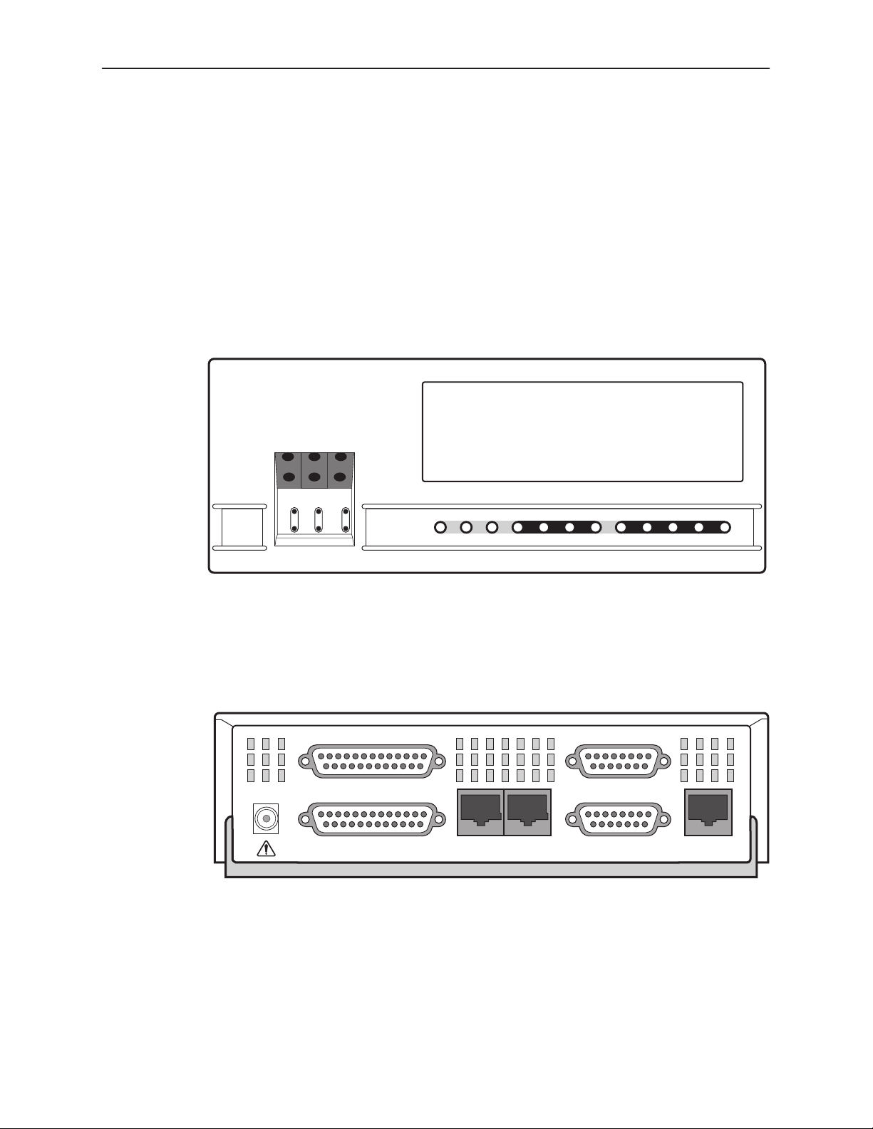
Physical Description
The DSU/CSU front panel (Figure 1-1) contains twelve light-emitting diodes
(LEDs) and six test jacks.
Introduction
The LEDs are described in the
The test jacks are described in the
Front Panel LEDs
Test Jacks
section in Chapter 4,
section in Chapter 3,
Maintenance
The DSU/CSU rear panel (Figure 1-2) contains the connectors required for the
operation of the DSU/CSU. The connectors and their functions are listed in
Table 1-1.
ACCULINK
F1 F2 F3
MON EQPT
NET
3162
In
OutInOutInOut
OK
FAIL TEST SIG OOF ALRM
EER SIG ALRM PDVOOF BPV
NETWORK RXD
DTR TXD CTS RTS
Operation
496-15001
.
.
Figure 1-1. 3162 DSU/CSU Front Panel
POWER
PORT 2
PORT 1
AUX
Figure 1-2. 3162 DSU/CSU Rear Panel
COM
EXT. CLOCK
DSX-1
NETWORK
496-15002
3162-A2-GB20-30
March 1999
1-3
Page 18

Introduction
Table 1-1. DSU/CSU Rear Panel Connectors
Name Function
POWER Supplies power to the DSU/CSU by providing an attachment for the
ac power module.
AUX PORT Supports SNMP LAN Adapter or daisy-chain connections.
COM PORT Provides access to a locally connected PC, ASCII terminal or
printer, SNMP management link, or asynchronous terminal
interface.
NETWORK Provides access to the T1 network.
DTE Provides access to the DTE Drop/Insert (DSX-1) interface.
CLOCK IN Used to attach an external clock to the DSU/CSU.
PORTs 1–2 Used to connect the customer’s synchronous data DTE to the
DSU/CSU.
1-4
March 1999
3162-A2-GB20-30
Page 19
Installation
Overview
This chapter contains information for installing your DSU/CSU. It includes
application examples, cabling, and power-up information.
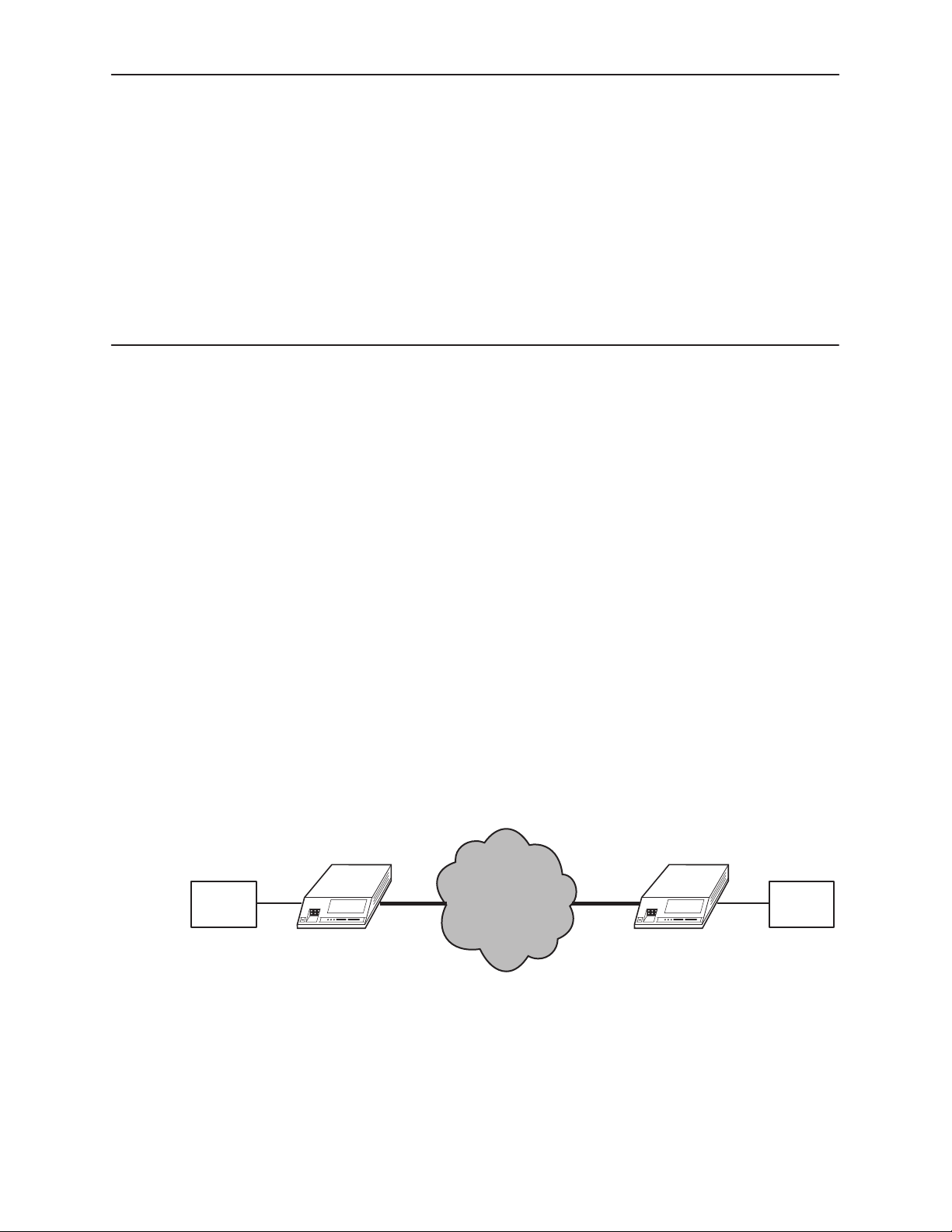
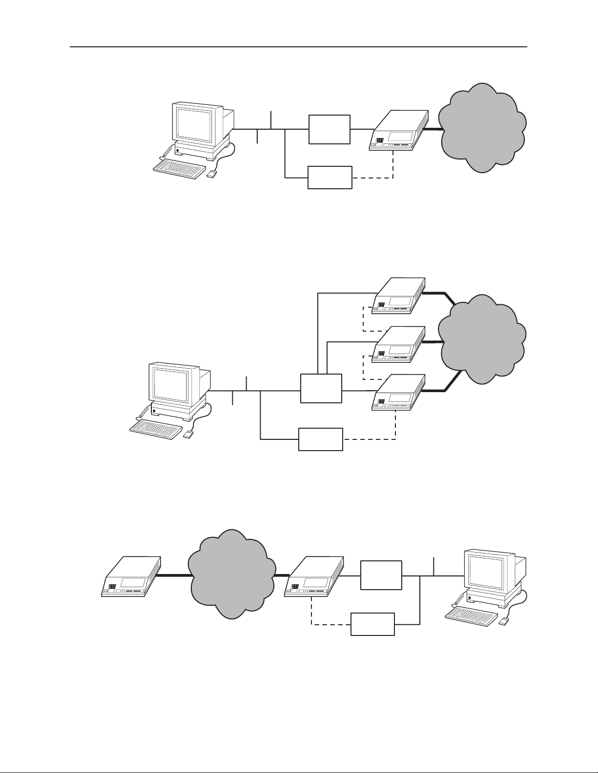
Application Examples
The DSU/CSU acts as an interface between the T1 digital network and the
customer’s equipment.
2
LAN
ROUTER
The DSU/CSU is connected to the customer’s equipment through one of the
synchronous data ports (PORTs 1–2) or the DTE Drop/Insert (DSX-1) interface. It
is connected to the T1 digital network through the network interface.
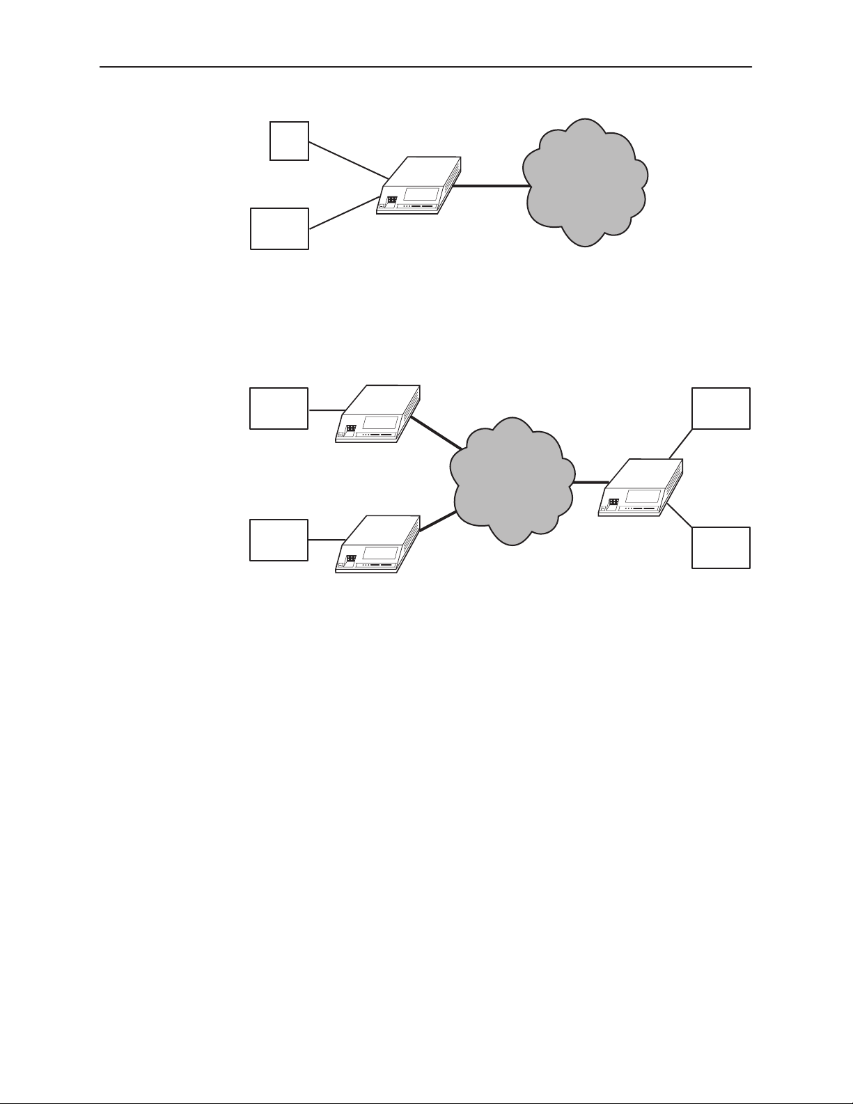
Some common applications for the DSU/CSU are:
Point-to-Point LAN interconnection (Figure 2-1).
Shared access to network-based services (Figure 2-2).
Fractional T1 network applications (Figure 2-3).
NETWORK
DSU/CSU
Figure 2-1. Point-to-Point Application Example
DSU/CSU
LAN
ROUTER
496-15218
3162-A2-GB20-30
March 1999
2-1
Page 20
Installation
PBX
NETWORK
SERVICES
LAN
ROUTER
DSU/CSU
Figure 2-2. Shared Access Application Example
LAN
ROUTER
DSU/CSU
FRACTIONAL
NETWORK
LAN
ROUTER
DSU/CSU
Figure 2-3. Fractional T1 Application Example
496-15219
LAN
ROUTER
DSU/CSU
LAN
ROUTER
496-15220
2-2
March 1999
3162-A2-GB20-30
Page 21
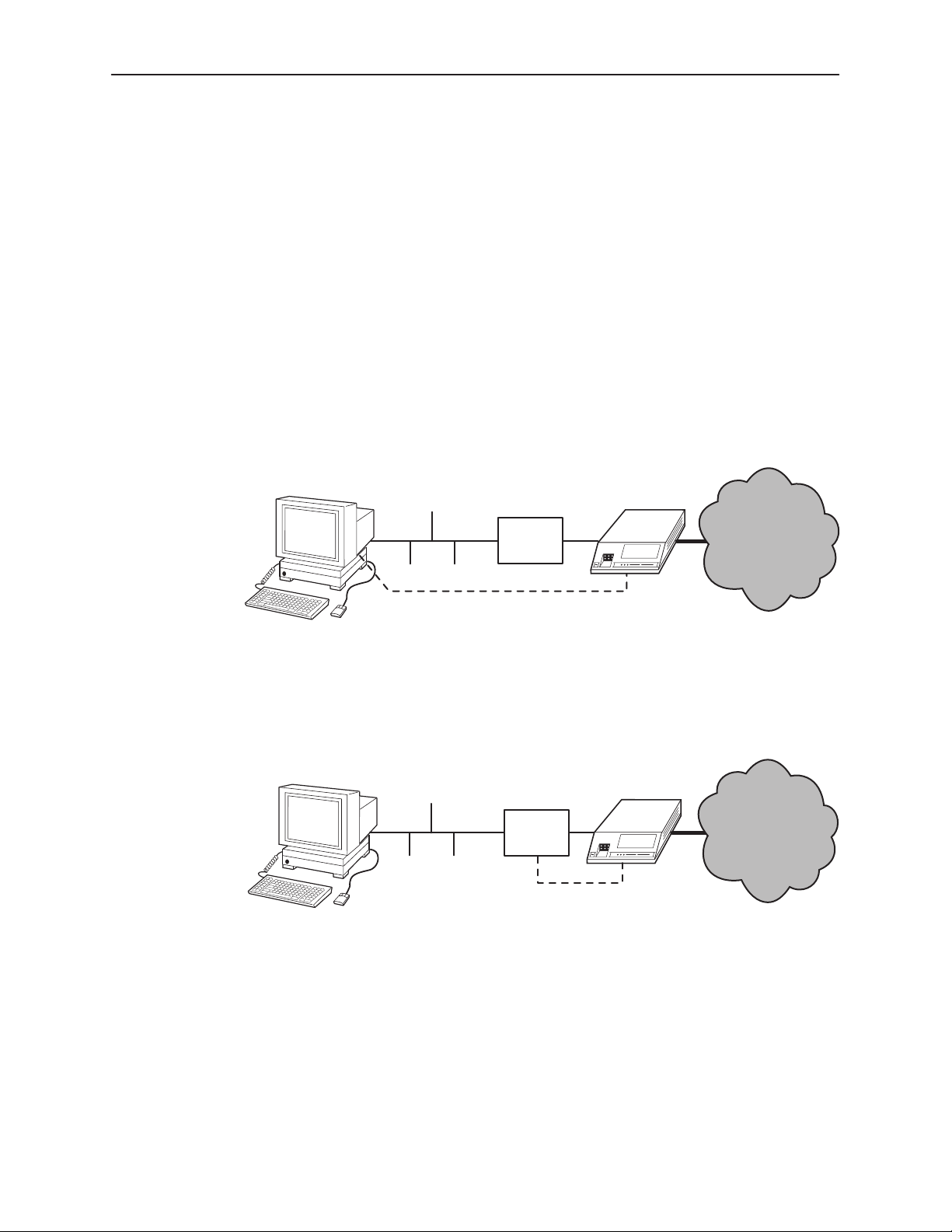
SNMP or Telnet Connection Examples
The DSU/CSU can be connected to an SNMP or Telnet system in a number of
ways. Some examples include:
Directly connecting the COM port to the SNMP or Telnet device (Figure 2-4).
Connecting the COM port to a network device (e.g., a router) (Figure 2-5).
Connecting the COM port or the AUX port to an external LAN Adapter for
Ethernet connectivity (Figure 2-6).
Daisy chaining the COM port of one device to the AUX port of the other
(Figure 2-7).
Remotely accessing the DSU/CSU through the Facility Data Link (FDL) or the
synchronous data port’s Embedded Data Link (EDL) (Figure 2-8).
Installation
ETHERNET
PPP/SLIP
Figure 2-4. Direct Connection
ETHERNET
LAN
ROUTER
LAN
ROUTER
DSU/CSU
NETWORK
496-15221
DSU/CSU
NETWORK
PPP/SLIP
496-15222
3162-A2-GB20-30
Figure 2-5. Connection through a Router
March 1999
2-3
Page 22
Installation
ETHERNET
LAN
ROUTER
LAN
ADAPTER
PPP
Figure 2-6. Connection through a LAN Adapter
PPP
ETHERNET
ROUTER
PPP
LAN
DSU/CSU
NETWORK
496-15223
DSU/CSU
DSU/CSU
NETWORK
DSU/CSU
LAN
ADAPTER
Figure 2-7. LAN Adapter and Daisy Chaining
DSU/CSUDSU/CSU
NETWORK
FDL/EDL
PPP
Figure 2-8. Remote Access through FDL/EDL
PPP
LAN
ROUTER
LAN
ADAPTER
496-15224
ETHERNET
496-15225
2-4
March 1999
3162-A2-GB20-30
Page 23

Important Instructions
Read and follow all warning notices and instructions marked on the DSU/CSU or
included in this guide.
Installation
For a complete listing of the safety instructions, see the
Instructions
Cabling Examples
The DSU/CSU is supplied with an ac power module.
Optional cables are described in Appendix D,
Figure 2-9 illustrates some cabling examples.
POWER
NEC
CLASS 2
INPUT
COM
PORT
PORT 2
PORT 1
CAUTION:
AUX PORT OR COM PORT MUST NOT BE CONNECTED TO PSTN OR T1 NETWORK
NETWORK
AUX
PORT
COM
section at the beginning of this guide.
NETWORK
EXT. CLOCK
DSX-1
3162
DSU/CSU
NETWORK
3162
DSU/CSU
Important Safety
Pin Assignments
COM
PORT
PORT 2
NEC
CLASS 2
INPUT
PORT 1
CAUTION:
AUX PORT OR COM PORT MUST NOT BE CONNECTED TO PSTN OR T1 NETWORK
POWER
.
NETWORK
AUX
COM
PORT
EXT. CLOCK
DSX-1
NETWORK
POWER
TERMINAL
MANAGER
Figure 2-9. Cabling Examples
POWER
SNMP
OR
OR
TERMINAL
496-15011
3162-A2-GB20-30
March 1999
2-5
Page 24
Installation
Power-Up Self-Test
After you connect the DSU/CSU to a power source, the unit performs the
power-up self-test to ensure that it is in good working order. The DSU/CSU
performs this test on itself upon power-up or after a device reset, unless it has
been disabled by the Self-Test configuration option (see Appendix C,
Configuration Options
The self-test includes a basic processor test, a limited memory test, a code
checksum test, and basic verification tests of the internal components.
Procedure
The power-up self-test consists of the following steps:
1. Once the DSU/CSU is plugged in, the Fail LED blinks ON and Off
).
continuously.
2. All the LEDs then start to flash simultaneously in the pattern twice ON, then
Off.
3. If the self-test is successful, the Fail LED turns Off and the OK LED lights.
If the self-test fails, the Fail LED lights. The DSU/CSU continues to try to
operate. If you are in doubt about the results of the self-test, use the System
and Test Status screen to display the results of this test (see
Results
in Chapter 4,
Maintenance
).
Self-Test
2-6
March 1999
3162-A2-GB20-30
Page 25

Operation
Overview
This chapter contains information for operating your DSU/CSU. It includes a
description of the front panel LEDs and sample procedures to help you become
familiar with the use of the asynchronous terminal for DSU/CSU control.
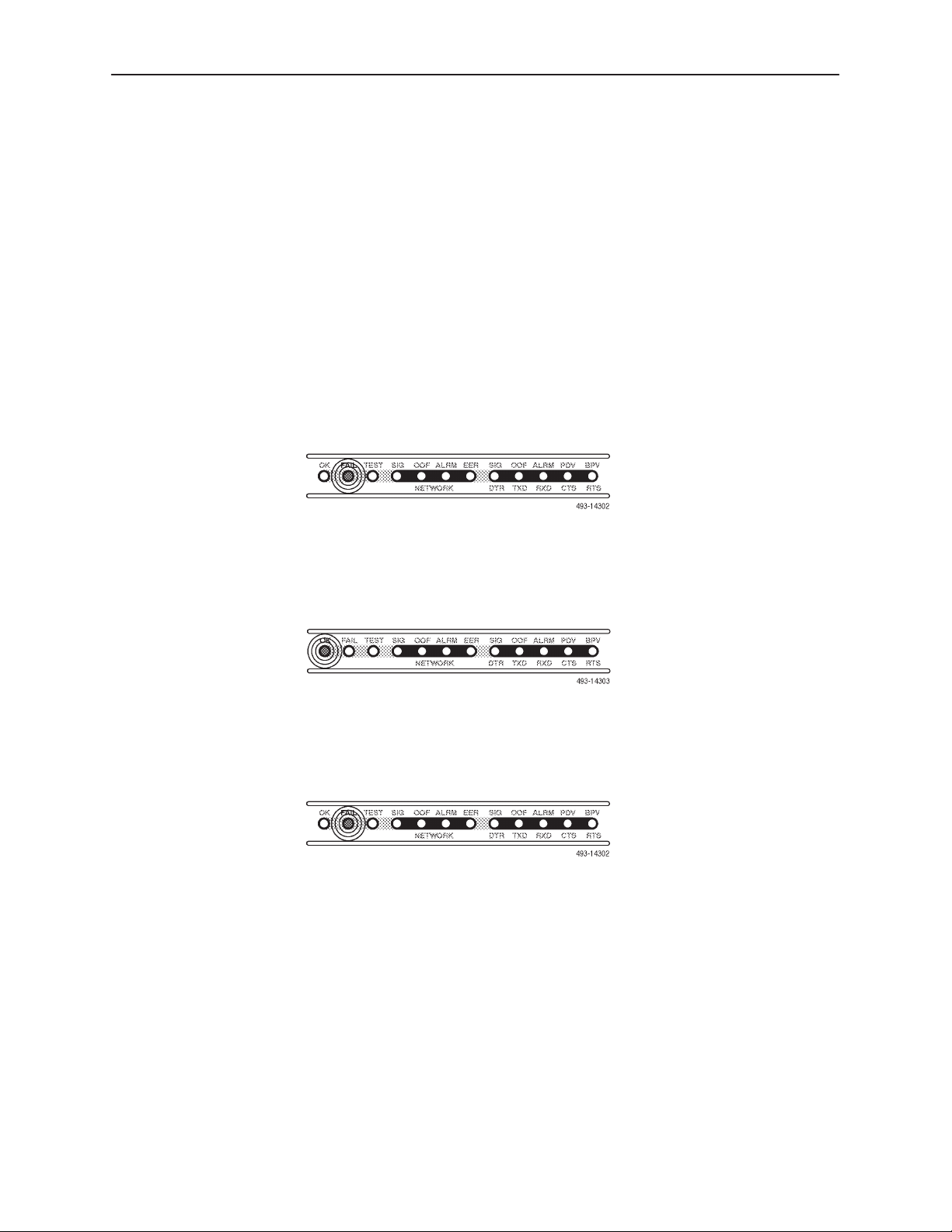
Front Panel LEDs
There are twelve LEDs on the DSU/CSU front panel. The five LEDs on the right
(Figure 3-1) are shared between the DTE Drop/Insert (DSX-1) interface and the
data ports. Use the Control branch of the asynchronous terminal menu tree to
choose which port’s status the LEDs display (see
page 3-7).
Menu Organization
3
on
3162-A2-GB20-30
Figure 3-1. DSU/CSU LEDs
A green LED indicates normal operation. A yellow LED indicates a warning (for
the DTE Drop/Insert interface) or activity (for the data ports). Conditions are
sampled every tenth of a second.
The twelve front panel LEDs are grouped into four sections to indicate the status
of the:
System (Table 3-1)
Network Interface (Table 3-2)
DTE Drop/Insert (DSX-1) Interface (Table 3-3)
Data Ports (Table 3-4)
March 1999
3-1
Page 26

Operation
Table 3-1. System LEDs
Name Color Meaning
OK Green Indicates the current operational state of the DSU/CSU.
ON:
OFF:
BLINKING:
FAIL Yellow Indicates a system failure or a self-test.
ON:
OFF:
BLINKING
TEST Yellow A system test is in progress.
ON:
OFF:
The DSU/CSU is operational and has power.
The DSU/CSU is performing a power-up self-test
or a system failure has occurred.
A software download is in progress.
A device error/fault is detected or a reset has just
occurred.
No system failures are detected.
: A self-test is in progress.
A loopback or pattern test has been initiated
either locally , by the network, or externally.
No tests are active.
Table 3-2. Network Interface LEDs
Name Color Meaning
SIG Green Monitors the signal being received from the network.
ON:
OFF:
OOF Yellow Monitors Out Of Frame (OOF) conditions on the received network
signal.
ON
: At least one OOF was detected on the signal during the
OFF:
ALRM Y ellow Indicates whether an alarm condition exists on the received network
signal.
ON:
OFF:
EER Yellow Indicates the Excessive Error Rate (EER) has been exceeded on the
network interface.
NOTE: This LED is only valid when ESF framing is being used.
ON:
OFF:
A recoverable signal is being received from the
network.
The signal cannot be recovered from the network
(a Loss of Signal condition exists).
sampling period.
No OOFs were detected on the signal during the
sampling period.
An alarm condition (LOS, LOF, EER, Yellow, AIS)
exists on the received network signal. Use the System
and Test Status screen to determine the alarm type.
No alarm condition exists on the network interface
signal.
The EER has been exceeded on the network
interface.
The EER has not been exceeded on the network
interface.
3-2
March 1999
3162-A2-GB20-30
Page 27

Operation
Table 3-3. DTE Drop/Insert (DSX-1) Interface LEDs
Name Color Meaning
SIG Green Monitors the signal being received from the DTE Drop/Insert
(DSX-1) interface.
ON:
OFF:
OOF Yellow Monitors Out Of Frame (OOF) conditions on the received DTE
Drop/Insert (DSX-1) signal.
ON:
OFF:
ALRM Yellow Indicates whether an alarm condition exists on the received DTE
Drop/Insert (DSX-1) signal.
ON:
OFF:
A recoverable signal is being received from the
DTE Drop/Insert (DSX-1) interface.
The signal cannot be recovered from the DTE
Drop/Insert (DSX-1) interface (a Loss of Signal
condition exists).
At least one OOF was detected on the signal
during the sampling period.
No OOFs were detected on the signal during the
sampling period.
An alarm condition (LOS, LOF, EER, Yellow, AIS)
exists on the received DTE Drop/Insert (DSX-1)
signal. Use the Device Health and Status
command to determine the alarm type.
No alarm condition exists on the DTE Drop/Insert
(DSX-1) interface signal.
PDV Yellow Monitors Pulse Density Violations (PDV) on the received DTE
Drop/Insert (DSX-1) signal.
ON
: At least one PDV was detected (and corrected)
OFF:
BPV Yellow Monitors Bipolar Violations (BPV) on the received DTE
Drop/Insert (DSX-1) signal.
ON:
OFF:
on the received DTE Drop/Insert (DSX-1) signal
during the sampling period.
No PDVs were detected on the received DTE
Drop/Insert (DSX-1) signal during the sampling
period.
At least one BPV was detected (and corrected)
on the received DTE Drop/Insert (DSX-1) signal
during the sampling period.
No BPVs were detected on the received DTE
Drop/Insert (DSX-1) signal during the sampling
period.
3162-A2-GB20-30
March 1999
3-3
Page 28

Operation
Table 3-4. Data Port LEDs
Name Color Meaning
DTR Green Monitors the state of interchange circuit CD (CCITT 108/1, /2) –
Data Terminal Ready received from the synchronous data DTE.
ON:
OFF:
TXD Yellow Monitors activity on interchange circuit BA (CCITT 103) –
Transmitted Data. This is the data sent from the synchronous
data DTE to the data port on the DSU/CSU.
ON:
OFF:
CYCLING:
RXD Yellow Monitors activity on interchange circuit BB (CCITT 104) –
Received Data. This is data sent to the synchronous data DTE
from the data port on the DSU/CSU.
ON:
OFF:
CYCLING:
DTR is being asserted by the synchronous data
DTE.
DTR is not being asserted.
Ones are being received from the synchronous
data DTE.
Zeros are being received from the synchronous
data DTE.
Both ones and zeros are being received from the
synchronous data DTE.
Ones are being sent to the synchronous data
DTE.
Zeros are being sent to the synchronous data
DTE.
Both ones and zeros are being sent to the
synchronous data DTE.
CTS Yellow Monitors the state of interchange circuit CB (CCITT 106) –
Clear-to-Send sent to the synchronous data DTE.
ON:
OFF:
RTS Yellow Monitors the state of interchange circuit CA (CCITT 105) –
Request-to-Send received from the synchronous data DTE.
ON:
OFF:
CTS is being asserted by the DSU/CSU.
CTS is not being asserted.
RTS is being asserted by the synchronous data
DTE.
RTS is not being asserted.
3-4
March 1999
3162-A2-GB20-30
Page 29
Initiating an Asynchronous Terminal Session
You can configure and manage the DSU/CSU from an asynchronous terminal
that is configured for 9.6 kbps, 8 characters, no parity, and 1 stop bit.
You can connect the asynchronous terminal directly to the COM port of the
DSU/CSU, or you can establish a remote connection using dial-in or Telnet
access.
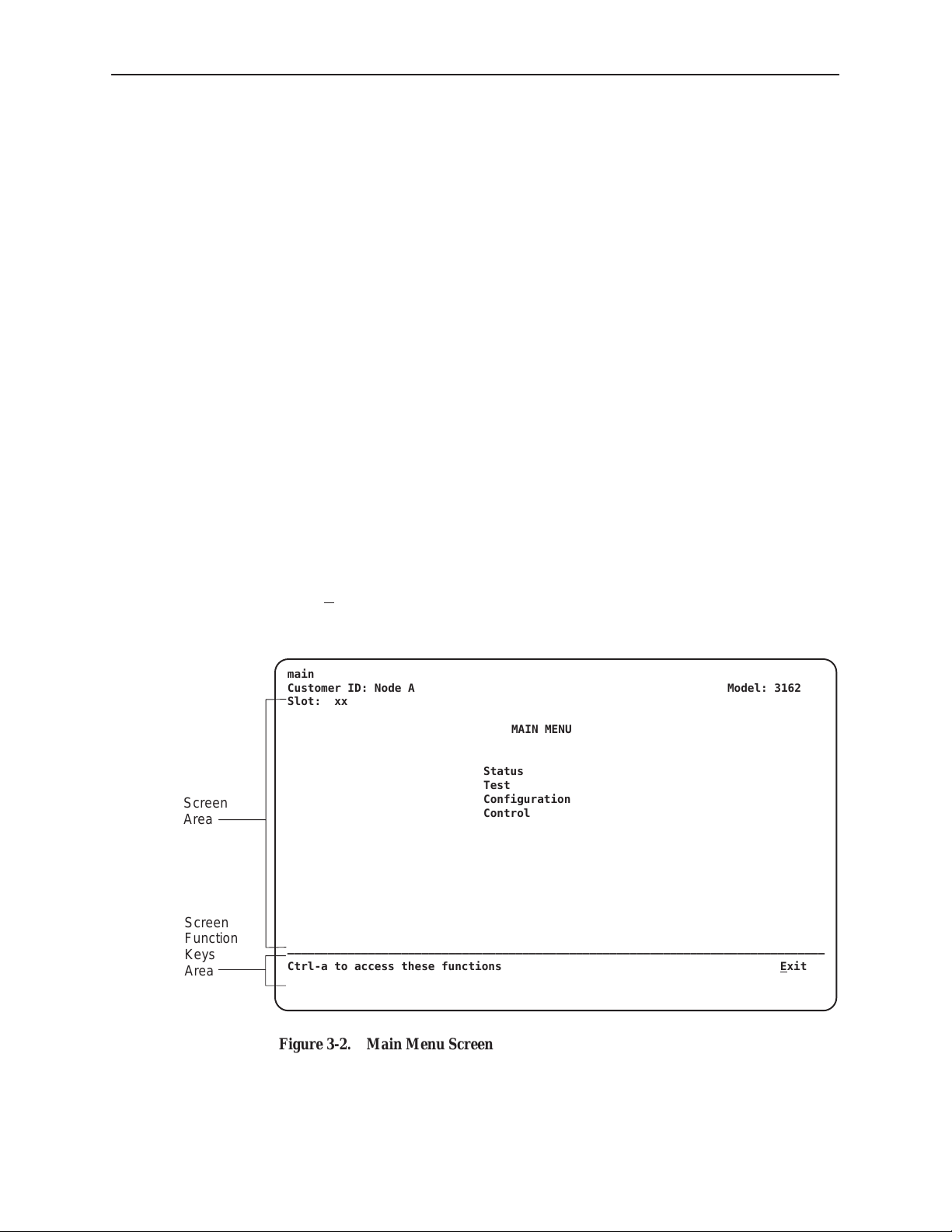
Once the appropriate access is established, the Main Menu screen (Figure 3-2)
appears (unless a password is required).
If a password is required, the Login screen displays the prompt for password
input. (Refer to
To move between the Screen area and the Screen Function Keys area
(Figure 3-2 ), press Ctrl-a (Control key and a).
From the Screen area, you may select the Status, Test, Configuration, or
Control branches.
Entering a Password to Gain Access
Operation
on page 3-32.)
Ending an Asynchronous Terminal Session
To end the asynchronous terminal session from any screen, press Ctrl-a to move
from the Screen area to the Screen Function Keys area (Figure 3-2), and then
select Exit.
main
Customer ID: Node A Model: 3162
Slot: xx
MAIN MENU
Status
Test
Screen
Area
Screen
Function
Keys
Area
––––––––––––––––––––––––––––––––––––––––––––––––––––––––––––––––––––––––––––––––
Ctrl-a to access these functions E
Configuration
Control
xit
3162-A2-GB20-30
Figure 3-2. Main Menu Screen
March 1999
3-5
Page 30

Operation
Recovering Asynchronous Terminal Operation
If the DSU/CSU is misconfigured, leaving it in a state that does not support
asynchronous terminal operation, use the following recovery procedure.
Procedure
1. Power cycle the DSU/CSU, waiting for the completion of the power-up
self-test.
2. Press the asynchronous terminal’s Return key five times in succession.
(Begin pressing the Return key within two seconds after the completion of
power-up self-test, and do not wait longer than one second between each
successive key press.)
3. The System Paused screen appears. Use it to reset the COM port
configuration options or to reload all factory default configuration options.
3-6
March 1999
3162-A2-GB20-30
Page 31

Menu Organization
Figure 3-3 shows the organization of the asynchronous terminal menu tree.
Operation
Main
System and
Test Status
DTE Channel
Display
Network
Channel
Display
Cross Connect
Status
Port
Assignment
Display
Network
Status
Display
LEDs
Performance
Statistics
Sync Data
Port
Clear
Statistics
Network DTE
Identity
Network &
DTE T ests
Sync Data
Port T ests
Sync Data
Ports
Test
Device
T ests
Copy
Ports
DTE to
Network
Assignments
Configuration Control
Call
Directories
Call
Customer ID
User
Interface
Abort
T ests
Assignments
Configuration
Edit/Display
Cross
Connect
Sync Data
Port
Setup
General
Options
Clear
Assignments
Administer
Password
Download
Alarms
& Traps
Select
Monitor Jack
Start
Management
and
Communication
Reset
Device
Select
LEDs
3162-A2-GB20-30
Figure 3-3. Menu Organization
March 1999
Communication
Port
Communication
Protocol
External
Device
General SNMP
Management
Sessions
Telnet
Auxiliary
Port
SNMP NMS
Security
SNMP
Traps
496-15013
3-7
Page 32

Operation
Using Asynchronous Terminal Screens
There are three types of asynchronous terminal screens.
Menu screens list selections available through the menu system.
Input screens allow you to edit or change information on a screen using
screen function keys (Table 3-5) or keyboard keys (Table 3-6).
Display screens show the results from a data collection operation or they
display device-specific information.
The asynchronous terminal supports character matching for entering values in
fields. For example, if the values for a field can be DTE, NET, or PORT and you
enter a D and press Return (Enter), then the field automatically populates with
the value DTE.
Once an operation is initiated, status messages appear in the last row of the
screen. These include Please Wait (when a command takes longer than five
seconds) and Command Complete.
Table 3-5. Screen Function Keys
Screen Function Key
M (MainMenu) Returns to the Main Menu screen.
E (Exit) Terminates the asynchronous terminal session.
R (Refresh) Updates the screen with the current information.
U (PgUp) Pages up to the previously displayed page of information.
D (PgDn) Pages down to the previously displayed page of
S (Save) Stores changes in nonvolatile memory .
Usage
information.
3-8
March 1999
3162-A2-GB20-30
Page 33

Operation
Table 3-6. Keyboard Keys
Keyboard Key Usage
Ctrl-a Moves the cursor between the Screen area and the
Screen Function Keys area.
Esc Returns to the previous screen.
Tab Moves the cursor to the next field.
Back (Shift) Tab or Ctrl-k Moves the cursor to the previous field.
Backspace Moves the cursor one position to the left or to the last
character of the previous field.
Spacebar Selects the next valid value for the field.
Delete Deletes the character that the cursor is on.
Up Arrow key or Ctrl-u Moves the cursor up one field within a column on the
same screen.
Down Arrow key or Ctrl-d Moves the cursor down one field within a column on the
same screen.
Right Arrow key or Ctrl-f Moves the cursor back one character to the right.
Left Arrow key or Ctrl-b Moves the cursor back one character to the left.
Ctrl-l Redraws the screen display.
Return (Enter) Accepts entry.
NOTE:
Some Telnet applications may require the use of Ctrl-u, Ctrl-d, Ctrl-f, and
Ctrl-b as an alternative to the use of the Up, Down, Right, and Left Arrow
keys.
3162-A2-GB20-30
March 1999
3-9
Page 34

Operation
NOTE:
The following procedures are examples only. This chapter uses examples to
help you become familiar with the use of the asynchronous terminal for
DSU/CSU control.
Setting Customer Identification
The customer identification is used to uniquely identify the DSU/CSU.
Procedure
To change the customer identification (Customer ID):
1. From the Main Menu screen, select Control.
2. From the Control screen, select Customer ID.
The Customer ID screen appears (Figure 3-4).
3. Use the Customer ID field to set the customer identification.
The customer identification may be up to 8 characters long.
Select Clear to remove all the characters in the associated field.
Customer
Identification
Field
4. Select S
ave to store the information in nonvolatile memory.
In addition to the customer identification, you may also enter a system name,
system location, and system contact. Although only 40 characters are displayed
for these fields, you may enter up to 255 characters. The fields scroll as the
additional characters are added.
main/control/customer id
Customer ID: Node A Model: 3162
Slot: xx
CUSTOMER ID
Customer ID:
System Name:
System Location:
System Contact:
––––––––––––––––––––––––––––––––––––––––––––––––––––––––––––––––––––––––––––––––
Ctrl-a to access these functions, ESC for previous menu M
S
ave
Clear
Clear
Clear
Clear
ainMenu Exit
3-10
Figure 3-4. Customer Identification Screen
March 1999
3162-A2-GB20-30
Page 35

Displaying LED Conditions
The same conditions monitored by the front panel LEDs can also be monitored
by the Display LEDs screen. This screen is most useful when the DSU/CSU is
being accessed remotely.
Procedure
To display LED conditions:
1. From the Main Menu screen, select Status.
2. From the Status screen, select Display LEDs.
The Display LEDs screen appears (Figure 3-5).
The screen shows a snapshot of the LEDs every 5 seconds. LEDs that are
illuminated are displayed by inverse video.
Select Refresh to update the screen.
Operation
main/status/leds
Customer ID: Node A Model: 3162
Slot: xx
DISPLAY LEDs
GENERAL NETWORK DTE PORT 1 PORT 2
OK Sig Sig DTR DTR
Fail OOF OOF TXD TXD
Test Alm Alm RXD RXD
––––––––––––––––––––––––––––––––––––––––––––––––––––––––––––––––––––––––––––––––
Ctrl-a to access these functions, ESC for previous menu M
R
efresh
EER PDV CTS CTS
BPV RTS RTS
ainMenu Exit
Figure 3-5. Example of Display LEDs Screen
3162-A2-GB20-30
March 1999
3-11
Page 36

Operation
Changing Configuration Options
The DSU/CSU is an intelligent device that displays only valid options for the
current configuration. Therefore, you are only presented with menu choices that
are consistent with the current configuration and operational state of the
DSU/CSU; invalid combinations of configuration options do not appear. For
example, if the DTE Drop/Insert (DSX-1) interface selection is disabled, many of
the menu choices do not appear.
The DSU/CSU offers configuration options located in the following memory areas:
Current. This is the configuration option set currently active for the DSU/CSU
is stored here. Before a configuration option set becomes active for the
DSU/CSU, you must save the set to the Current area. When the DSU/CSU is
shipped from the factory, the Current configuration option set is identical to
the Default Factory set. This area can be written to and controls the current
operation of the device.
Customer 1. This is the first of two sets of customer-defined configuration
options. This area can be written to.
Customer 2. This is the second of two sets of customer-defined configuration
options. This area can be written to.
Default Factory 1. This is a set of configuration options preset at the factory.
This set is determined by what is considered to be the most common
configuration used in the DSU/CSU market. Default Factory 1 options are
read-only.
Default Factory 2. This is a set of configuration options preset at the factory.
This set is determined by what is considered to be the second most common
configuration used in the DSU/CSU market. Default Factory 2 options are
read-only.
The configuration options are divided into functional groups. Appendix C contains
a list of the configuration options and defaults.
The DSU/CSU arrives with two preset factory default configuration settings.
These settings are based on the following:
Default Factory 1 – ESF framing format with B8ZS line coding format for
both the network and the DTE Drop/Insert (DSX-1) interfaces. Data ports are
unassigned.
Default Factory 2 – D4 framing format with AMI line coding format for both
the network and the DTE Drop/Insert (DSX-1) interfaces. Data ports are
unassigned.
If neither of the factory default settings support your network’s configuration, you
can customize the configuration options to better suit your application.
3-12
Use the Configuration branch of the menu tree to display or change DSU/CSU
configuration options (see Appendix C,
March 1999
Configuration Options
).
3162-A2-GB20-30
Page 37

Displaying or Editing Configuration Options
Procedure
To display or edit configuration options:
1. From the Main Menu screen, select Configuration.
The Load Configuration From screen appears (Figure 3-6).
2. From the Load Configuration From screen, select a configuration option set
to load (Current, Customer 1, Customer 2, Default Factory 1, or Default
Factory 2). You cannot edit the Default Factory configuration options, but you
can display them.
After selecting the set of configuration options to load, the Configuration
Edit/Display screen appears (Figure 3-7).
3. Select a functional group to display or edit.
NOTE:
Screen displays may vary depending on the configuration of the
DSU/CSU.
Operation
main/config
Customer ID: Node A Model: 3162
Slot: xx
LOAD CONFIGURATION FROM:
Current Configuration
Customer Configuration 1
Customer Configuration 2
Default Factory Configuration 1
Default Factory Configuration 2
––––––––––––––––––––––––––––––––––––––––––––––––––––––––––––––––––––––––––––––––
Ctrl-a to access these functions, ESC for previous menu M
ainMenu Exit
Figure 3-6. Configuration Load Screen
3162-A2-GB20-30
March 1999
3-13
Page 38

Operation
main/config/edit
Customer ID: Node A Model: 3162
Slot: xx
CONFIGURATION EDIT/DISPLAY
Network
DTE
Sync Data Ports
Copy Ports
Cross Connect
General Options
User Interface
Alarms & Traps
Management and Communication
––––––––––––––––––––––––––––––––––––––––––––––––––––––––––––––––––––––––––––––––
Ctrl-a to access these functions, ESC for previous menu M
ave
S
ainMenu Exit
Figure 3-7. Configuration Edit/Display Screen
3-14
March 1999
3162-A2-GB20-30
Page 39

Saving Edit Changes
Operation
Procedure
To save edit changes:
1. From the last edit screen, select Save.
The Save Configuration To screen appears (Figure 3-8).
2. From the Save Configuration To screen, select a configuration option set
(Current, Customer 1, or Customer 2).
Save edit changes to the Current area when you want those changes to take
effect immediately. Save edit changes to the Customer area when you want to
overwrite the existing Customer configuration options and store these changes
for future use.
To protect you from accidentally exiting an edit session before saving your
changes, the system displays the Save Changes? prompt if you select either
M
ainMenu or Exit from an edit screen. If you respond No, the system exits
without saving the changes. If you respond Yes, you are prompted to specify
where the changes should be saved.
main/config/save
Customer ID: Node A Model: 3162
Slot: xx
SAVE CONFIGURATION TO:
Current Configuration
Customer Configuration 1
Customer Configuration 2
––––––––––––––––––––––––––––––––––––––––––––––––––––––––––––––––––––––––––––––––
Ctrl-a to access these functions, ESC for previous menu M
ainMenu Exit
Figure 3-8. Configuration Save Screen
3162-A2-GB20-30
March 1999
3-15
Page 40

Operation
Configuring the DSU/CSU for SNMP or Telnet
Access
To configure the DSU/CSU for SNMP or Telnet access,
Enable the SNMP agent or Telnet server within the DSU/CSU (see
Appendix C,
Select and configure the port that provides the link to the SNMP or Telnet
system.
Set the Internet Protocol (IP) address and subnet mask needed to access the
DSU/CSU (see Appendix F,
Select the link layer protocol (PPP or SLIP) for the port that provides the link
to the SNMP or Telnet system.
For SNMP links, specify the two community names (and their access levels)
that are allowed to access the device’s Management Information Base (MIB)
(see Appendix C,
For SNMP links, configure the device to send traps to the SNMP manager, if
desired (see Appendix C,
Chapter 4,
Configuration Options
IP Network Addressing Scenario
Configuration Options
Configuration Options,
Maintenance
).
).
).
and
SNMP Traps
).
in
Specify the Telnet password or SNMP validation options, if desired (see
Appendix C,
Configuration Examples
NOTE:
The following procedures are examples only. This chapter uses examples to
help you become familiar with the use of the asynchronous terminal for
DSU/CSU control.
Configuration Options
).
3-16
March 1999
3162-A2-GB20-30
Page 41

Selecting the Port
Operation
The SNMP manager, Telnet device, or network device (e.g., a router) can be
directly connected to the COM port. An external LAN Adapter can be connected
to either the COM port or the auxiliary (AUX) port to provide Ethernet or Token
Ring connectivity. Also, the DSU/CSU can be daisy chained together by
connecting the COM port of one device to the AUX port of the other, providing
SNMP or Telnet connectivity.
The COM port can support either synchronous or asynchronous PPP, or
asynchronous SLIP at data rates of up to 38,400 bps. The AUX port can support
data rates up to 38,400 bps.
The following procedure is an example only. It assumes that the COM port is
being used as the link to the SNMP or Telnet system.
Procedure
To select the COM port as the SNMP or Telnet link:
1. From the Main Menu screen, select Configuration.
2. From the Load Configuration From screen, select Current.
3. From the Configuration Edit/Display screen, select User Interface.
4. From the User Interface screen, select Communication Port.
5. In the Port Use field, enter Mgmt (Figure 3-9).
6. When you are through making configuration option changes, select Save to
store these changes in nonvolatile memory. If you want to return to the User
Interface screen, press your Esc key and then save your changes from that
screen.
main/config/user/com
Customer ID: Node A Model: 3162
Slot: xx
COMMUNICATION PORT OPTIONS
Port Use: Mgmt
Port Type: Synchronous
Clock: Internal
Data Rate (Kbps): 9.6
Port Use
Field
––––––––––––––––––––––––––––––––––––––––––––––––––––––––––––––––––––––––––––––––
Ctrl-a to access these functions, ESC for previous menu M
ave
S
ainMenu Exit
Figure 3-9. Configuration Save Screen
3162-A2-GB20-30
March 1999
3-17
Page 42

Operation
Setting the IP Address
Procedure
The IP address is the address used by the SNMP or Telnet system to access the
DSU/CSU (see Appendix F,
using PPP, the IP address can be negotiated if the network device (e.g., router or
SNMP manager) supports such negotiation. The IP address is composed of four
fields with three digits per field (
The IP address is set for the COM port or the AUX port (with LAN Adapter or
daisy chain), depending on which one has been chosen as the SNMP or Telnet
communications link. The example below assumes that an IP address of
010.155.111.222 is being set for the COM port. You can use the same principles
to assign any value (between 000 and 255 for each digit field) to other ports.
To assign an IP address to the COM port:
1. From the Main Menu screen, select Configuration.
2. From the Load Configuration From screen, select Current.
3. From the Configuration Edit/Display screen, select Management and
Communication.
IP Network Addressing Scenario
xxx.xxx.xxx.xxx
).
). For DSU/CSUs
4. From the Management and Communication screen, select Communication
Protocol.
5. In the Communication Port’s IP Address field, enter the IP address for the
COM port. Enter the subnet mask under this.
6. When you are through making configuration option changes, select S
store these changes in nonvolatile memory. If you want to return to the User
Interface screen, press your Esc key and then save your changes from that
screen.
ave to
3-18
March 1999
3162-A2-GB20-30
Page 43

Selecting the Link Layer Protocol
Two link layer protocols, Point-to-Point Protocol (PPP) and Serial Line Internet
Protocol (SLIP), are supported for connection to an external SNMP manager,
Telnet device, or network device (e.g., a router). PPP can be used for
synchronous or asynchronous operation. SLIP can be used for asynchronous
operation only.
The DSU/CSU implementation of PPP supports the following:
H Full negotiation of PPP’s Link Control Protocol (LCP).
H Active negotiation of LCP when the connection is established.
H Maximum Request Unit (MRU) sizes up to 1500 bytes, but the DSU/CSU will
attempt to negotiate down to 500 bytes.
H The DSU/CSU provides a unique LCP magic number derived from the unit
serial number and the elapsed time.
H Full negotiation of escape characters.
The DSU/CSU implementation of PPP does not support Link Quality Reports
(LQR), compression, encryption, Password Authentication Protocol (PAP) or
Challenge Handshake Authentication Protocol (CHAP).
Operation
The DSU/CSU implementation of SLIP supports a fixed MRU size of 1006 bytes.
Before selecting the protocol, you must first select the port to be used as the
communications link. Refer to
assumes that the COM port is being used as the communications link.
Selecting the Port
on page 3-17. This example
" Procedure
To select the link layer protocol:
1. Select the Communication Protocol Options screen using the procedure
described in the previous section,
2. In the Communication Port’s Com Link Protocol field, enter PPP or SLIP.
3. When you are through making configuration option changes, select Save to
store these changes in nonvolatile memory. If you want to return to the User
Interface screen, press your Esc key and then save your changes from that
screen.
Setting the IP Address
.
3162-A2-GB20-30
March 1999
3-19
Page 44

Operation
Configuring DS0 Channels
The DSU/CSU provides Cross Connect configuration options that allow you to do
the following:
Display the DS0 assignments for the network, DTE Drop/Insert (DSX-1), and
data port interfaces.
Allocate DS0 channels on the DTE Drop/Insert (DSX-1) interface to the
network interface.
Allocate DS0 channels on the network or DTE Drop/Insert (DSX-1) interface
to particular data ports.
Map data from one port to another.
Clear (deallocate) all DS0 channels from the network, DTE Drop/Insert
(DSX-1), or data port interface.
To allocate DS0 channels, begin by defining the logical channel configuration for
the network interface, and then the DTE Drop/Insert (DSX-1) interface, and then
any ports, if desired. See Figure 3-10 for an example of a conceptual diagram of
a channel configuration.
Blank configuration worksheets are provided at the back of Appendix C,
Configuration Options
procedures in this section. Figure 3-11 and Figure 3-12 are provided as an
example only. See Appendix C for other useful worksheets.
. These worksheets will help you prepare to perform the
NOTE:
The procedures in this section are examples only. Screen displays may vary
depending on the configuration of the DSU/CSU. For example, the DTE
Drop/Insert (DSX-1) interface is not displayed if this interface is disabled.
3-20
March 1999
3162-A2-GB20-30
Page 45

NETWORK
INTERFACE
N1
N2
N3
N4
N5
N6
N7
N8
N9
N10
N11
N12
N13
N14
N15
N16
N17
N18
N19
N20
N21
N22
N23
N24
Operation
DTE DROP/INSERT
(DSX-1) INTERFACE
D1
D2
D3
D4
D5
D6
D7
D8
D9
D10
D11
D12
D13
D14
D15
D16
D17
D18
D19
D20
D21
D22
D23
D24
PORTS
PRT 1
PRT 2
496-15016
3162-A2-GB20-30
Figure 3-10. Example of Channel Allocation
March 1999
3-21
Page 46

Operation
Network Interface
Network Channel Allocation
N1
N2
N3
N4
N5
N6
N7
N8
N9
N10
N1 1
N12
N13
N14
N15
D1
D2
D3
D4
D5
D9
D10
D1 1
D12
D15
Prt1
Prt1
N16
N17
N18
N19
N20
N21
N22
N23
N24
Allocations
D1 – D24 indicates allocation to DTE Drop/Insert (DSX-1) channels.
Prt1 – Prt2 indicates allocation to synchronous data ports.
Prt1
Prt2
Prt2
Prt2
Prt2
Prt2
Prt2
Figure 3-11. Example of Network Interface Worksheet
3-22
March 1999
3162-A2-GB20-30
Page 47

DTE Drop/Insert (DSX-1) Interface
DTE (DSX-1) Channel Allocation
Operation
D1
D2
D3
D4
D5
D6
D7
D8
D9
D10
D1 1
D12
D13
D14
D15
N1
N2
N3
N4
N5
N9
N10
N1 1
N12
N13
D16
D17
D18
D19
D20
D21
D22
D23
D24
Allocations
N1 – N24 indicates allocation to network channels.
Figure 3-12. Example of DTE Drop/Insert Interface W orksheet
3162-A2-GB20-30
March 1999
3-23
Page 48

Operation
Displaying DS0 Channel Assignments
Use the DTE to Network Assignments screen (in the Cross Connect branch) to
view how the DS0 channels are currently allocated. DS0 designations used on
this screen are shown in Table 3-7.
Table 3-7. DTE to Network DS0 Designations
Designation Meaning
Available The DS0 channel is not allocated.
Assigned The DS0 channel is allocated to one of the data ports.
N
nn
DTE
nn
The DS0 channel is allocated to the network interface DS0
nn
channel
24.
The DS0 channel is allocated to the DTE Drop/Insert
(DSX-1) interface DS0 channel nn, where nn can be any
number from 01 through 24.
, where nn can be any number from 01 through
3-24
March 1999
3162-A2-GB20-30
Page 49

Procedure
To display the DS0 channel allocation:
1. From the Main Menu screen, select Configuration.
2. From the Load Configuration From screen, select Current.
3. From the Configuration Edit/Display screen, select Cross Connect.
4. From the Cross Connect screen, select DTE To Network Assignments.
The DTE to Network Assignments screen appears (Figure 3-13).
5. To view specific port assignments on the Network Channel Display screen,
select N
main/config/cross_connect/dte
Customer ID: Node A Model: 3162
Slot: xx
etChan at the bottom of the DTE to Network Assignments screen.
DTE (DSX-1) TO NETWORK ASSIGNMENTS
Operation
NetChan
Selection
N01 N02 N03 N04 N05 N06 N07 N08
DTE01
N09 N10 N11 N12 N13 N14 N15 N16
DTE09
N17 N18 N19 N20 N21 N22 N23 N24
Available
––––––––––––––––––––––––––––––––––––––––––––––––––––––––––––––––––––––––––––––––
Ctrl-a to access these functions, ESC for previous menu M
S
DTE02 DTE03 DTE04 DTE05 Available Available Available
DTE10 DTE11 DTE12 DTE15 Assigned Assigned Assigned
Assigned Assigned Assigned Assigned Assigned Assigned Available
ainMenu Exit
ave NetChan DTEChan PtAssign
Figure 3-13. Example of DTE Drop/Insert Interface W orksheet
3162-A2-GB20-30
March 1999
3-25
Page 50

Operation
Allocating DS0 Channels from the DTE Drop/Insert Interface to the
Network Interface
Procedure
To allocate DS0 channels from the DTE Drop/Insert (DSX-1) interface to the
network interface:
1. From the Main Menu screen, select Configuration.
The Load Configuration From screen appears.
2. From the Load Configuration From screen, select Current.
The Configuration Edit/Display screen appears.
3. From the Configuration Edit/Display screen, select Cross Connect.
The Cross Connect screen appears.
4. From the Cross Connect screen, select DTE To Network Assignments.
The DTE to Network Assignments screen appears (Figure 3-14).
5. Assign the DS0 channels from the DTE Drop/Insert (DSX-1) interface to the
network interface. In the example shown in Figure 3-13, the DTE Drop/Insert
(DSX-1) DS0 channel 01 is assigned to the network DS0 channel 01.
DTE to
Network
Assignment
6. Select S
main/config/cross_connect/dte
Customer ID: Node A Model: 3162
Slot: xx
N01 N02 N03 N04 N05 N06 N07 N08
DTE01
N09 N10 N11 N12 N13 N14 N15 N16
Available
N17 N18 N19 N20 N21 N22 N23 N24
Available
––––––––––––––––––––––––––––––––––––––––––––––––––––––––––––––––––––––––––––––––
Ctrl-a to access these functions, ESC for previous menu M
ave NetChan DTEChan PtAssign
S
ave to store these settings in nonvolatile memory.
DTE (DSX-1) TO NETWORK ASSIGNMENTS
Available Available Available Available Available Available Available
Available Available Available Available Assigned Assigned Assigned
Assigned Assigned Assigned Assigned Assigned Assigned Available
ainMenu Exit
Figure 3-14. Making DTE to Network Assignments
3-26
March 1999
3162-A2-GB20-30
Page 51

Configuring DS0 Channels for Robbed Bit Signaling
By using the DTE configuration options, you can specify which DS0 channels
carry Robbed Bit Signaling (RBS) information for voice channels.
Procedure
To specify DTE Drop/Insert (DSX-1) channels used to carry voice information:
1. From the Main Menu screen, select Configuration.
The Load Configuration From screen appears.
2. From the Load Configuration From screen, select Current.
The Configuration Edit/Display screen appears.
3. From the Configuration Edit/Display screen, select DTE.
The DTE Interface Options screen appears (Figure 3-15).
4. Enter RBS for each DS0 channel that you want to configure for voice
applications.
The designation None indicates the absence of RBS information. These
channels (known as Clear Channels) are used for data applications.
Operation
Configured
for RBS
5. Select S
main/config/dte
Customer ID: Node A Model: 3162
Slot: xx DTE INTERFACE OPTIONS
Signaling: D01 D02 D03 D04 D05 D06 D07 D08
––––––––––––––––––––––––––––––––––––––––––––––––––––––––––––––––––––––––––––––––
Ctrl-a to access these functions, ESC for previous menu M
ave
S
ave to store these settings in nonvolatile memory.
Interface Status: Enable
Line Framing Format: ESF
Line Coding Format: B8ZS
Line Equalization: 0-133
DTE LB on External Contact: Disable
DTE
Send all Ones on DTE Failure: Enable
None
None None None None None None None
D09 D10 D11 D12 D13 D14 D15 D16
RBS
None None None None None None None
D17 D18 D19 D20 D21 D22 D23 D24
None
None None None None None None None
ainMenu Exit
Figure 3-15. DTE to Interface Options Screen
3162-A2-GB20-30
March 1999
3-27
Page 52

Operation
Allocating Data Ports Using the Block or ACAMI Assignment Method
By using the block or ACAMI (Alternate Channel Alternate Block Inversion)
assignment method, you can assign a data port to a block of contiguous DS0
channels on either the network interface or the DTE Drop/Insert (DSX-1)
interface.
The block assignment method allows a block of contiguous channels to be
assigned by specifying a data port rate and an initial DS0 channel (the first DS0
channel in a block of DS0 channels). The number of channels assigned is
determined by the port rate. These channels are automatically assigned to the
destination T1 interface (Network or DTE Drop/Insert) when the initial DS0
channel is selected.
The ACAMI assignment method also allows a block of contiguous channels to be
assigned, however, with ACAMI, the number of channels assigned is twice the
number needed for the port rate. This is because with ACAMI, every alternate
DS0 channel (starting with the
port, but instead always transmits and receives all ones.
n
+1 DS0 channel), does not carry data from the
Procedure
To assign data ports by the block or ACAMI method:
1. From the Main Menu screen, select Configuration.
2. From the Load Configuration From screen, select Current.
3. From the Configuration Edit/Display screen, select Cross Connect.
4. From the Cross Connect screen, select Sync Data Port Assignments.
5. Use the Assign To field to specify the destination T1 interface (Network or
DTE).
6. Use the Assign By field to specify the assignment method (Block or ACAMI).
7. After filling in the Port Rate field, specify a port assignment for the initial DS0
channel in a block of contiguous, available DS0 channels.
8. Select S
Esc key and then save your changes from that screen.
ave or, if you want to return to the Cross Connect screen, press your
3-28
March 1999
3162-A2-GB20-30
Page 53

Allocating Data Ports Using the Individual Channel Assignment
Method
By using the individual channel assignment method, you can assign a data port to
individual DS0 channels on either the network interface or the DTE Drop/Insert
(DSX-1) interface.
This method individually selects the DS0 channels to allocate to the data port.
The data port rate is automatically determined based on the number of channels
selected.
Procedure
To assign data ports by the individual channel method:
1. From the Main Menu screen, select Configuration.
2. From the Load Configuration From screen, select Current.
3. From the Configuration Edit/Display screen, select Cross Connect.
4. From the Cross Connect screen, select Sync Data Port Assignments.
5. Use the Assign To field to specify the destination T1 interface (Network or
DTE).
Operation
6. Use the Assign By field to specify the assignment method (Channel).
7. Specify the port assignments for the individual DS0 channels. The DS0
channels do not need to be contiguous.
The port rate increases as the port is assigned to additional DS0 channel. For
two DS0 channels (at 64 kbps each), a port rate of 128 kbps is required.
8. Select S
Esc key and then save your changes from that screen.
ave or, if you want to return to the Cross Connect screen, press your
Clearing DS0 Channel Allocation
You can clear (deallocate) all the DS0 channels currently allocated to either the
network interface, the DTE Drop/Insert (DSX-1) interface, or the synchronous
data ports.
Procedure
To clear DS0 channel allocation:
1. From the Main Menu screen, select Configuration.
2. From the Load Configuration From screen, select Current.
3. From the Configuration Edit/Display screen, select Cross Connect.
3162-A2-GB20-30
4. From the Cross Connect screen, select Clear Assignments.
5. To clear all DS0 channel allocations, select Clear All. Otherwise, select the
appropriate DS0 channel group to clear (DTE, Network, or Sync Data Ports).
A message will appear, Are You Sure?.
6. Enter Yes to clear the specified DS0 channels.
March 1999
3-29
Page 54

Operation
Establishing Access Security on a Port
Although the password feature is available, it is not required. If used, it ensures
access security before control is passed to a device connected to a port. The
following procedure is an example only. It shows how to enable the password for
the communication port. Passwords can also be enabled for the internal modem
and for Telnet sessions.
Procedure
To establish access security on the communication port:
1. From the Main Menu screen, select Configuration.
2. From the Load Configuration From screen, select Current.
3. From the Configuration Edit/Display screen, select User Interface.
4. From the User Interface Options screen, select Communication Port.
5. In the Password Required field, enter Enable.
6. Select S
7. From the Save Configuration To screen, select Current.
The password itself is set separately. Refer to the following section,
Password
ave to store this setting in nonvolatile memory.
.
Setting a
3-30
March 1999
3162-A2-GB20-30
Page 55

Setting a Password
In addition to establishing access security on a port (refer to the previous section,
Establishing Access Security on a Port
specify otherwise, the password is null.
Procedure
To set a password:
1. From the Main Menu screen, select Control.
2. From the Control screen, select Administer Password.
3. Enter a new password in the Password field.
4. Use the Re-Enter Password field to verify the new password.
Operation
), the password itself is set. Unless you
The Password Entry screen (Figure 3-16) is used to add a new password or
modify an existing password.
The password may be 1 to 8 characters long and may contain the characters
0 through 9, a through z, and/or A through Z.
Save
Password
5. Select S
ave.
Once a password is saved, the Login Records Saved message appears in
the last row of the screen.
main/control/admin_password
Customer ID: Node A Model: 3162
Slot: xx
PASSWORD ENTRY
Password:
Re-Enter Password:
––––––––––––––––––––––––––––––––––––––––––––––––––––––––––––––––––––––––––––––––
Ctrl-a to access these functions, ESC for previous menu M
S
ave
ainMenu Exit
Enter New
Password
Re-Enter
Password
3162-A2-GB20-30
Figure 3-16. Setting a Password
March 1999
3-31
Page 56

Operation
Entering a Password to Gain Access
When access security is required, the Login screen (Figure 3-17) appears before
you can access the Main Menu screen. The password must be entered.
If the password is valid
If the password is invalid
screen reappears and waits for password entry.
If an invalid password is entered three consecutive times
Interface Idle appears, Telnet sessions are closed, dial-in connections
are disconnected, and an SNMP trap is generated.
login
Customer ID: Node A Model: 3162
Slot: xx
LOGIN
Enter Password
, the DSU/CSU’s top-level menu appears.
, an invalid password message appears and the
, the message User
Enter
Password
––––––––––––––––––––––––––––––––––––––––––––––––––––––––––––––––––––––––––––––––
Ctrl-a to access these functions E
xit
Figure 3-17. Entering a Password
3-32
March 1999
3162-A2-GB20-30
Page 57

Selecting the Timing Source
The DSU/CSU provides the ability to select a master clock (timing) source that is
used to synchronize all of the T1 and data port interfaces on the DSU/CSU. The
clock for each interface is at the appropriate rate for that interface (e.g.,
1.544 Mbps for the T1 interfaces, the configured port rate for the data ports), and
it is independent of the master clock rate. This means that the master clock rate
and the DSU/CSU interface rates may be different.
The clock source configuration options enable you to select either the network
interface, a synchronous data port, the internal clock, the DTE Drop/Insert
(DSX-1) interface, or an external clock. If external clocking is selected, you must
use the clock rate configuration option to specify the clock rate. Figure 3-18
shows some common clocking configurations. For more information on
configuration options, refer to Appendix C.
Operation
NETWORK
CLOCK: NETWORK CLOCK: NETWORK
CLOCK: EXTERNAL CLOCK: NETWORK
PBX
CLOCK: DTE DROP/INSERT (DSX-1) CONNECTOR
TERMINAL
EQUIPMENT
CLOCK: PORT 1
CLOCK: NETWORKCLOCK: INTERNAL
CLOCK: NETWORK
CLOCK: NETWORK
496-15012-01
3162-A2-GB20-30
Figure 3-18. Common Clocking Configurations
March 1999
3-33
Page 58

Operation
Providing Backup Capability
If the T1 network fails, the DSU/CSU provides the ability to reconfigure the unit
and restore (at least partially) priority data circuits through an external backup
device.
You can store backup configuration options in the Customer 2 set of
customer-defined configuration options. The Enterprise MIB variable
devConfigAreaCopy allows the entire contents of one configuration area to be
copied into another configuration area via SNMP.
By cross-connecting two synchronous data ports to each other, one port can
provide a backup path for the other. As soon as the ports are configured to be
mapped to each other, Data Set Ready (DSR) for the ports is turned on. The
external backup device can be configured to initiate dialing when it detects the
off-to-on transition of DSR.
Download Operations
NOTE:
The Download command is for use by service personnel only. Loss of primary
data could result from improper use.
3-34
March 1999
3162-A2-GB20-30
Page 59

Monitoring and Testing
Overview
The DSU/CSU can detect and report faults, and perform diagnostic tests. These
features ensure that your DSU/CSU is giving you optimum performance in your
network.
Self-Test Results
Use the System and Test Status screen to display the results of the power-up
self-test. Possible messages are listed in Table 4-1.
4
See Chapter 2,
Procedure
To display power-up self-test results:
1. From the Main Menu screen, select Status.
2. From the Status screen, select System and Test Status.
Installation
, for more information about power-up self-test.
3162-A2-GB20-30
March 1999
4-1
Page 60

Monitoring and Testing
Table 4-1. Self-Test Results
Message Description
Passed No problems were found during power-up.
CPU Fail The central processing unit failed internal testing.
Device Fail One or more of the unit’s integrated circuit chips failed to pass
internal device level testing.
B8ZS/LOS Fail The unit failed to encode data properly or to detect Loss Of
Signal.
Network T1 Fail The unit failed to internally loop data on the network T1 circuit.
DTE T1 Fail The unit failed to internally loop data on the DTE T1 (DSX-1)
circuit.
Alarm Fail The unit failed to transmit AIS or to detect an Yellow alarm.
Memory Fail The unit failed program checksum verification.
DSU Fail The unit failed to internally loop data on the DSU.
DSU Port n Fail Port’s integrated circuitry failed to pass device internal testing.
Unknown Exp Dev The unit is not able to recognize the expansion device connected
to the main circuit card.
Failure
xxxxxxxx
An 8-digit hexadecimal failure code is provided for service
personnel.
4-2
March 1999
3162-A2-GB20-30
Page 61

Device Health and Status
Use the System and Test Status screen to display the current health and status
messages for the DSU/CSU. Table 4-2 lists these messages in priority order.
Procedure
To display health and status messages:
1. From the Main Menu screen, select Status.
2. From the Status screen, select System and Test Status.
Table 4-2. Health and Status Messages (1 of 2)
Monitoring and Testing
Message
LOS at Network A Loss Of Signal condition (175 consecutive zeros) has been
LOS at DTE A Loss Of Signal condition (175 consecutive zeros) has been
OOF at Network An Out Of Frame condition (2 out of 4 frame synchronization bits
OOF at DTE An Out Of Frame condition has been detected on the DTE
AIS at Network An Alarm Indication Signal (unframed all ones signal) is being
AIS at DTE An Alarm Indication Signal is being received by the DTE
EER at Network An Excessive Error Rate condition has been detected on the
Yellow at Network A Yellow Alarm signal is being received by the network interface.
Description
detected on the network interface. The condition is cleared when
the density of ones to zeros received is 12.5%.
detected on the DTE Drop/Insert (DSX-1) interface. The condition
is cleared when the density of ones to zeros received is 12.5%.
in error) has been detected on the network interface. The
condition is cleared when a reframe occurs.
Drop/Insert (DSX-1) interface. The condition is cleared when a
reframe occurs.
received by the network interface.
Drop/Insert (DSX-1) interface.
network interface. The condition is cleared when the error rate
falls below the threshold value.
3162-A2-GB20-30
Yellow at DTE A Yellow Alarm signal is being received by the DTE Drop/Insert
(DSX-1) interface.
Primary Clock
Failed
OOF at Port
n
The primary clock has failed. Timing for the DSU/CSU is provided
by the internal clock.
An Out Of Frame condition has been detected on data port Port
(where n is the port number). This condition only occurs if the
synchronous data port’s Embedded Data Link (EDL) is enabled.
March 1999
n
4-3
Page 62

Monitoring and Testing
Table 4-2. Health and Status Messages (2 of 2)
Message Description
EER at Port
Network Com Link
Down
Device Fail
xxxxxxxx
Download Failed A download attempt was interrupted and failed to complete. The
System Operational This message only appears if there are no valid alarm or status
Performance Reports
n
The error rate of the received signal has exceeded the configured
threshold for data port Port n (where n is the port number). This
condition only occurs if the synchronous data port’s Embedded
Data Link (EDL) is enabled. The condition is cleared when the
error rate falls below the synchronous data port’s configured
threshold value.
The network communication link is in a down state. This condition
only occurs if the COM or AUX port is configured for Mgmt, and
communication between the management system and the
DSU/CSU is not currently possible for this port. For the AUX port,
this condition is detected only when a device reset or power-up
occurs.
An internal error has been detected by the operating software. An
8-digit code appears for use by service personnel. The condition
is cleared by resetting the device.
condition is cleared by resetting the device.
messages.
Use the Performance Statistics screen to access performance reports for the
DSU/CSU.
When the network interface is configured for ESF operation, network
performance is continuously monitored and maintained in two sets of aggregate
registers: Carrier Network Interface Registers (Telco) and User Network Interface
Registers (User). The User registers contain an extra status register (Status).
Registers are listed in Table 4-3. These registers are status registers that collect
performance data for the previous 24-hour period. Performance data is updated
in 15-minute intervals. After 15 minutes, the current interval is rolled over into a
set of accumulator registers that represent the previous 96 15-minute intervals for
the register. An interval total of how many of the 96 registers contain valid data is
also kept, as well as a 24-hour total for each accumulator register.
Port performance is continuously monitored and maintained in memory registers
when the port is configured to use EDL. The DSU/CSU maintains two sets of port
registers for each synchronous data port: far-end port registers and near-end port
registers. These registers are status registers that collect performance data for
the previous 8-hour period. Port data is updated in 15-minute intervals. After
15 minutes, the current interval is rolled over into a set of accumulator registers
that represent the previous 32 15-minute intervals for the register. An interval
total of how many of the 32 registers contain valid data is also kept, as well as a
8-hour total for each accumulator register.
4-4
March 1999
3162-A2-GB20-30
Page 63

Monitoring and Testing
You can reset the performance registers via the Clear Statistics selection on the
Performance Statistics screen.
Procedure
To display performance reports:
1. From the Main Menu screen, select Status.
2. From the Status screen, select Performance Statistics.
3. From the Performance Statistics screen, select either Network or Sync Data
Ports depending on the type of statistics that you want to view.
Table 4-3. Performance Registers (1 of 3)
Register
Current
Interval
Timer
ESF Error
Events
Valid Interval
T otal
ES The number of errored seconds
Interval Description Totals Description
This register records the number
of seconds in the current
15-minute interval. The
maximum is 900 seconds. This
register is valid for the current
interval only .
An error event is an ESF frame
with either a Cyclic Redundancy
Check (CRC) error or an Out Of
Frame (OOF) event. The
maximum count is 65,535. This
register is only reset as a result
of a reset command from the
network. This register is valid for
the current interval only .
N/A Records the number of valid
for the current interval. An
errored second is any second
with one or more ESF error
events. The maximum is
900 seconds.
N/A
N/A
15-minute intervals in the
previous
24 hours for aggregate
performance and 8 hours for
port performance. This register
is not valid for the current
interval.
The total number of errored
seconds for the previous
hours, where x is 24 hours for
aggregate performance and
8 hours for port performance.
x
hours, where x is
x
3162-A2-GB20-30
UAS The number of unavailable
seconds for the current interval.
An unavailable second is any
one second interval when
service is unavailable.
(Detection occurs with
10 consecutive unavailable
seconds.) The maximum is
900 seconds.
March 1999
The total number of unavailable
seconds for the previous
x
hours, where x is 24 hours for
aggregate performance and
8 hours for port performance.
4-5
Page 64

Monitoring and Testing
Table 4-3. Performance Registers (2 of 3)
Register Totals DescriptionInterval Description
SES The number of severely errored
seconds for the current interval.
A severely errored second is
any second with 320 or more
CRC errors, or any second with
one or more OOF events. The
maximum is 900 seconds.
BES The number of bursty errored
seconds for the current interval.
A bursty errored second is any
second with more than one, but
less than 320, CRC errors. The
maximum is 900 seconds.
CSS
(Not valid for
Port registers.)
LOFC The loss of frame count for the
The number of controlled slip
seconds for the current interval.
current interval. This is a count
of the number of times that an
LOF is declared. The maximum
count is 255.
The total number of severely
errored seconds for the previous
x
hours, where x is 24 hours for
aggregate performance and
8 hours for port performance.
The total number of bursty
errored seconds for the previous
x
hours, where x is 24 hours for
aggregate performance and
8 hours for port performance.
The total number of controlled
slip seconds for the previous
x
hours, where x is 24 hours for
aggregate performance and
8 hours for port performance.
The total loss of frame count for
x
the previous
24 hours for aggregate
performance and 8 hours for
port performance.
hours, where x is
4-6
March 1999
3162-A2-GB20-30
Page 65

Table 4-3. Performance Registers (3 of 3)
Register Totals DescriptionInterval Description
Monitoring and Testing
Status
(Only valid for
User registers.)
Complete
(Only valid for
far-end port
registers.)
The status events register
records whether one or more of
the following events have
occurred at least once during
the interval. The event is
identified by a letter as follows:
Y – A Yellow Alarm signal
has been received on the
network interface.
L – Loss Of Signal has
occurred on the DTE
Drop/Insert (DSX-1)
interface.
E – The Excessive Error
Rate threshold has been
exceeded.
F – A Frame
Synchronization Bit Error
has been detected.
V – A Bipolar Violation has
been detected.
If none of these events
occurred during the
interval, none will be
displayed.
Bad line conditions or loopback
tests may prevent far-end port
statistics from reaching the
DSU/CSU. This field indicates
whether the 15-minute interval
contains 900 seconds of
statistics. If one or more
seconds of far-end statistics are
missing, this field will display no,
otherwise it will display yes. This
field is only displayed when Far
n
is selected from the Prt
screen.
N/A
N/A
3162-A2-GB20-30
March 1999
4-7
Page 66

Monitoring and Testing
Alarms
To display or print alarm messages, you can attach the DSU/CSU, either locally
or remotely, to an ASCII terminal or printer. Alarms can also be displayed on a PC
that is using a terminal emulation package.
You can route these alarms to the COM port or dial them out using an external
device.
Each alarm message contains a customer identification to indicate which remote
DSU/CSU is reporting an alarm. For information about customer identification,
refer to
Possible alarm messages are as follows:
Setting Customer Identification
in Chapter 3,
Operation
.
Continuous Loss Of Signal detected at the
(where x is either Network or DTE).
Alarm Cleared. Loss Of Signal condition at the
Interface (where x is either Network or DTE).
Continuous Out Of Frame condition detected at the
Interface (where x is either Network or DTE).
Alarm Cleared. Out Of Frame condition at the x Interface
(where
Alarm Indication Signal received at the x Interface (where
x
Alarm Cleared. Alarm Indication Signal at the x Interface
(where
An Excessive Error Rate has been detected at the Network
Interface.
Alarm Cleared. An Excessive Error Rate at the Network
Interface.
Yellow Alarm signal received at the
either Network or DTE).
Alarm Cleared. Yellow Alarm signal at the x Interface
(where
x
is either Network or DTE).
is either Network or DTE).
x
is either Network or DTE).
x
is either Network or DTE).
x
x
Interface
x
x
Interface (where x is
4-8
Continuous Out Of Frame condition detected at synchronous
data port n (where n is the port number).
Alarm Cleared. Out Of Frame condition at synchronous data
port n (where n is the port number).
An Excessive Error Rate has been detected at synchronous
data port n (where n is the port number).
Alarm Cleared. An Excessive Error Rate at synchronous
data port
n
(where n is the port number).
March 1999
3162-A2-GB20-30
Page 67

Monitoring and Testing
If two alarm conditions are detected at once, the higher priority alarm is reported.
However, if an even higher priority alarm is detected before the first alarm is
cleared, the later alarm is not reported. (The alarms listed above are in priority
order with the highest priority listed first.)
Alarms remain active until the alarm condition is cleared. Also, an alarm clear
message is only sent when there are no other alarms active.
SNMP Traps
For information about alarm configuration options, refer to
Configuration Options
For troubleshooting information, refer to
SNMP traps are unsolicited messages that are sent from the DSU/CSU to an
SNMP manager when the DSU/CSU detects certain pre-specified conditions.
These traps enable the SNMP manager to monitor the state of the network.
The SNMP Trap configuration option must be enabled for trap messages to be
sent over the communications link. You must specify the number of SNMP
managers that are to receive traps from this DSU/CSU, an IP address for each
SNMP manager specified, and the type of traps to be sent from this DSU/CSU.
For more information, refer to Appendix C,
Trap types consist of the following:
General traps – Include warmStart and authenticationFailure. The DSU/CSU
sends a warmStart trap after it has been reset to indicate that it has just
reinitialized itself. The DSU/CSU sends an authenticationFailure trap when it
has received an SNMP protocol message that has not been properly
authenticated. These traps are enabled by the General Traps configuration
option.
in Appendix C,
Configuration Options
Troubleshooting
Configuration Options
Alarm and Trap
.
on page 4-11.
.
3162-A2-GB20-30
Enterprise Specific traps – Signify that the DSU/CSU has recognized an
enterprise-specific event. See Table 4-4 for enterprise-specific traps. These
traps are enabled by the Enterprise Specific Traps configuration option.
Link Traps – Identify the condition of the communications interface, either
linkDown (one of the communications interfaces has failed) or linkUp (one of
the communications interfaces has just come up). These traps are enabled
by the Link Traps configuration option. The communications interfaces for
which these traps can be generated are specified by the Link Trap Interfaces
configuration option. Table 4-5 defines traps for each interface.
March 1999
4-9
Page 68

Monitoring and Testing
Table 4-4. Enterprise-Specific Trap Definitions
Trap Value Event
enterpriseClockFail(1) The currently configured primary clock source has failed.
enterpriseSelfTestFail(2) A DSU/CSU hardware failure is detected at self-test. This
trap is generated after DSU/CSU initialization.
enterpriseDeviceFail(3) An internal DSU/CSU failure is detected by the operating
software.
enterpriseTestStart(5) A test is initiated.
enterpriseConfigChange(6) A configuration option is changed.
enterpriseTestClear(105) A test is concluded.
Table 4-5. SNMP Trap per Interface
Interface T rap Meaning
T1 Network Up = No alarm or test conditions.
Down = Alarm or test conditions.
DTE Drop/Insert (DSX-1) Up = No alarm or test conditions, and the interface is
enabled.
Down = Alarm or test conditions, or the interface is
disabled.
Synchronous Data Ports Up = No test conditions, the port is assigned to a network
interface, and both CTS and DSR are ON.
Down = Test conditions, the port is unassigned, or either
CTS or DSR is off.
4-10
March 1999
3162-A2-GB20-30
Page 69

Troubleshooting
Monitoring and Testing
The DSU/CSU is designed to provide you with trouble-free service. However,
Table 4-6 gives you some direction if a problem occurs.
For problems other than those listed in the table, please contact your service
representative.
Table 4-6. Troubleshooting (1 of 2)
Symptom
No power 1. The power module is not
Power-Up Self-Test fails The DSU/CSU has
Message LOS at
Network appears
Message LOS at DTE
appears
Possible Cause Solutions
securely attached.
2. The wall receptacle has
no power.
detected an internal
hardware failure.
1. Network cable problem.
2. No signal is being
transmitted at the
far-end.
3. Facility problem.
1. 1.DTE Drop/Insert
(DSX-1) cable problem.
2. No signal being
transmitted from the
DTE.
1. Check the power module
attachment.
2. Check the wall
receptacle power by
plugging in some
equipment that is known
to be working.
Contact your service
representative.
1. Check that the network
cable is securely
attached at both ends.
2. Check the far-end status.
3. Contact your facility
provider.
1. Check that the DTE
Drop/Insert (DSX-1)
cable is securely
attached at both ends.
2. Check the DTE status.
3162-A2-GB20-30
Message OOF at
Network appears
1. Incompatible framing
format between the
network and the
DSU/CSU.
2. Network cabling
problem.
3. Facility problem.
March 1999
1. Check that the framing
format for the network
interface is correct.
2. Check that the network
cable is securely
attached at both ends.
3. Contact your facility
provider.
4-11
Page 70

Monitoring and Testing
Table 4-6. Troubleshooting (2 of 2)
Symptom SolutionsPossible Cause
Message OOF at DTE
appears
Message
Yellow at Network
appears
Message
Yellow at DTE appears
Message
AIS at Network
appears
1. Incompatible framing
format between the
Drop/Insert port on the
customer premises
equipment and the
DSU/CSU.
2. DTE Drop/Insert (DSX-1)
cabling problem.
1. Network cable problem.
2. Far-end device has lost
framing sync on the line.
3. Facility problem.
DTE has detected an LOS
or LOF condition.
1. Upstream device is
transmitting an AIS.
2. The network is
transmitting an AIS.
1. Check that the framing
format for the DTE
Drop/Insert (DSX-1)
interface is correct.
2. Check that the DTE
Drop/Insert (DSX-1)
cable is securely
attached at both ends.
1. Check that your network
cable is securely
attached at both ends.
2. Check the status of the
far-end device.
3. Contact your facility
provider.
1. Check the status of the
DTE.
2. Check that the DTE
Drop/Insert (DSX-1)
cable is securely
attached at both ends.
1. Check the status of the
upstream device(s).
2. Contact your facility
provider.
4-12
Message
AIS at DTE
appears
Message EER at
Network appears
BPV LED is ON 1. Incompatible line coding
A failure message appears
followed by an 8-digit code
x x x x x x x x
(
)
DTE is sending an AIS. Check the DTE.
Facility problem. Contact your facility
format between the DTE
and the DSU/CSU.
2. DTE Drop/Insert (DSX-1)
cable problem.
Internal DSU/CSU problem. Record the 8-digit code,
March 1999
provider.
1. Check that the line
coding format for the
DTE Drop/Insert (DSX-1)
interface is correct.
2. Check that the DTE
cable is securely
attached at both ends.
then contact your service
representative.
3162-A2-GB20-30
Page 71

Test Jacks
Monitoring and Testing
Six test jacks (Figure 4-1) are located on the front panel. The DSU/CSU test jack
functions are shown in Figure 4-2 and described in Table 4-7. The Selectable
Test Jack branch of the asynchronous terminal menu tree (see Appendix A)
allows you to select either Equipment (EQPT) or Network (NET) functionality for
the Monitor test jack.
Procedure
To select either Equipment or Network for the Monitor test jack:
1. From the Main Menu screen, select Control.
2. From the Control screen, select Select Monitor Jack.
3. Select either EQPT (Equipment) or NET (Network) depending on the type of
Monitor test jack that you want to implement.
TERMINAL
EQUIPMENT
(DTE)
NET MON EQPT
In
OutInOutInOut
496-14808
Figure 4-1. Test Jacks
NET
EQPT
Out
In
Mon Jack: EQPT Mon Jack: NET
RECEIVER
Mon Jack: EQPT Mon Jack: NET
NET
EQPT
Out
In
LINE
MON
In
(Selectable)
INTERNAL
CIRCUITRY
(Selectable)
MON
Out
LINE
RECEIVER
NETWORK
496-14875
3162-A2-GB20-30
Figure 4-2. Test Jack Block Diagram
March 1999
4-13
Page 72

Monitoring and Testing
Table 4-7. Test Jack Functions
Test Jack Name Function
Test Commands
NET In
(Network In)
NET Out
(Network Out)
EQPT In
(Equipment In)
EQPT Out
(Equipment Out)
MON In
(Monitor In)
MON Out
(Monitor Out)
A break-in test jack that allows a signal to be inserted toward the
network by external test equipment.
A break-in test jack that interrupts the signal coming from the
network and allows it to be terminated by the external test
equipment.
A break-in test jack that allows a signal to be inserted toward the
terminal equipment (DTE) by external test equipment.
A break-in test jack that interrupts the signal coming from the
terminal equipment (DTE) and allows it to be terminated by the
external test equipment.
A monitor jack that is controlled by the Selectable Test Jack branch
of the menu tree. If it is set to Equipment (the default), this jack
monitors the signal going into the terminal equipment (DTE). If it is
set to Network, this jack monitors the signal going into the network.
A monitor jack that is controlled by the Selectable Test Jack branch
of the menu tree. If it is set to Equipment (the default), this jack
monitors the signal coming from the terminal equipment (DTE). If it
is set to Network, this jack monitors the signal coming from the
network.
The test commands enable you to run loopbacks and test patterns on the
DSU/CSU, and to test the front panel LEDs. These tests can help you isolate
areas of trouble if you are having problems with your DSU/CSU.
Use the Test branch of the asynchronous terminal menu tree (see Appendix A) to
access all test commands.
4-14
March 1999
3162-A2-GB20-30
Page 73

Remote Loopback Tests
The Remote Loopback tests enable you to troubleshoot your circuit by sending
the following to a far-end device:
For Networks
H Line loopback up activation sequence for 10 seconds (Line Loopback Up)
H Line loopback down activation sequence for 10 seconds (Line Loopback
Down)
For Channels
H V.54 activation sequence to initiate a V.54 Loop 2 (V.54 Loopback Up)
H V.54 deactivation sequence to terminate a V.54 Loop 2 (V.54 Loopback
Down)
H ANSI T1.403 (Annex B) activation sequence to initiate a DCLB on the remote
device (FT1 Loopback Up)
H ANSI T1.403 (Annex B) deactivation sequence to terminate a DCLB on the
remote device (FT1 Loopback Down)
Monitoring and Testing
You cannot perform remote loopbacks if any of the local loopbacks are active. If
you attempt to do so, the error message Invalid Test Combination appears.
Sending a Line Loopback Up or Down
Procedure
"
To send a Line Loopback Up or Down sequence on the network to a far-end
DSU/CSU:
1. From the Main Menu screen, select Test.
2. From the Test screen, select Network & DTE Tests.
3. In the Send Line Loopback field (under Remote Loopbacks), enter either Up
or Down depending on the type of sequence that you want to send.
4. For the Send Line Loopback command, select Send.
3162-A2-GB20-30
March 1999
4-15
Page 74

Monitoring and Testing
Sending a V.54 or ANSI FT1 Activation/Deactivation Sequence
Procedure
"
To send a V.54 or ANSI FT1 activation or deactivation loopback sequence to the
far-end DSU/CSU:
1. From the Main Menu screen, select Test.
2. From the Test screen, select Sync Data Port Tests.
3. In the Port field (near the top of the screen), enter either 1 or 2 depending on
the synchronous data port that you want to test.
4. In the Send V.54 Loopback field or the Send FT1 Loopback field (under
Remote Loopbacks), enter either Up or Down depending on the type of
sequence that you want to send.
5. For the appropriate command (Send V.54 Loopback or Send FT1 Loopback),
select Send.
Local Loopback Tests
The Local Loopback tests enable you to conduct circuit testing and fault isolation
for the digital line. The supported local loopback tests are:
H Line Loopback (LLB)
H Payload Loopback (PLB)
H DTE Loopback (DLB)
H Repeater Loopback (RLB)
H Data Channel Loopback (DCLB)
H Data Terminal Loopback (DTLB)
NOTE:
DLB is not available when the DTE Drop/Insert (DSX-1) interface is disabled.
The Line Loopback test can be activated and deactivated in response to
commands received over the network interface. The Network Initiated LLB
configuration option controls whether the DSU/CSU responds to the commands
transmitted on the network interface to initiate LLBs (see Appendix C,
Configuration Options
The Network Initiated DCLB configuration option controls whether the DSU/CSU
responds to inband V.54 commands to initiate DCLB for that port (see
Appendix C,
Configuration Options
).
).
4-16
Local loopback tests can be aborted (Abort Command) at any time.
No more than two local loopbacks can be active at any one time. An additional
restriction prohibits certain loopbacks from running at the same time. Valid
loopback combinations are identified by YES in Table 4-8.
March 1999
3162-A2-GB20-30
Page 75

Table 4-8. Valid Loopback Combinations
LLB PLB DLB RLB DCLB DTLB
Monitoring and Testing
LLB
PLB
DLB
RLB
DCLB
DTLB
Starting a Line Loopback
The Line Loopback command (LLB) loops the received signal on the network
interface back to the network without change.
N/A NO YES YES NO YES
NO N/A YES NO NO YES
YES YES N/A NO YES YES
YES NO NO N/A NO YES
NO NO YES NO YES
(on
separate
ports)
YES YES YES YES YES
(on
separate
ports)
YES
(on
separate
ports)
YES
(on
separate
ports)
CSUDSU
DTE
(DSX-1)
ALL
1s
ALL 1s
ALL 1s
PORT 1PORT 2
LLB
NETWORK
INTERFACE
496-14319-02
Procedure
To perform a Line loopback:
1. From the Main Menu screen, select Test.
2. From the Test screen, select Network & DTE Tests.
3. For the Line Loopback command (under Local Loopbacks), select Start.
3162-A2-GB20-30
March 1999
4-17
Page 76

Monitoring and Testing
Starting a Payload Loopback
The Payload Loopback command (PLB) loops the received signal on the network
interface back to the network. The signal is looped back as close to the DTE
Drop/Insert (DSX-1) port as possible (after it has passed through the framing
circuitry of the DSU/CSU). Framing CRCs and BPVs are corrected.
CSUDSU
DTE
(DSX-1)
Procedure
To perform a Payload loopback:
1. From the Main Menu screen, select Test.
2. From the Test screen, select Network & DTE Tests.
3. For the Payload Loopback command (under Local Loopbacks), select Start.
Starting a DTE Loopback
The DTE Loopback command (DLB) loops the received signal on the DTE
Drop/Insert (DSX-1) port back to the DTE without change.
ALL
1s
ALL 1s
ALL 1s
PORT 1PORT 2
PLB
NETWORK
INTERFACE
496-14316-02
4-18
CSUDSU
DTE
(DSX-1)
DLB
ALL 1s
PORT 1PORT 2
NETWORK
INTERFACE
496-14317-02
Procedure
To perform a DTE loopback:
1. From the Main Menu screen, select Test.
2. From the Test screen, select DTE Tests.
3. For the DTE Loopback command (under Local Loopbacks), select Start.
March 1999
3162-A2-GB20-30
Page 77

Starting a Repeater Loopback
The Repeater Loopback command (RLB) loops the signal being sent to the
network back to the DTE Drop/Insert (DSX-1) and data ports. The signal is
looped back as close to the network interface as possible (after it has passed
through the framing circuitry of the DSU/CSU). Framing CRCs and BPVs are
corrected.
Monitoring and Testing
CSUDSU
DTE
(DSX-1)
RLB
PORT 1 PORT 2
NETWORK
INTERFACE
ALL 1s
496-14318-02
Procedure
To perform a Repeater loopback:
1. From the Main Menu screen, select Test.
2. From the Test screen, select Network & DTE Tests.
3. For the Repeater Loopback command (under Local Loopbacks), select Start.
3162-A2-GB20-30
March 1999
4-19
Page 78

Monitoring and Testing
Starting a Data Channel Loopback
The Data Channel Loopback command (DCLB) loops the data received from the
network interface, for all DS0 channels allocated to the selected port, back to the
network. The loopback occurs after the data passes through the port circuitry but
before it is sent out the data port.
CSUDSU
DTE
(DSX-1)
DCLBDCLB
ALL 1sALL 1s
PORT 1PORT 2
NETWORK
INTERFACE
496-14315-02
Procedure
To perform a Data Channel loopback:
1. From the Main Menu screen, select Test.
2. From the Test screen, select Sync Data Port Tests.
3. In the Port field (near the top of the screen), enter either 1 or 2 depending on
the synchronous data port that you want to test.
4. For the Data Channel Loopback command (under Local Loopbacks), select
Start.
4-20
March 1999
3162-A2-GB20-30
Page 79

Starting a Data Terminal Loopback
The Data Terminal Loopback command (DTLB) loops the data received from the
selected port, for all DS0 channels allocated to the port, back out of the port. This
loopback occurs after the data passes through the port circuitry but before it
reaches the T1 framer.
Monitoring and Testing
CSUDSU
Procedure
Aborting Loopbacks
DTE
(DSX-1)
ALL 1s
DTLBDTLB
PORT 1PORT 2
NETWORK
INTERFACE
496-14314-02
To perform a Data Terminal loopback:
1. From the Main Menu screen, select Test.
2. From the Test screen, select Sync Data Port Tests.
3. In the Port field (near the top of the screen), enter either 1 or 2 depending on
the synchronous data port that you want to test.
4. For the Data Terminal Loopback command (under Local Loopbacks), select
Start.
3162-A2-GB20-30
Use the Abort Tests command to stop all loopback tests or any selected loopback
test currently active on the DSU/CSU.
Procedure
To abort one or more loopback tests:
1. From the Main Menu screen, select Test.
2. From the Test screen, select Abort Tests.
NOTE:
To verify the abort procedure, use the System and Test Status screen in the
Status branch.
March 1999
4-21
Page 80

Monitoring and Testing
Test Patterns
Use test pattern commands to send, monitor, and abort test patterns. Available
test patterns are:
H QRSS – A quasi-random signal source approximating live data that can be
monitored for logic errors (on the network and the data ports).
H 1-in-8 – A test pattern consisting of a one (1) followed by seven zeros (on the
network only).
H 511 – A pseudo-random bit sequence (PRBS) that is 511 bits long (on the
data ports only). This is a PRBS 2
Use a monitor command to monitor a QRSS test pattern over all the channels on
the network interface, or to monitor QRSS or 511 test patterns on the channels
allocated to an individual port. A monitor command provides the number of errors
detected in the test pattern (5 digits, maximum 99999).
Only one test pattern can be active at a time on one port. Valid combinations are
identified by YES in Table 4-9.
Table 4-9. Valid Send Test Pattern Combinations
QRSS
(Network)
QRSS
(Network)
QRSS (Port)
1-in-8
(Network)
511 (Port)
N/A NO NO NO
NO YES (on
NO NO N/A NO
NO N/A N/A YES (on
9
–1 test.
QRSS (Port)
separate ports)
1-in-8
(Network)
N/A YES (on
511 (Port)
separate ports)
separate ports)
Sending Network QRSS or Network 1-in-8 Test Patterns
"
Procedure
To send a Network QRSS or Network 1-in-8 test pattern:
1. From the Main Menu screen, select Test.
2. From the Test screen, select Network & DTE Tests.
3. In the Send field (under Pattern Tests), enter either QRSS or 1in8 depending
on the type of test pattern that you want to send.
4. For the Send command (under Pattern Tests), select Start.
4-22
March 1999
3162-A2-GB20-30
Page 81

Sending Port QRSS or Port 511 Test Patterns
Procedure
To send a Port QRSS or Port 511 test pattern:
1. From the Main Menu screen, select Test.
2. From the Test screen, select Sync Data Port Tests.
3. In the Port field (near the top of the screen), enter either 1 or 2 depending on
the synchronous data port that you want to test.
4. In the Send field (under Pattern Tests), enter either QRSS or 511 depending
on the type of test pattern that you want to send.
5. For the Send command (under Pattern Tests), select Start.
Monitoring Network QRSS Test Patterns
Procedure
Monitoring and Testing
To monitor a Network QRSS test pattern:
1. From the Main Menu screen, select Test.
2. From the Test screen, select Network & DTE Tests.
3. For the Monitor QRSS command (under Pattern Tests), select Start.
Monitoring Port QRSS or Port 511 Test Patterns
Procedure
To monitor a Port QRSS or Port 511 test pattern:
1. From the Main Menu screen, select Test.
2. From the Test screen, select Sync Data Port Tests.
3. In the Port field (near the top of the screen), enter either 1 or 2 depending on
the synchronous data port that you want to test.
4. In the Monitor field (under Pattern Tests), enter either QRSS or 511
depending on the type of test pattern that you want to monitor.
5. For the Monitor command (under Pattern Tests), select Start.
3162-A2-GB20-30
March 1999
4-23
Page 82

Monitoring and Testing
Aborting Test Patterns
Use the Abort Tests command to stop all test patterns or any selected test pattern
active on the DSU/CSU.
Procedure
To abort test patterns:
Lamp Test
Use the Lamp Test command to start or stop a test of the DSU/CSU front panel
LEDs.
Starting a Lamp Test
1. From the Main Menu screen, select Test.
2. From the Test screen, select Abort Tests.
Aborting a Lamp Test
Procedure
To start a Lamp test:
1. From the Main Menu screen, select Test.
2. From the Test screen, select Device Tests.
3. For the Lamp Test command, select Start.
Procedure
To abort the Lamp test:
1. From the Main Menu screen, select Test.
2. From the Test screen, select Device Tests.
3. For the Lamp Test command, select Stop.
4-24
March 1999
3162-A2-GB20-30
Page 83

Displaying DSU/CSU Test Status
Use the System and Test Status screen to display the active tests for the
DSU/CSU. Table 4-10 lists these messages.
Procedure
To display test status:
1. From the Main Menu screen, select Status.
2. From the Status screen, select System and Test Status.
Table 4-10. Test Status Messages
Monitoring and Testing
Message
No Test Active No tests are currently active.
LLB Test Active The network interface is in Line loopback.
PLB Test Active The network interface is in Payload loopback.
DLB Test Active The DTE Drop/Insert (DSX-1) port is in DTE loopback.
RLB Test Active The DTE Drop/Insert (DSX-1) port is in Repeater
DCLB Test Active, Port
DTLB Test Active, Port
QRSS Test Active, Network A QRSS test pattern is being sent on the network
1–8 Test Active, Network A 1-in-8 test pattern is being sent on the network
Mon QRSS Test Active,
Network
QRSS Test Active, Port
511 Test Active, Port
n
n
n
Description
loopback.
Port n is in a Data Channel loopback.
Port n is in a Data Terminal loopback.
interface.
interface.
A QRSS test pattern is being monitored on the network
interface.
n
A QRSS test pattern is being sent to the network on the
channels allocated to port n.
A 51 1 test pattern is being sent to the network on the
n
channels allocated to port
.
3162-A2-GB20-30
Mon QRSS Test Active,
Port
n
Mon 511 Test Active, Port
DLB Test, External Contact The DTE Drop/Insert (DSX-1) port is being held in DTE
Lamp Test Active The Lamp test is currently active.
A QRSS test pattern is being monitored on the channels
allocated to port n.
n
A 51 1 test pattern is being monitored on the channels
allocated to port n.
loopback by the external contact.
March 1999
4-25
Page 84

Monitoring and Testing
This page intentionally left blank.
4-26
March 1999
3162-A2-GB20-30
Page 85

Asynchronous Terminal Menu
Main
A
Cross Connect
System and
Test Status
DTE Channel
Display
Network
Channel
Display
Status
Port
Assignment
Display
Network
Status
Display
LEDs
Performance
Statistics
Sync Data
Port
Clear
Statistics
Network DTE
Identity
Network &
DTE T ests
Sync Data
Port T ests
Sync Data
Ports
Test
Device
T ests
Copy
Ports
DTE to
Network
Assignments
Configuration Control
Call
Directories
Call
Customer ID
User
Interface
Abort
T ests
Assignments
Configuration
Edit/Display
Cross
Connect
Sync Data
Port
Setup
General
Options
Clear
Assignments
Administer
Password
Download
Alarms
& Traps
Select
Monitor Jack
Start
Management
and
Communication
Reset
Device
Select
LEDs
3162-A2-GB20-30
March 1999
Communication
Port
Communication
Protocol
External
Device
General SNMP
Management
Sessions
Telnet
Auxiliary
Port
SNMP NMS
Security
SNMP
Traps
496-15013
A-1
Page 86

Asynchronous Terminal Menu
This page intentionally left blank.
A-2
3162-A2-GB20-30March 1999
Page 87

Technical Specifications
Overview
The technical specifications for the standalone DSU/CSUs are listed in Table B-1.
Table B-1. Model 3162 DSU/CSU Technical Specifications (1 of 2)
B
Specifications
POWER REQUIREMENTS
AC Power Module
POWER CONSUMPTION
AND DISSIPATION
DTE DROP/INSERT
(DSX-1) INTERFACE
Physical Interface
Framing Format
Coding Format
DTE Line Equalization
Send AIS
NETWORK T1 INTERFACE
Physical Interface (USA)
Physical Interface (Canada)
Framing Format
Coding Format
Line Build-Out (LBO)
ANSI PRM
Bit Stuffing
Yellow Alarm Generation
Criteria
Refer to the labeling on the ac power module for input
requirements
16.0 watts, 55.0 Btu per hour at 1 15 volts (ac power)
DB15 socket
D4, ESF
AMI, B8ZS
5 selectable ranges from 0 to 655 feet
(0 to 196.5 meters)
Selectable
RJ48C
CA81A using adapter cable
D4, ESF
AMI, B8ZS
0.0 dB, –7.5 dB, –15 dB, –22.5 dB
Selectable
FCC Part 68, AT&T TR 62411
Selectable
3162-A2-GB20-30
LOOPBACKS
Standard
Additional
A T&T TR 54016, AT&T TR 62411, ANSI T1.403.1989
RLB (Repeater Loopback), DLB (DTE Loopback), V.54
Loop 2 and
Loop 3, ANSI T1.403 Annex B Fractional T1 Loopback
March 1999
B-1
Page 88

Technical Specifications
Table B-1. Model 3162 DSU/CSU Technical Specifications (2 of 2)
Specifications Criteria
PORT INTERFACE
Standards
Rates
APPROVALS Refer to the product labeling
CLOCKING SOURCES T1 network interface, Port 1, internal clock, DTE
PHYSICAL DIMENSIONS
Height
Width
Depth
WEIGHT 2.4 pounds (1.1 kg)
ENVIRONMENT
Operating Temperature
Storage Temperature
Relative Humidity Shock and
Vibration
EIA 530A, V.35, RS-449, X.21
Nx64 – 64K-1.536 Mb
Nx56 – 56K-1.344 Mb
Drop/Insert (DSX-1) interface or external clock
2.13 inches (5.4 cm)
7.63 inches (19.4 cm)
12.13 inches (30.8 cm)
32°F to 122°F (0°C to 50°C)
–4°F to 158°F (–20°C to 70°C)
5%—95% (noncondensing)
Withstands normal shipping and handling
B-2
3162-A2-GB20-30March 1999
Page 89

Configuration Options
Overview
The DSU/CSU configuration option tables contain a list of all configuration
options and their available selections. In the tables, the top line of each
configuration option entry indicates the factory default setting.
The configuration options are arranged into functional groups:
Network Interface configuration options (Table C-1)
DTE Interface configuration options (Table C-2)
C
Sync Data Port configuration options (Table C-3)
Cross Connect configuration options (Tables C-4 and C-5)
General configuration options (Table C-6)
User Interface configuration options (Tables C-7 through C-10)
Alarm and Trap configuration options (Table C-11)
Management and Communication configuration options (Tables C-12
through C-15)
3162-A2-GB20-30
March 1999
C-1
Page 90

Configuration Options
Network Interface Configuration Options
Table C-1. Network Interface Configuration Options (1 of 3)
Line Framing Format: ESF (Factory 1) D4 (Factory 2)
D4 ESF
The framing format to be used on the network interface.
D4 – Configures for the D4 framing format.
ESF – Configures for the Extended Superframe format.
Line Coding Format: B8ZS (Factory 1) AMI (Factory 2)
AMI B8ZS
The line coding format to be used on the network interface.
AMI – Configures for the Alternate Mark Inversion coding format.
B8ZS – Configures for the Bipolar 8 Zero Suppression coding format.
Bit Stuffing: 62411
62411 Part68 Disable
Determines when bit stuffing is performed to meet the ones density requirements for
data transmission on the network. You must choose the maximum number of
consecutive zeros the DSU/CSU can receive before it inserts a one.
62411 – Specifies that a one be inserted in the data stream after 15 consecutive zeros
or when the density of ones falls below 12.5% (complies with A T&T TR 62411).
Part68 – Specifies that a one be inserted in the data stream after 80 consecutive zeros
(complies with FCC Part 68).
Disable – Disables bit stuffing so that ones density is not enforced.
NOTES: – To comply with Canadian DOC CS-03 regulations, equipment installed
Line Build Out (LBO): 0.0
0.0 –7.5 –15 –22.5
The line build out (LBO) for the signal transmitted to the network.
in Canada must be configured to select 6241 1.
– To comply with USA Part 68 regulations, equipment installed in the USA
must be configured to select Part 68.
– This configuration option is only available if the network interface line
coding format is set to AMI.
C-2
3162-A2-GB20-30March 1999
Page 91

Configuration Options
Table C-1. Network Interface Configuration Options (2 of 3)
Management Link: Disable
Enable Disable
Specifies whether Facility Data Link (FDL) is enabled. Selecting Enable allows SNMP or
Telnet traffic to flow over the
4 kbps data link provided by FDL. Running SNMP or Telnet over FDL requires an
end-to-end FDL connection and cannot be terminated within the network.
Enable – Enables the FDL management link for SNMP or Telnet.
Disable – Disables the FDL management link.
NOTES: – This configuration option is only available if the framing format is set to
ANSI Performance Report Messages: Disable
Enable Disable
Specifies whether ANSI T1.403 compliant performance report messages (PRMs) are
generated.
Enable – Generates and sends ANSI PRMs over the FDL every second.
Disable – Prevents the DSU/CSU from generating ANSI PRMs.
NOTE: This configuration option is only available if the framing format is set to
ESF.
– This configuration option is not available if EDL is enabled.
– If the local DSU/CSU’s FDL is enabled, the remote DSU/CSU’s FDL
must also be enabled.
ESF.
Network Initiated LLB: Enable
Enable Disable
Allows initiation and termination of the LLB to be controlled by the receipt of
LLB-Actuate and LLB-Release commands from the network (or remote DSU/CSU).
Enable – Causes the DSU/CSU to enter an LLB (if the DSU/CSU can perform an LLB
in its current state) and to cause an LLB-Release command to terminate the LLB.
Disable – Causes the DSU/CSU to ignore LLB-Actuate and LLB-Release commands
(the DSU/CSU is not in compliance with ANSI T1.403 and A T&T TR 62411).
NOTE: If this configuration option is enabled, the DSU/CSU recognizes the in-band
Network Initiated PLB: Enable
Enable Disable
Allows initiation and termination of the PLB to be controlled by the receipt of
PLB-Actuate and PLB-Release commands from the network (or remote DSU/CSU).
Enable – Causes the DSU/CSU to enter a PLB (if the DSU/CSU can perform a PLB in
its current state) and to cause a PLB-Release command to terminate the PLB.
Disable – Causes the DSU/CSU to ignore PLB-Actuate and PLB-Release commands
(the DSU/CSU is not in compliance with ANSI T1.403 and A T&T TR 54016).
NOTES: – If this configuration option is enabled, the DSU/CSU recognizes the
LLB-Actuate and LLB-Release codes specified by AT&T as well as the
bit-oriented FDL messages specified by ANSI (for ESF only).
in-band PLB-Actuate and PLB-Release codes specified by A T&T as well
as the bit-oriented FDL messages specified by ANSI.
– This configuration option is only available if the network interface
framing is set to ESF.
3162-A2-GB20-30
March 1999
C-3
Page 92

Configuration Options
Table C-1. Network Interface Configuration Options (3 of 3)
Circuit Identifier:
Text Field
Specifies the transmission vendor’s circuit identifier for the purpose of facilitating
troubleshooting. The network circuit identifier is an ASCII text string that may be up to
255 characters in length.
Text Field
Clear – Allows you to clear the network circuit identifier. The network circuit identifier is
set to a null string.
Clear
– Allows you to edit or display the network circuit identifier.
Text Field
DTE Interface Configuration Options
Table C-2. DTE Interface Configuration Options (1 of 2)
Interface Status: Enable
Enable Disable
Enables the use of the DTE Drop/Insert (DSX-1) port.
Enable – Allows the use of the DTE Drop/Insert (DSX-1) interface.
Disable – Prohibits the use of the DTE Drop/Insert (DSX-1) interface.
NOTE: When this configuration option is disabled, you cannot display or configure
any other DTE Interface configuration options. If the clock source
configuration option is set to DTE, it is changed to NET.
Line Framing Format: ESF (Factory 1) D4 (Factory 2)
D4 ESF
Designates the framing format for the DTE Drop/Insert (DSX-1) interface.
D4 – Configures for the D4 framing format.
ESF – Configures for the Extended Superframe framing format.
Line Coding Format: B8ZS (Factory 1) AMI (Factory 2)
AMI B8ZS
Designates the line coding format to be used on the DTE Drop/Insert (DSX-1) interface.
AMI – Uses the Alternate Mark Inversion coding format.
B8ZS – Uses the Bipolar 8 Zero Suppression coding format.
Line Equalization: 0—133
0—133 133—266 266—399 399—533 533—655
Specifies the DTE line equalization compensation parameters that permit a standard
DTE Drop/Insert (DSX-1) signal to be delivered over a distance of up to 655 feet.
C-4
3162-A2-GB20-30March 1999
Page 93

Configuration Options
Table C-2. DTE Interface Configuration Options (2 of 2)
DTE LB on External Contact: Disable
Next Enable Disable
Allows the control of a DTE Loopback (DLB) by an external contact on the DTE
Drop/Insert (DSX-1) interface.
Enable – Allows the DSU/CSU to begin a DLB when the external contact is closed. The
DSU/CSU remains in DLB as long as the contact remains closed.
Disable – Prevents the state of the external contact from affecting the operation of DLB.
Send All Ones on DTE Failure: Enable
Enable Disable
Specifies the action to take on the signal transmitted to the network when a valid signal
cannot be recovered from the DTE Drop/Insert (DSX-1) interface (due to an LOS, OOF,
or AIS condition).
Enable – Sends all ones on the DS0 channels allocated to the network interface when
an LOS, AIS, or OOF condition occurs on the DTE Drop/Insert (DSX-1) interface.
Disable – Passes the data unchanged to the network interface channels.
DTE Signaling
D01 D02 D03 D04 D05 D06 D07 D08 D09 D10 D11 D12 D24
RBS RBS RBS RBS RBS RBS RBS RBS RBS RBS RBS RBS RBS
Specifies which DS0 channels from the DTE Drop/Insert (DSX-1) interface are voice
channels and should pass Robbed Bit Signaling information to the network interface.
Line 1 displays the 24 channels for the DTE Drop/Insert (DSX-1) interface. Line 2
displays whether the DS0 channel indicated in Line 1 is a voice or data channel.
Possible values for Line 2 are:
Value
RBS This DS0 channel is a voice channel carrying RBS information. When this DS0
channel is assigned to a network DS0 channel, RBS information is preserved across
the connection.
None This DS0 channel is a data channel that does not contain RBS information.
Signaling is not preserved across the connection.
Meaning
3162-A2-GB20-30
March 1999
C-5
Page 94

Configuration Options
Sync Data Port Configuration Options
Table C-3. Sync Data Port Configuration Options (1 of 5)
Port T ype: E530 (Factory 1) V.35 (Factory 2)
E530 V.35 RS449 X.21
Allows selection of the data port interface type.
E530 – Configures the port as an EIA 530A compatible interface. EIA 530A DTEs can
be directly connected to a port connector on the back of the DSU/CSU.
V.35 – Configures the port as a V.35 compatible interface. V.35 DTEs can be connected
to a port connector using an EIA 530A-to-V.35 adapter cable.
RS449 – Configures the port as an RS449 compatible interface. RS449 DTEs can be
connected to a port connector using an EIA 530A-to-RS449 adapter cable.
X.21 – Configures the port as an X.21 compatible interface. X.21 DTEs can be
connected to a port connector using an EIA 530A-to-X.21 adapter cable.
NOTE: If this configuration option is set to X.21, set the Send All Ones
configuration option to RTS or Disable.
Port Base Rate: Nx64
Nx64 Nx56
Allows selection of the base rate for the data port. The data rate for the port is a multiple
(from 1 to 24) of the base rate specified with this configuration option.
Nx64 – Sets the base rate for this port to 64 kbps. The data rate is
is a number from 1 to 24.
Nx56 – Sets the base rate for this port to 56 kbps. The data rate is
is a number from 1 to 24.
Transmit Clock Source: Internal
Internal External
Specifies whether the transmitted data for the port is clocked using an internal clock
provided by the DSU/CSU (synchronized to the clock source specified by the clock
source configuration option) or an external clock provided by the DTE connected to the
port. If an external clock is used, it must be synchronized to the same clock source as
the DSU/CSU.
Internal – Indicates the clock is provided internally by the DSU/CSU on the TXC
interchange circuit DB (CCITT 114).
External – Indicates the clock is provided externally by the DTE on the XTXC
interchange circuit DA (CCITT 113). Use this selection if the clock source is set to this
data port.
N
x64 kbps, where
N
x56 kbps, where
N
N
C-6
3162-A2-GB20-30March 1999
Page 95

Configuration Options
Table C-3. Sync Data Port Configuration Options (2 of 5)
Embedded Data Link: Disable
Enable Disable
Specifies whether Embedded Data Link (EDL) is enabled for a particular port. If EDL is
enabled, then 8 kbps of the total bandwidth allocated for this port is not available to the
synchronous data port. For example, if the port rate is 256 kbps (4 DS0 channels
allocated) and EDL is enabled, then only 248 kbps is available to the port. EDL provides
the following: detection of frame synchronization, CRC of the data stream (excluding the
8 kbps EDL), and an in-band data link (4 kbps) between the local and remote units. The
4 kbps in-band data link can be used for performance report messages and as an IP
link for SNMP or Telnet sessions.
Enable – Indicates the port’s EDL is enabled.
Disable – Indicates the port’s EDL is disabled.
NOTES: – If the local DSU/CSU’s EDL is enabled, then the remote DSU/CSU’s
EDL Management Link: Disable
Enable Disable
Specifies whether the EDL management link is enabled for a particular port. Selecting
Enable allows SNMP or Telnet traffic to flow over the 4 kbps in-band data link provided
by EDL.
Enable – Enables the port’s EDL management link.
Disable – Disables the port’s EDL management link.
NOTES: – This configuration option is not available if EDL is disabled or FDL is
Invert Transmit Clock: Disable
Enable Disable
Specifies whether the clock supplied by the DSU/CSU on the TXC interchange circuit
DB (CCITT 114) is phase inverted with respect to the Transmitted Data interchange
circuit BA (CCITT 103). This configuration option is useful when long cable lengths
between the DSU/CSU and the DTE are causing data errors.
Enable – Indicates TXC supplied by the DSU/CSU on this port is phase inverted.
Disable – Indicates TXC supplied by the DSU/CSU on this port is not phase inverted.
Invert Transmit and Received Data: Disable
Enable Disable
Specifies whether the port’s transmitted data and received data are logically inverted
before being transmitted or received. This configuration option is useful for applications
where HDLC data is being transported. Inverting the data ensures that the density
requirements for the network interface are met.
Enable – Indicates the transmitted data and received data for this port are inverted.
Disable – Indicates the transmitted data and received data for this port are not inverted.
EDL must also be enabled.
– EDL is not recommended for networks in which data is examined for
routing purposes (e.g., frame relay, x.25).
enabled.
– If the local DSU/CSU’s EDL is enabled, then the remote device’s EDL
must also be enabled.
3162-A2-GB20-30
March 1999
C-7
Page 96

Configuration Options
Table C-3. Sync Data Port Configuration Options (3 of 5)
Send All Ones on Data Port Not Ready: Both
Disable DTR RTS Both
Specifies the conditions on the data port that determine when valid data is not being
sent from the DTE. When this condition is detected, all ones are sent to the network on
the DS0 channels allocated to the port.
Disable – Disables the monitoring of interchange circuits from the DTE connected to
this port.
DTR – Monitors the DTE Ready interchange circuit CD (CCITT 108/1/2). When DTR is
interrupted, all ones are sent to the network.
RTS – Monitors the Request-to-Send interchange circuit CA (CCITT 105). When RTS is
interrupted, all ones are sent to the network.
Both – Monitors both DTR and RTS. If either is interrupted, all ones are sent to the
network.
NOTE: If the Port Type configuration option is set to X.21, set this configuration
option to RTS or Disable.
Action on Network Yellow Alarm: Halt
None Halt
Specifies the action taken on this port when a Yellow Alarm is received on the network
interface.
None – Makes the data port unaffected by Yellow Alarms received on the network
interface.
Halt – Stops the transmission of data on the port and disables the data port when
Yellow Alarms are received on the network interface. When Yellow Alarms are received,
all ones are sent on the Received Data interchange circuit BB (CCITT 104). The
Clear-to-Send interchange circuit CB (CCITT 106) is interrupted.
Network Init. Data Channel Loopback: Disable (Factory 1) Both (Factory 2)
Disable V.54 FT1 Both
Allows the initiation and termination of a Data Channel Loopback (V.54 loop 2) by the
receipt of a V.54 DCLB-actuate sequence or DCLB-release sequence from the network
or far-end device. The sequences may be either V.54 or FT1 (ANSI) compliant
sequences.
Disable – Ignores the DCLB-actuate and DCLB-release sequences for this port.
V.54 – Enables DCLB-actuate and DCLB-release sequences that comply with the V.54
standard for ‘‘Inter-DCE signaling for point to point circuits.”
FT1 – Enables DCLB-actuate and DCLB-release sequences that comply with the ANSI
T1.403, Annex B standard for ‘‘In-band signaling for fractional-T1 (FT1) channel
loopbacks.”
Both – Enables DCLB-actuate and DCLB-release sequences that comply with either
the ANSI or V.54 standard. The type of actuate and release sequences do not have to
match.
C-8
3162-A2-GB20-30March 1999
Page 97

Configuration Options
Table C-3. Sync Data Port Configuration Options (4 of 5)
Port (DTE) Initiated Loopbacks: Disable (Factory 1) Both (Factory 2)
Disable DTLB DCLB Both
Allows the initiation and termination of a local Data Terminal Loopback (DTLB) or
remote Data Channel Loopback (DCLB) by the DTE connected to this port. (DTLB is
equivalent to a V.54 loop 3, and DCLB is equivalent to a V.54 loop 2.) Control of these
loopbacks is through the DTE interchange circuits as specified by the V.54 standard.
Disable – Disables control of local DTLBs and remote DCLBs by the DTE connected to
this port.
DTLB – Gives control of the local DTLBs for this port to the DTE attached to this port.
This loopback is controlled by the Local Loopback interchange circuit LL (CCITT 141).
DCLB – Gives control of the remote DCLBs for the far-end port connected to this port to
the DTE attached to this port. This loopback is controlled by the Remote Loopback
interchange circuit RL (CCITT 140). The far-end equipment must support in-band V.54
loopbacks.
Both – Gives control of local DTLBs and remote DCLBs to the DTE connected to this
port.
Near-End Performance Statistics: Disable
Disable Maintain Send Both
Specifies whether the DSU/CSU maintains near-end performance statistics and sends
performance report messages (PRMs) for a particular port.
Disable – Disables near-end performance statistics and does not send PRMs.
Maintain – Maintains near-end performance statistics for this port.
Send – Sends PRMs over the port’s EDL every second. Each PRM contains the
performance statistics for the previous 4 seconds.
Both – Maintains near-end performance statistics and sends PRMs over the port’s EDL.
NOTES: – This configuration option is not available if EDL is disabled.
– If the local DSU/CSU is configured to send near-end performance
statistics, then the remote device must be configured to maintain
far-end performance statistics.
Far-End Performance Statistics: Disable
Disable Maintain
Specifies whether to monitor for far-end performance report messages (PRMs) and
maintain far-end performance registers for a particular port.
Disable – Disables far-end performance statistics.
Maintain – Monitors the port’s EDL for PRMs and maintains far-end performance
statistics.
NOTES: – This configuration option is not available if EDL is disabled.
– If the local DSU/CSU is configured to maintain far-end performance
statistics, then the remote device must be configured to send near-end
performance statistics.
3162-A2-GB20-30
March 1999
C-9
Page 98

Configuration Options
Table C-3. Sync Data Port Configuration Options (5 of 5)
Excessive Error Rate Threshold: 10E-4
10E-4 10E-5 10E-6 10E-7 10E-8 10E-9
Sets the error rate threshold that determines when an Excessive Error Rate (EER)
condition is declared for a particular port. The error rate selected by this configuration
option is determined by the ratio of the number of CRC5 errors to the total number of
bits received over a set period of time.
10E-4 – 10E-4 Threshold. For example, at 1536 kbps, EER is declared if more than
1,535 CRC5 errors are detected in a 10-second period. It is cleared with less than
1,536 errors in ten seconds.
10E-5 – 10E-5 Threshold. For example, at 1536 kbps, EER is declared if more than
921 CRC5 errors are detected in a 60-second period. It is cleared with less than
922 errors in sixty seconds.
10E-6 – 10E-6 Threshold. For example, at 1536 kbps, EER is declared if more than
92 CRC5 errors are detected in a 60-second period.
in sixty seconds.
10E-7 – 10E-7 Threshold. For example, at 1536 kbps, EER is declared if more than
9 CRC5 errors are detected in a 60-second period. It is cleared with less than 10 errors
in sixty seconds.
10E-8 – 10E-8 Threshold. For example, at 1536 kbps, EER is declared if more than
41 CRC5 errors are detected in three 15-minute intervals. It is cleared with less than
42 errors in three 15-minute intervals.
10E-9 – 10E-9 Threshold. For example, at 1536 kbps, EER is declared if more than
4 CRC5 errors are detected in three 15-minute intervals. It is cleared with less than
5 errors in three 15-minute intervals.
NOTE: This configuration option is not available if EDL is disabled.
It is cleared with less than 93 errors
C-10
3162-A2-GB20-30March 1999
Page 99

Cross Connect Configuration Options
The Cross Connect configuration options are divided into two tables as follows:
DTE-to-Network Assignment Options (Table C-4)
Sync Data Port Assignment Options (Table C-5)
DTE-to-Network Assignment Options
Table C-4. DTE-to-Network Assignment Options
DTE to Network Assignments
N01 N02 N03 N04 N05 N06 N07 N08 N24
DTE01 DTE02 DTE03 DTE04 DTE05 DTE06 DTE07 DTE08 DTE24
Assigns DS0 channels from the DTE Drop/Insert (DSX-1) interface to the network
interface.
Line 1 displays the 24 channels for the network interface. Line 2 displays what is
allocated to the DS0 channel indicated in Line 1. Possible values for Line 2 are:
Value
Available This DS0 channel is not allocated. You can modify this value on this
Assigned This DS0 channel is allocated to a synchronous data port. You
DTE
Meaning
screen.
cannot modify this value on this screen.
nn
This DS0 channel is allocated to the DTE Drop/Insert (DSX-1)
interface DS0 channel
can modify this value on this screen.
Configuration Options
nn
, where nn is a number from 01 to 24. You
3162-A2-GB20-30
March 1999
C-11
Page 100

Configuration Options
Sync Data Port Assignment Options
Table C-5. Sync Data Port Assignment Options (1 of 3)
Sync Data Port Assignments
Assign To: Network
Network DTE Port
Allows you to assign a synchronous data port to DS0 channels on either the network
interface, the DTE Drop/Insert (DSX-1) interface, or another port.
Network – Assigns this port to DS0 channels on the network interface.
DTE – Assigns this port to DS0 channels on the DTE Drop/Insert (DSX-1) interface. If
the DTE Drop/Insert (DSX-1) interface is disabled, this selection does not appear.
Port – Assigns this port to another port. Use this feature to designate a port as a
backup port. You can attach an external backup device to a backup port and manually
assign the selected port to the backup port (i.e., route data from the selected port to the
backup port). When a port is assigned to another port, DSR is turned on. EDL does not
operate when a synchronous data port is assigned to another synchronous data port.
Therefore, if EDL is enabled, it is ignored.
NOTE: Changing this configuration option from one T1 interface to the other
Sync Data Port Assignments
Assign By: Block
Block ACAMI Channel
If you select NET or DTE using the Assign To configuration option, this configuration
option designates the method for assigning DS0 channels to the destination T1
interface.
Block – Allocates DS0 channels to this port by the block method.
ACAMI – Allocates DS0 channels to this port by the Alternate Channel Alternate Mark
Inversion method. The difference between block and ACAMI is that the number of
channels allocated with ACAMI is double the number needed for the port rate. With
ACAMI, every alternate DS0 channel does not carry data from the port but always
transmits and receives all ones.
Channel – Allocates DS0 channels to this port by the individual channel method.
NOTE: Changing this configuration option from one method to another (Block,
(Network or DTE) deallocates all DS0 channels assigned to the previous
interface.
ACAMI, or Channel) deallocates all DS0 channels assigned to either the
network interface or the DTE Drop/Insert (DSX-1) interface.
C-12
3162-A2-GB20-30March 1999
 Loading...